rad packet switching guide · rad packet switching guide version 5.2 user’s guide notice this...
TRANSCRIPT

RAD Packet Switching Guide
Installation and Operation Manual
Version 5.2

RAD Packet Switching Guide Version 5.2
User’s Guide
Notice
This manual contains information that is proprietary to RAD Data Communications. No part of this publication may be reproduced in any form whatsoever without prior written approval by RAD Data Communications. No representation or warranties for fitness for any purpose other than what is specifically mentioned in this manual is made either by RAD Data Communications or its agents.
For further information contact RAD Data Communications at the address below or contact your local distributor.
International Headquarters RAD Data Communications Ltd. 24 Raoul Wallenberg St. Tel Aviv 69719 Israel Tel: 972-3-6458181 Fax: 972-3-6498250 E-mail: [email protected]
U.S. Headquarters RAD Data Communications Inc. 900 Corporate Drive Mahwah, NJ 07430 USA Tel: (201) 529-1100, Toll free: 1-800-444-7234 Fax: (201) 529-5777 E-mail: [email protected]
© 1996-2005 RAD Data Communications Ltd. Publication No. 211-252-08/05

Limited Warranty
RAD warrants to DISTRIBUTOR that the hardware in the RAD Packet Switching Guide to be delivered hereunder shall be free of defects in material and workmanship under normal use and service for a period of twelve (12) months following the date of shipment to DISTRIBUTOR.
If, during the warranty period, any component part of the equipment becomes defective by reason of material or workmanship, and DISTRIBUTOR immediately notifies RAD of such defect, RAD shall have the option to choose the appropriate corrective action: a) supply a replacement part, or b) request return of equipment to its plant for repair, or c) perform necessary repair at the equipment's location. In the event that RAD requests the return of equipment, each party shall pay one-way shipping costs.
RAD shall be released from all obligations under its warranty in the event that the equipment has been subjected to misuse, neglect, accident or improper installation, or if repairs or modifications were made by persons other than RAD's own authorized service personnel, unless such repairs by others were made with the written consent of RAD.
The above warranty is in lieu of all other warranties, expressed or implied. There are no warranties which extend beyond the face hereof, including, but not limited to, warranties of merchantability and fitness for a particular purpose, and in no event shall RAD be liable for consequential damages.
RAD shall not be liable to any person for any special or indirect damages, including, but not limited to, lost profits from any cause whatsoever arising from or in any way connected with the manufacture, sale, handling, repair, maintenance or use of the RAD Packet Switching Guide, and in no event shall RAD's liability exceed the purchase price of the RAD Packet Switching Guide.
DISTRIBUTOR shall be responsible to its customers for any and all warranties which it makes relating to RAD Packet Switching Guide and for ensuring that replacements and other adjustments required in connection with the said warranties are satisfactory.
Software components in the RAD Packet Switching Guide are provided "as is" and without warranty of any kind. RAD disclaims all warranties including the implied warranties of merchantability and fitness for a particular purpose. RAD shall not be liable for any loss of use, interruption of business or indirect, special, incidental or consequential damages of any kind. In spite of the above RAD shall do its best to provide error-free software products and shall offer free Software updates during the warranty period under this Agreement.
RAD's cumulative liability to you or any other party for any loss or damages resulting from any claims, demands, or actions arising out of or relating to this Agreement and the RAD Packet Switching Guide shall not exceed the sum paid to RAD for the purchase of the RAD Packet Switching Guide. In no event shall RAD be liable for any indirect, incidental, consequential, special, or exemplary damages or lost profits, even if RAD has been advised of the possibility of such damages.
This Agreement shall be construed and governed in accordance with the laws of the State of Israel.

RAD Packet Switching Guide User’s Guide i
Contents
Chapter 1. Command Facility 1.1 Command Facility Functions and Organization ............................................................ 1-1 1.2 Starting the Command Facility ..................................................................................... 1-3
Preliminary Preparations .......................................................................................................1-3 Connecting to the Command Facility ....................................................................................1-3 Starting the Command Facility Program.................................................................................1-4
1.3 Command Facility Operating Procedures..................................................................... 1-7 General Operating Procedures ..............................................................................................1-7 Error Handling ......................................................................................................................1-7
1.4 Configuration Menu .................................................................................................... 1-8 Description...........................................................................................................................1-8 Operation.............................................................................................................................1-8
1.5 System Control Menu ................................................................................................ 1-10 Description.........................................................................................................................1-10 Operation...........................................................................................................................1-10
1.6 Diagnostics Menu ...................................................................................................... 1-12 Description.........................................................................................................................1-12 Operation...........................................................................................................................1-12
1.7 Status and Statistics .................................................................................................... 1-12 Description.........................................................................................................................1-12 Operation...........................................................................................................................1-13
Chapter 2. Device Configuration 2.1 Channel Configuration................................................................................................. 2-3
Set Channel Type .................................................................................................................2-4 Update Channel ...................................................................................................................2-5 Duplicate Channel................................................................................................................2-5 Duplicate Channel with Mask ...............................................................................................2-6 Display Channels ..................................................................................................................2-7 X.28 Channel Parameters......................................................................................................2-8 SLIP Channel Parameters ....................................................................................................2-12 PPP Channel Parameters.....................................................................................................2-13
2.2 Profile Configuration.................................................................................................. 2-17 Add Profile .........................................................................................................................2-17 Update Profile ....................................................................................................................2-19 Delete Profile .....................................................................................................................2-19 Display Profiles ...................................................................................................................2-20 PAD Parameters..................................................................................................................2-20
2.3 Link Configuration ..................................................................................................... 2-31 Set Link Type......................................................................................................................2-32 Update Link Parameters......................................................................................................2-33 Display Links Protocols .......................................................................................................2-33 Display Links Parameters.....................................................................................................2-34 X.25 Link Parameters ..........................................................................................................2-35 CUG Configuration.............................................................................................................2-44 Frame Relay Link Configuration ..........................................................................................2-50 DLCI Parameters.................................................................................................................2-53

Table of Contents
ii RAD Packet Switching Guide User’s Guide
Frame Relay PORT Parameters............................................................................................2-57 HDLC Link Configuration....................................................................................................2-62 SDLC Parameters................................................................................................................2-66 Asynchronous Link Parameters............................................................................................2-68 STM-4, STM-8, STM-16 and STM 24 Link Parameters .........................................................2-68 MPE Link Parameters ..........................................................................................................2-70 AID Parameters ..................................................................................................................2-73 MPE Port Parameters ..........................................................................................................2-75 Bisync Link Parameters .......................................................................................................2-78 Ethernet Link Configuration ................................................................................................2-86
2.4 System Configuration................................................................................................. 2-91 System Parameters Configuration ........................................................................................2-92 Priority Parameters..............................................................................................................2-94 Ethernet Global Parameters.................................................................................................2-96 PAP/CHAP Authentication Configuration.............................................................................2-97 PAP/CHAP Parameters......................................................................................................2-100
2.5 PVC Configuration................................................................................................... 2-101 Adding a PVC ...................................................................................................................2-102 Updating a PVC................................................................................................................2-103 Deleting a PVC .................................................................................................................2-103 Displaying PVCs................................................................................................................2-103 Local PVC Parameters.......................................................................................................2-104 Network PVC Parameters..................................................................................................2-106
2.6 Call ID Configuration ............................................................................................... 2-107 Adding a Call ID ...............................................................................................................2-107 Updating a Call ID ............................................................................................................2-108 Deleting a Call ID .............................................................................................................2-108 Displaying Call IDs............................................................................................................2-108 Call ID Parameters ............................................................................................................2-110
2.7 NUI Configuration ................................................................................................... 2-111 NUI Database Operations.................................................................................................2-112 NUI Group ID Table Configuration ...................................................................................2-112 NUI Group ID Table Parameters .......................................................................................2-115 NUI Out Table Configuration............................................................................................2-117 NUI OUT Table Entry Parameter.......................................................................................2-119 Address Out Table Configuration ......................................................................................2-120 Address Out Table Entry Parameter...................................................................................2-123
2.8 Alias Configuration .................................................................................................. 2-124 Adding an Alias.................................................................................................................2-125 Updating an Alias .............................................................................................................2-125 Deleting an Alias...............................................................................................................2-126 Displaying Aliases .............................................................................................................2-126 ALIAS Parameter...............................................................................................................2-127
2.9 Routing Table Configuration .................................................................................... 2-128 Adding a Routing Table Entry ............................................................................................2-129 Updating a Routing Table Entry.........................................................................................2-130 Deleting a Routing Table Entry ..........................................................................................2-130 Displaying Routing Table Entries .......................................................................................2-130 Routing Parameters...........................................................................................................2-131 Priority Examples ..............................................................................................................2-133
2.10 Funnel Configuration ............................................................................................... 2-136 Adding a Funnel ...............................................................................................................2-137 Updating a Funnel ............................................................................................................2-137 Deleting a Funnel .............................................................................................................2-138

Table of Contents
RAD Packet Switching Guide User’s Guide iii
Displaying Funnels ............................................................................................................2-138 Funnel Parameters ............................................................................................................2-139
2.11 X.32 Support ........................................................................................................... 2-141 Activating X.32 Support ....................................................................................................2-142 XID Table Configuration ...................................................................................................2-142 XID Table Parameters .......................................................................................................2-145
2.12 Management Configuration ..................................................................................... 2-147 Management Configuration Functions ...............................................................................2-147 SNMP Agent Configuration ...............................................................................................2-148 Event Report Configuration ...............................................................................................2-156
2.13 Multi-Cast Configuration.......................................................................................... 2-160 Introduction......................................................................................................................2-160 Multi-Casting Under PAD Configuration............................................................................2-161 Multi-Cast Group Configuration Operations ......................................................................2-162 MCG Parameters ..............................................................................................................2-164
2.14 IP Routing................................................................................................................ 2-166 IP Addressing....................................................................................................................2-166 Address Masking ...............................................................................................................2-166 Static IP Routing ...............................................................................................................2-167 RIP Protocol .....................................................................................................................2-168 Default Entry ....................................................................................................................2-168 IP Routing Configuration ...................................................................................................2-168
2.15 ISDN ....................................................................................................................... 2-180 Introduction......................................................................................................................2-180 ISDN Configuration Operations ........................................................................................2-181 Global Configuration.........................................................................................................2-182 Defining an ISDN Routing Table .......................................................................................2-183 ISDN Accept List Configuration.........................................................................................2-187 Updating ISDN Link Parameters........................................................................................2-191 Displaying ISDN Link Parameters ......................................................................................2-194
2.16 SNA......................................................................................................................... 2-195 SNA Configuration Functions ............................................................................................2-195 SNA Global Configuration.................................................................................................2-196 SNA PU Configuration ......................................................................................................2-197 PU Parameters..................................................................................................................2-199
Chapter 3. System Control Functions 3.1 Link Down................................................................................................................... 3-3 3.2 Link Up ....................................................................................................................... 3-3 3.3 Clear Channel.............................................................................................................. 3-3 3.4 Clear LCN.................................................................................................................... 3-4 3.5 Update Date................................................................................................................ 3-4 3.6 Update Time ............................................................................................................... 3-4 3.7 Reset Statistics ............................................................................................................. 3-5 3.8 Rearrange NOVRAM ................................................................................................... 3-5 3.9 Reset ........................................................................................................................... 3-6 3.10 Set Default Configuration............................................................................................. 3-6 3.11 Disconnect Dial Link ................................................................................................... 3-7 3.12 Enable Software Upgrade ............................................................................................ 3-7
Flash Memory Support..........................................................................................................3-7 Software Download Through TFTP......................................................................................3-10
Table of Contents
iv RAD Packet Switching Guide User’s Guide
TFTP Download Parameters................................................................................................3-11
Chapter 4. Calling and Control Procedures 4.1 Packet-Switched Call Processing .................................................................................. 4-2
Definitions............................................................................................................................4-2 Outline of Manual Call Initiation Procedure ..........................................................................4-4 Call Reception Process..........................................................................................................4-5 Autocall Initiation Procedure.................................................................................................4-5 Call Initiation on PVC ...........................................................................................................4-6 Local Calls ............................................................................................................................4-7
4.2 Calling Procedures ....................................................................................................... 4-8 Manual Call Initiation Procedure...........................................................................................4-8 Making a Manual Data Call.................................................................................................4-11 Accepting a Call..................................................................................................................4-13 Mnemonic Call ...................................................................................................................4-13 Autocall Calls ......................................................................................................................4-14 Calls on Permanent Virtual Circuits .....................................................................................4-16 Use of Multiple Sessions......................................................................................................4-17
4.3 PAD Control .............................................................................................................. 4-18 Command Editing Procedures .............................................................................................4-18 PAD Command Set.............................................................................................................4-19
4.4 Telnet Control ........................................................................................................... 4-26
Chapter 5. Status and Statistics 5.1 Displaying System Status.............................................................................................. 5-3
System Status Screen.............................................................................................................5-4 5.2 Asynchronous Channels Status..................................................................................... 5-6
Protocol Type Selection ........................................................................................................5-6 Asynchronous X.28 Channels Status Screen...........................................................................5-7
5.3 Individual Link Statistics ............................................................................................. 5-18 X.25 Link Statistics ..............................................................................................................5-18 Frame Relay Link Status ......................................................................................................5-21 HDLC Link Status ...............................................................................................................5-26 STM Link Status ..................................................................................................................5-28 ISDN Link Status.................................................................................................................5-29 MPE Link Status ..................................................................................................................5-31 SNA Link Statistics ..............................................................................................................5-33 Ethernet Link Statistics ........................................................................................................5-37
5.4 Displaying a Protocol Cut........................................................................................... 5-39
Chapter 6. Diagnostics and Troubleshooting 6.1 Diagnostics .................................................................................................................. 6-1
FOX Test ..............................................................................................................................6-2 Ping Test...............................................................................................................................6-3 Loopbacks ............................................................................................................................6-4 ISDN Call Check...................................................................................................................6-5
6.2 Troubleshooting........................................................................................................... 6-7 Preliminary Checks ...............................................................................................................6-7 Systematic Troubleshooting Procedures.................................................................................6-8

Table of Contents
RAD Packet Switching Guide User’s Guide v
Chapter 7. Protocols 7.1 X.25 Protocol............................................................................................................... 7-1
Structure of X.25 Communication Systems ............................................................................7-1 X.25 Packet Switched Protocol..............................................................................................7-3
7.2 Frame Relay Protocol................................................................................................... 7-9 Introduction to Frame Relay..................................................................................................7-9 Frame Relay Protocol..........................................................................................................7-11 Congestion .........................................................................................................................7-13 Funnels...............................................................................................................................7-14
7.3 HDLC Protocol .......................................................................................................... 7-16 7.4 STM Protocol............................................................................................................. 7-18
STM Links in the APS/SPS General ......................................................................................7-18 7.5 MPE Protocol............................................................................................................. 7-19
MPE Protocol Frame Structure ............................................................................................7-19 7.6 ISDN ......................................................................................................................... 7-21
ISDN Algorithm for Initiating a Call .....................................................................................7-21 ISDN Algorithm for Receiving a Call ....................................................................................7-21 Frame Relay over ISDN.......................................................................................................7-22 X.25 over Frame Relay over ISDN .......................................................................................7-22
7.7 SNA........................................................................................................................... 7-23 SNA Implementation Concepts ...........................................................................................7-24 SNA X.25 Implementation on the SPS .................................................................................7-26 APPN/End to End XID Processing Implementation in the SPS...............................................7-27 Attachment of the SPS SDLC link to a Modem Sharing Device.............................................7-29
7.8 Ethernet..................................................................................................................... 7-30 Introduction to Ethernet......................................................................................................7-30
7.9 IP Protocol................................................................................................................. 7-32 Introduction to IP Protocol..................................................................................................7-32 IP Addressing Architecture ..................................................................................................7-33 IP Subnetting ......................................................................................................................7-35
7.10 RIP ............................................................................................................................ 7-36 7.11 Telnet ........................................................................................................................ 7-37 7.12 Legacy over IP ........................................................................................................... 7-38
Appendix A. Working with a Dial-up Modem Appendix B. List of Character Codes Appendix C. Routing and Addressing Versatility Appendix D. D-Bit Support Appendix E. RADCONF Program Appendix F. Acronyms Index

Table of Contents
vi RAD Packet Switching Guide User’s Guide
Command Facility Functions and Organization 1-1
Chapter 1 Command Facility This chapter explains the use of the command facility and the organization of the command facility menus. The chapter also provides concise information on the default values of the device parameters supported by the default settings.
The information included in this chapter assumes familiarity with the basic concepts of X.25/FR packet switched data networks, device commands and PAD/FRAD parameters.
The term “Device” is used throughout this manual to represent the RAD series of Packet Switching devices (APS series, SPS series, APD series).
1.1 Command Facility Functions and Organization
Use the command facility to control the operation of the device. The command facility provides the following main functions:
• Control of common configuration parameters.
• Control of the PAD parameters used by each channel (standard ITU Rec. X.3 parameters, and proprietary RAD extended-set parameters)
• Control of channel configuration
• Profile management
• Control of link parameters for X.25, Frame Relay, STM, ASYNC, HDLC, ISDN and SNA
• Configuration of permanent virtual circuits
• Management of mnemonic call data
• Alarms and reports management
• NUI management
• Alias management
• Routing management
• Configuration of funnel parameters
• X.32 support configuration
• Management facilities configuration
• X.25 multi cast configuration
Note
Chapter 1 Command Facility RAD Packet Switching Guide User’s Guide
1-2 Command Facility Functions and Organization
• IP routing management
• Diagnostics
• Collection of synchronous link and asynchronous channel statistics.
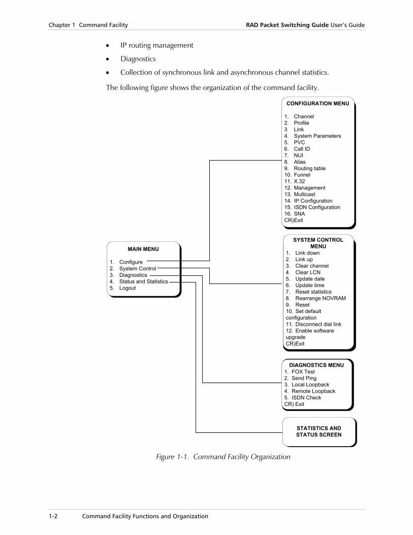
The following figure shows the organization of the command facility.
MAIN MENU
1. Configure2. System Control3. Diagnostics4. Status and Statistics5. Logout
DIAGNOSTICS MENU1. FOX Test2. Send Ping3. Local Loopback4. Remote Loopback5. ISDN CheckCR) Exit
SYSTEM CONTROLMENU
1. Link down2. Link up3. Clear channel4. Clear LCN5. Update date6. Update time7. Reset statistics8. Rearrange NOVRAM9. Reset10. Set defaultconfiguration11. Disconnect dial link12. Enable softwareupgradeCR)Exit
CONFIGURATION MENU
1. Channel2. Profile3 Link4. System Parameters5. PVC6. Call ID7. NUI8. Alias9. Routing table10. Funnel11. X.3212. Management13. Multicast14. IP Configuration15. ISDN Configuration16. SNACR)Exit
STATISTICS ANDSTATUS SCREEN
Figure 1-1. Command Facility Organization
RAD Packet Switching Guide User’s Guide Chapter 1 Command Facility
Starting the Command Facility 1-3
1.2 Starting the Command Facility
Preliminary Preparations Before using a new terminal (not one of the DTEs serving the users connected to the channels), connect it to one of the channels and program its communication parameters to match those of the selected channel.
The default communication parameters are:
• 9600 bps
• 8 data bits
• 1 stop bit
• No parity.
Connecting to the Command Facility By default, access the command facility by setting up a connection to mnemonic address 00.
If the device is not operating
1. Turn your terminal on and set the appropriate communication parameters.
2. Connect the terminal to one of the channels.
3. Turn the device on. After a short interval, the herald message (for example, <DEVICE> CHANNEL NUMBER 1), followed by the PAD prompt (by default, *) appears.
If the device is already operating and the channel you are connected to is engaged in a call
1. Press <CTRL>+<P> to exit the data transfer mode and obtain the PAD prompt *.
2. Disconnect the call by typing CLR and pressing <Enter>.
When the call is cleared, CLR DTE appears on the screen, and the PAD prompt appears in the following line.
To verify that the PAD is free, type: STAT and press <Enter>.
Note
Chapter 1 Command Facility RAD Packet Switching Guide User’s Guide
1-4 Starting the Command Facility
If the device is already operating
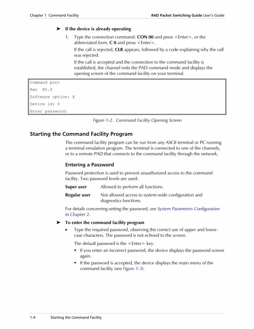
1. Type the connection command: CON 00 and press <Enter>, or the abbreviated form, C 0 and press <Enter>. If the call is rejected, CLR appears, followed by a code explaining why the call was rejected. If the call is accepted and the connection to the command facility is established, the channel exits the PAD command mode and displays the opening screen of the command facility on your terminal.
Command port
Rev R5.0
Software option: X
Device id: 0
Enter password:
Figure 1-2. Command Facility Opening Screen
Starting the Command Facility Program The command facility program can be run from any ASCII terminal or PC running a terminal emulation program. The terminal is connected to one of the channels, or to a remote PAD that connects to the command facility through the network.
Entering a Password
Password protection is used to prevent unauthorized access to the command facility. Two password levels are used:
Super user Allowed to perform all functions.
Regular user Not allowed access to system-wide configuration and diagnostics functions.
For details concerning setting the password, see System Parameters Configuration in Chapter 2.
To enter the command facility program
• Type the required password, observing the correct use of upper and lower-case characters. The password is not echoed to the screen.
The default password is the <Enter> key. If you enter an incorrect password, the device displays the password screen
again. If the password is accepted, the device displays the main menu of the
command facility (see Figure 1-3).

RAD Packet Switching Guide User’s Guide Chapter 1 Command Facility
Starting the Command Facility 1-5
All the channels have equal access to the command facility, and simultaneous access from several channels is possible. If more than one user selects a configuration or diagnostics function, the latecomer sees a message that at least one more user is now connected to the command facility.
Now, you can start a configuration and control session.
To return to the main menu from any screen
• Press <Enter> as many times as necessary.
To end the session
• Select 5 (LOGOUT) on the main menu (see Figure 1-3).
The disconnect confirmation, CLR DTE 0*, appears.
If you changed the communication parameters of the channel connected to the configuration terminal, immediately change the communication parameters of the terminal too. Otherwise, the communication with the terminal will be lost.
MAIN MENU
-----------
1) CONFIGURE
2) SYSTEM CONTROL
3) DIAGNOSTICS
4) STATUS and STATISTICS
5) LOGOUT
Select:
Figure 1-3. Main Menu
Handling the Software Upgrade Notification
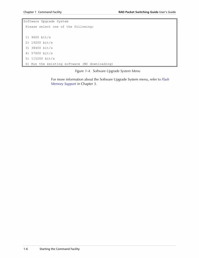
Once the packet switching device has been turned on, there may be cases in which the Software Upgrade System menu is automatically displayed on the terminal screen (see Figure 1-4), while the asynchronous channels (no. 2 and above) become unavailable. This may happen due to erroneous link detection.
If this occurs, it is important that you select ‘Run the existing software (NO downloading)’ to use the existing internal device software. This will return the device to normal functioning and prevent unnecessary RMA or DOA cases, in which the device is returned to the supplier due to malfunction.
Note
Note
Caution
Chapter 1 Command Facility RAD Packet Switching Guide User’s Guide
1-6 Starting the Command Facility
Software Upgrade System
Please select one of the following:
1) 9600 bit/s
2) 19200 bit/s
3) 38400 bit/s
4) 57600 bit/s
5) 115200 bit/s
6) Run the existing software (NO downloading)
Figure 1-4. Software Upgrade System Menu
For more information about the Software Upgrade System menu, refer to Flash Memory Support in Chapter 3.

RAD Packet Switching Guide User’s Guide Chapter 1 Command Facility
Command Facility Operating Procedures 1-7
1.3 Command Facility Operating Procedures
General Operating Procedures The command facility is a simple menu-driven program that guides you through the various configuration steps. To perform a specific function, you have to step down through a sequence of menus.
To select a function:
1. In each screen, type the option number and press <Enter>. At each step, a screen shows all the available selections, and when applicable, also shows the current parameter value.
2. The selection of new parameter values is performed on data entry forms. You can load the new parameter values immediately, or save them for later use.
If a parameter includes the option of choosing “Any combination of the above,” type the sum of the values you want. For example, if you have a choice of values 1, 2, 4, 8... or any combination of the above, setting a value of 6 = (2+4) enables both options 2 and 4).
3. Type S to save the new values. After the new parameter values are saved, the channel continues to operate in accordance with the existing parameter values.
4. To leave the current screen and execute the selections or actions, press <Enter>.
The previous screen appears.
• To exit certain screens, you must type Q (Quit). This option appears as one of the available options on the screen when applicable
• For certain activities, such as profile preparation, on-line context-sensitive help is available. The help information includes concise explanations of parameters and the allowable range of values.
Error Handling The program checks your entries and does not accept invalid entries. For example, if the program expects an entry within a certain range, and you enter a value outside this range, the program displays an error message.
You can rewrite a wrong character command (before pressing <Enter>) by pressing <Delete>. Pressing <Backspace> will generate an error message unless defined differently (Profile Configuration, parameter 16 - Character Delete).
If you make a mistake and lose communication with the command facility, exit the configuration program and start again from the default configuration.
Note
Notes
Chapter 1 Command Facility RAD Packet Switching Guide User’s Guide
1-8 Configuration Menu
1.4 Configuration Menu
Description The Configuration menu provides access to the various configuration functions. For more information on these functions, see Chapter 2, Device Configuration.
The following functions are available from the Configuration menu:
• Channels configuration (set channel type, update or display channels)
• Profile configuration (add, delete, update or display profiles)
• Link configuration (set link type, update or display link parameters)
• System parameters configuration
• Call definition configuration (PVC, call ID or NUI setting)
• Routing table configuration (add, delete, update or display routing table entries)
• Frame Relay Funnel configuration
• X.32 (XID) configuration
• Management facility configuration (SNMP, Event report)
• X.25 multi-cast configuration
• IP configuration (add, delete, update, or display IP routing entries)
• ISDN links configuration
• SNA configuration.
For a picture of the Configuration menu’s hierarchy, see Figure 1-5.
Operation To navigate in the Configuration menu:
1. In the main menu, select 1 (Configuration) and press <Enter>. The Configuration menu appears.
2. Type the number of a function and press <Enter>. The appropriate submenu appears.
3. To return to the main menu, press <Enter> without selecting an option.

RAD Packet Switching Guide User’s Guide Chapter 1 Command Facility
Configuration Menu 1-9
PROFILE CONFIGURATION
1. Add profile2. Delete profile3. Update profile4. Display profiles
CR) Exit
FUNNEL
1. Add Funnel2. Delete Funnel3. Update Funnel4. Display Funnels
CR) Exit
ALIAS
1. Add Alias2. Delete Alias3. Update Alias4. Display Aliases
CR) Exit
MANAGEMENT CONFIGURATION
1. SNMP Agent2. Event Report
CR) Exit
SNA CONFIGURATION
1. SNA Global Configuration parameters2. SNA PU Configuration
CR) Exit
CALL ID CONFIGURATION
1. Add call ID2. Delete call ID3. Update call ID4. Display call IDs
CR) Exit
SYSTEM PARAMETERSCONFIGURATION
CONFIGURATION MENU
1) Channel2) Profile3) Link4) System Parameters5) PVC6) Call ID7) NUI8) Alias9) Routing table10) Funnel11) X.3212) Management13) Multi-Cast14) IP Configuration15) ISDN Configuration16) SNA
CR) Exit
Select:
CHANNEL CONFIGURATION
1. Duplicate channel2. Duplicate channel with
mask3. Update channel4. Display channels5. Set Channel type
CR) Exit
ROUTING TABLE ENTRY CONFIGURATION
1. Add routing table entry2. Delete routing table entry3. Update routing table entry4. Display routing table entries
CR) Exit
NUI DATABASE CONFIGURATION
1. NUI Group ID table2. NUI out table3. Address out table
CR) Exit
XID TABLE CONFIGURATION
1. Add XID table2. Delete XID table3. Update XID table4. Display XID tables
CR) Exit
MULTICAST GROUPCONFIGURATION
1. Add Multicast Group2. Delete Multicast Group3. Update Multicast Group4. Display Multicast Groups
CR) Exit
ISDN CONFIGURATION
1. Global Configuration2. ISDN Routing table3. ISDN Accept List table4. Update ISDN Link parameters5. Display ISDN Link parametersCR) Exit
PVC CONFIGURATION
1. Add PVC2. Delete PVC3. Update PVC4. Display PVCs
CR) Exit
LINK CONFIGURATION
1. Set Link Type2. Display Links protocols3. Update Links parameters4. Display Links parameters
CR) Exit
IP CONFIGURATION
1. IP global parameters2. IP interface3. IP static route
CR) Exit
Figure 1-5. Configuration Menu Hierarchy
Chapter 1 Command Facility RAD Packet Switching Guide User’s Guide
1-10 System Control Menu
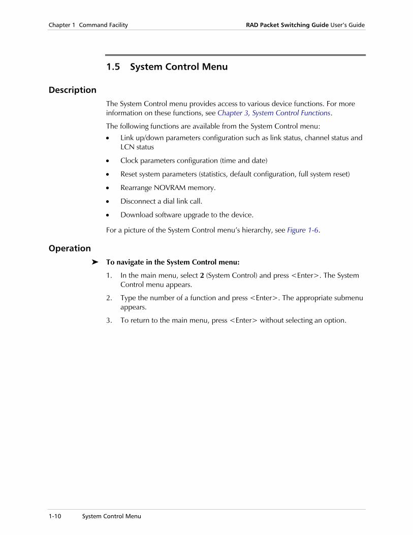
1.5 System Control Menu
Description The System Control menu provides access to various device functions. For more information on these functions, see Chapter 3, System Control Functions.
The following functions are available from the System Control menu:
• Link up/down parameters configuration such as link status, channel status and LCN status
• Clock parameters configuration (time and date)
• Reset system parameters (statistics, default configuration, full system reset)
• Rearrange NOVRAM memory.
• Disconnect a dial link call.
• Download software upgrade to the device.
For a picture of the System Control menu’s hierarchy, see Figure 1-6.
Operation To navigate in the System Control menu:
1. In the main menu, select 2 (System Control) and press <Enter>. The System Control menu appears.
2. Type the number of a function and press <Enter>. The appropriate submenu appears.
3. To return to the main menu, press <Enter> without selecting an option.

RAD Packet Switching Guide User’s Guide Chapter 1 Command Facility
System Control Menu 1-11
SYSTEM CONTROL MENU
1) Link down2) Link up3) Clear channel4) Clear LCN5) Update date6) Update time7) Reset statistics8) Rearrange NOVRAM9) Reset10) Set default configuration11) Disconnect dial link12) Enable software upgradeCR) Exit
LINK UP
LINK DOWN
CLEAR LCN
CLEAR CHANNEL
SET DEFAULT CONFIGURATION
RESET
ENABLE SOFTWARE UPGRADE
DISCONNECT DIAL LINK
REARRANGE NOVRAM
RESET STATISTICS
UPDATE TIME
UPDATE DATE
Figure 1-6. System Control Menu Hierarchy
Chapter 1 Command Facility RAD Packet Switching Guide User’s Guide
1-12 Status and Statistics
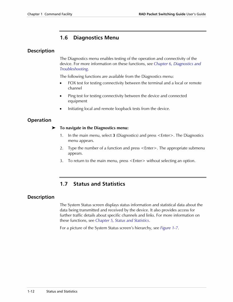
1.6 Diagnostics Menu
Description The Diagnostics menu enables testing of the operation and connectivity of the device. For more information on these functions, see Chapter 6, Diagnostics and Troubleshooting.
The following functions are available from the Diagnostics menu:
• FOX test for testing connectivity between the terminal and a local or remote channel
• Ping test for testing connectivity between the device and connected equipment
• Initiating local and remote loopback tests from the device.
Operation To navigate in the Diagnostics menu:
1. In the main menu, select 3 (Diagnostics) and press <Enter>. The Diagnostics menu appears.
2. Type the number of a function and press <Enter>. The appropriate submenu appears.
3. To return to the main menu, press <Enter> without selecting an option.
1.7 Status and Statistics
Description The System Status screen displays status information and statistical data about the data being transmitted and received by the device. It also provides access for further traffic details about specific channels and links. For more information on these functions, see Chapter 5, Status and Statistics.
For a picture of the System Status screen’s hierarchy, see Figure 1-7.
RAD Packet Switching Guide User’s Guide Chapter 1 Command Facility
Status and Statistics 1-13
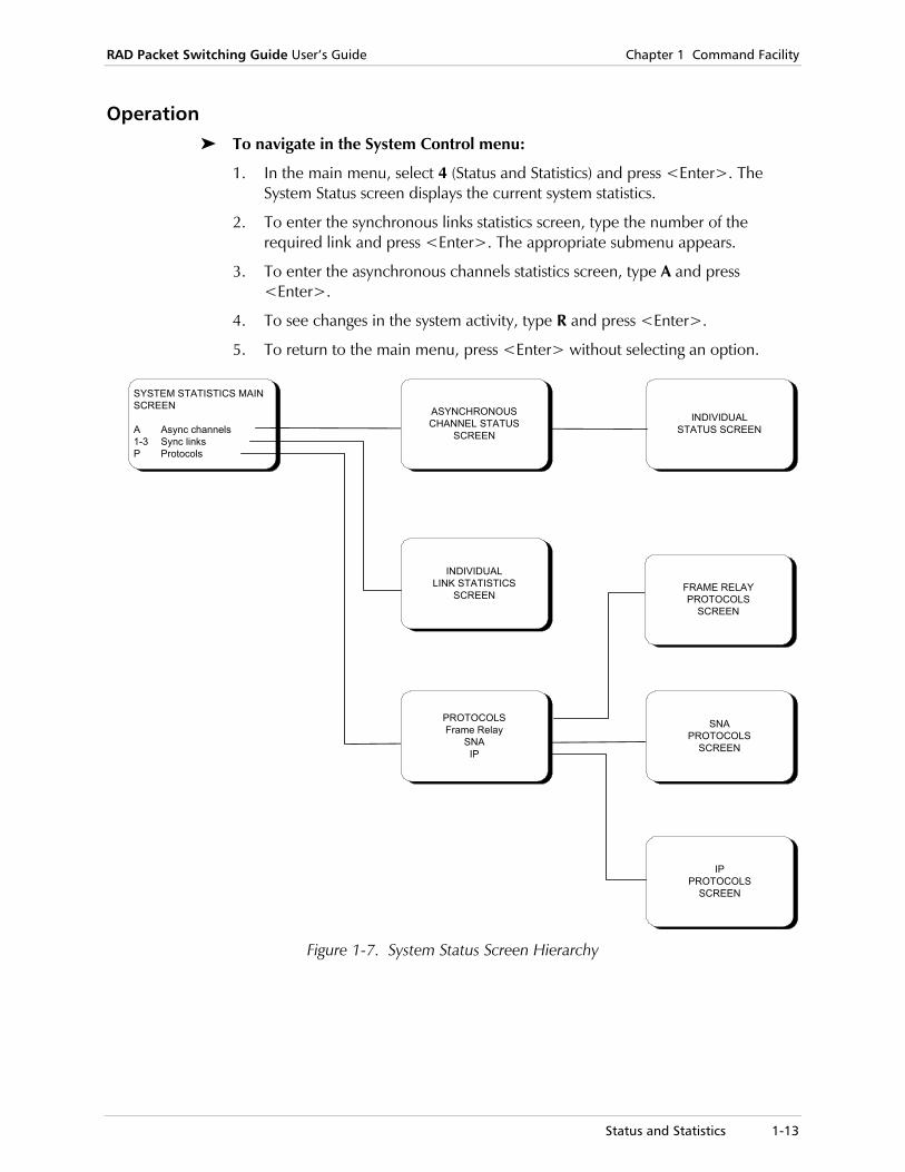
Operation To navigate in the System Control menu:
1. In the main menu, select 4 (Status and Statistics) and press <Enter>. The System Status screen displays the current system statistics.
2. To enter the synchronous links statistics screen, type the number of the required link and press <Enter>. The appropriate submenu appears.
3. To enter the asynchronous channels statistics screen, type A and press <Enter>.
4. To see changes in the system activity, type R and press <Enter>.
5. To return to the main menu, press <Enter> without selecting an option.
SYSTEM STATISTICS MAINSCREEN
A Async channels1-3 Sync linksP Protocols
INDIVIDUALSTATUS SCREEN
INDIVIDUALLINK STATISTICS
SCREEN
ASYNCHRONOUSCHANNEL STATUS
SCREEN
PROTOCOLSFrame Relay
SNAIP
IPPROTOCOLS
SCREEN
FRAME RELAYPROTOCOLS
SCREEN
SNAPROTOCOLS
SCREEN
Figure 1-7. System Status Screen Hierarchy

Chapter 1 Command Facility RAD Packet Switching Guide User’s Guide
1-14 Status and Statistics

Channel Configuration 2-1
Chapter 2 Device Configuration This chapter:
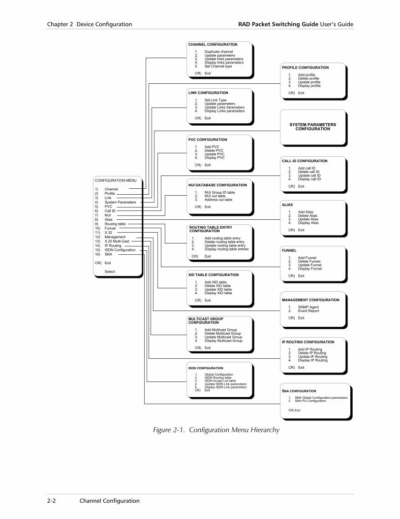
• Explains the device configuration functions available through the Configuration menu (see Figure 2-1).
• Includes definitions of the PAD parameters and device configuration parameters.
The information in this chapter is intended for users who are already knowledgeable of the basic concepts of X.25/FR packet switched data networks, PAD commands and PAD/FRAD parameters.
• The term “device” refers to the RAD series of Packet Switching devices (APS series, SPS series, APD series and FPS series devices).
• If a parameter includes the option of choosing “Any combination of the above,” type the sum of the values you want. For example, if you have a choice of values 1, 2, 4, 8... or any combination of the above, setting a value of 6 = (2+4) enables both options 2 and 4).
Note
Chapter 2 Device Configuration RAD Packet Switching Guide User’s Guide
2-2 Channel Configuration
PROFILE CONFIGURATION
1. Add profile2. Delete profile3. Update profile4. Display profile
CR) Exit
FUNNEL
1. Add Funnel2. Delete Funnel3. Update Funnel4. Display Funnel
CR) Exit
ALIAS
1. Add Alias2. Delete Alias3. Update Alias4. Display Alias
CR) Exit
MANAGEMENT CONFIGURATION
1. SNMP Agent2. Event Report
CR) Exit
IP ROUTING CONFIGURATION
1. Add IP Routing2. Delete IP Routing3. Update IP Routing4. Display IP Routing
CR) Exit
SNA CONFIGURATION
1. SNA Global Configuration parameters2. SNA PU Configuration
CR) Exit
CALL ID CONFIGURATION
1. Add call ID2. Delete call ID3. Update call ID4. Display call ID
CR) Exit
SYSTEM PARAMETERSCONFIGURATION
CONFIGURATION MENU
1) Channel2) Profile3) Link4) System Parameters5) PVC6) Call ID7) NUI8) Alias9) Routing table10) Funnel11) X.3212) Management13) X.25 Multi-Cast14) IP Routing15) ISDN Configuration16) SNA
CR) Exit
Select:
CHANNEL CONFIGURATION
1. Duplicate channel2. Update parameters3. Update links parameters4. Display links parameters5. Set Channel type
CR) Exit
ROUTING TABLE ENTRY CONFIGURATION
1. Add routing table entry2. Delete routing table entry3. Update routing table entry4. Display routing table entries
CR) Exit
NUI DATABASE CONFIGURATION
1. NUI Group ID table2. NUI out table3. Address out table
CR) Exit
XID TABLE CONFIGURATION
1. Add XID table2. Delete XID table3. Update XID table4. Display XID table
CR) Exit
MULTICAST GROUPCONFIGURATION
1. Add Multicast Group2. Delete Multicast Group3. Update Multicast Group4. Display Multicast Group
CR) Exit
ISDN CONFIGURATION
1. Global Configuration2. ISDN Routing table3. ISDN Accept List table4. Update ISDN Link parameters5. Display ISDN Link parametersCR) Exit
PVC CONFIGURATION
1. Add PVC2. Delete PVC3. Update PVC4. Display PVC
CR) Exit
LINK CONFIGURATION
1. Set Link Type2. Update parameters3. Update Links ôarameters4. Display Links parameters
CR) Exit
Figure 2-1. Configuration Menu Hierarchy

RAD Packet Switching Guide User’s Guide Chapter 2 Device Configuration
Channel Configuration 2-3
2.1 Channel Configuration
From the Channel Configuration menu, you can:
• Set the protocol type for a specific channel
• Update the configuration parameters of a selected channel
• Duplicate the configuration parameters of a selected channel to one or more other channels. The duplicated parameters can then be changed by the user
• Apply a mask when duplicating the configuration parameters
• Display the current configuration parameters of all the device channels.
This section also contains descriptions of parameters for the following channel types:
• X.28
• SLIP
• PPP.
To use the Channel Configuration menu:
1. In the Configuration menu, select 1 (Channel) and press <Enter>. The Channel Configuration menu appears.
Channel configuration
-----------------------
1) Duplicate channel
2) Duplicate channel with mask
3) Update channel
4) Display channels
5) Set Channel Type
CR) Exit
Select:
Figure 2-2. Channel Configuration Menu
2. Type the number of a function and press <Enter>. The appropriate menu appears.
3. To return to the Configuration menu, press <Enter> without selecting an option.
Chapter 2 Device Configuration RAD Packet Switching Guide User’s Guide
2-4 Channel Configuration
Set Channel Type Use the Set Channel Type function to select and set the channel type.
The possible channel protocols are:
• X.28
• SLIP
• PPP.
To set the channel type:
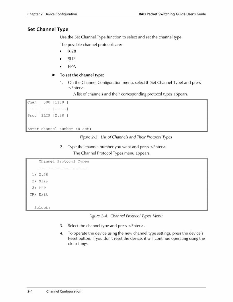
1. On the Channel Configuration menu, select 5 (Set Channel Type) and press <Enter>.
A list of channels and their corresponding protocol types appears.
Chan | 300 |1100 |
-----|-----|-----|
Prot |SLIP |X.28 |
Enter channel number to set:
Figure 2-3. List of Channels and Their Protocol Types
2. Type the channel number you want and press <Enter>. The Channel Protocol Types menu appears.
Channel Protocol Types
-----------------------
1) X.28
2) Slip
3) PPP
CR) Exit
Select:
Figure 2-4. Channel Protocol Types Menu
3. Select the channel type and press <Enter>.
4. To operate the device using the new channel type settings, press the device’s Reset button. If you don’t reset the device, it will continue operating using the old settings.

RAD Packet Switching Guide User’s Guide Chapter 2 Device Configuration
Channel Configuration 2-5
Update Channel Use the Update Channel option to update the three types of channels (X.28, PPP and SLIP), in accordance with the Channel Type you selected (see Set Channel Type on page 2-4).
1. In the Channel Configuration menu, select 3 (Update channel) and press <Enter>.
A list of channels and their corresponding protocol types appears.
2. Type the number of the channel you want and press <Enter>. The system automatically displays the configuration screen relevant to the selected channel.
3. To configure a specific parameter, type its number and press <Enter>. The device prompts you for the new parameter value.
4. Type a new parameter value and press <Enter>. The new value appears in the value column.
5. Type S and press <Enter> to save the new configuration.
To cancel the changes you made, exit without saving the new values.
6. To exit the Channel n Configuration screen and return to the Channel Configuration menu, press <Enter> without making any parameter selection.
Duplicate Channel Use the Duplicate Channel function to copy the configuration information of a selected channel to one or more channels.
To duplicate a channel configuration:
1. In the Channel Configuration menu, select 1 (Duplicate channel) and press <Enter>.
A list of existing channels prompts you for the number of the source channel.
2. Type a channel number and press <Enter>. The device prompts you for the range of channels to which you want to copy the source channel configuration.
3. Type the numbers of the first and last channels, separated by a colon (:), and press <Enter>.
If you want to copy to a single channel, type its number twice (for example, 100:100).
If the source and target channel numbers are valid, the device confirms the execution of the command, and prompts you to press <Enter> to continue.
Note
Chapter 2 Device Configuration RAD Packet Switching Guide User’s Guide
2-6 Channel Configuration
Duplicate Channel with Mask Use the Duplicate Channel with Mask function to copy the values of selected configuration parameters from a source channel to one or more target channels. The values of the other parameters of the target channels are not affected by this operation.
To duplicate a channel configuration with a mask:
1. On the Channel Configuration menu, select 2 (Duplicate channel with mask) and press <Enter>.
A list of existing channels prompts you for the number of the source channel.
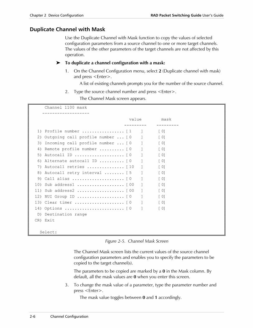
2. Type the source channel number and press <Enter>. The Channel Mask screen appears.
Channel 1100 mask ------------------- value mask --------- --------- 1) Profile number ................. [1 ] [0] 2) Outgoing call profile number ... [0 ] [0] 3) Incoming call profile number ... [0 ] [0] 4) Remote profile number .......... [0 ] [0] 5) Autocall ID .................... [0 ] [0] 6) Alternate autocall ID .......... [0 ] [0] 7) Autocall retries ............... [10 ] [0] 8) Autocall retry interval ........ [5 ] [0] 9) Call alias ..................... [0 ] [0] 10) Sub address1 ................... [00 ] [0] 11) Sub address2 ................... [00 ] [0] 12) NUI Group ID ................... [0 ] [0] 13) Clear timer .................... [0 ] [0] 14) Options ........................ [0 ] [0] D) Destination range CR) Exit Select:
Figure 2-5. Channel Mask Screen
The Channel Mask screen lists the current values of the source channel configuration parameters and enables you to specify the parameters to be copied to the target channel(s).
The parameters to be copied are marked by a 0 in the Mask column. By default, all the mask values are 0 when you enter this screen.
3. To change the mask value of a parameter, type the parameter number and press <Enter>.
The mask value toggles between 0 and 1 accordingly.
RAD Packet Switching Guide User’s Guide Chapter 2 Device Configuration
Channel Configuration 2-7
4. To select the range of target channels, type D (Destination Range) and press <Enter>.
The device prompts you for the range of target channels.
5. Type the numbers of the first and last channels, separated by a colon (:), and press <Enter>.
If you want to copy to a single channel, type its number twice (for example, 100:100).
If the source and target channel numbers are valid, the device confirms the execution of the command, and prompts you to press <Enter> to continue.
Display Channels Use the Display Channels function to display the configuration parameters of channels running a specific protocol.
To display the channel configurations:
1. On the Channel Configuration submenu, select 4 (Display Channels) and press <Enter>.
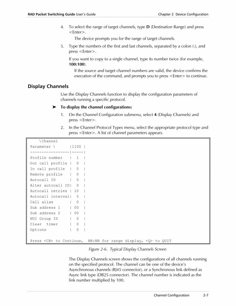
2. In the Channel Protocol Types menu, select the appropriate protocol type and press <Enter>. A list of channel parameters appears.
\Channel Parameter \ |1100 | -----------------|-----| Profile number | 1 | Out call profile | 0 | In call profile | 0 | Remote profile | 0 | Autocall ID | 0 | Alter autocall ID| 0 | Autocall retries | 10 | Autocall interval| 5 | Call alias | 0 | Sub address 1 | 00 | Sub address 2 | 00 | NUI Group ID | 0 | Clear timer | 0 | Options | 0 | Press <CR> to Continue, NN:NN for range display, <Q> to QUIT
Figure 2-6. Typical Display Channels Screen
The Display Channels screen shows the configurations of all channels running on the specified protocol. The channel can be one of the device’s Asynchronous channels (RJ45 connector), or a Synchronous link defined as Async link type (DB25 connector). The channel number is indicated as the link number multiplied by 100.

Chapter 2 Device Configuration RAD Packet Switching Guide User’s Guide
2-8 Channel Configuration
3. To view a specific range of channels, type the numbers of the first and last channel separated by a colon (:) and press <Enter>. For example, to display channels 2 through 5, type 2:5.
4. To quit the list, type Q and press <Enter>.
X.28 Channel Parameters X.28 is the default protocol type for the device’s channels. If the channel is set to X.28 protocol, the Channel n Configuration screen contains the configuration data of the selected channel. The channel is identified in the screen title.
Channel 1100 configuration
------------------------------
1) Profile number ................. [1 ]
2) Outgoing call profile number ... [0 ]
3) Incoming call profile number ... [0 ]
4) Remote profile number .......... [0 ]
5) Autocall ID .................... [0 ]
6) Alternate autocall ID .......... [0 ]
7) Autocall retries ............... [10 ]
8) Autocall retry interval ........ [5 ]
9) Call alias ..................... [0 ]
10) Sub address1 ................... [00 ]
11) Sub address2 ................... [00 ]
12) NUI Group ID ................... [0 ]
13) Clear timer .................... [0 ]
14) Options ........................ [0 ]
S) Save
CR) Exit
Select:
Figure 2-7. X.28 Channel Configuration Screen
RAD Packet Switching Guide User’s Guide Chapter 2 Device Configuration
Channel Configuration 2-9
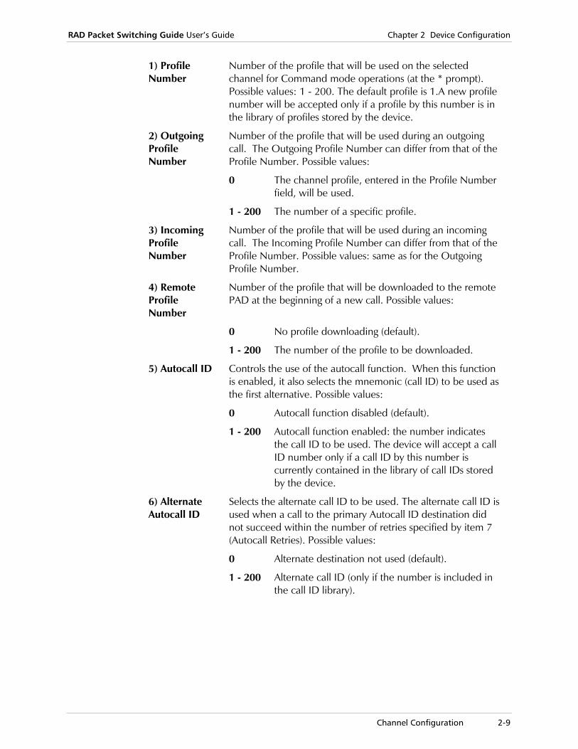
1) Profile Number
Number of the profile that will be used on the selected channel for Command mode operations (at the * prompt). Possible values: 1 - 200. The default profile is 1.A new profile number will be accepted only if a profile by this number is in the library of profiles stored by the device.
2) Outgoing Profile Number
Number of the profile that will be used during an outgoing call. The Outgoing Profile Number can differ from that of the Profile Number. Possible values:
0 The channel profile, entered in the Profile Number field, will be used.
1 - 200 The number of a specific profile.
3) Incoming Profile Number
Number of the profile that will be used during an incoming call. The Incoming Profile Number can differ from that of the Profile Number. Possible values: same as for the Outgoing Profile Number.
4) Remote Profile Number
Number of the profile that will be downloaded to the remote PAD at the beginning of a new call. Possible values:
0 No profile downloading (default).
1 - 200 The number of the profile to be downloaded.
5) Autocall ID Controls the use of the autocall function. When this function is enabled, it also selects the mnemonic (call ID) to be used as the first alternative. Possible values:
0 Autocall function disabled (default).
1 - 200 Autocall function enabled: the number indicates the call ID to be used. The device will accept a call ID number only if a call ID by this number is currently contained in the library of call IDs stored by the device.
6) Alternate Autocall ID
Selects the alternate call ID to be used. The alternate call ID is used when a call to the primary Autocall ID destination did not succeed within the number of retries specified by item 7 (Autocall Retries). Possible values:
0 Alternate destination not used (default).
1 - 200 Alternate call ID (only if the number is included in the call ID library).

Chapter 2 Device Configuration RAD Packet Switching Guide User’s Guide
2-10 Channel Configuration
7) Autocall Retries
Number of times that the device trys to call the first Autocall ID (parameter 5). If the call does not succeed, the device calls the Alternate Autocall ID (parameter 6) the specified number of retries. If the call still does not succeed, the device channel can either stop Autocall retrying or restart the Autocall Retry process over again. Possible values:
0 No options.
1 - 127 Number of autocall retries.
128 The device repeats the Autocall process until call setup or user interruption.
XXX Any combination of the above values.
The default value is 5.
8) Autocall Retry Interval
If the device is set for automatic call retries, specify the interval (in seconds) between consecutive retries. Possible values: 0 - 255.The default value is 5.
9) Call Alias Number of the alias that the device channel PAD sends after the call is set up. Possible values:
0 No alias sending (default).
1 - 200 The device sends the specified alias when it initiates a call.
An alias (number) entry will be accepted only if it currently exists in the Devices Alias library. You can prepare aliases through the Alias screen (see Alias Configuration on page 2-124).
10) Subaddress 1 11) Subaddress 2
The device ASYNC channel can be assigned two sub-addresses. Channels with the same sub-address form a group. These fields are used to assign the desired sub-addresses. Possible values: 0 - 255.By default, sub-address 1 is equal to the physical channel number, and the other sub-address is 0.
12) NUI Group ID
The device PAD channel’s Network User Identifier (NUI). If used, the NUI is set up through the NUI Group ID table (see NUI Configuration on page 2-111). Possible values:
0 Automatic sending of a NUI is disabled (default).
1 – 200 The device sends the NUI information included in this NUI Group ID in accordance with the ITU facilities block of call set up requests. The NUI Group ID entry is accepted only if a Group ID by this number exists in the device NUI library.
Note
RAD Packet Switching Guide User’s Guide Chapter 2 Device Configuration
Channel Configuration 2-11
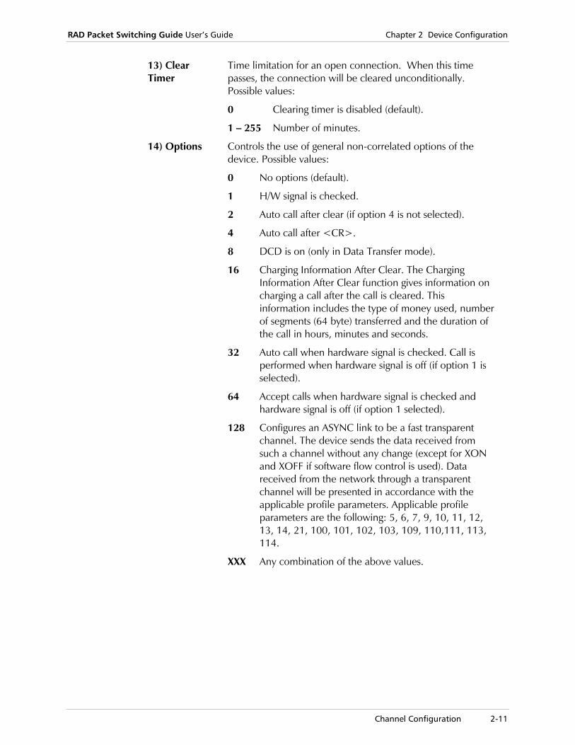
13) Clear Timer
Time limitation for an open connection. When this time passes, the connection will be cleared unconditionally. Possible values:
0 Clearing timer is disabled (default).
1 – 255 Number of minutes.
14) Options Controls the use of general non-correlated options of the device. Possible values:
0 No options (default).
1 H/W signal is checked.
2 Auto call after clear (if option 4 is not selected).
4 Auto call after <CR>.
8 DCD is on (only in Data Transfer mode).
16 Charging Information After Clear. The Charging Information After Clear function gives information on charging a call after the call is cleared. This information includes the type of money used, number of segments (64 byte) transferred and the duration of the call in hours, minutes and seconds.
32 Auto call when hardware signal is checked. Call is performed when hardware signal is off (if option 1 is selected).
64 Accept calls when hardware signal is checked and hardware signal is off (if option 1 selected).
128 Configures an ASYNC link to be a fast transparent channel. The device sends the data received from such a channel without any change (except for XON and XOFF if software flow control is used). Data received from the network through a transparent channel will be presented in accordance with the applicable profile parameters. Applicable profile parameters are the following: 5, 6, 7, 9, 10, 11, 12, 13, 14, 21, 100, 101, 102, 103, 109, 110,111, 113, 114.
XXX Any combination of the above values.

Chapter 2 Device Configuration RAD Packet Switching Guide User’s Guide
2-12 Channel Configuration
SLIP Channel Parameters SLIP (Serial Link Internet Protocol) enables IP communication over an ASYNC channel or link. If the selected channel is set to SLIP protocol, the SLIP n Configuration screen contains the configuration data of the selected channel. The channel is identified in the screen title.
SLIP 300 Configuration
----------------------------
1) Speed ........................ [ 14]
2) Flow control options ......... [ 0]
3) Stop bits .................... [ 0]
4) Bits / char .................. [ 3]
5) Parity ....................... [ 0]
S) Save.
CR) Exit.
Select:
Figure 2-8. SLIP Link Configuration Screen
1) Speed The rate of data transmission over this channel to and from the DTE. Possible values:
0 110 bps
2 300 bps
3 1200 bps
4 600 bps
5 75 bps
6 150 bps
12 2400 bps
13 4800 bps
14 9600 bps (default)
15 19.2 kbps
19 38.4 kbps
20 57.6 kbps
21 115.2 kbps
RAD Packet Switching Guide User’s Guide Chapter 2 Device Configuration
Channel Configuration 2-13
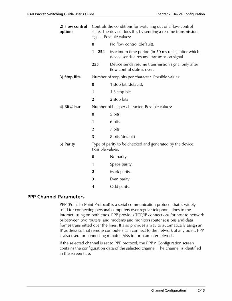
2) Flow control options
Controls the conditions for switching out of a flow-control state. The device does this by sending a resume transmission signal. Possible values:
0 No flow control (default).
1 - 254 Maximum time period (in 50 ms units), after which device sends a resume transmission signal.
255 Device sends resume transmission signal only after flow control state is over.
3) Stop Bits Number of stop bits per character. Possible values:
0 1 stop bit (default).
1 1.5 stop bits
2 2 stop bits
4) Bits/char Number of bits per character. Possible values:
0 5 bits
1 6 bits
2 7 bits
3 8 bits (default)
5) Parity Type of parity to be checked and generated by the device. Possible values:
0 No parity.
1 Space parity.
2 Mark parity.
3 Even parity.
4 Odd parity.
PPP Channel Parameters PPP (Point-to-Point Protocol) is a serial communication protocol that is widely used for connecting personal computers over regular telephone lines to the Internet, using on both ends. PPP provides TCP/IP connections for host to network or between two routers, and modems and monitors router sessions and data frames transmitted over the lines. It also provides a way to automatically assign an IP address so that remote computers can connect to the network at any point. PPP is also used for connecting remote LANs to form an internetwork.
If the selected channel is set to PPP protocol, the PPP n Configuration screen contains the configuration data of the selected channel. The channel is identified in the screen title.

Chapter 2 Device Configuration RAD Packet Switching Guide User’s Guide
2-14 Channel Configuration
PPP 700 Configuration ---------------------------- 1) Speed ........... [ 14 ] 6) Signal Check ........... [ 0 ] 2) Flow control .... [ 0 ] 7) Link Alive Time ........ [ 0 ] 3) Stop bits ....... [ 0 ] 8) MRU ................. [ 1500 ] 4) Bits / char ..... [ 3 ] 9) ACCM ................ [ ] 5) Parity .......... [ 0 ] Port authentication ------------------- 10) Port Authentication type ..... [ 0 ] 11) Port User name ............... [ ] 12) Port Password ................ [ ] Modem Commands -------------- 13) Modem Init String ............ [ ] 14) Modem Dial String ............ [ ] S) Save. CR) Exit. Select:
Figure 2-9. PPP Channel Configuration Screen
If PAP authentication is being used, another unit connected to this line may detect the password.
1) Speed The rate of data transmission over this channel to and from the DTE. Possible values:
0 110 bps 2 300 bps 3 1200 bps 4 600 bps 5 75 bps 6 150 bps 12 2400 bps 13 4800 bps 14 9600 bps (default) 15 19.2 kbps 19 38.4 kbps 20 57.6 kbps 21 115.2 kbps
Note

RAD Packet Switching Guide User’s Guide Chapter 2 Device Configuration
Channel Configuration 2-15
2) Flow control options
Controls the conditions for switching out of a flow-control state. The device does this by sending a resume transmission signal. Possible values:
0 No flow control (default).
1 – 254 Maximum time period (in 50 ms units), after which device sends a resume transmission signal.
255 Device sends resume transmission signal only after flow control state is over.
3) Stop Bits Number of stop bits per character. Possible values:
0 1 stop bit (default).
1 1.5 stop bits
2 2 stop bits
4) Bits/char Number of bits per character. Possible values:
0 5 bits
1 6 bits
2 7 bits
3 8 bits (default)
5) Parity Type of parity to be checked and generated by the device. Possible values:
0 No parity.
1 Space parity.
2 Mark parity.
3 Even parity.
4 Odd parity.
6) Signal Check
Options for initiating the negotiation between the device and remote equipment connected to this channel. Possible values:
0 Negotiation starts after the device is reset.
1 Negotiation starts upon signal assertion. For DCE, the DTR signal is checked. For DTE, the DCD signal is checked.
2 Data Triggered. Asserts DTR/DSR. Negotiation starts after the device receives data at this channel.
3 Options 1 + 2 (default).
7) Link Alive Time
Interval between Keep-alive packets over the channel. Possible values: 5 - 10 seconds. Default value is 5.
8) MRU Maximum Receive Unit - maximum packet size that the device can receive. During negotiation, device sends this information to the remote equipment connected to this channel. Possible values: 1500 - 4096 bytes. Default value is 1500.

Chapter 2 Device Configuration RAD Packet Switching Guide User’s Guide
2-16 Channel Configuration
9) ACCM Async Control Character Map - Mask for the first 32 characters in the ASCII table. This value informs the connected equipment which characters cannot be read as data. Possible values: 8 hexadecimal characters (32 bits). Each bit can be one of the following:
0 Character remains as is.
1 Character that should be escaped by the peer.
For example, to use XON and XOFF as an escape sequence, type 000A0000.
10) Port Authentication Type
Type of authentication, if applicable, used on this port (see PAP/CHAP Authentication Configuration on page 2-97). Possible values:
0 No authentication. Channel functions only as the user side (default).
1 PAP or CHAP authentication as the host.
2 CHAP authentication as the host.
11) Port User Name
The port’s ID. Identifies the device to the remote equipment during authentication phase of the negotiation. Possible values: Up to 20 alphanumeric characters. To remove this value, press <SPACE>.
12) Port Password
Password for accessing the port. If required, this password is used during the authentication phase of the negotiation. Possible values: Up to 20 alphanumeric characters. To remove this value, press <SPACE>.
13 and 14 – Modem Init/Dial String
The new parameters in the PPP channel configuration allow working with a variety of modems. For example, GPRS modems should receive a special initial string before sending the dial string. The PS device will start a PPP negotiation just after receiving the connection message.
13) Modem Init String – Modem initialization string, composed of alphanumeric characters, 29 characters max.
If you want to erase the field, press <SPACE>.
14) Modem Dial String – Modem dial string, composed of alphanumeric characters, 29 characters max.
If you want to erase the field, press <SPACE>.
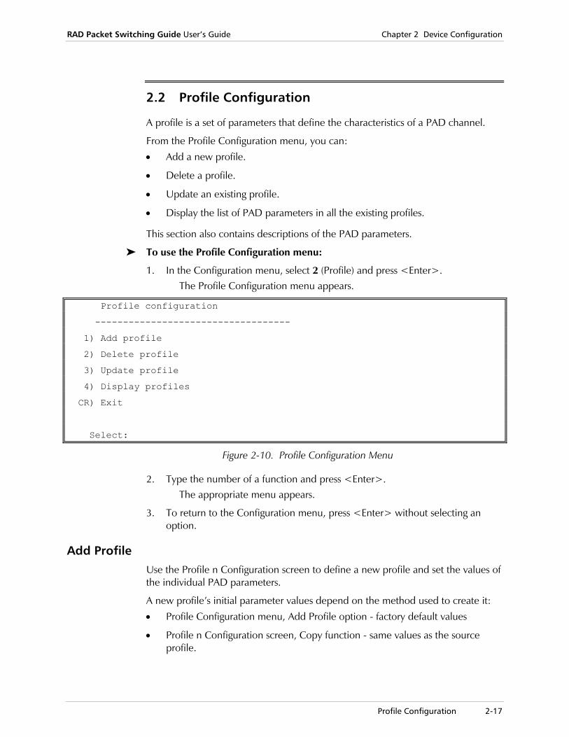
RAD Packet Switching Guide User’s Guide Chapter 2 Device Configuration
Profile Configuration 2-17
2.2 Profile Configuration
A profile is a set of parameters that define the characteristics of a PAD channel.
From the Profile Configuration menu, you can:
• Add a new profile.
• Delete a profile.
• Update an existing profile.
• Display the list of PAD parameters in all the existing profiles.
This section also contains descriptions of the PAD parameters.
To use the Profile Configuration menu:
1. In the Configuration menu, select 2 (Profile) and press <Enter>. The Profile Configuration menu appears.
Profile configuration
-----------------------------------
1) Add profile
2) Delete profile
3) Update profile
4) Display profiles
CR) Exit
Select:
Figure 2-10. Profile Configuration Menu
2. Type the number of a function and press <Enter>. The appropriate menu appears.
3. To return to the Configuration menu, press <Enter> without selecting an option.
Add Profile Use the Profile n Configuration screen to define a new profile and set the values of the individual PAD parameters.
A new profile’s initial parameter values depend on the method used to create it:
• Profile Configuration menu, Add Profile option - factory default values
• Profile n Configuration screen, Copy function - same values as the source profile.

Chapter 2 Device Configuration RAD Packet Switching Guide User’s Guide
2-18 Profile Configuration
To add a profile:
1. In the Configuration menu, select 2 (Profile) and press <Enter>. The Profile Configuration menu appears.
2. Select 1 (Add Profile) and press <Enter>.
3. A list of existing profile numbers appears. Type a new profile number (1 - 200) and press <Enter>.
The Profile n Configuration screen appears, displaying the default parameters. The number of the profile appears in the screen title (n). For descriptions of the profile parameters, see PAD Parameters on page 2-20.
4. To configure a specific parameter, type its number and press <Enter>. The device prompts you for the new parameter value.
5. Type a new parameter value and press <Enter>. The new value appears in the value column.
6. Type S and press <Enter> to save the new configuration.
To cancel the changes you made, exit without saving the new values.
7. To exit the Profile n Configuration screen and return to the Profile Configuration menu, press <Enter> without making any parameter selection.
See Figure 2-11 for the default Profile n Configuration screen.
To add a profile by copying an existing one:
1. In the Configuration menu, select 2 (Profile) and press <Enter>. The Profile Configuration menu appears.
2. Select 3 (Update Profile) and press <Enter>.
3. A list of existing profile numbers appears. Type the number (1 - 200) of the profile that you want to copy and press <Enter>.
The Profile n Configuration screen appears, displaying the selected profile’s parameters.
4. Type C (Copy) and press <Enter>.
5. A list of existing profile numbers appears again. Type a new profile number (1 - 200) and press <Enter>.
The Profile n Configuration screen appears again, displaying the new profile’s parameters.
6. To configure a specific parameter, type its number and press <Enter>. The device prompts you for the new parameter value.
7. Type a new parameter value and press <Enter>. The new value appears in the value column.
Note
RAD Packet Switching Guide User’s Guide Chapter 2 Device Configuration
Profile Configuration 2-19
8. Type S and press <Enter> to save the new configuration.
To cancel the changes you made, exit without saving the new values.
9. To exit the Profile n Configuration screen and return to the Profile Configuration menu, press <Enter> without making any parameter selection.
Update Profile Use the Update Profile function to change parameter values in an existing profile.
1. In the Configuration menu, select 2 (Profile) and press <Enter>.
2. In the Profile Configuration menu, select 3 (Update profile) and press <Enter>.
3. A list of existing profile numbers appears. Type the number (1 - 200) of the profile that you want to update and press <Enter>.
The Profile n Configuration screen appears, displaying the default parameters. The number of the profile appears in the screen title (n).
4. Change parameter values as required. For a description of parameter values, see PAD Parameters on page 2-20.
5. Type S and press <Enter> to save the new configuration.
To cancel the changes you made, exit without saving the new values.
6. To exit the Profile n Configuration screen and return to the Profile Configuration menu, press <Enter> without making any parameter selection.
Delete Profile Use the Delete Profile function to delete an existing profile from the device database. After deletion, the profile is no longer available to any device channel. Before deletion, make sure other channels no longer use the profile.
If you try to delete a profile used by another channel, the device will display an error message.
To delete a profile:
1. In the Configuration menu, select 2 (Profile) and press <Enter>.
2. In the Profile Configuration menu, select 2 (Delete profile) and press <Enter>.
3. A list of existing profile numbers appears. Type the number (1 - 200) of the profile that you want to delete and press <Enter>.
After the deletion, the device returns to the Profile Configuration menu.
Note
Note

Chapter 2 Device Configuration RAD Packet Switching Guide User’s Guide
2-20 Profile Configuration
Display Profiles Use the Display Profiles function to display the parameters of all or some of the profiles stored in the device database.
To display the profile list:
1. In the Configuration menu, select 2 (Profile) and press <Enter>.
2. In the Profile Configuration menu, select 4 (Display Profiles) and press <Enter>.
The device displays the first group of parameters of up to ten profiles.
3. If the device stores more than 10 profiles, press <Enter> to continue to another screen.
4. On the last screen, press <Enter> to return to the Profile Configuration menu.
PAD Parameters The Profile n Configuration screen contains the PAD parameters. The number of the profile appears in the screen title (n).
The menu selection numbers used are identical with the parameter reference numbers as defined by ITU Rec. X.3, or to the numbers of the RAD extended set of parameters.
The parameters included in the standard ITU Rec. X.3 set for PADs perform the following functions:
• Control PAD operation (parameters 1, 6, 15, 16, 17, 18, 19)
• Control the echo provided to the DTE (parameters 2, 20)
• Control data forwarding (parameters 3, 4)
• Data flow control (parameters 5, 12)
• Control the formatting of user data by the PAD (parameters 9, 10, 13, 14, 21).
The proprietary RAD parameters from 100-113 perform the following functions:
• Control the word format of data accepted from, and sent to, the user DTE (parameters 100, 101, 102)
• Enhance user data flow control (parameters 103, 104, 105, 106, 110)
• Enhance the formatting of user data by the PAD (parameter 109)
• Enhance echo control functions (parameters 107, 108).
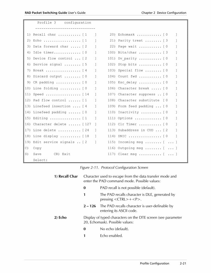
RAD Packet Switching Guide User’s Guide Chapter 2 Device Configuration
Profile Configuration 2-21
Profile 3 configuration
-----------------------------
1) Recall char ........... [1 ] 20) Echomask ............ [0 ]
2) Echo .................. [1 ] 21) Parity treat ........ [3 ]
3) Data forward char ..... [2 ] 22) Page wait ........... [0 ]
4) Idle timer............. [0 ] 100) Bits/char ........... [3 ]
5) Device flow control ... [2 ] 101) Dv_parity ........... [0 ]
6) Service signal ........ [5 ] 102) Stop bits ........... [0 ]
7) Break ................. [4 ] 103) Special flow ........ [0 ]
8) Discard output ........ [0 ] 104) Count fwd ........... [0 ]
9) CR padding ............ [0 ] 105) Esc_delay ........... [0 ]
10) Line folding .......... [0 ] 106) Character break ..... [0 ]
11) Speed ................. [14 ] 107) Character suppress .. [0 ]
12) Pad flow control ...... [1 ] 108) Character substitute [0 ]
13) Linefeed insertion .... [4 ] 109) Form feed padding ... [0 ]
14) Linefeed padding ...... [0 ] 110) Inactivity .......... [0 ]
15) Editing ............... [1 ] 111) Options ............. [0 ]
16) Character delete ...... [127 ] 112) Clr Timer ........... [0 ]
17) Line delete ........... [24 ] 113) Subaddress in CUD ... [2 ]
18) Line display .......... [18 ] 114) DNIC ................ [0 ]
19) Edit service signals .. [2 ] 115) Incoming msg ........ [ ... ]
C) Copy 116) Outgoing msg ........ [ ... ]
S) Save CR) Exit 117) Clear msg ........... [ ... ]
Select:
Figure 2-11. Protocol Configuration Screen
1) Recall Char Character used to escape from the data transfer mode and enter the PAD command mode. Possible values:
0 PAD recall is not possible (default).
1 The PAD recalls character is DLE, generated by pressing <CTRL>+<P>.
2 – 126 The PAD recalls character is user-definable by entering its ASCII code.
2) Echo Display of typed characters on the DTE screen (see parameter 20, Echomask). Possible values:
0 No echo (default).
1 Echo enabled.

Chapter 2 Device Configuration RAD Packet Switching Guide User’s Guide
2-22 Profile Configuration
3) Data forward char
When the PAD receives one of these characters it immediately finishes assembling the current packet with the data accumulated until that point. The PAD then forwards the packet. Possible values:
0 No data forwarding character.
1 Alphanumeric characters (A - Z, a - z, 1 - 9).
2 CR character (default).
4 ESC, BEL, ENQ, ACK characters.
8 DEL, CAN, DC2 characters.
16 EOT, ETX characters.
32 HT, LF, VT, FF characters.
64 All other characters in columns 0 and 1 of IA5 that are not included above.
XX Any combination of the above values.
Packets are automatically forwarded when the edit buffer is full, even if the device did not receive the data forwarding character
4) Idle Timer If this time interval passes between two consecutive characters, the PAD immediately finishes assembling the current data packet, and forwards it. This occurs even if the other required conditions for packet forwarding have not been met. Possible values:
0 No forwarding after idle condition (default).
1 – 255 Maximum interval between two consecutive characters (in multiples of 50 ms). For example, a value of 60 sets an interval of 3 seconds.
5) Device Flow Control
Determines if the PAD uses software flow control for the DTE. The PAD sends the X-OFF (DC3) character to stop transmission, and the X-ON (DC1) character to signal the DTE of transmission (see also parameter 12). Possible values:
0 No flow control.
1 PAD uses flow control during data transfer mode.
2 PAD uses flow control both in the data transfer mode and in the command mode (default).
Note

RAD Packet Switching Guide User’s Guide Chapter 2 Device Configuration
Profile Configuration 2-23
6) Service Signal
Instructs the PAD whether to transfer PAD service signals, such as network-generated messages and the PAD prompt, to the local DTE, and in which format. Possible values:
0 No service signals transmission.
1 Service signals transmission, using the standard format. PAD prompt is not displayed.
2 Service signals transmission, using uppercase format.
4 PAD prompt transmission, using the standard format. Other service signals are not transmitted.
5 Service signals and PAD prompt are transmitted, using the standard format (default).
6 Service signals and PAD prompt are transmitted, using uppercase format.
7) Break Action that the PAD performs when it receives a break signal from the DTE. Possible values:
0 Nothing.
1 Send interrupt packet to network.
2 Send RESET packet to network.
4 Send an “indication of break” message (default).
8 Escape from data transfer mode to X.28.
16 Discard output data waiting for transmission to the DTE.
XX Any combination of the above values.
If option 8 is selected, the break signal causes PAD recall, in addition to the character defined by parameter 1 (Recall Char).
8) Discard Output
Parameter used to discard or forward data to the local DTE. This parameter cannot be changed. Possible value:
0 Normal delivery.
9) CR Padding Number of padding characters to be added after the device transmits a CR character to the local DTE. The padding characters generate a time delay that compensates for mechanical delays in certain types of DTEs. Possible values:
0 No padding (default).
1 – 127 Number of padding characters to be inserted after CR.
Note
Chapter 2 Device Configuration RAD Packet Switching Guide User’s Guide
2-24 Profile Configuration
10) Line Folding
Maximum number of graphic characters to be added before a format specifier, if applicable. A format specifier is equivalent to the sequence “CR, LF” (Carriage Return, Line Feed). Possible values:
0 No format specifier (default).
1 – 255 Number of graphic characters.
11) Speed The rate of data transmission over this channel to and from the DTE. Possible values:
0 110 bps
2 300 bps
3 1200 bps
4 600 bps
5 75 bps
6 150 bps
12 2400 bps
13 4800 bps
14 9600 bps (default)
15 19.2 kbps
19 38.4 kbps
20 57.6 kbps
21 115.2 kbps
12) PAD flow control
Determines if the terminal can exercise flow control over the PAD. Terminal sends the X-OFF (DC3) character to stop transmission, and the X-ON (DC1) character to signal the PAD to resume transmission (see also parameter 5). Possible values:
0 Terminal cannot exercise flow control.
1 Terminal can exercise flow control (default).

RAD Packet Switching Guide User’s Guide Chapter 2 Device Configuration
Profile Configuration 2-25
13) Linefeed Insertion
Condition for inserting a line feed character (LF) after CR. Possible values:
0 No line feed insertion.
1 Insert line feed after reception of CR from the DTE.
2 Insert line feed after transmission of CR to the DTE.
3 Insert Line Feed after DTE either received or transmitted CR.
4 Insert line feed after echoing a CR character to the DTE (default).
5 Insert line feed after transmission of CR from the DTE and after echo of CR (options 1 + 4).
6 Insert line feed after any CR sent to the DTE and after echo of CR (options 2 + 4).
7 Insert line feed after CR in both incoming and outgoing data and after echo of a CR to the DTE (options 1 + 2 + 4).
14) Linefeed Padding
Number of padding characters to be added after the device transmits a line feed character (LF) to the local DTE. The padding characters generate a time delay that compensates for mechanical delays in certain types of DTEs. Possible values:
0 No padding (default).
1 – 127 Number of padding characters to be inserted after LF.
15) Editing Editing capabilities (character delete, line delete, and line display) available in data transfer mode. Editing is always possible when the PAD is in the command mode. Possible values:
0 No command editing in the data transfer mode.
1 Command editing in the data transfer mode is enabled (default).
16) Character Delete
Character that instructs the PAD to delete the last character stored in the edit buffer. Possible values:
0 – 127 One character from IA5Default value is 127 (character DEL).

Chapter 2 Device Configuration RAD Packet Switching Guide User’s Guide
2-26 Profile Configuration
17) Line Delete Character that instructs the PAD to delete the last line stored in the edit buffer. Possible values:
0 – 127 One character from IA5Default value is 24 (character CAN).
You can also obtain this character by pressing <CTRL>+<X>.
18) Line Display
Character that instructs the PAD to display the last line stored in the edit buffer on the user DTE. Possible values:
0 – 127 One character from IA5Default value is 18 (character DC2).
You can also obtain this character by pressing <CTRL>+<R>.
19) Edit Service Signals
Characters sent to the DTE for editing purposes after the reception of an editing character (one of the characters defined by parameters 16 or 17). Possible values:
0 No editing PAD service signals.
1 Editing PAD service signals for printing terminals. A reverse slash (character 5C) is sent for each deleted character, XXX <CR><LF>, sent for each deleted line.
2 Editing PAD service signals for display terminals (default). The sequence BS SP BS is sent for each deleted character.
3 - 126 Editing PAD service signals using a user-defined character from ASCII. The selected value corresponds to a character in the ASCII table.
Note
Note

RAD Packet Switching Guide User’s Guide Chapter 2 Device Configuration
Profile Configuration 2-27
20) Echomask Sets of characters that are not echoed to the DTE if the PAD echo is enabled (see parameter 2). Possible values:
0 No echo mask (all the characters are echoed) (default).
1 No echo of character CR.
2 No echo of character LF.
4 No echo of characters VT, HT, FF.
8 No echo of characters BEL, BS.
16 No echo of characters ESC, ENQ.
32 No echo of characters ACK, NAK, STX, SOH, EOT, ETB, ETX.
64 No echo of the editing characters defined by parameters 16, 17, 18.
128 No echo of the DEL character, and all the other ASCII characters in the range, 00 - 31 (columns 0 and 1 of IA5), not mentioned above.
XXX Any combination of the above values.
If the values of parameters 5, 12, or 22 are not zero, the X-ON and X-OFF characters are not echoed, even if parameter 2 is enabled.
21) Parity Treat
Controls the generation of parity bits in the data sent to the local DTE, and the checking of the parity bit if it’s generated by the local DTE. The PAD assumes that the last data bit/character is the parity bit. If a parity error occurs, the device sends a question mark character instead of the character that failed. Possible values:
0 No parity checking or parity generation.
1 Parity checking is enabled.
2 Parity generation is enabled.
3 Parity checking and generation are enabled (default).
22) Page Wait Maximum number of line feeds that the PAD transmits before it stops sending data. Possible values:
0 Page wait is disabled (default).
1 - 255 Number of line feeds.
Page Wait is cancelled by <CR> character followed by a line feed.
Note
Note
Chapter 2 Device Configuration RAD Packet Switching Guide User’s Guide
2-28 Profile Configuration
100) Bits/char Number of data bits per character supported by the PAD. Possible values:
0 5 bits.
1 6 bits.
2 7 bits.
3 8 bits (default).
101) Dv_parity Type of device parity to be checked and/or generated by the PAD (see parameter 21). Possible values:
0 No parity.
1 Space parity.
2 Mark parity.
3 Even parity.
4 Odd parity.
This parameter is irrelevant if parameter 21 is set to “0”.
102) Stop Bits Number of stop bits per character supported by the PAD. Possible values:
0 1 stop bit (default).
1 1.5 stop bits
2 2 stop bits
103) Special Flow
Additional flow control options. Possible values:
0 No special flow control (default).
1 Flow control through the terminal DTR line.
2 Flow control is off until a connection is established.
4 Stop echo until device receives a data packet.
8 Toggle DCD on and off after clear.
X Any combination of the above values.
104) Count Fwd
After receiving the number of characters defined in this parameter, the PAD immediately finishes assembling the current data packet, and forwards it. Possible values:
0 No count forwarding (default).
1 - 255 Number of characters.
Note

RAD Packet Switching Guide User’s Guide Chapter 2 Device Configuration
Profile Configuration 2-29
105) Esc_delay Required number of characters after an escape character is detected before the PAD forwards a data packet. This value should ensure that the complete escape sequence is sent within the same packet. Possible values:
0 No escape delay (default).
1 - 10 Number of characters.
106) Character break
Additional character(s) to be used as a break indication. Possible values:
0 No additional break character (default).
1 - 127 Decimal value of the additional break signal character.
Parameter 7 specifies the PAD response to a break signal.
107) Character suppress
Additional character(s) for toggling echo suppression (in addition to parameter 2). For example, this character can temporarily disable echoing while a user is entering a password for an application. Possible values:
0 Echo suppression controlled only by parameter 2 (default).
1 - 127 Decimal value of the echo suppression character.
108) Character Substitute
Character that the PAD echoes when echo suppression is enabled (see parameter 107). For example, asterisks may substitute for other characters when a user types a password. Possible values:
0 No character echo (default).
1 - 127 Decimal value of the substitute character.
109) Form Feed Padding
Number of padding (NUL) characters that the device sends after a form feed (FF) character. This generates a delay that compensates for the mechanical delay of certain types of DTEs. Possible values:
0 No form feed padding (default).
1 - 127 Number of padding (NUL) characters.
110) Inactivity Idle time interval after which the PAD forwards accumulated data and clears the call. Possible values:
0 No disconnection on inactivity (default).
1 - 255 Number of minutes.
Note
Chapter 2 Device Configuration RAD Packet Switching Guide User’s Guide
2-30 Profile Configuration
111) Options Additional options to control the profile. Possible values:
0 No options (default).
1 Remote set of local X.3 parameters through X.29 is disabled.
2 Add subaddress to calling address in call request.
4 Don't use protocol ID in user data field.
8 SPRINT NUI format - 3-20 alphanumeric characters and a 6-8 alphanumeric password. A colon separates the user ID and password.
16 Additional bit is sent when the edit buffer is full.
32 Extend error message.
64 Discard the Connect Extended Service signal.
128 Enable connection by typing only the address.
XXX Any combination of the above values.
112) Clr Timer Maximum number of minutes before the device automatically disconnects a call, even if the call is active (note the difference from parameter 110). Possible values:
0 No disconnection timer (default).
1 - 255 Number of minutes.
113) Subaddress in CUD
Number of digits in the subaddress in CUD (Call User Data). Possible values:
0 - 5 Number of digits.
114) DNIC Four-digit code that identifies a particular Public Packet-switched data network. When defined, the DNIC (Data Network Identifier Code) will be automatically added to the called address. This is done in the following cases:
• The call is generated from an Async link
• The called address has more digits than the subaddress in CUD (Parameter 113)
• The called address is shorter than 11 digits (an X.25 address cannot exceed 14 digits). Possible values:
0 No DNIC.
0001 - 9999 DNIC to be added to called address.
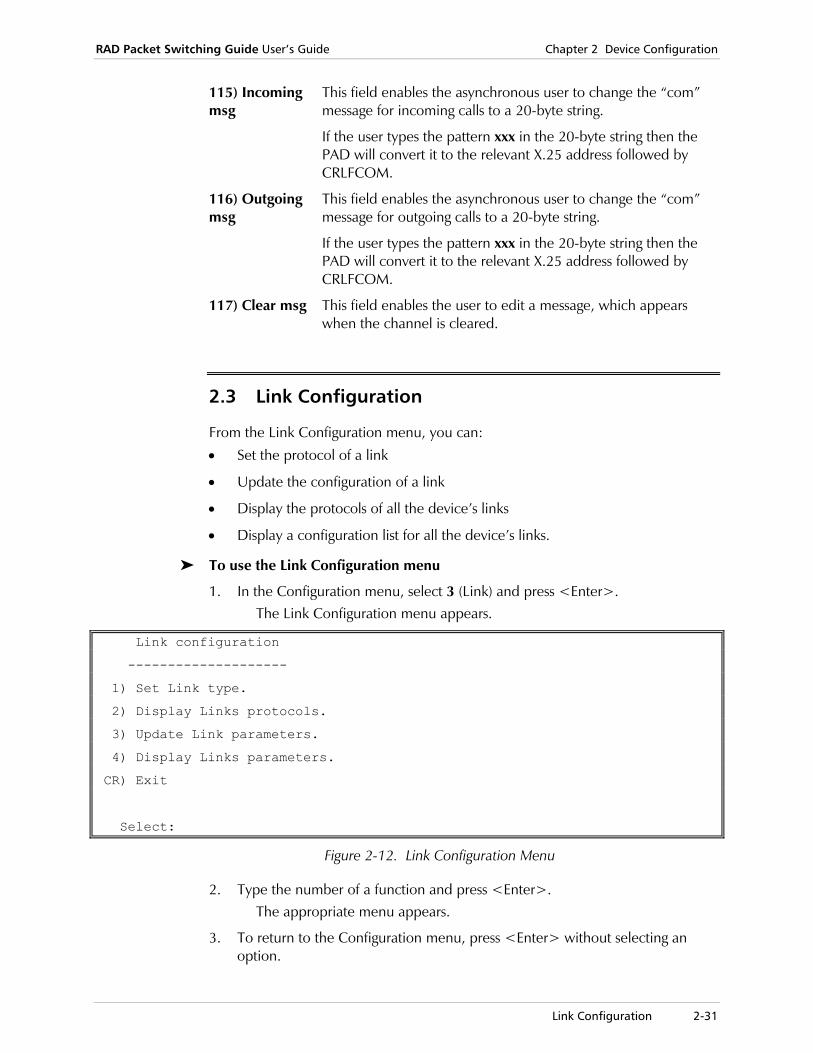
RAD Packet Switching Guide User’s Guide Chapter 2 Device Configuration
Link Configuration 2-31
115) Incoming msg
This field enables the asynchronous user to change the “com” message for incoming calls to a 20-byte string.
If the user types the pattern xxx in the 20-byte string then the PAD will convert it to the relevant X.25 address followed by CRLFCOM.
116) Outgoing msg
This field enables the asynchronous user to change the “com” message for outgoing calls to a 20-byte string.
If the user types the pattern xxx in the 20-byte string then the PAD will convert it to the relevant X.25 address followed by CRLFCOM.
117) Clear msg This field enables the user to edit a message, which appears when the channel is cleared.
2.3 Link Configuration
From the Link Configuration menu, you can:
• Set the protocol of a link
• Update the configuration of a link
• Display the protocols of all the device’s links
• Display a configuration list for all the device’s links.
To use the Link Configuration menu
1. In the Configuration menu, select 3 (Link) and press <Enter>. The Link Configuration menu appears.
Link configuration
--------------------
1) Set Link type.
2) Display Links protocols.
3) Update Link parameters.
4) Display Links parameters.
CR) Exit
Select:
Figure 2-12. Link Configuration Menu
2. Type the number of a function and press <Enter>. The appropriate menu appears.
3. To return to the Configuration menu, press <Enter> without selecting an option.

Chapter 2 Device Configuration RAD Packet Switching Guide User’s Guide
2-32 Link Configuration
Set Link Type Use the Set Link Type function to set the protocol type for a specific link.
1. In the Configuration menu, select 3 (Link) and press <Enter>. The Link Configuration menu appears.
2. Select 1 (Set link type) and press <Enter>. A list of links and their corresponding protocol types appears.
Link 1 2 3 4 5 6 7 8 ------ -----|-----|-----|-----|-----|-----|-----|----- Prot X.25 | FR |HDLC |STM4 | MPE |ETHER|ASYNC| PPP Enter Link number to SET:
Figure 2-13. List of Links and Their Protocol Types
3. Type the link number you want and press <Enter>. The Link Types menu appears.
Link types ------------ 1) X.25 2) FRAME RELAY 3) HDLC 4) SDLC 5) ASYNC 6) STM4/4HS 7) STM8/8HS 8) STM16/16HS 9) STM24/24HS 10) MPE (Multi Point Encapsulator) 11) ETHERNET 12) PPP CR) Exit Select:
Figure 2-14. Link Types Menu
The Link Types screen may have more or fewer options, depending on the specific device and/or its jumper configuration.
4. Select the link type and press <Enter>. For descriptions of the available protocols, see Chapter 7, Protocols.
5. Select another link number to set or press <Enter> to return to the Link Configuration menu.
Note

RAD Packet Switching Guide User’s Guide Chapter 2 Device Configuration
Link Configuration 2-33
Update Link Parameters Use the Update Link Parameters function to display and change the configuration parameters of a device link. The link parameters vary according to the specific protocol.
To update a link’s configuration:
1. In the Configuration menu, select 3 (Link) and press <Enter>. The Link Configuration menu appears.
2. Select 3 (Update Link Parameters) and press <Enter>. A list of links and their corresponding protocol types appears.
3. Type the number of the link you want and press <Enter>. A link configuration screen (according to specific link type) appears. For more details, see the specific link type parameters descriptions later in this section.
• A link that is set as an ASYNC Link will function as a PAD channel. The channel number is its link number multiplied by 100. For example, for link number 5, the PAD channel number is 500
• To configure a SLIP or PPP link, set the link type as Async • To configure this link, use the Channel Configuration menu (see Channel
Configuration on page 2-3).
Display Links Protocols Use the Display Links Protocols function to display the current protocols for all the links.
To display the links’ protocols:
1. In the Link Configuration menu, select 2 (Display Links Protocols) and press <Enter>.
A list of links and their corresponding protocol types appears.
Link 1 2 3 4 5 6 7 8
------ -----|-----|-----|-----|-----|-----|-----|-----
Prot X.25 | FR |HDLC |STM4 | MPE |ETHER|ASYNC| PPP
Press <CR> to continue
Figure 2-15. List of Links and Their Protocol Types
2. Press <Enter> to return to the Link Configuration menu.
Note
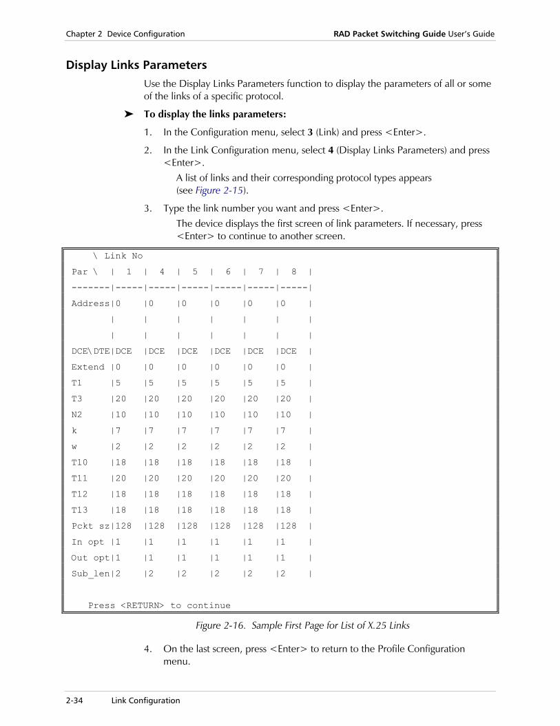
Chapter 2 Device Configuration RAD Packet Switching Guide User’s Guide
2-34 Link Configuration
Display Links Parameters Use the Display Links Parameters function to display the parameters of all or some of the links of a specific protocol.
To display the links parameters:
1. In the Configuration menu, select 3 (Link) and press <Enter>.
2. In the Link Configuration menu, select 4 (Display Links Parameters) and press <Enter>.
A list of links and their corresponding protocol types appears (see Figure 2-15).
3. Type the link number you want and press <Enter>. The device displays the first screen of link parameters. If necessary, press <Enter> to continue to another screen.
\ Link No
Par \ | 1 | 4 | 5 | 6 | 7 | 8 |
-------|-----|-----|-----|-----|-----|-----|
Address|0 |0 |0 |0 |0 |0 |
| | | | | | |
| | | | | | |
DCE\DTE|DCE |DCE |DCE |DCE |DCE |DCE |
Extend |0 |0 |0 |0 |0 |0 |
T1 |5 |5 |5 |5 |5 |5 |
T3 |20 |20 |20 |20 |20 |20 |
N2 |10 |10 |10 |10 |10 |10 |
k |7 |7 |7 |7 |7 |7 |
w |2 |2 |2 |2 |2 |2 |
T10 |18 |18 |18 |18 |18 |18 |
T11 |20 |20 |20 |20 |20 |20 |
T12 |18 |18 |18 |18 |18 |18 |
T13 |18 |18 |18 |18 |18 |18 |
Pckt sz|128 |128 |128 |128 |128 |128 |
In opt |1 |1 |1 |1 |1 |1 |
Out opt|1 |1 |1 |1 |1 |1 |
Sub_len|2 |2 |2 |2 |2 |2 |
Press <RETURN> to continue
Figure 2-16. Sample First Page for List of X.25 Links
4. On the last screen, press <Enter> to return to the Profile Configuration menu.

RAD Packet Switching Guide User’s Guide Chapter 2 Device Configuration
Link Configuration 2-35
X.25 Link Parameters The X.25 Link n Configuration screen contains the X.25 link configuration parameters. The number of the link appears in the screen title (n).
These parameters determine the following characteristics:
• X.25 network address of the device (parameter 1)
• Logical appearance of the device toward the X.25 network (parameter 2)
• LAPB and X.25 mode (parameter 3)
• LAPB parameters T1, T3, N2, k (parameters 4 through 13)
• Configuration of logical groups and logical channels (parameters 17 through 21).
X.25 Link 1 configuration
----------------------------------------
1) Address ............... [0 ] 17) LGN ...................... [0]
2) DCE (1) / DTE (0)...... [1 ] 18) Lowest LCN (LIC) ......... [1]
3) Extended mode ......... [0 ] 19) Amount of Incoming LCNs .. [5]
4) T1 .................... [5 ] 20) Amount of Two Way LCNs ... [5]
5) T3 .................... [20 ] 21) Amount of Outgoing LCNs .. [5]
6) N2 .................... [10 ] 22) Internal Clock ........... [0]
7) k ..................... [7 ] 23) LINE option .............. [1024]
8) w ..................... [2 ] 24) Segment Size.............. [128]
9) T10 ................... [18 ] 25) Xid num .................. [0]
10) T11 ................... [20 ] 26) NUI Group ID ............. [0]
11) T12 ................... [18 ] 27) Physical interface option. [0]
12) T13 ................... [18 ] 28) X.25 Acknowledge Counter . [1]
13) Packet size ........... [128 ] 29) X.25 Acknowledge Timer ... [0]
14) In call options ....... [1 ] 30) LAPB Acknowledge Counter . [1]
15) Out call options ...... [1 ] 31) LAPB Acknowledge Timer ... [0]
16) Subaddress length ..... [2 ] 32) CUG subscription ......... [5]
S) Save
CR) Exit
Select:
Figure 2-17. Default X.25 Link Configuration Screen
Chapter 2 Device Configuration RAD Packet Switching Guide User’s Guide
2-36 Link Configuration
1) Address X.25 network calling address of the device. Possible values:
0 No change in Calling Address.
Up to 15 digits Valid X.25 address.
If this parameter is 0: • If device operates as a PAD, no Calling Address is added to outgoing packets. • If device operates as a switch, the packet is forwarded with its incoming Calling
Address.
2) DCE (1) /DTE (0)
Current operating type of this device. Possible values:
0 LAPB and X.25 layers are set to DTE.
1 LAPB and X.25 layers are set to DCE (default).
2 LAPB layer is set to DTE and X.25 layer is set to DCE.
3 LAPB layer is set to DCE and X.25 layer is set to DTE.
3) Extended Mode
Frame numbering mode of the link. ·
• Modulo-8 is used for packet window size range of 1 to 7.
• Modulo-128 is used for packet window size range of 1 to 127.Possible values:
0 LAPB and X.25 layers are set to basic (modulo-8) mode (default).
1 LAPB layer is set to extended (modulo-128) mode and X.25 layer is set to modulo-8 mode.
2 LAPB layer is set to modulo-8 mode and X.25 layer is set to modulo-128 mode.
3 LAPB and X.25 layers are set to modulo-128 mode.
4) T1 Interval between the end of the transmission of a frame and the receipt of an acknowledgement. The T1 timer protects against the loss of frames in the path that connects the device PADs to the X.25 network. Possible values:
0 LAPB T1 timer is disabled.
1 - 255 Number of seconds. The default value is 5.
• T1 functions are covered by ITU Rec. X.25 • The value of the DTE timer may be different from the value of the network timer.
Note
Notes

RAD Packet Switching Guide User’s Guide Chapter 2 Device Configuration
Link Configuration 2-37
5) T3 Interval before the link level reports to the packet level that the link is down. All virtual calls on this link are then cleared and PVCs are reset. Possible values:
0 LAPB T3 timer is disabled.
1 - 255 Number of seconds. The default value is 20.
• T3 functions are covered by ITU Rec. X.25 • The value of T3 must be much greater than the value of T1.
6) N2 Maximum number of times that the PAD retransmits an unacknowledged packet. Possible values:
0 The PAD resets the link when it detects an unacknowledged packet.
1 - 255 Number of retransmissions. The default value is 10.
N2 functions are covered by ITU Rec. X.25.
7) k Maximum number of link level information frames that may remain unacknowledged at any given time on the link. Possible values:
1 - 7 For LAPB operation in basic mode.
1 - 127 For LAPB operation in extended mode. The default value is 7.
• The default value of 7 is supported by all X.25 networks • Parameter 3 (Extended Mode) must be set to values 1 or 3.
8) w Maximum number of packets that may remain unacknowledged at any given time for each X.25 call from the device. Possible values:
1 - 7 For X.25 operation in basic mode.
1 - 127 For X.25 operation in extended mode. The default value is 2.
Parameter 3 (Extended Mode) must be set to values 2 or 3.
Notes
Note
Notes
Note
Chapter 2 Device Configuration RAD Packet Switching Guide User’s Guide
2-38 Link Configuration
9) T10 Maximum time the X.25 DCE waits for confirmation after sending a restart indication to the X.25 DTE, before it is ready to receive new control packets. Possible values:
0 No waiting.
1 - 255 Number of seconds. The default value is 18.
ITU recommended value is 60 seconds.
10) T11 Maximum time the X.25 DCE waits for confirmation after sending an incoming call indication to the X.25 DTE, before clearing the call, if the call is unacknowledged. Possible values:
0 No waiting.
1 - 255 Number of seconds. The default value is 20.
ITU recommended value is 180 seconds.
11) T12 Maximum time the X.25 DCE waits for confirmation after sending a reset indication to the X.25 DTE. After T12 expires a second time, the switched virtual call is cleared. For PVCs, the X.25 DCE will be ready to receive new call setup packets. Possible values:
0 No waiting.
1 - 255 Number of seconds. The default value is 18.
ITU recommended value is 60 seconds.
12) T13 Maximum time the X.25 DCE waits for confirmation after sending a “clear” indication to the X.25 DTE. After T13 expires a second time, the X.25 DCE will be ready for call setup. Possible values:
0 No waiting.
1 - 255 Number of seconds. The default value is 18.
ITU recommended value is 60 seconds.
Note
Note
Note
Note

RAD Packet Switching Guide User’s Guide Chapter 2 Device Configuration
Link Configuration 2-39
13) Packet Size Maximum number of bytes that the device inserts into a network-bound packet or accepts in an in-bound packet. Possible values:
0 - 4096 Number of bytes. Frequent values are 128, 256, 512, 1024, 2048 and 4096.The default value is 128.
14) In Call Options
Options to control the incoming calls on the selected link. Possible values:
0 No options.
1 Fast select acceptance (default).
2 Reverse charge acceptance.
4 Subaddress in Call User Data (CUD).
8 Protocol ID (PID) running over X.25 is not included in the frame.
16 Assume that PVC is down if the link is sync. The PVC will be up after the device receives a network operational message.
32 Reset Response 2 second delay. According to the X.25 standard, after receiving a Reset Request message, the Reset Confirm (response) should be sent within the defined period of time (seconds), in End-to-End mode.
XXX Any combination of the above values.
15) Out Call Options
Options to control the outgoing calls on the selected link. Possible values:
0 No options.
1 Don't add calling and called addresses in call accept packet (default).
2 Call request spread enabled.
4 Add source link number to called address.
8 Don't change calling address.
16 Add facility length field to call accept packet. This option is relevant when call accept packet does not include a facility field (otherwise, facility length field is added automatically).
XX Any combination of the above values.
16) Subaddress Length
Number of digits in the subaddress. The subaddress is taken from the called address or from the user data field in order to specify the local asynchronous channel. Possible values:
1 - 5 Number of digits. The default value is 2.

Chapter 2 Device Configuration RAD Packet Switching Guide User’s Guide
2-40 Link Configuration
17) LGN Logical Group Number - ID of a group of PVCs running on the selected link. Possible values:
0 - 15 Logical Group Number. The default value is 0.
18) Lowest LCN (LIC)
Lowest In Coming Logical Channel (LCN). Possible values:
0 - 255 The lowest possible LCN logical channel number. The default value is 1.
19) Amount of Incoming LCNs
Number of incoming logical channels. Possible values:
0 - 255 Number of LCNs. The default value is 5.
20) Amount of Two Way LCNs
Number of incoming and outgoing logical channels. Possible values:
0 - 255 Number of LCNs. The default value is 5.
21) Amount of Outgoing LCNs
Number of outgoing logical channels. Possible values:
0 - 255 Number of LCNs. The default value is 5.
For parameters 18 to 21: • The total number of LCNs (incoming, two way and outgoing) of all the device’s
links may not exceed the device’s Maximum LCN. You define Maximum LCN through the Systems Parameter Configuration menu, parameter 12. For more details, see System Parameters Configuration on page 2-92
• The Incoming LCNs, Two way LCNs and Outgoing LCNs are sequential. According to the default values, the lowest LCN (LIC) is 1, the incoming LCNs are 1 through 5, the two way LCNs are 6 through 10 and the Outgoing LCNs are 11 through 15. For example, if only 6 LCNs are available and all of them should be two way LCNs, the parameters should be set as follows Lowest LCN (LIC) is set to 1. Number of Incoming LCNs is set to 0. Number of Two way LCNs is set to 6. Number of Outgoing LCNs is set to 0. For further clarification, see Figure 7-4, Assignment of Logical Channels.
Note
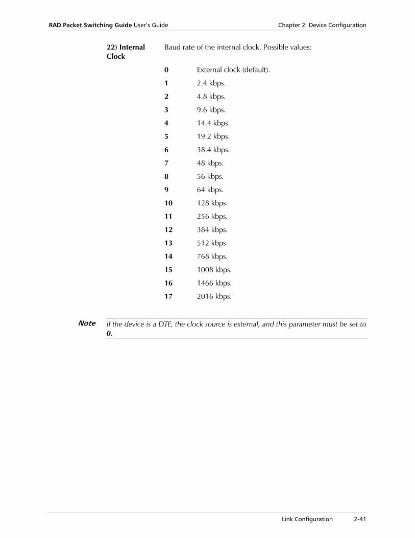
RAD Packet Switching Guide User’s Guide Chapter 2 Device Configuration
Link Configuration 2-41
22) Internal Clock
Baud rate of the internal clock. Possible values:
0 External clock (default).
1 2.4 kbps.
2 4.8 kbps.
3 9.6 kbps.
4 14.4 kbps.
5 19.2 kbps.
6 38.4 kbps.
7 48 kbps.
8 56 kbps.
9 64 kbps.
10 128 kbps.
11 256 kbps.
12 384 kbps.
13 512 kbps.
14 768 kbps.
15 1008 kbps.
16 1466 kbps.
17 2016 kbps.
If the device is a DTE, the clock source is external, and this parameter must be set to 0.
Note

Chapter 2 Device Configuration RAD Packet Switching Guide User’s Guide
2-42 Link Configuration
23) LINE Options
Options that enable the device to work with dial-up modems. The dial-up modem must have the option of dialing a stored number by raising the DTR signal on the RS-232 line (in modem’s synchronous mode). Possible values:
0 No options.
1 - 255 Number of minutes that the dial-up link is connected, while all sessions are closed through the dial-up link. When this time expires, the dial-up link disconnects.
256 Control the DTR operation on the dial link (must be set on dial-up links also).
512 Dialed link disconnects after the leased line is restored, enabling users to reopen a session through the leased line.
1024 DTR is on permanently on this link (usually a leased line) (default).
2048 DTR is off permanently on this link.
XXXX Any combination of the above values totaling 256 - 1022.Valid combinations of these options.
24) Segment Size
Size of a segment used for charging/billing calls. Possible values:
1 - 128 Number of bytes. The default value is 128.
25) XID Number
Specific Exchange ID (XID) entry number. This parameter is used if X.32 dialing facility operates on the selected link (see X.32 Support on page 2-141). Possible values:
0 X.32 facility is disabled (default).
1 - 200 Predefined XID entry number.
26) NUI Group ID
Specific Network User ID (NUI) Group ID number. This parameter is used if the NUI security facility operates on the selected link (see NUI Configuration on page 2-111). Possible values:
0 NUI facility is disabled (default).
1 - 200 Predefined NUI Group ID number.

RAD Packet Switching Guide User’s Guide Chapter 2 Device Configuration
Link Configuration 2-43
27) Physical Interface Option
ACD interface baud rate. The ACD interface enables the device to link to a DDS (AT&T) network. Possible values:
0 No option.
1 4.8 kbps.
2 9.6 kbps.
3 19.2 kbps.
4 56 kbps.
28) X.25 Acknowledge Counter
Maximum number of data frames sent before transmitting an acknowledgement (for X.25 layer). Possible values:
1 - 128 Number of data frames. The default value is 1.
29) X.25 Acknowledge Timer
Maximum interval until transmitting an acknowledgement (for X.25 layer). Possible values:
0 - 255 Number of seconds. The default value is 0.
30) LAPB Acknowledge Counter
Maximum number of data frames sent before transmitting an acknowledgement (for LAPB layer). Possible values:
1 - 128 Number of seconds. The default value is 1.
31) LAPB Acknowledge Timer
Maximum interval until transmitting an acknowledgement (for LAPB layer). Possible values:
0 - 255 Number of seconds. The default value is 0.
32) CUG Subscription
Type of Closed User Group (CUG) configuration used on the selected link (see CUG Configuration on page 2-44). Possible values:
0 No CUG.
1 CUG with preferential.
2 CUG/OA with preferential.
3 CUG/IA with preferential.
4 CUG/OA/IA with preferential.
5 CUG/OA/IA without preferential (transparent) (default).
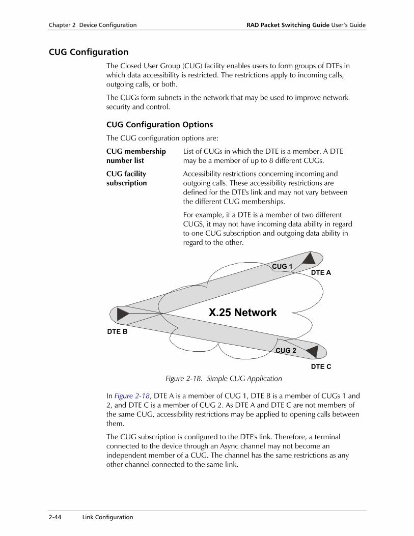
Chapter 2 Device Configuration RAD Packet Switching Guide User’s Guide
2-44 Link Configuration
CUG Configuration The Closed User Group (CUG) facility enables users to form groups of DTEs in which data accessibility is restricted. The restrictions apply to incoming calls, outgoing calls, or both.
The CUGs form subnets in the network that may be used to improve network security and control.
CUG Configuration Options
The CUG configuration options are:
CUG membership number list
List of CUGs in which the DTE is a member. A DTE may be a member of up to 8 different CUGs.
CUG facility subscription
Accessibility restrictions concerning incoming and outgoing calls. These accessibility restrictions are defined for the DTE's link and may not vary between the different CUG memberships.
For example, if a DTE is a member of two different CUGS, it may not have incoming data ability in regard to one CUG subscription and outgoing data ability in regard to the other.
X.25 Network
DTE A
DTE C
DTE B
CUG 1
CUG 2
Figure 2-18. Simple CUG Application
In Figure 2-18, DTE A is a member of CUG 1, DTE B is a member of CUGs 1 and 2, and DTE C is a member of CUG 2. As DTE A and DTE C are not members of the same CUG, accessibility restrictions may be applied to opening calls between them.
The CUG subscription is configured to the DTE's link. Therefore, a terminal connected to the device through an Async channel may not become an independent member of a CUG. The channel has the same restrictions as any other channel connected to the same link.
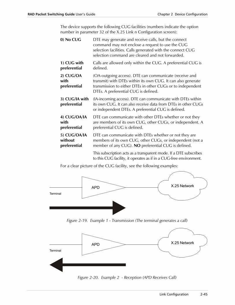
RAD Packet Switching Guide User’s Guide Chapter 2 Device Configuration
Link Configuration 2-45
The device supports the following CUG facilities (numbers indicate the option number in parameter 32 of the X.25 Link n Configuration screen):
0) No CUG DTE may generate and receive calls, but the connect command may not enclose a request to use the CUG selection facilities. Calls generated with the connect CUG selection command are cleared and not forwarded.
1) CUG with preferential
Calls are allowed only within the CUG. A preferential CUG is defined.
2) CUG/OA with preferential
(OA-outgoing access). DTE can communicate (receive and transmit) with DTEs within its own CUG. It can also generate transmission to either DTEs in other CUGs or to independent DTEs. A preferential CUG is defined.
3) CUG/IA with preferential
(IA-incoming access). DTE can communicate with DTEs within its own CUG. It can also receive data from DTEs in other CUGs or independent DTEs. A preferential CUG is defined.
4) CUG/OA/IA with preferential
DTE can communicate with other DTEs whether or not they are members of its own CUG, other CUGs, or independent. A preferential CUG is defined.
5) CUG/OA/IA without preferential
DTE can communicate with DTEs whether or not they are members of its own CUG, other CUGs, or independent (not a member of any CUG). NO preferential CUG is defined.
This subscription acts as a transparent mode. If a DTE subscribes to this CUG facility, it operates as if in a CUG-free environment.
For a clear picture of the CUG facility, see the following examples:
X.25 NetworkAPDTerminal
Figure 2-19. Example 1 - Transmission (The terminal generates a call)
X.25 NetworkAPDTerminal
Figure 2-20. Example 2 - Reception (APD Receives Call)
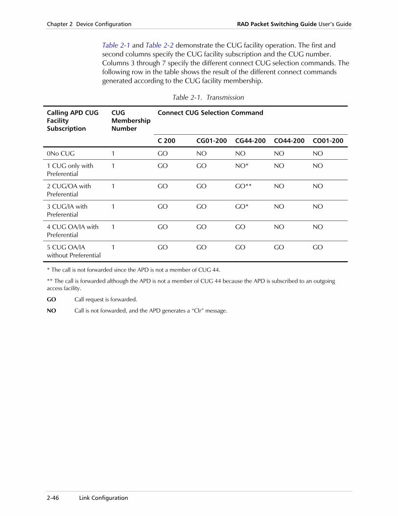
Chapter 2 Device Configuration RAD Packet Switching Guide User’s Guide
2-46 Link Configuration
Table 2-1 and Table 2-2 demonstrate the CUG facility operation. The first and second columns specify the CUG facility subscription and the CUG number. Columns 3 through 7 specify the different connect CUG selection commands. The following row in the table shows the result of the different connect commands generated according to the CUG facility membership.
Table 2-1. Transmission
Calling APD CUG Facility Subscription
CUG Membership Number
Connect CUG Selection Command
C 200 CG01-200 CG44-200 CO44-200 CO01-200
0No CUG 1 GO NO NO NO NO
1 CUG only with Preferential
1 GO GO NO* NO NO
2 CUG/OA with Preferential
1 GO GO GO** NO NO
3 CUG/IA with Preferential
1 GO GO GO* NO NO
4 CUG OA/IA with Preferential
1 GO GO GO NO NO
5 CUG OA/IA without Preferential
1 GO GO GO GO GO
* The call is not forwarded since the APD is not a member of CUG 44.
** The call is forwarded although the APD is not a member of CUG 44 because the APD is subscribed to an outgoing access facility.
GO Call request is forwarded.
NO Call is not forwarded, and the APD generates a “Clr” message.
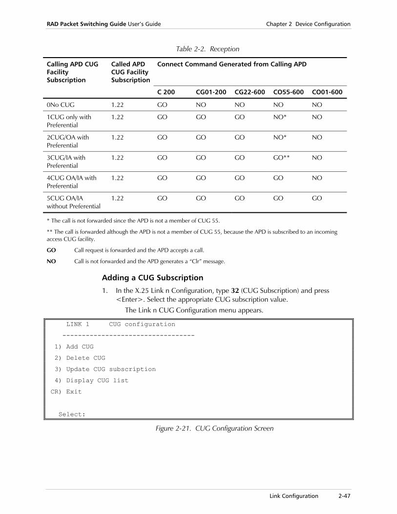
RAD Packet Switching Guide User’s Guide Chapter 2 Device Configuration
Link Configuration 2-47
Table 2-2. Reception
Calling APD CUG Facility Subscription
Called APD CUG Facility Subscription
Connect Command Generated from Calling APD
C 200 CG01-200 CG22-600 CO55-600 CO01-600
0No CUG 1.22 GO NO NO NO NO
1CUG only with Preferential
1.22 GO GO GO NO* NO
2CUG/OA with Preferential
1.22 GO GO GO NO* NO
3CUG/IA with Preferential
1.22 GO GO GO GO** NO
4CUG OA/IA with Preferential
1.22 GO GO GO GO NO
5CUG OA/IA without Preferential
1.22 GO GO GO GO GO
* The call is not forwarded since the APD is not a member of CUG 55.
** The call is forwarded although the APD is not a member of CUG 55, because the APD is subscribed to an incoming access CUG facility.
GO Call request is forwarded and the APD accepts a call.
NO Call is not forwarded and the APD generates a “Clr” message.
Adding a CUG Subscription
1. In the X.25 Link n Configuration, type 32 (CUG Subscription) and press <Enter>. Select the appropriate CUG subscription value.
The Link n CUG Configuration menu appears.
LINK 1 CUG configuration
----------------------------------
1) Add CUG
2) Delete CUG
3) Update CUG subscription
4) Display CUG list
CR) Exit
Select:
Figure 2-21. CUG Configuration Screen

Chapter 2 Device Configuration RAD Packet Switching Guide User’s Guide
2-48 Link Configuration
2. Select 1 (Add CUG) and press <Enter>. A list of existing CUG subscription numbers appears, according to the order they were added. The first CUG on the list is the preferential CUG.
Link 1
----------
CUG LIST: 10,1,4,2
Enter group number to ADD:
Figure 2-22. List of Existing CUGS
3. Type a new CUG number and press <Enter>.
4. To set the new CUG subscription value, select 3 (Update CUG subscription) and press <Enter>.
The Link n CUG Subscription screen appears.
Link 1 CUG Subscription
--------------------------------------------
Current value [0]
Possible values:
0 - NO CUG
1 - CUG with preferential
2 - CUG/OA with preferential
3 - CUG/IA with preferential
4 - CUG/OA/IA with preferential
5 - CUG/OA/IA without preferential (transparent)
Enter new subscription value:
Figure 2-23. Link n CUG Subscription Screen
5. Select the number of the new CUG subscription’s value and press <Enter>.
Updating a CUG Subscription
1. In the X.25 Link n Configuration, type 32 (CUG Subscription) and press <Enter>. Select the appropriate CUG subscription value.
The Link n CUG Configuration menu appears.
2. Select 3 (Update CUG subscription) and press <Enter>. A list of existing CUG subscription numbers appears, according to the order they were added. The first CUG on the list is the preferential CUG.
3. Type the number of the CUG subscription you want. The Link n CUG Subscription screen appears.
4. Select the appropriate CUG subscription value and press <Enter>. For a description of these values, see CUG Configuration Options on page 2-44.
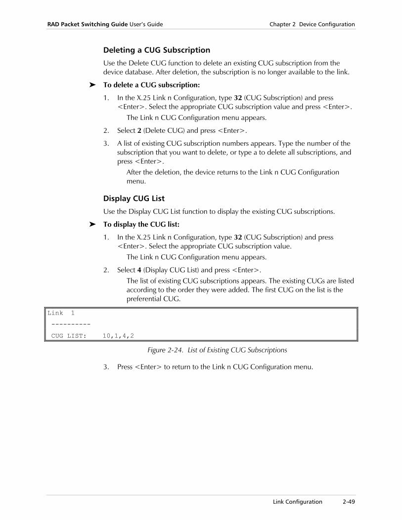
RAD Packet Switching Guide User’s Guide Chapter 2 Device Configuration
Link Configuration 2-49
Deleting a CUG Subscription
Use the Delete CUG function to delete an existing CUG subscription from the device database. After deletion, the subscription is no longer available to the link.
To delete a CUG subscription:
1. In the X.25 Link n Configuration, type 32 (CUG Subscription) and press <Enter>. Select the appropriate CUG subscription value and press <Enter>.
The Link n CUG Configuration menu appears.
2. Select 2 (Delete CUG) and press <Enter>.
3. A list of existing CUG subscription numbers appears. Type the number of the subscription that you want to delete, or type a to delete all subscriptions, and press <Enter>.
After the deletion, the device returns to the Link n CUG Configuration menu.
Display CUG List
Use the Display CUG List function to display the existing CUG subscriptions.
To display the CUG list:
1. In the X.25 Link n Configuration, type 32 (CUG Subscription) and press <Enter>. Select the appropriate CUG subscription value.
The Link n CUG Configuration menu appears.
2. Select 4 (Display CUG List) and press <Enter>. The list of existing CUG subscriptions appears. The existing CUGs are listed according to the order they were added. The first CUG on the list is the preferential CUG.
Link 1
----------
CUG LIST: 10,1,4,2
Figure 2-24. List of Existing CUG Subscriptions
3. Press <Enter> to return to the Link n CUG Configuration menu.
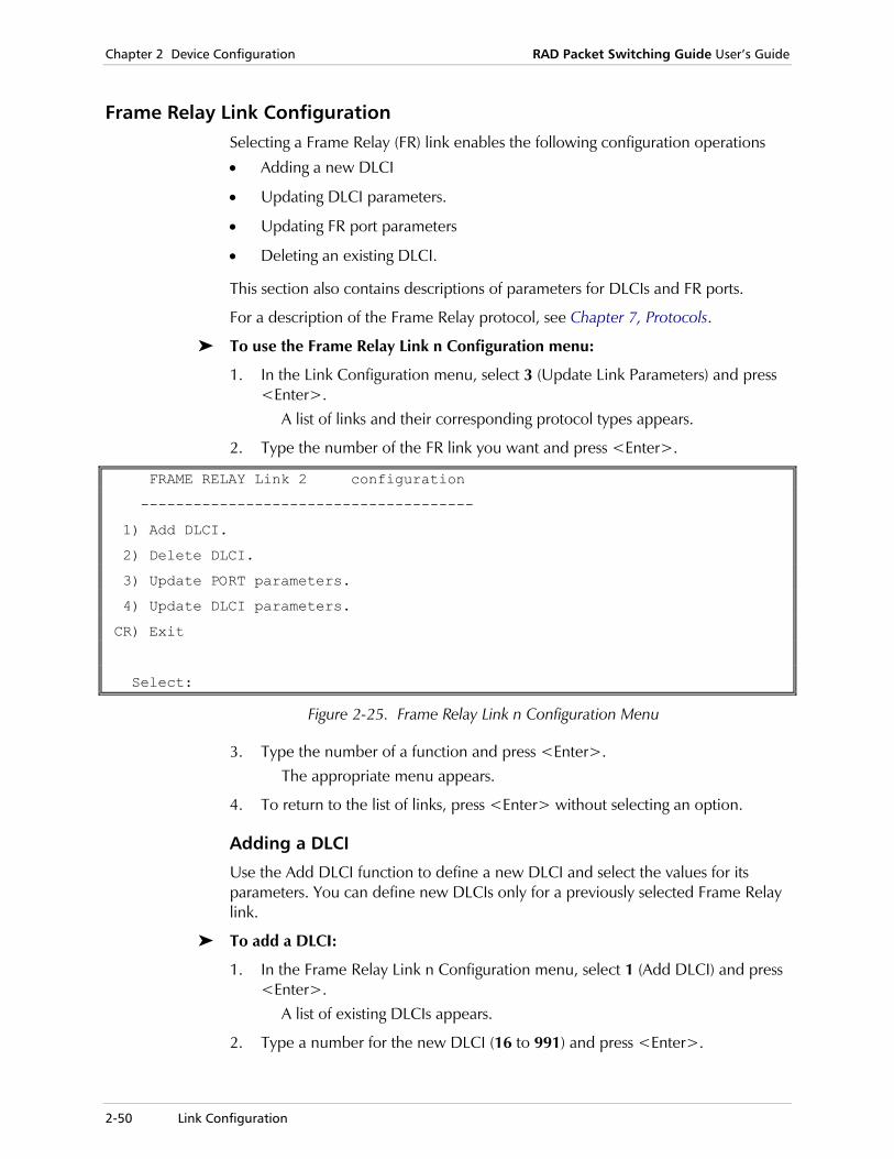
Chapter 2 Device Configuration RAD Packet Switching Guide User’s Guide
2-50 Link Configuration
Frame Relay Link Configuration Selecting a Frame Relay (FR) link enables the following configuration operations
• Adding a new DLCI
• Updating DLCI parameters.
• Updating FR port parameters
• Deleting an existing DLCI.
This section also contains descriptions of parameters for DLCIs and FR ports.
For a description of the Frame Relay protocol, see Chapter 7, Protocols.
To use the Frame Relay Link n Configuration menu:
1. In the Link Configuration menu, select 3 (Update Link Parameters) and press <Enter>.
A list of links and their corresponding protocol types appears.
2. Type the number of the FR link you want and press <Enter>.
FRAME RELAY Link 2 configuration
--------------------------------------
1) Add DLCI.
2) Delete DLCI.
3) Update PORT parameters.
4) Update DLCI parameters.
CR) Exit
Select:
Figure 2-25. Frame Relay Link n Configuration Menu
3. Type the number of a function and press <Enter>. The appropriate menu appears.
4. To return to the list of links, press <Enter> without selecting an option.
Adding a DLCI
Use the Add DLCI function to define a new DLCI and select the values for its parameters. You can define new DLCIs only for a previously selected Frame Relay link.
To add a DLCI:
1. In the Frame Relay Link n Configuration menu, select 1 (Add DLCI) and press <Enter>.
A list of existing DLCIs appears.
2. Type a number for the new DLCI (16 to 991) and press <Enter>.

RAD Packet Switching Guide User’s Guide Chapter 2 Device Configuration
Link Configuration 2-51
Updating a DLCI
Use the Update DLCI Parameters function to change the parameter values for a new or existing DLCI.
To update a DLCI:
1. In the Frame Relay Link n Configuration menu, select 4 (Update DLCI Parameters).
The DLCI xx Link n menu appears. The DLCI number and the link number are indicated in the menu title.
DLCI 16 Link 2
------------------------------------------
1) Update DLCI configuration.
2) Update X25 configuration.
CR) Exit
Select:
Figure 2-26. DLCI xx Link n Menu
2. Select 1 (Update DLCI Configuration) and press <Enter>. The DLCI xx Link n Configuration screen appears. When you configure a DLCI for the first time, this screen displays the default values. For more details, see DLCI Parameters on page 2-53.
3. To configure a specific parameter, type its number and press <Enter>. The device prompts you for the new parameter value.
4. Type a new parameter value and press <Enter>. The new value appears in the value column.
5. Type S and press <Enter> to save the new configuration.
To cancel the changes you made, exit without saving the new values.
6. To return to the DLCI xx Link n menu, press <Enter> without making any parameter selection.
After the new parameter values are saved, the device continues to operate in accordance with the previous parameters values. The new parameters values will take effect the next time the device is reset or turned on!!!
Note
Note
Chapter 2 Device Configuration RAD Packet Switching Guide User’s Guide
2-52 Link Configuration
Updating Frame Relay Port Parameters
Use the Update Port Parameters function to view and change the parameters of the selected Frame Relay link’s port.
To update FR port parameters:
1. In the Frame Relay Link n Configuration menu, select 3 (Update Port Parameters).
The Frame Relay Port n screen appears. The port number is indicated in the menu title. When you configure a FR port for the first time, this screen displays the default values. For more details, see Frame Relay PORT Parameters on page 2-57.
2. To configure a specific parameter, type its number and press <Enter>. The device prompts you for the new parameter value.
3. Type a new parameter value and press <Enter>. The new value appears in the value column.
4. Type S and press <Enter> to save the new configuration.
To cancel the changes you made, exit without saving the new values.
5. To return to the Frame Relay Link n Configuration menu, press <Enter> without making any parameter selection.
Deleting a DLCI
Use the Delete DLCI function to delete an existing DLCI from the selected Frame Relay link.
To delete a DLCI:
1. In the Frame Relay Link n Configuration menu, select 2 (Delete DLCI) and press <Enter>.
2. A list of existing DLCI numbers appears. Type the number (16 - 991) of the DLCI that you want to delete and press <Enter>.
After the deletion, the device returns to the Frame Relay Link n Configuration menu.
Note

RAD Packet Switching Guide User’s Guide Chapter 2 Device Configuration
Link Configuration 2-53
DLCI Parameters The DLCI xx Link n Configuration screen contains the DLCI configuration parameters. The numbers of the DLCI (xx) and the link (n) appear in the screen title.
These parameters determine the following characteristics:
• Frame Relay DLCI encapsulation protocol (parameter 1)
• Destination DLCI for non-encapsulation Frame Relay protocol DLCIs (parameter 2)
• Committed Information Rate (CIR) parameters for transmission and reception (parameters 3 through 9)
• Funnel ID attached to the DLCI (parameter 10)
• Transmission priority (parameter 11)
• ISDN destination ID (parameter 12).
DLCI 16 Link 2 configuration
------------------------------------------
1) Encapsulation Type ................ [2 ]
2) Destination Id .................... [0:0 ]
3) Backup DLCI ....................... [0:0 ]
4) Tx Tc (1/10 Sec) .................. [10 ]
5) Tx Bc (Bytes per Tx Tc) ........... [65000]
6) Tx Be (Bytes per Tx Tc) ........... [65000]
7) Rx Tc (1/10 Sec) .................. [10 ]
8) Rx Bc (Bytes per Rx Tc) ........... [65000]
9) Rx Be (Bytes per Rx Tc) ........... [65000]
10) Funnel id ......................... [0 ]
11) Tx Priority ....................... [0 ]
12) ISDN Destination .................. [0 ]
S) Save
CR) Exit
Select:
Figure 2-27. DLCI x Link n Configuration Screen
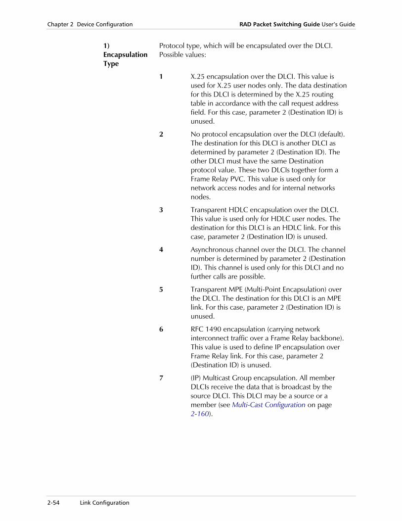
Chapter 2 Device Configuration RAD Packet Switching Guide User’s Guide
2-54 Link Configuration
1) Encapsulation Type
Protocol type, which will be encapsulated over the DLCI. Possible values:
1 X.25 encapsulation over the DLCI. This value is used for X.25 user nodes only. The data destination for this DLCI is determined by the X.25 routing table in accordance with the call request address field. For this case, parameter 2 (Destination ID) is unused.
2 No protocol encapsulation over the DLCI (default). The destination for this DLCI is another DLCI as determined by parameter 2 (Destination ID). The other DLCI must have the same Destination protocol value. These two DLCIs together form a Frame Relay PVC. This value is used only for network access nodes and for internal networks nodes.
3 Transparent HDLC encapsulation over the DLCI. This value is used only for HDLC user nodes. The destination for this DLCI is an HDLC link. For this case, parameter 2 (Destination ID) is unused.
4 Asynchronous channel over the DLCI. The channel number is determined by parameter 2 (Destination ID). This channel is used only for this DLCI and no further calls are possible.
5 Transparent MPE (Multi-Point Encapsulation) over the DLCI. The destination for this DLCI is an MPE link. For this case, parameter 2 (Destination ID) is unused.
6 RFC 1490 encapsulation (carrying network interconnect traffic over a Frame Relay backbone). This value is used to define IP encapsulation over Frame Relay link. For this case, parameter 2 (Destination ID) is unused.
7 (IP) Multicast Group encapsulation. All member DLCIs receive the data that is broadcast by the source DLCI. This DLCI may be a source or a member (see Multi-Cast Configuration on page 2-160).
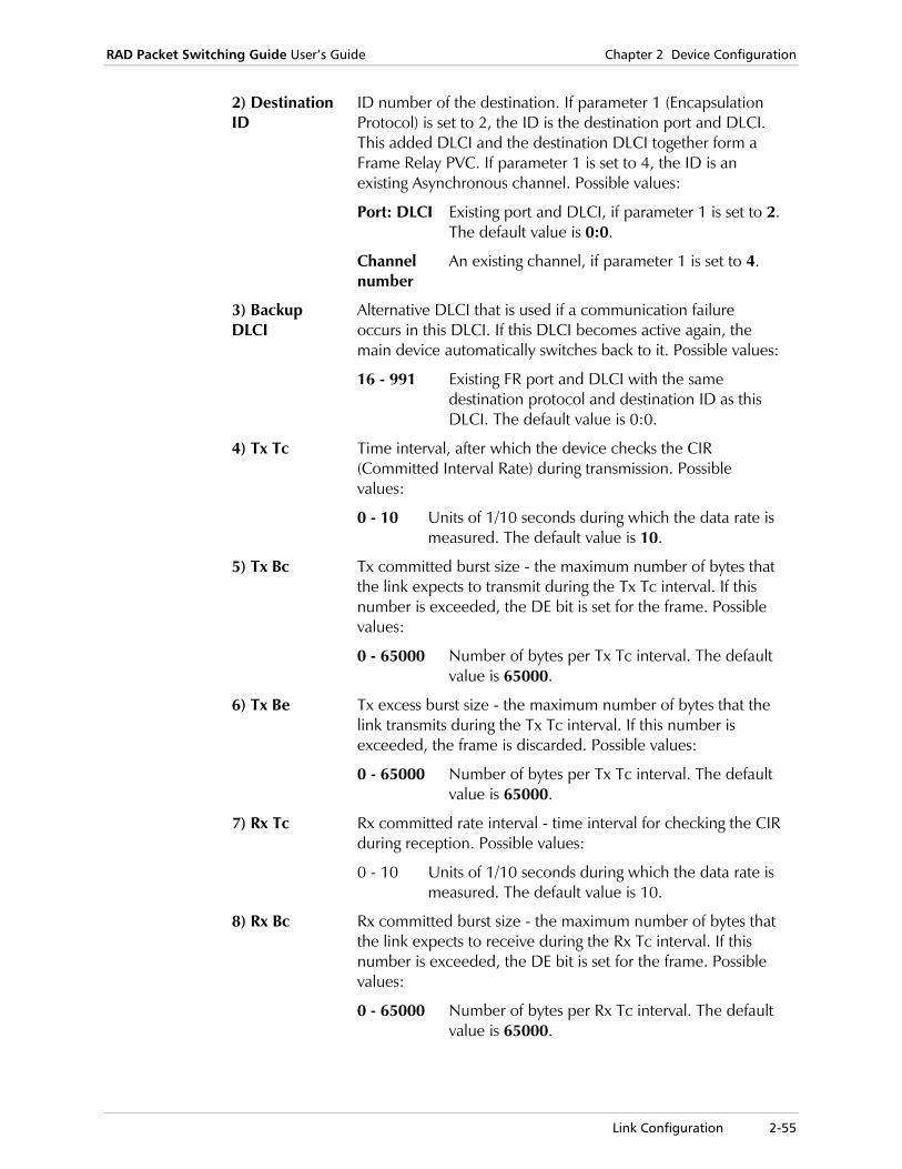
RAD Packet Switching Guide User’s Guide Chapter 2 Device Configuration
Link Configuration 2-55
2) Destination ID
ID number of the destination. If parameter 1 (Encapsulation Protocol) is set to 2, the ID is the destination port and DLCI. This added DLCI and the destination DLCI together form a Frame Relay PVC. If parameter 1 is set to 4, the ID is an existing Asynchronous channel. Possible values:
Port: DLCI Existing port and DLCI, if parameter 1 is set to 2. The default value is 0:0.
Channel number
An existing channel, if parameter 1 is set to 4.
3) Backup DLCI
Alternative DLCI that is used if a communication failure occurs in this DLCI. If this DLCI becomes active again, the main device automatically switches back to it. Possible values:
16 - 991 Existing FR port and DLCI with the same destination protocol and destination ID as this DLCI. The default value is 0:0.
4) Tx Tc Time interval, after which the device checks the CIR (Committed Interval Rate) during transmission. Possible values:
0 - 10 Units of 1/10 seconds during which the data rate is measured. The default value is 10.
5) Tx Bc Tx committed burst size - the maximum number of bytes that the link expects to transmit during the Tx Tc interval. If this number is exceeded, the DE bit is set for the frame. Possible values:
0 - 65000 Number of bytes per Tx Tc interval. The default value is 65000.
6) Tx Be Tx excess burst size - the maximum number of bytes that the link transmits during the Tx Tc interval. If this number is exceeded, the frame is discarded. Possible values:
0 - 65000 Number of bytes per Tx Tc interval. The default value is 65000.
7) Rx Tc Rx committed rate interval - time interval for checking the CIR during reception. Possible values:
0 - 10 Units of 1/10 seconds during which the data rate is measured. The default value is 10.
8) Rx Bc Rx committed burst size - the maximum number of bytes that the link expects to receive during the Rx Tc interval. If this number is exceeded, the DE bit is set for the frame. Possible values:
0 - 65000 Number of bytes per Rx Tc interval. The default value is 65000.

Chapter 2 Device Configuration RAD Packet Switching Guide User’s Guide
2-56 Link Configuration
9) Rx Be Rx excess burst size - the maximum number of bytes that the link receives during the Rx Tc interval. If this number is exceeded, the frame is discarded. Possible values:
0 - 65000 Number of bytes per Rx Tc interval. The default value is 65000.
10) Funnel ID Funnel ID that is attached to this DLCI (see Funnel Configuration on page 2-136). Possible values:
1 - 200 An existing funnel number for this device.
11) Tx Priority Transmission priority for this DLCI. Possible values:
0 - 3 0 indicates lowest priority, 3 indicates highest priority. The default value is 0.
12) ISDN Destination
Routing ID that is attached to this DLCI (see ISDN on page 2-180). Possible values:
1 - 200 An existing ISDN routing entry for this device.
Use the Update X.25 Parameters function to display and change the X.25 parameters of an X.25 encapsulated Frame Relay link. This operation is available only for a DLCI with Encapsulation Protocol parameter (parameter 1) is X.25.
To update X.25 parameters on a Frame Relay link:
1. In the Frame Relay Link n Configuration menu, select 4 (Update DLCI Parameters) and press <Enter>.
The DLCI xx Link n menu appears.
2. Select 2 (Update X.25 Configuration) and press <Enter>. If applicable, the X.25 Link n Configuration screen appears.
3. Change X.25 parameter values as required. For more information about the X.25 parameters, see X.25 Link Parameters on page 2-35.
4. To exit the X.25 Link n Configuration screen and return to the DLCI xx Link n menu, press <Enter> without making any parameter selection.
After the new parameter values are saved, the device continues to operate in accordance with the previous parameters values. The new parameters values will take effect the next time the device is reset or turned on!!!
Note
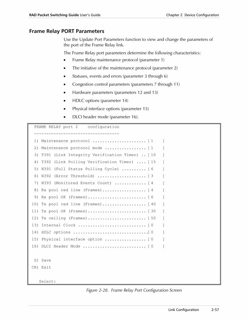
RAD Packet Switching Guide User’s Guide Chapter 2 Device Configuration
Link Configuration 2-57
Frame Relay PORT Parameters Use the Update Port Parameters function to view and change the parameters of the port of the Frame Relay link.
The Frame Relay port parameters determine the following characteristics:
• Frame Relay maintenance protocol (parameter 1)
• The initiative of the maintenance protocol (parameter 2)
• Statuses, events and errors (parameter 3 through 6)
• Congestion control parameters (parameters 7 through 11)
• Hardware parameters (parameters 12 and 13)
• HDLC options (parameter 14)
• Physical interface options (parameter 15)
• DLCI header mode (parameter 16).
FRAME RELAY port 2 configuration
-----------------------------------
1) Maintenance protocol ...................... [1 ]
2) Maintenance protocol mode ................. [1 ]
3) T391 (Link Integrity Verification Timer) .. [10 ]
4) T392 (Link Polling Verification Timer) .... [15 ]
5) N391 (Full Status Polling Cycle) .......... [6 ]
6) N392 (Error Threshold) .................... [3 ]
7) N393 (Monitored Events Count) ............. [4 ]
8) Rx pool red line (Frames).................. [4 ]
9) Rx pool OK (Frames)........................ [6 ]
10) Tx pool red line (Frames).................. [40 ]
11) Tx pool OK (Frames)........................ [30 ]
12) Tx ceiling (Frames)........................ [50 ]
13) Internal Clock ............................ [0 ]
14) HDLC options ...............................[0 ]
15) Physical interface option ................. [0 ]
16) DLCI Header Mode .......................... [0 ]
S) Save
CR) Exit
Select:
Figure 2-28. Frame Relay Port Configuration Screen
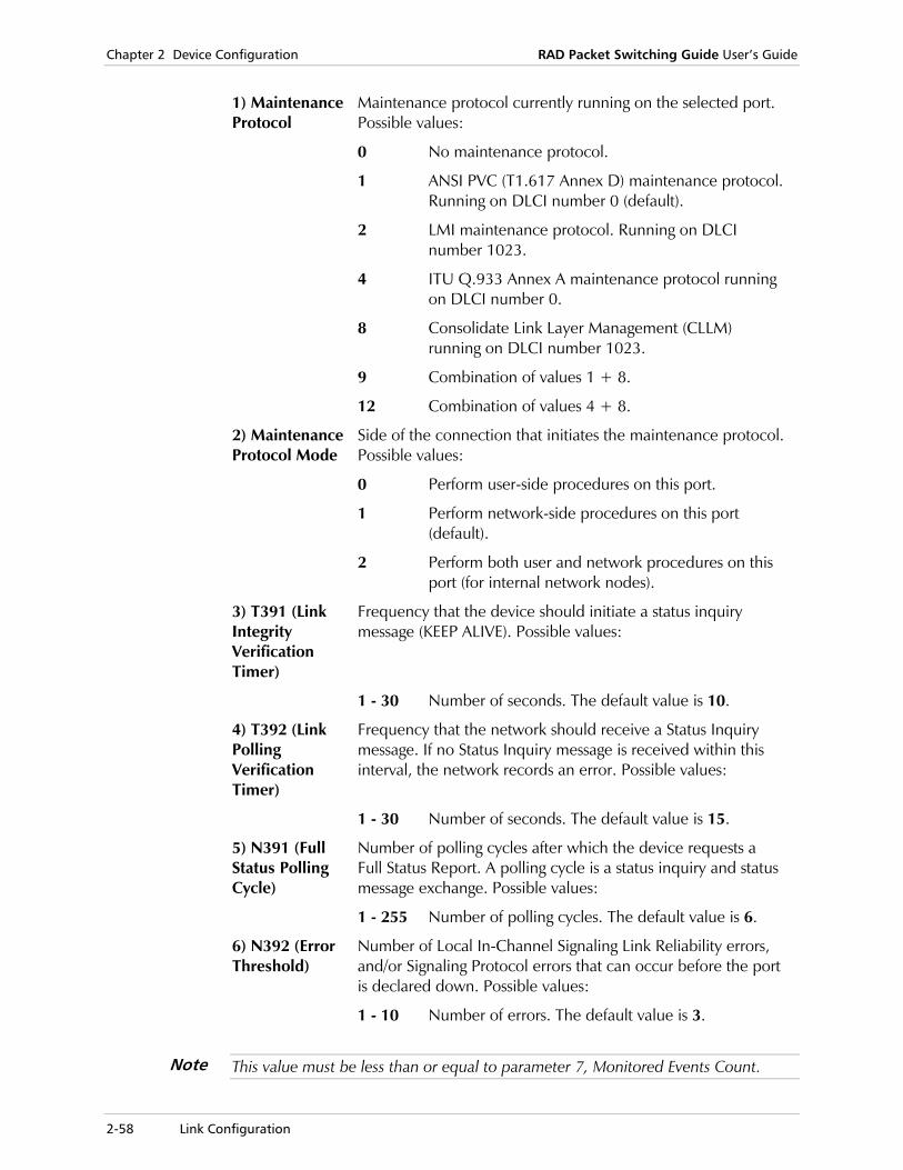
Chapter 2 Device Configuration RAD Packet Switching Guide User’s Guide
2-58 Link Configuration
1) Maintenance Protocol
Maintenance protocol currently running on the selected port. Possible values:
0 No maintenance protocol.
1 ANSI PVC (T1.617 Annex D) maintenance protocol. Running on DLCI number 0 (default).
2 LMI maintenance protocol. Running on DLCI number 1023.
4 ITU Q.933 Annex A maintenance protocol running on DLCI number 0.
8 Consolidate Link Layer Management (CLLM) running on DLCI number 1023.
9 Combination of values 1 + 8.
12 Combination of values 4 + 8.
2) Maintenance Protocol Mode
Side of the connection that initiates the maintenance protocol. Possible values:
0 Perform user-side procedures on this port.
1 Perform network-side procedures on this port (default).
2 Perform both user and network procedures on this port (for internal network nodes).
3) T391 (Link Integrity Verification Timer)
Frequency that the device should initiate a status inquiry message (KEEP ALIVE). Possible values:
1 - 30 Number of seconds. The default value is 10.
4) T392 (Link Polling Verification Timer)
Frequency that the network should receive a Status Inquiry message. If no Status Inquiry message is received within this interval, the network records an error. Possible values:
1 - 30 Number of seconds. The default value is 15.
5) N391 (Full Status Polling Cycle)
Number of polling cycles after which the device requests a Full Status Report. A polling cycle is a status inquiry and status message exchange. Possible values:
1 - 255 Number of polling cycles. The default value is 6.
6) N392 (Error Threshold)
Number of Local In-Channel Signaling Link Reliability errors, and/or Signaling Protocol errors that can occur before the port is declared down. Possible values:
1 - 10 Number of errors. The default value is 3.
This value must be less than or equal to parameter 7, Monitored Events Count.
Note
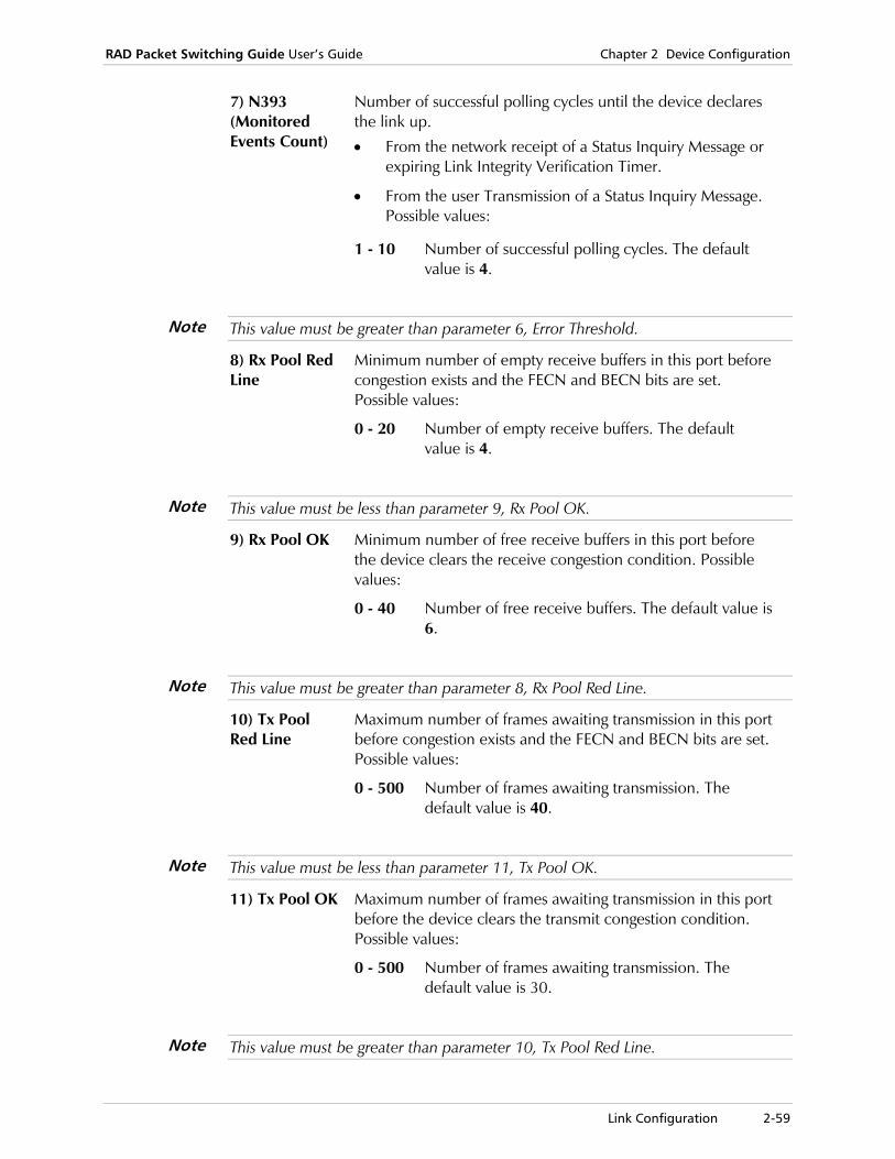
RAD Packet Switching Guide User’s Guide Chapter 2 Device Configuration
Link Configuration 2-59
7) N393 (Monitored Events Count)
Number of successful polling cycles until the device declares the link up.
• From the network receipt of a Status Inquiry Message or expiring Link Integrity Verification Timer.
• From the user Transmission of a Status Inquiry Message. Possible values:
1 - 10 Number of successful polling cycles. The default value is 4.
This value must be greater than parameter 6, Error Threshold.
8) Rx Pool Red Line
Minimum number of empty receive buffers in this port before congestion exists and the FECN and BECN bits are set. Possible values:
0 - 20 Number of empty receive buffers. The default value is 4.
This value must be less than parameter 9, Rx Pool OK.
9) Rx Pool OK Minimum number of free receive buffers in this port before the device clears the receive congestion condition. Possible values:
0 - 40 Number of free receive buffers. The default value is 6.
This value must be greater than parameter 8, Rx Pool Red Line.
10) Tx Pool Red Line
Maximum number of frames awaiting transmission in this port before congestion exists and the FECN and BECN bits are set. Possible values:
0 - 500 Number of frames awaiting transmission. The default value is 40.
This value must be less than parameter 11, Tx Pool OK.
11) Tx Pool OK Maximum number of frames awaiting transmission in this port before the device clears the transmit congestion condition. Possible values:
0 - 500 Number of frames awaiting transmission. The default value is 30.
This value must be greater than parameter 10, Tx Pool Red Line.
Note
Note
Note
Note
Note

Chapter 2 Device Configuration RAD Packet Switching Guide User’s Guide
2-60 Link Configuration
12) Tx Ceiling Maximum number of frames awaiting transmission allowed in this port. If linking a new frame for transmission will result in exceeding this number, the frame is discarded. Possible values:
0 - 500 Number of frames awaiting transmission. The default value is 50.
13) Internal Clock
Baud rate of the internal clock. Possible values:
0 External clock (default).
1 2.4 kbps.
2 4.8 kbps.
3 9.6 kbps.
4 14.4 kbps.
5 19.2 kbps.
6 38.4 kbps.
7 48 kbps.
8 56 kbps.
9 64 kbps.
10 128 kbps.
11 256 kbps.
12 384 kbps.
13 512 kbps.
14 768 kbps.
15 1008 kbps.
16 1466 kbps.
17 2016 kbps.
• At X.25 encapsulated protocol, this parameter overrides the X.25 Internal clock parameter
• For external clock, the interface is DTE, and for internal clock, the interface is DCE.
Notes
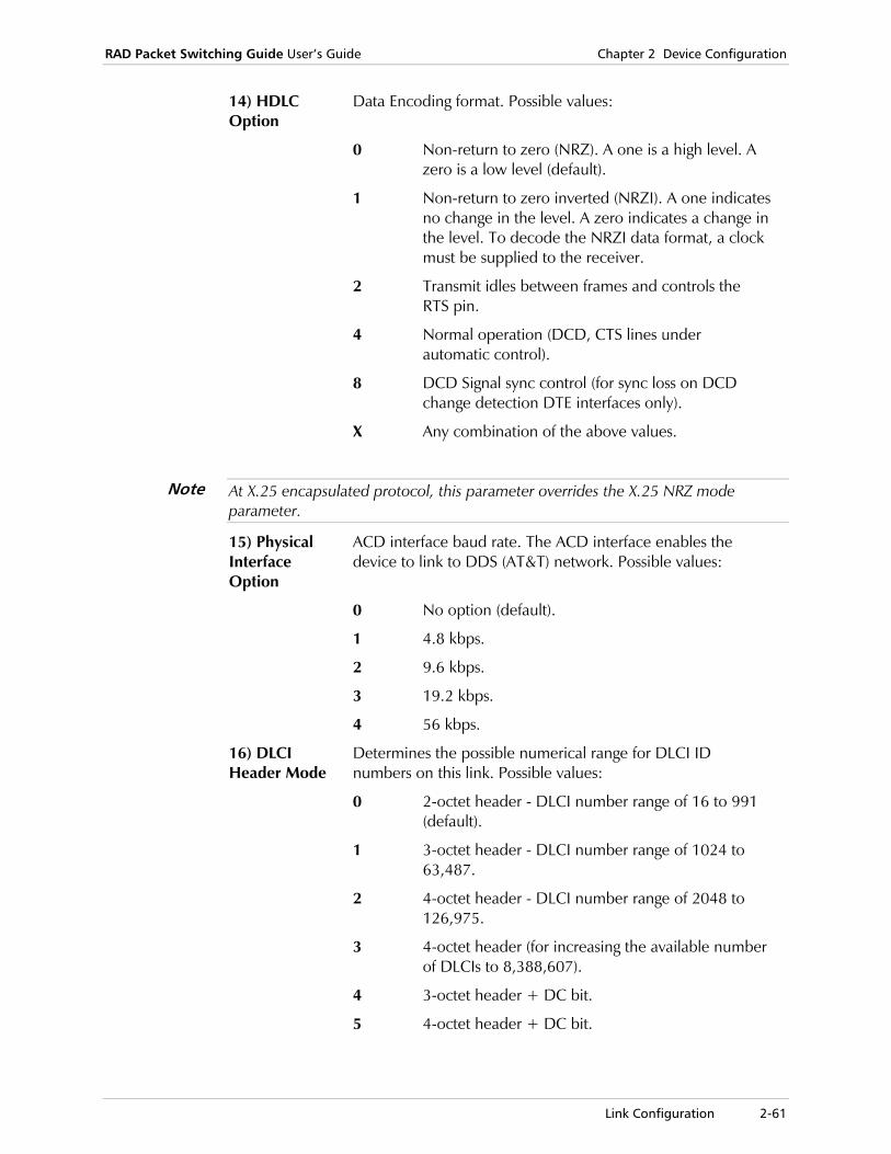
RAD Packet Switching Guide User’s Guide Chapter 2 Device Configuration
Link Configuration 2-61
14) HDLC Option
Data Encoding format. Possible values:
0 Non-return to zero (NRZ). A one is a high level. A zero is a low level (default).
1 Non-return to zero inverted (NRZI). A one indicates no change in the level. A zero indicates a change in the level. To decode the NRZI data format, a clock must be supplied to the receiver.
2 Transmit idles between frames and controls the RTS pin.
4 Normal operation (DCD, CTS lines under automatic control).
8 DCD Signal sync control (for sync loss on DCD change detection DTE interfaces only).
X Any combination of the above values.
At X.25 encapsulated protocol, this parameter overrides the X.25 NRZ mode parameter.
15) Physical Interface Option
ACD interface baud rate. The ACD interface enables the device to link to DDS (AT&T) network. Possible values:
0 No option (default).
1 4.8 kbps.
2 9.6 kbps.
3 19.2 kbps.
4 56 kbps.
16) DLCI Header Mode
Determines the possible numerical range for DLCI ID numbers on this link. Possible values:
0 2-octet header - DLCI number range of 16 to 991 (default).
1 3-octet header - DLCI number range of 1024 to 63,487.
2 4-octet header - DLCI number range of 2048 to 126,975.
3 4-octet header (for increasing the available number of DLCIs to 8,388,607).
4 3-octet header + DC bit.
5 4-octet header + DC bit.
Note
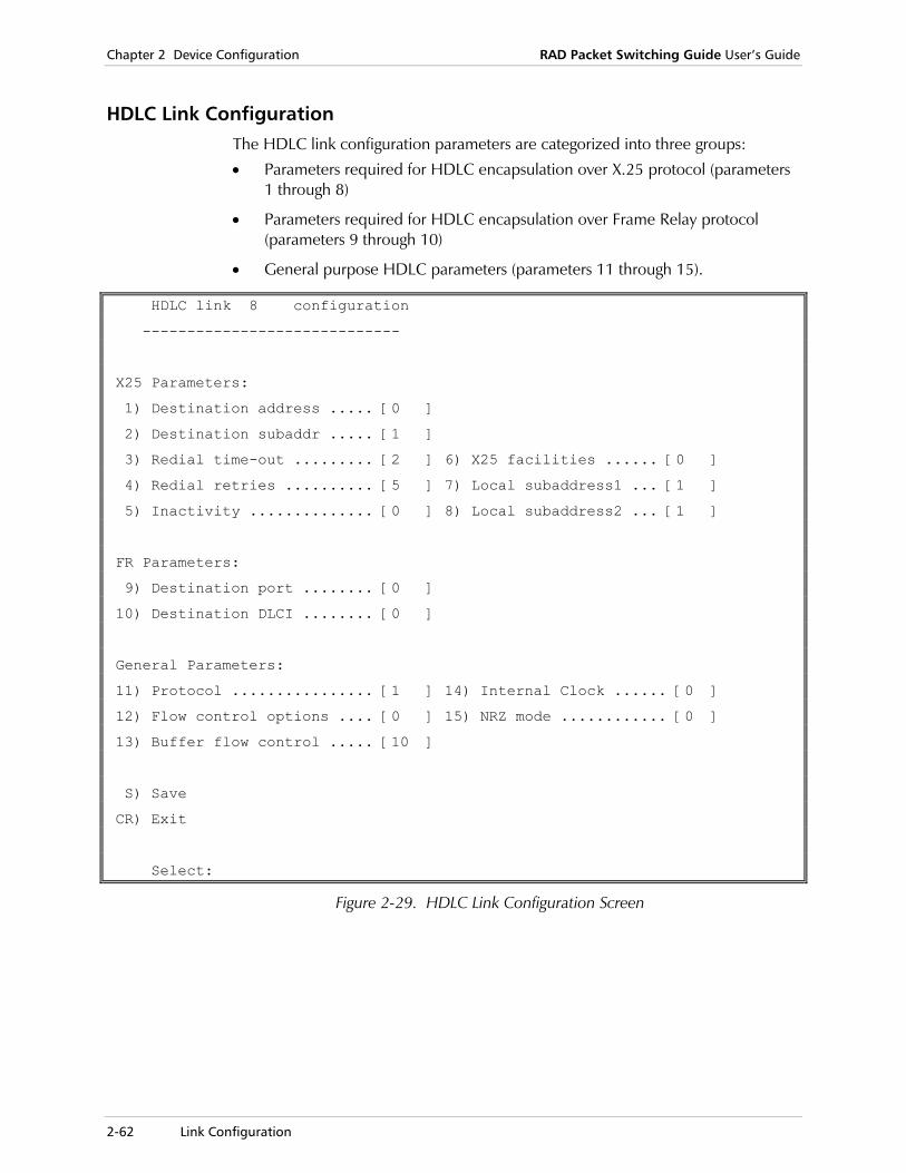
Chapter 2 Device Configuration RAD Packet Switching Guide User’s Guide
2-62 Link Configuration
HDLC Link Configuration The HDLC link configuration parameters are categorized into three groups:
• Parameters required for HDLC encapsulation over X.25 protocol (parameters 1 through 8)
• Parameters required for HDLC encapsulation over Frame Relay protocol (parameters 9 through 10)
• General purpose HDLC parameters (parameters 11 through 15).
HDLC link 8 configuration
-----------------------------
X25 Parameters:
1) Destination address ..... [0 ]
2) Destination subaddr ..... [1 ]
3) Redial time-out ......... [2 ] 6) X25 facilities ...... [0 ]
4) Redial retries .......... [5 ] 7) Local subaddress1 ... [1 ]
5) Inactivity .............. [0 ] 8) Local subaddress2 ... [1 ]
FR Parameters:
9) Destination port ........ [0 ]
10) Destination DLCI ........ [0 ]
General Parameters:
11) Protocol ................ [1 ] 14) Internal Clock ...... [0 ]
12) Flow control options .... [0 ] 15) NRZ mode ............ [0 ]
13) Buffer flow control ..... [10 ]
S) Save
CR) Exit
Select:
Figure 2-29. HDLC Link Configuration Screen

RAD Packet Switching Guide User’s Guide Chapter 2 Device Configuration
Link Configuration 2-63
1) Destination Address
X.25 address of the remote device. Possible values:
Up to 15 digits X.25 address. The default value is 0.
2) Destination Subaddress
Synchronous link subaddress on the remote device. The HDLC link is remotely routed to this subaddress. Possible values:
2-digit number Synchronous link subaddress. The default value is 1.
3) Redial Timeout
Time interval between two consecutive connection retries. Possible values:
0 - 255 Time interval in seconds. The default value is 2.
4) Redial Retries
Number of times the device repeats the call operation if the call request failed. Possible values:
0 Retry operation is disabled.
1 - 255 Number of retries. The default value is 5.
5)Inactivity Amount of time of inactivity after which the session disconnects. Possible values:
0 No disconnection after inactivity.
1 - 255 Number of minutes. The default value is 0.
6) X.25 Facilities
X.25 facilities available to the link if HDLC is encapsulated over X.25.Possible values:
0 No options (default).
1 Packet size negotiation.
2 Window size negotiation.
4 Reverse charge.
X Any combination of the above values.
7) Local Subaddress1
Local synchronous link subaddress number 1. Possible values:
2-digit number Synchronous link subaddress. The default value is 1.
8) Local Subaddress2
Local synchronous link subaddress number 2.Possible values:
2-digit number Synchronous link subaddress. The default value is 1.
9) Destination Port
Local port, which is used for HDLC encapsulation over Frame Relay. Possible values: Any valid link number. The default value is 0.
The device accepts ports previously configured as Frame Relay links only.
Note
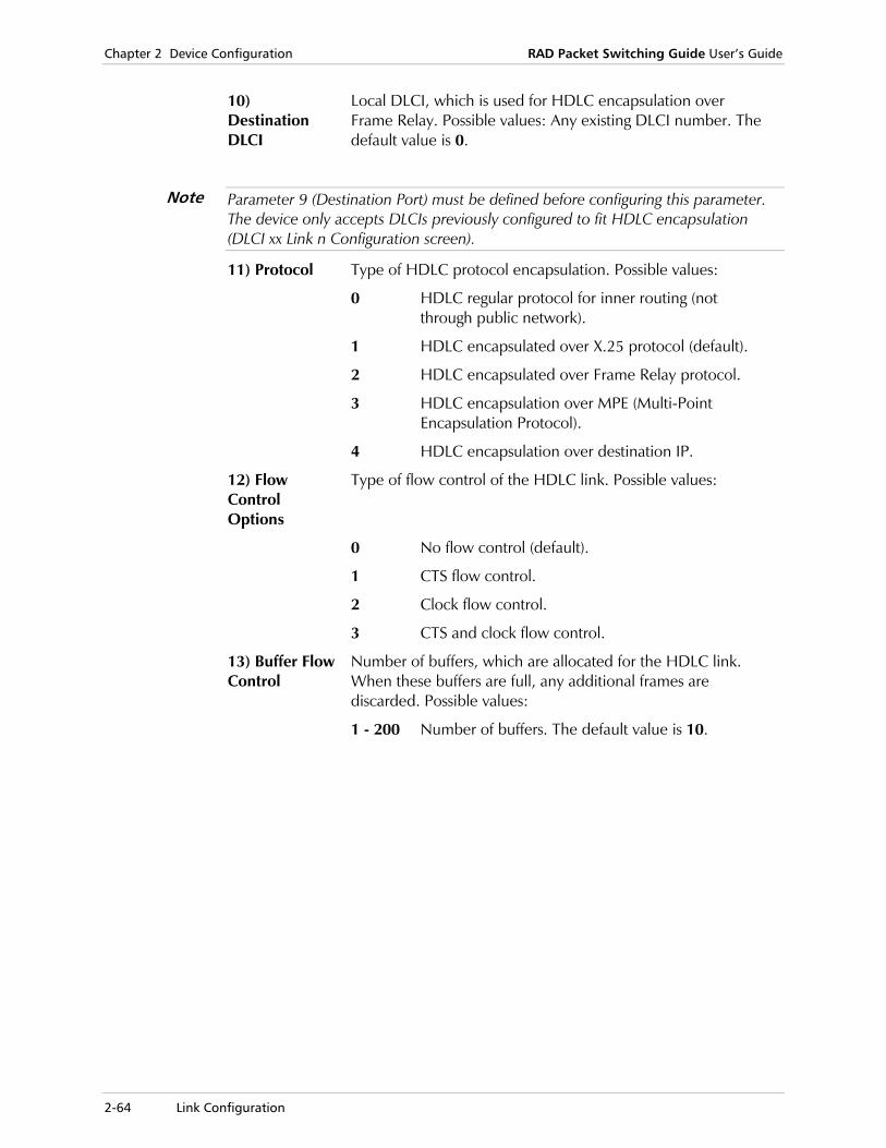
Chapter 2 Device Configuration RAD Packet Switching Guide User’s Guide
2-64 Link Configuration
10) Destination DLCI
Local DLCI, which is used for HDLC encapsulation over Frame Relay. Possible values: Any existing DLCI number. The default value is 0.
Parameter 9 (Destination Port) must be defined before configuring this parameter. The device only accepts DLCIs previously configured to fit HDLC encapsulation (DLCI xx Link n Configuration screen).
11) Protocol Type of HDLC protocol encapsulation. Possible values:
0 HDLC regular protocol for inner routing (not through public network).
1 HDLC encapsulated over X.25 protocol (default).
2 HDLC encapsulated over Frame Relay protocol.
3 HDLC encapsulation over MPE (Multi-Point Encapsulation Protocol).
4 HDLC encapsulation over destination IP.
12) Flow Control Options
Type of flow control of the HDLC link. Possible values:
0 No flow control (default).
1 CTS flow control.
2 Clock flow control.
3 CTS and clock flow control.
13) Buffer Flow Control
Number of buffers, which are allocated for the HDLC link. When these buffers are full, any additional frames are discarded. Possible values:
1 - 200 Number of buffers. The default value is 10.
Note
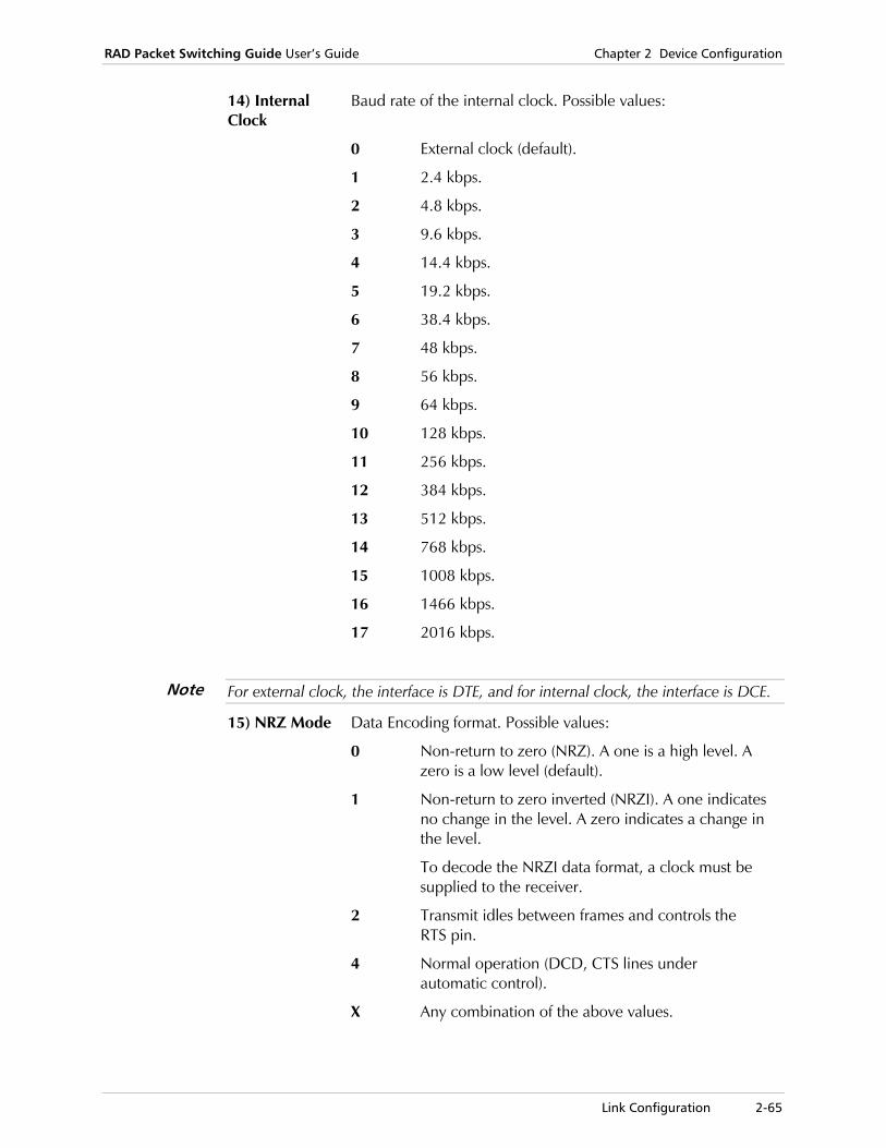
RAD Packet Switching Guide User’s Guide Chapter 2 Device Configuration
Link Configuration 2-65
14) Internal Clock
Baud rate of the internal clock. Possible values:
0 External clock (default).
1 2.4 kbps.
2 4.8 kbps.
3 9.6 kbps.
4 14.4 kbps.
5 19.2 kbps.
6 38.4 kbps.
7 48 kbps.
8 56 kbps.
9 64 kbps.
10 128 kbps.
11 256 kbps.
12 384 kbps.
13 512 kbps.
14 768 kbps.
15 1008 kbps.
16 1466 kbps.
17 2016 kbps.
For external clock, the interface is DTE, and for internal clock, the interface is DCE.
15) NRZ Mode Data Encoding format. Possible values:
0 Non-return to zero (NRZ). A one is a high level. A zero is a low level (default).
1 Non-return to zero inverted (NRZI). A one indicates no change in the level. A zero indicates a change in the level.
To decode the NRZI data format, a clock must be supplied to the receiver.
2 Transmit idles between frames and controls the RTS pin.
4 Normal operation (DCD, CTS lines under automatic control).
X Any combination of the above values.
Note

Chapter 2 Device Configuration RAD Packet Switching Guide User’s Guide
2-66 Link Configuration
SDLC Parameters For SDLC PAD links, the SDLC Line n Configuration screen contains the configuration parameters.
SDLC Line 1 configuration
-----------------------------------
1) SDLC Link Type ............................ [1 ]
2) Link Participates with More Than One PU ... [1 ]
3) Duplex Physical Level ..................... [0 ]
4) Number of Flags Between Frames ............ [2 ]
5) Duplex Link Level ......................... [0 ]
6) Clock ..................................... [0 ]
7) Physical Mode ............................. [0 ]
S) Save
CR) Exit
Select:
Figure 2-30. SDLC Line Configuration Screen
1) SDLC Link Type
Defines whether the SDLC is primary or secondary. Possible values:
0 Secondary SDLC.
1 Primary SDLC (default).
2) Link Participates with More Than One PU
Presence of at least one PU on the SDLC link. Possible values:
0 NO. This value is used when only a single PU/F_EP is connected to the device.
1 YES. This value indicates one of the following:
• More than one PU has been added on the line. (i.e. defined in the SDLC PU configuration menu).
• The RAD device line is physically co-existing with other hardware devices, on a multi-point link.
3) Duplex Physical Level
Defines whether the Physical Level of the SDLC line is Half or Full Duplex. Possible values:
0 Half Duplex (default).
1 Full Duplex.

RAD Packet Switching Guide User’s Guide Chapter 2 Device Configuration
Link Configuration 2-67
4) Number of Flags Between Frames
Defines the number of flags between frames. Possible values: 1 - 15. The default value is 2.
5) Duplex Link Level
Indicates whether the link level is Two Way Alternate or Two Way Simultaneous. Possible values:
0 Two Way Alternate (default).
1 Two Way Simultaneous.
6) Clock Baud rate of the internal clock. Possible values:
0 External clock (default).
1 2.4 kbps.
2 4.8 kbps.
3 9.6 kbps.
4 14.4 kbps.
5 19.2 kbps.
6 38.4 kbps.
7 48 kbps.
8 56 kbps.
9 64 kbps.
10 128 kbps.
11 256 kbps.
12 384 kbps.
13 512 kbps.
14 768 kbps.
15 1008 kbps.
16 1466 kbps.
17 2016 kbps.
7) Physical Mode
Non-return-to-zero (NRZ) mode. This parameter defines if the NRZ signal is regular NRZ or NRZI. Possible values:
0 NRZ with FLAGs between frames. RTS is constant (default).
1 NRZI with FLAGs between frames. RTS is constant.
2 NRZ with IDLE between frames. RTS is controlled.
4 NRZI with IDLE between frames. RTS is controlled.
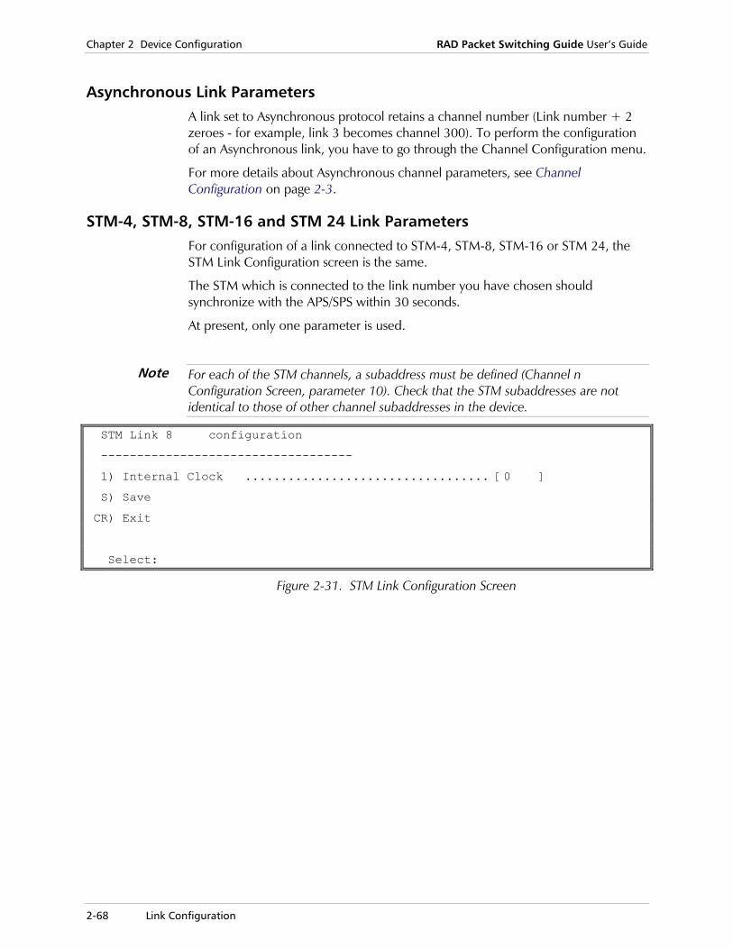
Chapter 2 Device Configuration RAD Packet Switching Guide User’s Guide
2-68 Link Configuration
Asynchronous Link Parameters A link set to Asynchronous protocol retains a channel number (Link number + 2 zeroes - for example, link 3 becomes channel 300). To perform the configuration of an Asynchronous link, you have to go through the Channel Configuration menu.
For more details about Asynchronous channel parameters, see Channel Configuration on page 2-3.
STM-4, STM-8, STM-16 and STM 24 Link Parameters For configuration of a link connected to STM-4, STM-8, STM-16 or STM 24, the STM Link Configuration screen is the same.
The STM which is connected to the link number you have chosen should synchronize with the APS/SPS within 30 seconds.
At present, only one parameter is used.
For each of the STM channels, a subaddress must be defined (Channel n Configuration Screen, parameter 10). Check that the STM subaddresses are not identical to those of other channel subaddresses in the device.
STM Link 8 configuration
-----------------------------------
1) Internal Clock .................................. [0 ]
S) Save
CR) Exit
Select:
Figure 2-31. STM Link Configuration Screen
Note
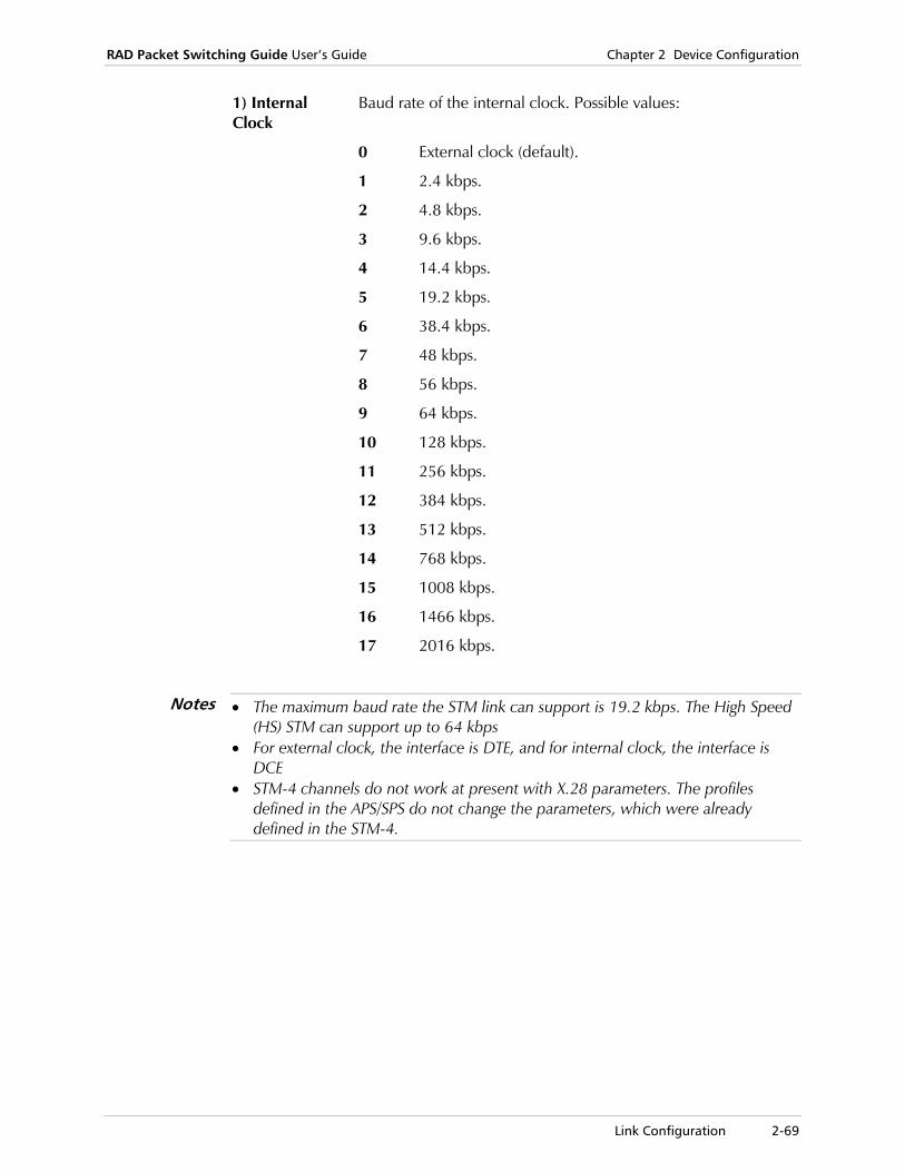
RAD Packet Switching Guide User’s Guide Chapter 2 Device Configuration
Link Configuration 2-69
1) Internal Clock
Baud rate of the internal clock. Possible values:
0 External clock (default).
1 2.4 kbps.
2 4.8 kbps.
3 9.6 kbps.
4 14.4 kbps.
5 19.2 kbps.
6 38.4 kbps.
7 48 kbps.
8 56 kbps.
9 64 kbps.
10 128 kbps.
11 256 kbps.
12 384 kbps.
13 512 kbps.
14 768 kbps.
15 1008 kbps.
16 1466 kbps.
17 2016 kbps.
• The maximum baud rate the STM link can support is 19.2 kbps. The High Speed (HS) STM can support up to 64 kbps
• For external clock, the interface is DTE, and for internal clock, the interface is DCE
• STM-4 channels do not work at present with X.28 parameters. The profiles defined in the APS/SPS do not change the parameters, which were already defined in the STM-4.
Notes

Chapter 2 Device Configuration RAD Packet Switching Guide User’s Guide
2-70 Link Configuration
MPE Link Parameters The Multi Point Encapsulation (MPE) is a proprietary RAD protocol. It is used to enable a generic HDLC device, or for multiple encapsulation of data packets over X.25, Frame Relay or HDLC protocols.
Using MPE protocol requires the configuration of two main sets of parameters:
• Port - Specifies the attributes related directly to the MPE link.
• AID (Address ID) - . AID identifies the logical link across the physical port and the session onto which the data is forwarded.
Selecting an MPE link enables the following configuration activities:
• Adding a new AID
• Updating an existing AID parameter
• Updating port parameters
• Deleting an AID
This section also contains descriptions of parameters for AIDs and MPE ports.
For a description of the MPE protocol, see Chapter 7, Protocols.
To use the Multi Point Encapsulator Link (MPE) n Configuration menu:
1. In the Link Configuration menu, select 3 (Update Link Parameters) and press <Enter>.
A list of links and their corresponding protocol types appears.
2. Type the number of the MPE link you want and press <Enter>. The Multi Point Encapsulator Link (MPE) n Configuration menu appears.
Multi Point Encapsulator Link (MPE) 8 configuration
---------------------------------------------------------
1) Add AID.
2) Delete AID.
3) Update PORT parameters.
4) Update AID parameters.
CR) Exit
Select:
Figure 2-32. MPE Link n Configuration Menu
3. Type the number of a function and press <Enter>. The appropriate menu appears.
4. To return to the list of links, press <Enter> without selecting an option.

RAD Packet Switching Guide User’s Guide Chapter 2 Device Configuration
Link Configuration 2-71
Adding an AID
An AID (Address ID) is a unique identifier for a network connection of a logical link through a physical port. Use the Add AID function to define a new AID and select the values for its parameters.
New AIDs can only be defined for an MPE link that was previously selected.
To add an AID:
1. In the Multi Point Encapsulator Link (MPE) n Configuration menu, select 1 (Add AID) and press <Enter>.
A list of existing AIDs appears.
2. Type a number for the new AID (1 - 251) and press <Enter>. The AID x Link n Configuration screen appears. The AID number (x) and link number (n) are identified in the screen title. When you configure an AID for the first time, this screen displays the default values. For more details, see AID Parameters on page 2-73.
3. To configure a specific parameter, type its number and press <Enter>. The device prompts you for the new parameter value.
4. Type a new parameter value and press <Enter>. The new value appears in the value column.
5. Type S and press <Enter> to save the new configuration.
To cancel the changes you made, exit without saving the new values.
6. To exit the AID x Link n Configuration screen, press <Enter> without making any parameter selection.
Updating AID Parameters
Use the Update AID Parameters function to change the parameter values for a new or existing AID.
To update an AID:
1. In the Multi Point Encapsulator Link (MPE) n Configuration menu, select 4 (Update AID Parameters).
A list of existing AIDs appears.
2. Type the number of the AID (1 - 251) you want to update and press <Enter>.
The AID x Link n Configuration screen appears. The AID number (x) and link number (n) are identified in the screen title.
3. Repeat steps 3 - 6 of the procedure in Adding an AID on page 2-71.
Note
Note
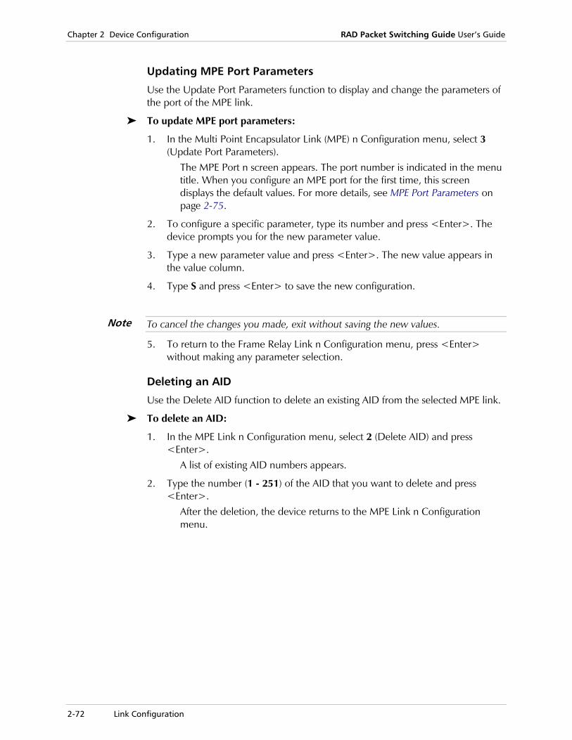
Chapter 2 Device Configuration RAD Packet Switching Guide User’s Guide
2-72 Link Configuration
Updating MPE Port Parameters
Use the Update Port Parameters function to display and change the parameters of the port of the MPE link.
To update MPE port parameters:
1. In the Multi Point Encapsulator Link (MPE) n Configuration menu, select 3 (Update Port Parameters).
The MPE Port n screen appears. The port number is indicated in the menu title. When you configure an MPE port for the first time, this screen displays the default values. For more details, see MPE Port Parameters on page 2-75.
2. To configure a specific parameter, type its number and press <Enter>. The device prompts you for the new parameter value.
3. Type a new parameter value and press <Enter>. The new value appears in the value column.
4. Type S and press <Enter> to save the new configuration.
To cancel the changes you made, exit without saving the new values.
5. To return to the Frame Relay Link n Configuration menu, press <Enter> without making any parameter selection.
Deleting an AID
Use the Delete AID function to delete an existing AID from the selected MPE link.
To delete an AID:
1. In the MPE Link n Configuration menu, select 2 (Delete AID) and press <Enter>.
A list of existing AID numbers appears.
2. Type the number (1 - 251) of the AID that you want to delete and press <Enter>.
After the deletion, the device returns to the MPE Link n Configuration menu.
Note

RAD Packet Switching Guide User’s Guide Chapter 2 Device Configuration
Link Configuration 2-73
AID Parameters The AID Configuration parameters define main and secondary AIDs to the MPE data packets.
AID 1 Link 8 configuration ------------------------------------- 1) Main Type ......... [Not active] 2) Main ID ........... [Not Set] 3) Main Sub ID ....... [Not Set] 4) Backup Type ....... [Not active] 5) Backup ID ......... [Not Set] 6) Backup Sub ID ..... [Not Set] S) Save. CR) Exit. Select:
Figure 2-33. AID MPE Link Configuration Screen
1) Main Type Protocol of the link over which the MPE data is encapsulated. Possible values:
0 Not active (default).
1 X.25 SVC
2 X.25 PVC
3 Frame Relay PVC
4 Inner Communication
Chapter 2 Device Configuration RAD Packet Switching Guide User’s Guide
2-74 Link Configuration
2) Main ID ID of the destination port or link for the MPE-encapsulated (or not) packets. Possible values:
Call ID number
Pre-defined Call ID number (see Call ID Configuration on page 2-107). Applicable if parameter 1 is set to X.25 SVC.
The Call ID must be defined with a blank after the ‘C’. For example, “C 143.”
PVC entry Pre-defined PVC (see PVC Configuration on page 2-101). Applicable if parameter 1 is set to X.25 PVC.
Frame Relay Link Number
Frame Relay link number to which the encapsulated MPE packets are referred. Applicable if parameter 1 is set to Frame Relay PVC.
HDLC or MPE Link Number
HDLC or MPE link number to which the MPE packets are referred. Applicable if parameter 1 is set to Inner Communication.
3) Main Sub ID Local ID of the destination specified in parameter 2. The Sub ID parameter is applicable only when AID Type is defined as Frame Relay or Inner Communications. Possible values:
0 If the Main Type is X.25 or Not Active, this parameter is not relevant.
If the Main Type is Inner Communication, and the link is HDLC, this parameter must be 0.
AID number
Pre-defined AID. Applicable when the MPE packets are forwarded to another MPE link.
DLCI number (not 0 or 1023)
Pre-defined DLCI. Applicable when the MPE packets are forwarded to a Frame Relay link.
The DLCI’s destination protocol must be set to MPE (see DLCI Parameters on page 2-53).
For parameters 4 - 6, the same AID parameters are defined for a backup AID. The backup AID can be activated when the Main Type is defined as PVC. If the main AID connection falls, the device switches to the backup AID connection. After the main AID is reconnected, the connection will automatically transfer to the main AID.
Note
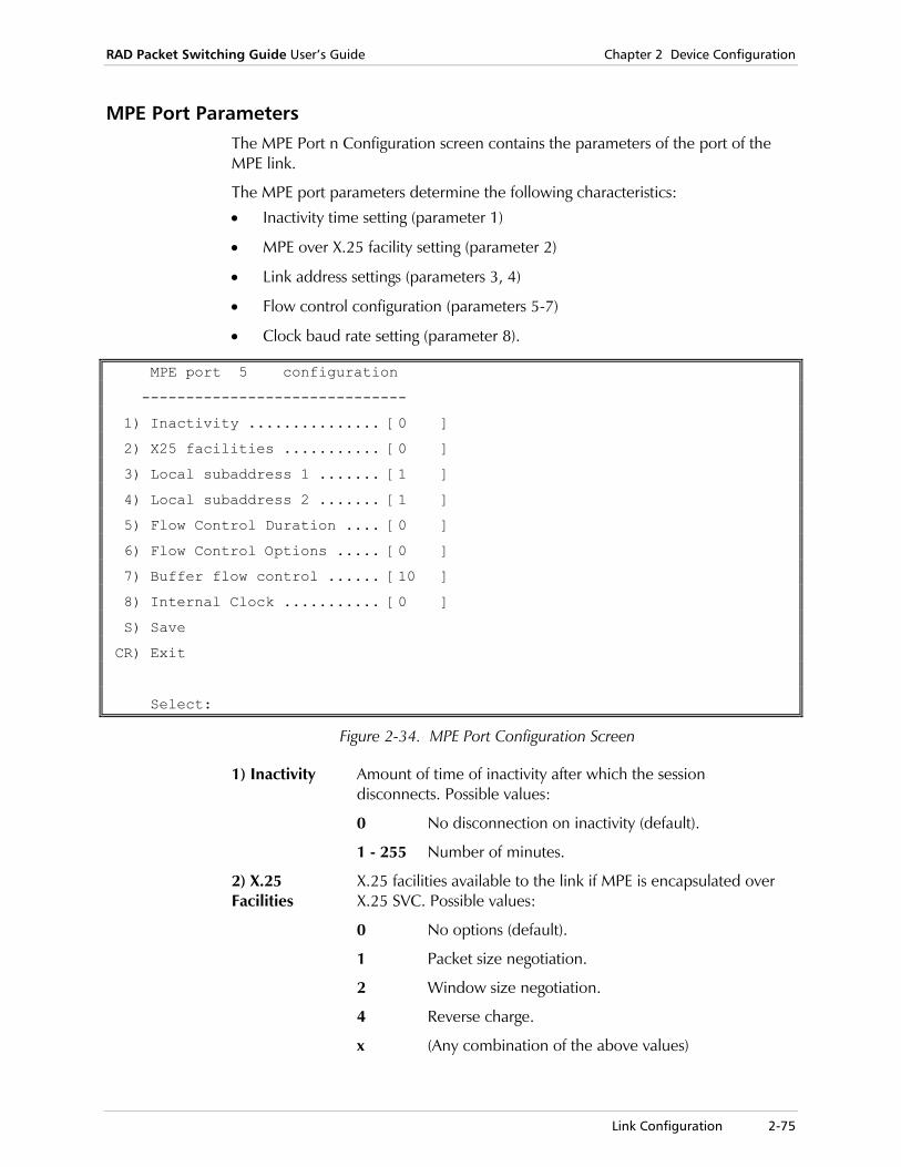
RAD Packet Switching Guide User’s Guide Chapter 2 Device Configuration
Link Configuration 2-75
MPE Port Parameters The MPE Port n Configuration screen contains the parameters of the port of the MPE link.
The MPE port parameters determine the following characteristics:
• Inactivity time setting (parameter 1)
• MPE over X.25 facility setting (parameter 2)
• Link address settings (parameters 3, 4)
• Flow control configuration (parameters 5-7)
• Clock baud rate setting (parameter 8).
MPE port 5 configuration
------------------------------
1) Inactivity ............... [0 ]
2) X25 facilities ........... [0 ]
3) Local subaddress 1 ....... [1 ]
4) Local subaddress 2 ....... [1 ]
5) Flow Control Duration .... [0 ]
6) Flow Control Options ..... [0 ]
7) Buffer flow control ...... [10 ]
8) Internal Clock ........... [0 ]
S) Save
CR) Exit
Select:
Figure 2-34. MPE Port Configuration Screen
1) Inactivity Amount of time of inactivity after which the session disconnects. Possible values:
0 No disconnection on inactivity (default).
1 - 255 Number of minutes.
2) X.25 Facilities
X.25 facilities available to the link if MPE is encapsulated over X.25 SVC. Possible values:
0 No options (default).
1 Packet size negotiation.
2 Window size negotiation.
4 Reverse charge.
x (Any combination of the above values)

Chapter 2 Device Configuration RAD Packet Switching Guide User’s Guide
2-76 Link Configuration
3) Local Subaddress 1
Primary local subaddress of a link connected to this MPE link. Applicable only when MPE is encapsulated over X.25 SVC. Possible values: A two-digit number. The default value is 1.
4) Local Subaddress 2
Secondary local subaddress of a link connected to this MPE link. Applicable only when MPE is encapsulated over X.25 SVC. Possible values: A two-digit number. The default value is 1.
5) Flow Control Duration
Maximum time interval of the hardware flow control signal to the transmitting device. Possible values:
0 No hardware flow control (default).
1 - 200 Units of 50 ms.
6) Flow Control Options
Type of flow control of the HDLC link. Possible values:
0 No flow control (default).
1 CTS flow control.
2 Clock flow control
3 CTS and clock flow control.
Flow control activation requires a flow control duration setting greater than 0 (parameter 5).
7) Buffer Flow Control
Number of buffers, which are allocated for each AID on the MPE link. When these buffers are full, any additional frames are discarded. Possible values:
1 - 255 Number of buffers. The default value is 10.
Note

RAD Packet Switching Guide User’s Guide Chapter 2 Device Configuration
Link Configuration 2-77
8)Internal Clock
Baud rate of the internal clock. Possible values:
0 External clock (default).
1 2.4 kbps.
2 4.8 kbps.
3 9.6 kbps.
4 14.4 kbps.
5 19.2 kbps.
6 38.4 kbps.
7 48 kbps.
8 56 kbps.
9 64 kbps.
10 128 kbps.
11 256 kbps.
12 384 kbps.
13 512 kbps.
14 768 kbps.
15 1008 kbps.
16 1466 kbps.
17 2016 kbps.
For external clock, the interface is DTE, and for internal clock, the interface is DCE.
Note

Chapter 2 Device Configuration RAD Packet Switching Guide User’s Guide
2-78 Link Configuration
Bisync Link Parameters The RAD SPS Bisync application enables the user to connect a Host computer to several terminals, where the Host and the terminals communicate with the RAD packet switching device using the Bisync protocol and the RAD devices are connected to an X.25 network. The conversion from Bisync to X.25 and vice versa is transparent both to the Host and to the terminals.
The device on the host side is called HPAD (Host Packet Assembly/Disassembly) and the devices on the terminals side are called TPAD (Terminal Packet Assembly/Disassembly). A Host can communicate with only one HPAD, whereas each TPAD can communicate with more than one terminal.
The Bisync application includes the following features:
• Local spoofing of all Bisync polls. Only data traverses the X.25 network
• Burroughs poll-select and IBM BSC-III
• Flexible configuration for various Bisync implementation.
This section describes the parameters for HPAD and TPAD devices.
The following figure shows an example of a Bisync application.
Host
SPS HPAD
SPS TPAD
SPS TPAD
BSCController
BSCController
BSCController
BSCController
BSCController
BSCController
BSC
BSC
BSC
BSC
BSC
X.25
Figure 2-35. RAD SPS Bisync Application Sample
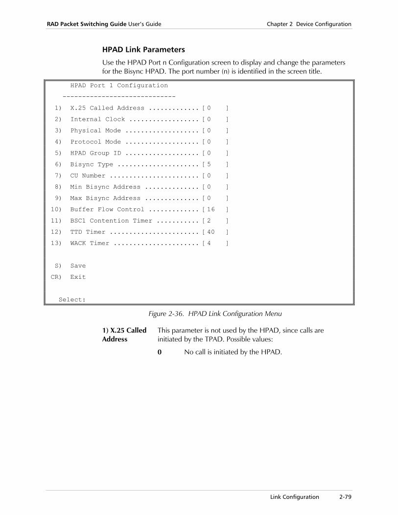
RAD Packet Switching Guide User’s Guide Chapter 2 Device Configuration
Link Configuration 2-79
HPAD Link Parameters
Use the HPAD Port n Configuration screen to display and change the parameters for the Bisync HPAD. The port number (n) is identified in the screen title.
HPAD Port 1 Configuration
-----------------------------
1) X.25 Called Address ............. [0 ]
2) Internal Clock .................. [0 ]
3) Physical Mode ................... [0 ]
4) Protocol Mode ................... [0 ]
5) HPAD Group ID ................... [0 ]
6) Bisync Type ..................... [5 ]
7) CU Number ....................... [0 ]
8) Min Bisync Address .............. [0 ]
9) Max Bisync Address .............. [0 ]
10) Buffer Flow Control ............. [16 ]
11) BSC1 Contention Timer ........... [2 ]
12) TTD Timer ....................... [40 ]
13) WACK Timer ...................... [4 ]
S) Save
CR) Exit
Select:
Figure 2-36. HPAD Link Configuration Menu
1) X.25 Called Address
This parameter is not used by the HPAD, since calls are initiated by the TPAD. Possible values:
0 No call is initiated by the HPAD.

Chapter 2 Device Configuration RAD Packet Switching Guide User’s Guide
2-80 Link Configuration
2) Internal Clock
Baud rate of the internal clock. Possible values:
0 External clock (default).
1 3 kbps.
2 4.8 kbps.
3 9.6 kbps.
4 14.4 kbps.
5 19.2 kbps.
6 38.4 kbps.
7 48 kbps.
8 56 kbps.
9 64 kbps.
10 128 kbps.
11 256 kbps.
12 384 kbps.
13 512 kbps.
14 768 kbps.
15 1024 kbps.
16 1445 kbps.
17 2048 kbps.
For external clock, the interface is DTE, and for internal clock, the interface is DCE.
3) Physical Mode
Physical mode of the link. Possible values:
1 Non-return to zero inverted (NRZI).
2 8-bit CRC (LRC).
3 Combination of the above modes.
4) Protocol Mode
Mode of packets acknowledgement. Possible values:
1 Acknowledge by RVI.
2 Send Temporary Transmission Delay (TTD) packet during transmission.
3 Combination of the above modes.
Only change this parameter if necessary.
Note
Note

RAD Packet Switching Guide User’s Guide Chapter 2 Device Configuration
Link Configuration 2-81
5) HPAD group ID
Destination HPAD group. The HPAD group ID in the remote TPAD must be set to this parameter. Possible values:
Any valid Bisync PAD number
The number of the destination HPAD group. The default value is 0.
6) Bisync Type Type of the Bisync link. Possible values:
1 Burroughs.
2 BS3 EBCDIC.
3 BS3 ASCII.
4 BS1 EBCDIC.
5 BS1 ASCII (default).
7) CU Number Number of the Control Unit attached to the HPAD. This parameter is used only with IBM Bisync. Possible values:
0 - 31 The number of the controller attached to the Control Unit. For example, for polling address C1, use controller 1. The default value is 0.
8) Min Bisync Address
Lowest remote terminal address from which the Host terminal scanning process begins. Possible values:
0 - 31 For IBM type.
0 - 99 For Burroughs type.
9) Max Bisync Address
Highest remote terminal address at which the Host terminal scanning process ends. Possible values:
0 - 31 For IBM type.
0 - 99 For Burroughs type.
10) Buffer Flow Control
Number of buffers to be allocated for the HDLC link. Possible values: Any number. The default value is 16.
11) BSC1 Contention Timer
Time interval between the reception of an ENQ inquiry packet on the BSC interface, and the response from the remote device. Until this interval expires, the SPS discards other ENQ inquiries in order to receive an acknowledgement (ACK) message from the remote device. This parameter is applicable for BSC1 only. Possible values:
1 - 255 A unit of 50 ms. The default value is 2.
12) TTD Timer Temporary Transmission Delay (TTD) timer. Maximum time that the SPS waits to receive data from the X.25 remote device, before sending a TTD packet to the local bisync device. Possible values:
1 - 255 A unit of 50 ms. The default value is 40.

Chapter 2 Device Configuration RAD Packet Switching Guide User’s Guide
2-82 Link Configuration
13) WACK Timer
Wait Acknowledgement (WACK) timer. Maximum time that the SPS waits to receive a response from the remote device. Possible values:
1 - 255 A unit of 50 ms. The default value is 4.
Bisync TPAD Link Parameters
Use the TPAD Port n Configuration screen to display and change the parameters for the Bisync TPAD. The port number (n) is identified in the screen title.
TPAD Port 1 Configuration
-----------------------------
1) X.25 Called Address ..... [0 ] 12) Scan Retries ........... [0 ]
2) Internal Clock .......... [0 ] 13) Poll Duration .......... [2 ]
3) Physical Mode ........... [0 ] 14) Poll Retries ........... [0 ]
4) Protocol Mode ........... [0 ] 15) Data Duration .......... [5 ]
5) HPAD Group ID ........... [0 ] 16) Data Retries ........... [3 ]
6) Bisync Type ............. [5 ] 17) Select Duration ........ [3 ]
7) CU Number ............... [0 ] 18) Select Retries ......... [3 ]
8) Min Bisync Address ...... [0 ] 19) BSC1 Contention Timer ...[2 ]
9) Max Bisync Address ...... [0 ] 20) TTD Timer .............. [40 ]
10) Buffer Flow Control ..... [16 ] 21) WACK Timer ............. [4 ]
11) Scan Duration ........... [1 ] S) Save
CR) Exit
Select:
Figure 2-37. TPAD Port Configuration Screen
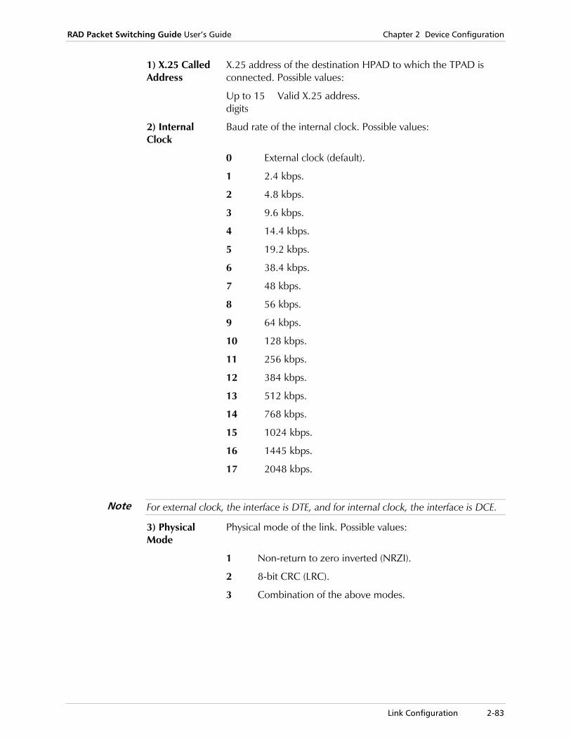
RAD Packet Switching Guide User’s Guide Chapter 2 Device Configuration
Link Configuration 2-83
1) X.25 Called Address
X.25 address of the destination HPAD to which the TPAD is connected. Possible values:
Up to 15 digits
Valid X.25 address.
2) Internal Clock
Baud rate of the internal clock. Possible values:
0 External clock (default).
1 2.4 kbps.
2 4.8 kbps.
3 9.6 kbps.
4 14.4 kbps.
5 19.2 kbps.
6 38.4 kbps.
7 48 kbps.
8 56 kbps.
9 64 kbps.
10 128 kbps.
11 256 kbps.
12 384 kbps.
13 512 kbps.
14 768 kbps.
15 1024 kbps.
16 1445 kbps.
17 2048 kbps.
For external clock, the interface is DTE, and for internal clock, the interface is DCE.
3) Physical Mode
Physical mode of the link. Possible values:
1 Non-return to zero inverted (NRZI).
2 8-bit CRC (LRC).
3 Combination of the above modes.
Note
Chapter 2 Device Configuration RAD Packet Switching Guide User’s Guide
2-84 Link Configuration
4) Protocol Mode
Mode of packets acknowledgement. Possible values:
1 Acknowledge by RVI.
2 Send Temporary Transmission Delay (TTD) packet during transmission.
3 Combination of the above modes.
Only change this parameter if necessary.
5) HPAD group ID
Number of the destination HPAD group to which the TPAD is connected. Possible values:
Any valid Bisync PAD number
The number of the destination HPAD group. The default value is 0.
6) Bisync Type Type of the Bisync link. Possible values:
1 Burroughs (default).
2 BS3 EBCDIC.
3 BS3 ASCII.
4 BS1 EBCDIC.
5 BS1 ASCII (default).
7) CU Number Number of the Control Unit attached to the TPAD. This parameter is used only with IBM Bisync. Possible values:
0 - 31 The number of the controller attached to the TPAD. For example, for polling address C1, use controller 1. The default value is 0.
8) Min Bisync Address
Lowest remote terminal address from which the HPAD scanning process begins. Possible values:
0 - 31 For IBM type.
0 - 99 For Burroughs type.
9) Max Bisync Address
Highest remote terminal address at which the HPAD scanning process ends. Possible values:
0 - 31 For IBM type.
0 - 99 For Burroughs type.
10) Buffer Flow Control
Number of buffers to be allocated for the HDLC link. Possible values: Any number. The default value is 0.
RAD recommends not changing the default settings of parameters 11 to 18.
Note
Caution

RAD Packet Switching Guide User’s Guide Chapter 2 Device Configuration
Link Configuration 2-85
11) Scan Duration
Time in clock ticks through which the HPAD scans the remote terminals. Possible values:
0 No scanning.
1 - 255 Number of clock ticks (1 clock tick = 50 ms. The default value is 1.
12) Scan Retries
Number of times that the HPAD performs an unsuccessful scan, before a decision that the other side is inactive. Possible values:
0 - 255 Number of retries. The default value is 0.
13)Poll Duration
Time in clock ticks through which the HPAD polls the remote terminals. Possible values:
0 No disconnection after inactivity.
1 - 255 Number of clock ticks (1 clock tick = 50 ms. The default value is 2.
14) Poll Retries Number of poll retries, before the decision that the other side is inactive. Possible values:
0 No disconnection after inactivity (default).
1 - 255 Number of retries.
15) Data Duration
Amount of time that the TPAD waits for data after sending an ACK. Possible values:
0 No disconnection after inactivity.
1 - 255 Number of clock ticks (1 clock tick = 50 ms. The default value is 5.
16) Data Retries
Number of retries of waiting for data, after sending an ACK, before the TPAD decides the other side is inactive. Possible values:
0 No disconnection after inactivity.
1 - 255 Number of retries. The default value is 3.
17) Select Duration
Amount of time the TPAD will wait for an ACK, after sending data. Possible values:
0 No disconnection after inactivity.
1 - 255 Number of clock ticks (1 clock tick = 50 ms. The default value is 3.
18) Select Retries
Number of retries of waiting for an ACK, after sending data, before the TPAD decides the other side is inactive. Possible values:
0 No disconnection after inactivity.
1 - 255 Number of retries. The default value is 3.

Chapter 2 Device Configuration RAD Packet Switching Guide User’s Guide
2-86 Link Configuration
19) BSC1 Contention Timer
Time interval between the reception of an ENQ inquiry packet on the BSC interface, and the response from the remote device. Until this interval expires, the SPS discards other ENQ inquiries in order to receive an acknowledgement (ACK) message from the remote device. This parameter is applicable for BSC1 only. Possible values:
1 - 255 A unit of 50 ms. The default value is 2.
20) TTD Timer Temporary Transmission Delay (TTD) timer. Maximum time that the SPS waits to receive data from the X.25 remote device, before sending a TTD packet to the local bisync device. Possible values:
1 - 255 A unit of 50 ms. The default value is 40.
21) WACK Timer
Wait Acknowledgement (WACK) timer. Maximum time that the SPS waits to receive a response from the remote device. Possible values:
1 - 255 A unit of 50 ms. The default value is 4.
Ethernet Link Configuration Use the Ethernet Link n Configuration menu to display and update the parameters of an Ethernet link.
An Ethernet link requires the configuration of three main sets of parameters:
• Operation mode
• Interface configuration
• Bridging configuration.
To use the Ethernet Link n Configuration menu:
1. In the Link Configuration menu, select 3 (Update Link Parameters) and press <Enter>.
A list of links and their corresponding protocol types appears.
2. Type the number of the Ethernet link you want and press <Enter>. The Ethernet Link n Configuration menu appears.
Ethernet Link 8 configuration
---------------------------------
1) Operation mode.
2) Interface configuration.
3) Bridging configuration.
CR) Exit
Select:
Figure 2-38. Ethernet Link n Configuration Menu

RAD Packet Switching Guide User’s Guide Chapter 2 Device Configuration
Link Configuration 2-87
3. Type the number of a function and press <Enter>. The appropriate menu appears.
4. To return to the list of links, press <Enter> without selecting an option.
Ethernet Operation Mode
Use the Operation Mode menu to display and update parameters that control the transfer of data over the Ethernet link.
Operation Mode
---------------
1) IP handling ........... [ 1 ]
2) LLC handling .......... [ 0 ]
3) Bridging handling ..... [ 0 ]
S) Save.
CR) Exit
Select:
Figure 2-39. Ethernet Operation Mode Screen
1) IP Handling Transfer of IP packets according to the device’s IP configuration (see IP Routing on page 2-166). Possible values:
0 IP transfer disabled.
1 IP transfer enabled (default).
2) LLC Handling
Transfer of LLC packets according to the device’s SDLC configuration. Possible values:
0 LLC transfer disabled (default).
1 LLC transfer enabled.
3) Bridging Handling
Transfer of data according to the port’s bridging configuration. Possible values:
0 Bridging disabled (default).
1 Bridging enabled.

Chapter 2 Device Configuration RAD Packet Switching Guide User’s Guide
2-88 Link Configuration
Ethernet Interface Configuration
Use the Interface Configuration screen to display and update the Ethernet link parameters.
Interface configuration
------------------------
1) MAC Address ........... [0000 0000 0000]
2) BandWidth ............. [ 0 ]
S) Save.
CR) Exit
Select:
Figure 2-40. Ethernet Interface Configuration Screen
1) MAC Address
This value is used to define a different MAC address for this link other than the device’s MAC address. If this parameter’s default value is not changed, the link uses the device’s MAC address. Otherwise, the link uses the MAC address defined here. Possible values: 3 sets of 4 hexadecimal digits with a space between each set. The default value is 0000 0000 0000.
2) Bandwidth Allocated bandwidth of the port to Ethernet LAN segment. Possible values:
0 0.5 Mbps (default).
1 1.0 Mbps.
2 1.5 Mbps.
3 2.0 Mbps.
4 2.5 Mbps.
5 3.0 Mbps.
6 3.5 Mbps.
7 4.0 Mbps.
8 4.5 Mbps.
9 5.0 Mbps.
10 5.5 Mbps.
11 6.0 Mbps.
12 6.5 Mbps.
13 7.0 Mbps.
14 7.5 Mbps.
15 8.0 Mbps.

RAD Packet Switching Guide User’s Guide Chapter 2 Device Configuration
Link Configuration 2-89
Ethernet Bridging Configuration
Use the Bridging Configuration screen to display and update the Ethernet bridging data. This function is applicable only if Bridging handling was enabled in the Ethernet Link n Configuration screen.
Bridging Configuration
-----------------------
Active only if Bridging Handling is enabled*.
STATUS: Disabled
D) Point to Point destination ....... [No Dest]
Filter Table
============
ID| Dest MAC Address | Protocol Type | Destination
--|------------------|-----------------|---------------------------
1 |
2 |
3 |
4 |
5 |
6 |
7 |
8 |
9 |
10|
S) Save.
CR) Exit
Select:
Figure 2-41. Bridging Configuration Screen
D) Point to Point Destination
Destination ID of the remote equipment connected to this link. Possible values:
No Dest 0 No destination - bridging is disabled.
Port:LCN ID if the destination uses X.25 PVC.
X.25 address ID if the destination uses X.25 SVC.
cid 1-200 Predefined Call ID number if the destination uses X.25 SVC.
Port:DLCI ID if the destination uses Frame Relay.
Chapter 2 Device Configuration RAD Packet Switching Guide User’s Guide
2-90 Link Configuration
If D is set to No Dest, the device will send bridging data according to destinations configured in the Filter Table. To open a Filter Table entry, type the appropriate ID number (1 - 10). If necessary, change parameters (see below).
These X.25 and/or Frame Relay destinations must also be configured in the Ethernet Global Parameters screen (see Ethernet Global Parameters on page 2-96).
Dest MAC Address
MAC address of the device connected on the other end of this Ethernet link. Possible values:
3 sets of 4 hexadecimal digits.
Valid MAC address.
B Broadcasting.
0 Any address.
Protocol Type Type of protocol encapsulated over this Ethernet link. Possible values:
I IP.
L LLC.
A AppleTalk.
0 Any protocol.
Protocol Four Hexadecimal numbers (XXXX)
Destination Destination ID for equipment connected to the device over an Ethernet LAN. Possible values:
Port:LCN ID if the destination uses X.25 PVC.
X.25 address ID if the destination uses X.25 SVC.
cid 1-200 Predefined Call ID number if the destination uses X.25 SVC.
Port:DLCI ID if the destination uses Frame Relay.
N No destination.

RAD Packet Switching Guide User’s Guide Chapter 2 Device Configuration
System Configuration 2-91
2.4 System Configuration
From the System Configuration menu, you can:
• Update the device system parameters
• Define the priority parameters for transmission from the device
• Set global device parameters for communication with Ethernet LANs
• Define PAP/CHAP authentication security information for the device.
To use the System Configuration menu:
1. In the Configuration menu, select 4 (System Parameters) and press <Enter>. The System Configuration menu appears.
System Configuration
----------------------
1. System Parameters
2. Priority Parameters
3. Ethernet Global Parameters
4. PAP/CHAP Configuration Table
CR) Exit
Select:
Figure 2-42. System Configuration Menu
2. Type the number of a function and press <Enter>. The appropriate menu appears.
3. To return to the Configuration menu, press <Enter> without selecting an option.
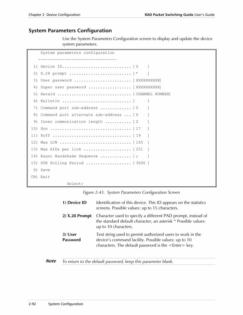
Chapter 2 Device Configuration RAD Packet Switching Guide User’s Guide
2-92 System Configuration
System Parameters Configuration Use the System Parameters Configuration screen to display and update the device system parameters.
System parameters configuration
---------------------------------
1) Device ID............................. [0 ]
2) X.28 prompt .......................... [* ]
3) User password ........................ [XXXXXXXXXX]
4) Super user password .................. [XXXXXXXXXX]
5) Herald ............................... [CHANNEL NUMBER]
6) Bulletin ............................. [ ]
7) Command port sub-address ............. [0 ]
8) Command port alternate sub-address ... [0 ]
9) Inner communication length ........... [2 ]
10) Xon .................................. [17 ]
11) Xoff ................................. [19 ]
12) Max LCN .............................. [165 ]
13) Max AIDs per link .................... [251 ]
14) Async Handshake Sequence ............. [; ]
15) DTR Polling Period ................... [3000 ]
S) Save
CR) Exit
Select:
Figure 2-43. System Parameters Configuration Screen
1) Device ID Identification of this device. This ID appears on the statistics screens. Possible values: up to 15 characters.
2) X.28 Prompt Character used to specify a different PAD prompt, instead of the standard default character, an asterisk * Possible values: up to 10 characters.
3) User Password
Text string used to permit authorized users to work in the device’s command facility. Possible values: up to 10 characters. The default password is the <Enter> key.
To return to the default password, keep this parameter blank.
Note

RAD Packet Switching Guide User’s Guide Chapter 2 Device Configuration
System Configuration 2-93
4) Super User Password
Same function as the User Password. However, when the super user password differs from the user password, persons with regular password access can only perform functions that do not change system status. Possible values: up to 10 characters.
5) Herald Message sent to the terminal screen when the device is reset or when a call ends. Possible values: up to 32 characters. The default herald message is: [device name] [channel number]. The device automatically adds the channel number.
A long herald message reduces the non-volatile storage capacity available for additional profiles and other data.
6) Bulleting Optional text string that is sent to the terminal when a call ends. Possible values: up to 32 characters.
A long bulletin reduces the non-volatile storage capacity available for additional profiles and other data.
7) Command Port Subaddress
Subaddress of the command port. Possible values: 0 – 255. The default value is 0.
8) Command Port Alternate Subaddress
Alternative subaddress of the command port. Possible values: 0 – 255. The default value is 0.
9) Inner Communication Length
Number of digits in the Inner Communication address. When an X.28 Call Connect (CON) command (see X.28 Call Connect Command in Chapter 4) is issued, the address is used to connect to Inner device asynchronous channels or to connect to sites outside the device. If the address length is equal to or less than this parameter, the connection will be made to one of the Inner device channels (according to the specified address). If the address length is greater than this parameter, the connection will be made to an address outside of the device. Possible values:
1 – 5 Number of digits. The default value is 2.
10) X-ON Software flow control character that starts/renews data transfer in the device channels. Possible values: ASCII code of the required character. The default value is 17 (character DC1).
11) X-OFF Software flow control character that stops data transfer in the device channels. Possible values: ASCII code of the required character. The default value is 19 (character DC3).
Note
Note
Chapter 2 Device Configuration RAD Packet Switching Guide User’s Guide
2-94 System Configuration
12) Max LCN Maximum number of logical channels that can be configured in the device. Possible values: ASCII code of the required character.
1 – 12100 Number of logical channels (in accordance with the specific device). The default value is 165.
The Max LCN is the total amount of available LCNs for all ports.
13) Max AID per link
Maximum number of AIDs per link. An AID is the Address ID of the MPE Protocol packet. Possible values:
0 – 251 Number of AIDs. The default value is 251.
14) ASYNC Handshake Sequence
Optional. Text string used as a confirmation sequence between the pad and terminal after the line is cleared or an RTS line check. In this case, text string no. 1 is entered followed by <Enter>; the device confirms communication by string no. 2. After any other string is entered, the device will reply with the prompt. Possible values: Two text strings of up to 12 characters each, separated by a semicolon (;). For example, String1;String2. To clear this parameter, type ; only.
15) DTR Polling Period
You can configure the period for polling the DTR signal in the asynchronous channels. This signal can be used as a trigger for opening and closing calls. The value should be set in 50 msec steps, otherwise it will be rounded to the nearest value (e.g. 380 will be rounded to 400). Possible values: 300 – 20000 msec. The default value is 3000.
Priority Parameters The values in the Priority Parameters screen define the maximum delay time and queue length for all the priority levels for transmitting data from the device. These levels range from 0 (lowest priority) to 3 (highest priority).
Note
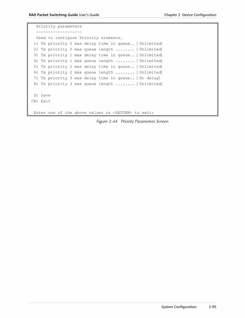
RAD Packet Switching Guide User’s Guide Chapter 2 Device Configuration
System Configuration 2-95
Priority parameters ------------------- Used to configure Priority elements. 1) Tx priority 0 max delay time in queue.. [Unlimited] 2) Tx priority 0 max queue length ........ [Unlimited] 3) Tx priority 1 max delay time in queue.. [Unlimited] 4) Tx priority 1 max queue length ........ [Unlimited] 5) Tx priority 2 max delay time in queue.. [Unlimited] 6) Tx priority 2 max queue length ........ [Unlimited] 7) Tx priority 3 max delay time in queue.. [No delay] 8) Tx priority 3 max queue length ........ [Unlimited] S) Save CR) Exit Enter one of the above values or <RETURN> to exit:
Figure 2-44. Priority Parameters Screen
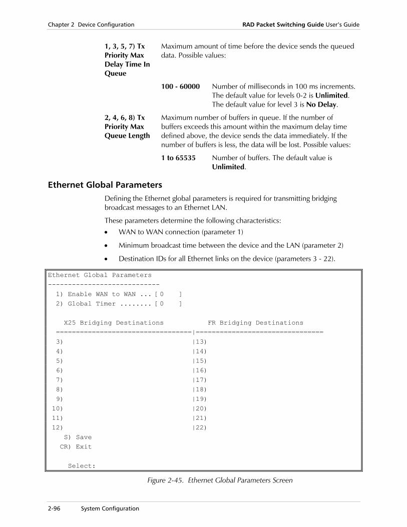
Chapter 2 Device Configuration RAD Packet Switching Guide User’s Guide
2-96 System Configuration
1, 3, 5, 7) Tx Priority Max Delay Time In Queue
Maximum amount of time before the device sends the queued data. Possible values:
100 - 60000 Number of milliseconds in 100 ms increments. The default value for levels 0-2 is Unlimited. The default value for level 3 is No Delay.
2, 4, 6, 8) Tx Priority Max Queue Length
Maximum number of buffers in queue. If the number of buffers exceeds this amount within the maximum delay time defined above, the device sends the data immediately. If the number of buffers is less, the data will be lost. Possible values:
1 to 65535 Number of buffers. The default value is Unlimited.
Ethernet Global Parameters Defining the Ethernet global parameters is required for transmitting bridging broadcast messages to an Ethernet LAN.
These parameters determine the following characteristics:
• WAN to WAN connection (parameter 1)
• Minimum broadcast time between the device and the LAN (parameter 2)
• Destination IDs for all Ethernet links on the device (parameters 3 - 22).
Ethernet Global Parameters ---------------------------- 1) Enable WAN to WAN ... [0 ] 2) Global Timer ........ [0 ] X25 Bridging Destinations FR Bridging Destinations ==================================|================================ 3) |13) 4) |14) 5) |15) 6) |16) 7) |17) 8) |18) 9) |19) 10) |20) 11) |21) 12) |22) S) Save CR) Exit Select:
Figure 2-45. Ethernet Global Parameters Screen

RAD Packet Switching Guide User’s Guide Chapter 2 Device Configuration
System Configuration 2-97
1) Enable WAN to WAN
Enables the device to forward bridged data, which is received from a WAN interface to another WAN interface. Possible values:
0 WAN to WAN bridging disabled (default).
1 WAN to WAN bridging enabled.
2) Global Timer
Minimum time between broadcasts from a LAN station connected to the device. Possible values:
0 Timer is disabled (default).
1 - 255 Number of seconds.
3) X.25 Bridging Destination
Destination ID for X.25 equipment connected to the device over an Ethernet LAN. Possible values:
Port:LCN ID if the destination uses X.25 PVC.
X.25 address ID if the destination uses X.25 SVC.
cid 1-200 Predefined Call ID number if the destination uses X.25 SVC.
4)FR Bridging Destination
Destination ID for Frame Relay equipment connected to the device over an Ethernet LAN.Possible values:
Port:DLCI ID if the destination uses Frame Relay.
PAP/CHAP Authentication Configuration If the device functions as a PPP host, security can be provided by PAP (Password Authentication Protocol) or by CHAP (Challenge Authentication Protocol). These security configurations require the definition of a user ID and a password.
The PAP/CHAP Authentication feature includes the following configuration activities:
• Adding a new PAP/CHAP authentication entry
• Updating an existing PAP/CHAP authentication entry
• Deleting a PAP/CHAP authentication entry
• Displaying the parameters of all PAP/CHAP authentication entries.
This section also contains descriptions of parameters for the authentication configurations.
To use the PAP/CHAP Authentication Table menu:
1. In the Link Configuration menu, select 4 (System Configuration) and press <Enter>.
The System Configuration menu appears.
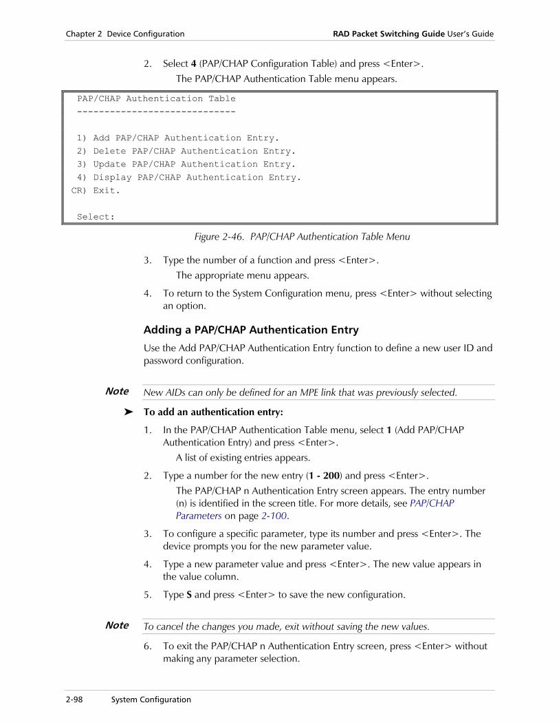
Chapter 2 Device Configuration RAD Packet Switching Guide User’s Guide
2-98 System Configuration
2. Select 4 (PAP/CHAP Configuration Table) and press <Enter>. The PAP/CHAP Authentication Table menu appears.
PAP/CHAP Authentication Table ----------------------------- 1) Add PAP/CHAP Authentication Entry. 2) Delete PAP/CHAP Authentication Entry. 3) Update PAP/CHAP Authentication Entry. 4) Display PAP/CHAP Authentication Entry. CR) Exit. Select:
Figure 2-46. PAP/CHAP Authentication Table Menu
3. Type the number of a function and press <Enter>. The appropriate menu appears.
4. To return to the System Configuration menu, press <Enter> without selecting an option.
Adding a PAP/CHAP Authentication Entry
Use the Add PAP/CHAP Authentication Entry function to define a new user ID and password configuration.
New AIDs can only be defined for an MPE link that was previously selected.
To add an authentication entry:
1. In the PAP/CHAP Authentication Table menu, select 1 (Add PAP/CHAP Authentication Entry) and press <Enter>.
A list of existing entries appears.
2. Type a number for the new entry (1 - 200) and press <Enter>. The PAP/CHAP n Authentication Entry screen appears. The entry number (n) is identified in the screen title. For more details, see PAP/CHAP Parameters on page 2-100.
3. To configure a specific parameter, type its number and press <Enter>. The device prompts you for the new parameter value.
4. Type a new parameter value and press <Enter>. The new value appears in the value column.
5. Type S and press <Enter> to save the new configuration.
To cancel the changes you made, exit without saving the new values.
6. To exit the PAP/CHAP n Authentication Entry screen, press <Enter> without making any parameter selection.
Note
Note
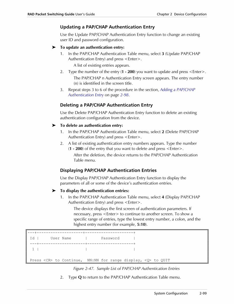
RAD Packet Switching Guide User’s Guide Chapter 2 Device Configuration
System Configuration 2-99
Updating a PAP/CHAP Authentication Entry
Use the Update PAP/CHAP Authentication Entry function to change an existing user ID and password configuration.
To update an authentication entry: 1. In the PAP/CHAP Authentication Table menu, select 3 (Update PAP/CHAP
Authentication Entry) and press <Enter>. A list of existing entries appears.
2. Type the number of the entry (1 - 200) you want to update and press <Enter>. The PAP/CHAP n Authentication Entry screen appears. The entry number (n) is identified in the screen title.
3. Repeat steps 3 to 6 of the procedure in the section, Adding a PAP/CHAP Authentication Entry on page 2-98.
Deleting a PAP/CHAP Authentication Entry
Use the Delete PAP/CHAP Authentication Entry function to delete an existing authentication configuration from the device.
To delete an authentication entry: 1. In the PAP/CHAP Authentication Table menu, select 2 (Delete PAP/CHAP
Authentication Entry) and press <Enter>. 2. A list of existing authentication entry numbers appears. Type the number
(1 - 200) of the entry that you want to delete and press <Enter>. After the deletion, the device returns to the PAP/CHAP Authentication Table menu.
Displaying PAP/CHAP Authentication Entries
Use the Display PAP/CHAP Authentication Entry function to display the parameters of all or some of the device’s authentication entries.
To display the authentication entries: 1. In the PAP/CHAP Authentication Table menu, select 4 (Display PAP/CHAP
Authentication Entry) and press <Enter>. The device displays the first screen of authentication parameters. If necessary, press <Enter> to continue to another screen. To show a specific range of entries, type the lowest entry number, a colon, and the highest entry number (for example, 5:10).
---+--------------------+---------------------+ Id | User Name | Password | ---+--------------------+--------------------+ 1 | | | Press <CR> to Continue, NN:NN for range display, <Q> to QUIT
Figure 2-47. Sample List of PAP/CHAP Authentication Entries
2. Type Q to return to the PAP/CHAP Authentication Table menu.

Chapter 2 Device Configuration RAD Packet Switching Guide User’s Guide
2-100 System Configuration
PAP/CHAP Parameters In the PAP/CHAP n Authentication Entry screen, you define the parameters of each authentication configuration. This feature is applicable if the device functions as a PPP host.
PAP/CHAP 1 Authentication Entry
----------------------------------
1) User Name ...............[ ]
2) Password ................[ ]
S) Save.
CR) Exit.
Select:
Figure 2-48. PAP/CHAP Authentication Entry screen
1) User Name ID of the device. Possible values: Up to 20 alphanumeric characters. To remove this entry, press <Space>.
2) Password Text string required for transferring data to and from the host.

RAD Packet Switching Guide User’s Guide Chapter 2 Device Configuration
PVC Configuration 2-101
2.5 PVC Configuration
A PVC (Permanent Virtual Circuit) is a virtual circuit that has a logical channel permanently assigned to it at the device. The call opens when the device starts up and remains open until the device is disconnected. A PVC can also be opened when a particular configuration becomes active and closed when that configuration is replaced.
From the PVC Configuration menu, you can:
• Add a new PVC
• Update an existing PVC
• Delete a PVC
• Display the list of existing PVCs.
To use the PVC Configuration menu:
1. In the Configuration menu, select 5 (PVC) and press <Enter>. The PVC Configuration menu appears.
PVC configuration
-----------------------------------
1) Add PVC
2) Delete PVC
3) Update PVC
4) Display PVCs
CR) Exit
Select:
Figure 2-49. PVC Configuration Menu
2. Type the number of a function and press <Enter>. The appropriate menu appears.
3. To return to the Configuration menu, press <Enter> without selecting an option.
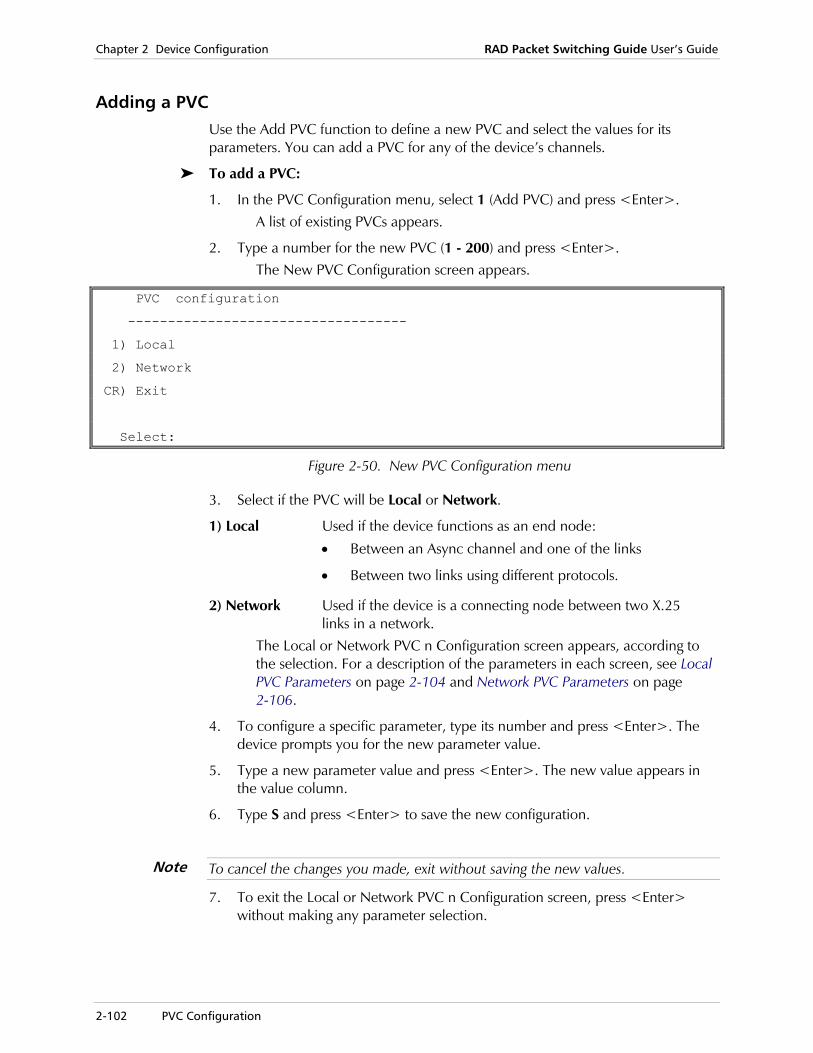
Chapter 2 Device Configuration RAD Packet Switching Guide User’s Guide
2-102 PVC Configuration
Adding a PVC Use the Add PVC function to define a new PVC and select the values for its parameters. You can add a PVC for any of the device’s channels.
To add a PVC:
1. In the PVC Configuration menu, select 1 (Add PVC) and press <Enter>. A list of existing PVCs appears.
2. Type a number for the new PVC (1 - 200) and press <Enter>. The New PVC Configuration screen appears.
PVC configuration
-----------------------------------
1) Local
2) Network
CR) Exit
Select:
Figure 2-50. New PVC Configuration menu
3. Select if the PVC will be Local or Network.
1) Local Used if the device functions as an end node:
• Between an Async channel and one of the links
• Between two links using different protocols.
2) Network Used if the device is a connecting node between two X.25 links in a network.
The Local or Network PVC n Configuration screen appears, according to the selection. For a description of the parameters in each screen, see Local PVC Parameters on page 2-104 and Network PVC Parameters on page 2-106.
4. To configure a specific parameter, type its number and press <Enter>. The device prompts you for the new parameter value.
5. Type a new parameter value and press <Enter>. The new value appears in the value column.
6. Type S and press <Enter> to save the new configuration.
To cancel the changes you made, exit without saving the new values.
7. To exit the Local or Network PVC n Configuration screen, press <Enter> without making any parameter selection.
Note
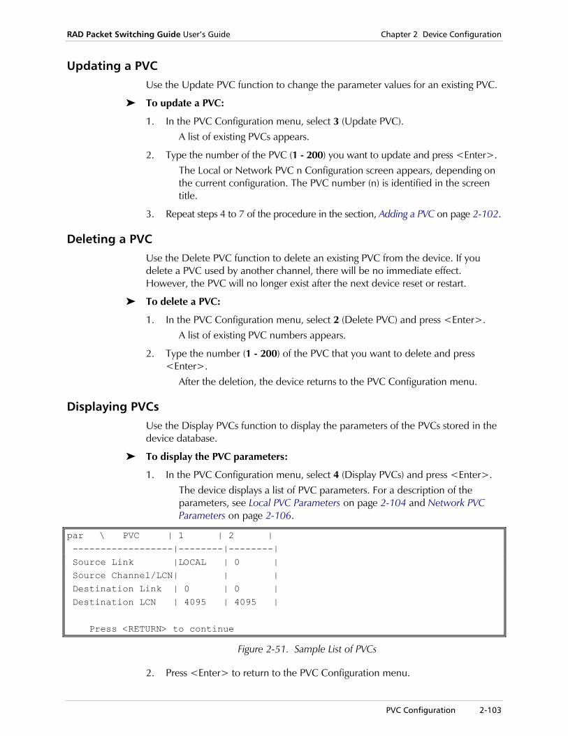
RAD Packet Switching Guide User’s Guide Chapter 2 Device Configuration
PVC Configuration 2-103
Updating a PVC Use the Update PVC function to change the parameter values for an existing PVC.
To update a PVC:
1. In the PVC Configuration menu, select 3 (Update PVC). A list of existing PVCs appears.
2. Type the number of the PVC (1 - 200) you want to update and press <Enter>. The Local or Network PVC n Configuration screen appears, depending on the current configuration. The PVC number (n) is identified in the screen title.
3. Repeat steps 4 to 7 of the procedure in the section, Adding a PVC on page 2-102.
Deleting a PVC Use the Delete PVC function to delete an existing PVC from the device. If you delete a PVC used by another channel, there will be no immediate effect. However, the PVC will no longer exist after the next device reset or restart.
To delete a PVC:
1. In the PVC Configuration menu, select 2 (Delete PVC) and press <Enter>. A list of existing PVC numbers appears.
2. Type the number (1 - 200) of the PVC that you want to delete and press <Enter>.
After the deletion, the device returns to the PVC Configuration menu.
Displaying PVCs Use the Display PVCs function to display the parameters of the PVCs stored in the device database.
To display the PVC parameters:
1. In the PVC Configuration menu, select 4 (Display PVCs) and press <Enter>. The device displays a list of PVC parameters. For a description of the parameters, see Local PVC Parameters on page 2-104 and Network PVC Parameters on page 2-106.
par \ PVC | 1 | 2 | ------------------|--------|--------| Source Link |LOCAL | 0 | Source Channel/LCN| | | Destination Link | 0 | 0 | Destination LCN | 4095 | 4095 | Press <RETURN> to continue
Figure 2-51. Sample List of PVCs
2. Press <Enter> to return to the PVC Configuration menu.

Chapter 2 Device Configuration RAD Packet Switching Guide User’s Guide
2-104 PVC Configuration
Local PVC Parameters When you are configuring a PAD, the Local PVC is defined as a PVC from or to a local channel. The Local PVC is used if the device functions as an end node:
• Between an Async channel and one of the links
• Between two links using different protocols.
Local PVC 1 configuration
------------------------------
1) Channel number .. [ ]
2) Link ID ......... [ ]
3) LCN/DLCI......... [ ]
S) Save
CR) Exit
Select:
Figure 2-52. Local PVC Configuration Screen
1) Channel Number
ID of an Asynchronous channel or HDLC link that will be connected through this PVC to an external X.25 link. Possible values:
up to 6 digits Number of Asynchronous channel.
HxM Main PVC. Used if connecting a transparent HDLC over X.25 encapsulated link through the PVC.x indicates the HDLC link number.
HxB Backup PVC. Used if connecting a transparent HDLC over X.25 encapsulated link through the PVC.x indicates the HDLC link number.
Nx Used if encapsulating MPE over an X.25 PVC link. x indicates a valid MPE link number.
IP address Used if encapsulating an IP over an X.25 PVC link.
BRG Used if encapsulating Ethernet bridging over an X.25 PVC link.

RAD Packet Switching Guide User’s Guide Chapter 2 Device Configuration
PVC Configuration 2-105
2) Link ID Number of the device’s synchronous link that will be connected through the PVC. Possible values: The default value is 0.
0 PVC is not active (default).
1 - number of links on device
Any valid X.25 or Frame Relay link number.
• The Link ID must be defined before configuring LCN • When entering a new Link ID value, make sure the current LCN value was not
previously defined for that Link ID (neither as PVC nor SVC).
3) LCN/DLCI Number of the logical channel or DLCI that will be used to establish the PVC. This number should not be within the range of the SVC (Switched Virtual Circuit). This number must be less than the Lowest LCN (LIC) number or (equal to or) greater than the sum of LIC and the total amount of two-way LCNs and the total amount of LCNs. For more information, see X.25 Link Parameters on page 2-35. Possible values:
0 - 255 Valid logical channel number.
16 - 991 or 1024 - 8,388,607
Valid DLCI number. The number of available DLCIs depends on the Header mode (see Frame Relay Link Configuration on page 2-50). If the DLCI does not exist, the system will add it to the port without protocol encapsulation.
If you enter an LCN value assigned to Switched Virtual Circuit (SVC), the device displays an error message.
Notes
Note

Chapter 2 Device Configuration RAD Packet Switching Guide User’s Guide
2-106 PVC Configuration
Network PVC Parameters The Network PVC is used when defining a PVC through a network link. The Network PVC configuration includes both source and destination parameters.
Network PVC 3 configuration --------------------------------- Source Destination ------------- ------------- 1) Link ID ......... [ ] 3) Link ID .........[ ] 2) LCN/DLCI......... [ ] 4) LCN/DLCI.........[ ] S) Save CR) Exit Select:
Figure 2-53. Network PVC Configuration Screen
1,3) Link ID Numbers of the source device’s synchronous link (parameter 1) and destination device’s synchronous link (parameter 3) that will be connected through the PVC.A single port (link) may be used for one or more PVCs as long as there are no LCN contradictions (overlapping). Possible values: The default value is 0.
0 PVC is not active (default).
1 - number of links on device
Any valid X.25 or Frame Relay link number.
• The Link ID must be defined before configuring LCN • When entering a new Link ID value, make sure the current LCN value was not
previously defined for that Link ID (neither as PVC nor SVC).
2,4) LCN/DLCI Number of the source (parameter 2) or destination (parameter 4) logical channel or DLCI that will be used to establish the PVC. This number should not be within the range of the SVC (Switched Virtual Circuit). This number must be less than the Lowest LCN (LIC) number or (equal to or) greater than the sum of LIC and the total amount of two-way LCNs and the total amount of LCNs. For more information, see X.25 Link Parameters on page 2-35. Possible values:
0 - 255 Valid logical channel number.
16 – 991 or 1024 - 8,388,607
Valid DLCI number. The number of available DLCIs depends on the Header mode (see Frame Relay Link Configuration on page 2-50). If the DLCI does not exist, the system will add it to the port without protocol encapsulation.
Notes
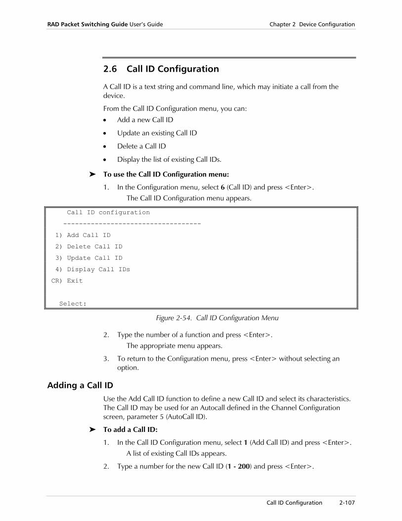
RAD Packet Switching Guide User’s Guide Chapter 2 Device Configuration
Call ID Configuration 2-107
2.6 Call ID Configuration
A Call ID is a text string and command line, which may initiate a call from the device.
From the Call ID Configuration menu, you can:
• Add a new Call ID
• Update an existing Call ID
• Delete a Call ID
• Display the list of existing Call IDs.
To use the Call ID Configuration menu:
1. In the Configuration menu, select 6 (Call ID) and press <Enter>. The Call ID Configuration menu appears.
Call ID configuration
-----------------------------------
1) Add Call ID
2) Delete Call ID
3) Update Call ID
4) Display Call IDs
CR) Exit
Select:
Figure 2-54. Call ID Configuration Menu
2. Type the number of a function and press <Enter>. The appropriate menu appears.
3. To return to the Configuration menu, press <Enter> without selecting an option.
Adding a Call ID Use the Add Call ID function to define a new Call ID and select its characteristics. The Call ID may be used for an Autocall defined in the Channel Configuration screen, parameter 5 (AutoCall ID).
To add a Call ID:
1. In the Call ID Configuration menu, select 1 (Add Call ID) and press <Enter>. A list of existing Call IDs appears.
2. Type a number for the new Call ID (1 - 200) and press <Enter>.

Chapter 2 Device Configuration RAD Packet Switching Guide User’s Guide
2-108 Call ID Configuration
The Call ID n Configuration screen appears. For a description of the parameters, see Call ID Parameters on page 2-110.
3. To configure a specific parameter, type its number and press <Enter>. The device prompts you for the new parameter value.
4. Type a new parameter value and press <Enter>. The new value appears in the value column.
5. Type S and press <Enter> to save the new configuration.
To cancel the changes you made, exit without saving the new values
6. To exit the Call ID n Configuration screen, press <Enter> without making any parameter selection.
Updating a Call ID Use the Update Call ID function to display and change the parameters of an existing Call ID.
To update a Call ID:
1. In the Call ID Configuration menu, select 3 (Update Call ID). A list of existing Call IDs appears.
2. Type the number of the Call ID (1 - 200) you want to update and press <Enter>.
The Call ID n Configuration screen appears. The Call ID number (n) is identified in the screen title.
3. Repeat steps 3 to 6 of the procedure in the section, Adding a Call ID on page 2-107.
The updated parameter values can be loaded for immediate effect, or saved so that they take effect the next time the Call ID is used.
Deleting a Call ID Use the Delete Call ID function to delete an existing Call ID.
To delete a Call ID:
1. In the Call ID Configuration menu, select 2 (Delete Call ID) and press <Enter>.
A list of existing Call ID numbers appears.
2. Type the number (1 - 200) of the Call ID that you want to delete and press <Enter>.
After the deletion, the device returns to the Call ID Configuration menu.
Displaying Call IDs Use the Display Call IDs function to display the parameters of all or some of the Call IDs stored in the device database.
Note

RAD Packet Switching Guide User’s Guide Chapter 2 Device Configuration
Call ID Configuration 2-109
To display the Call ID parameters:
1. In the Call ID Configuration menu, select 4 (Display Call IDs) and press <Enter>.
The device displays a list of Call ID parameters. For a description of the parameters, see Call ID Parameters on page 2-110.
\ Call
Par \ ID| 1 |
--------|--------------|
Mnemonic| |
Command | |
Press <RETURN> to continue
Figure 2-55. Sample List of Call IDs
2. Press <Enter> to return to the Call ID Configuration menu.
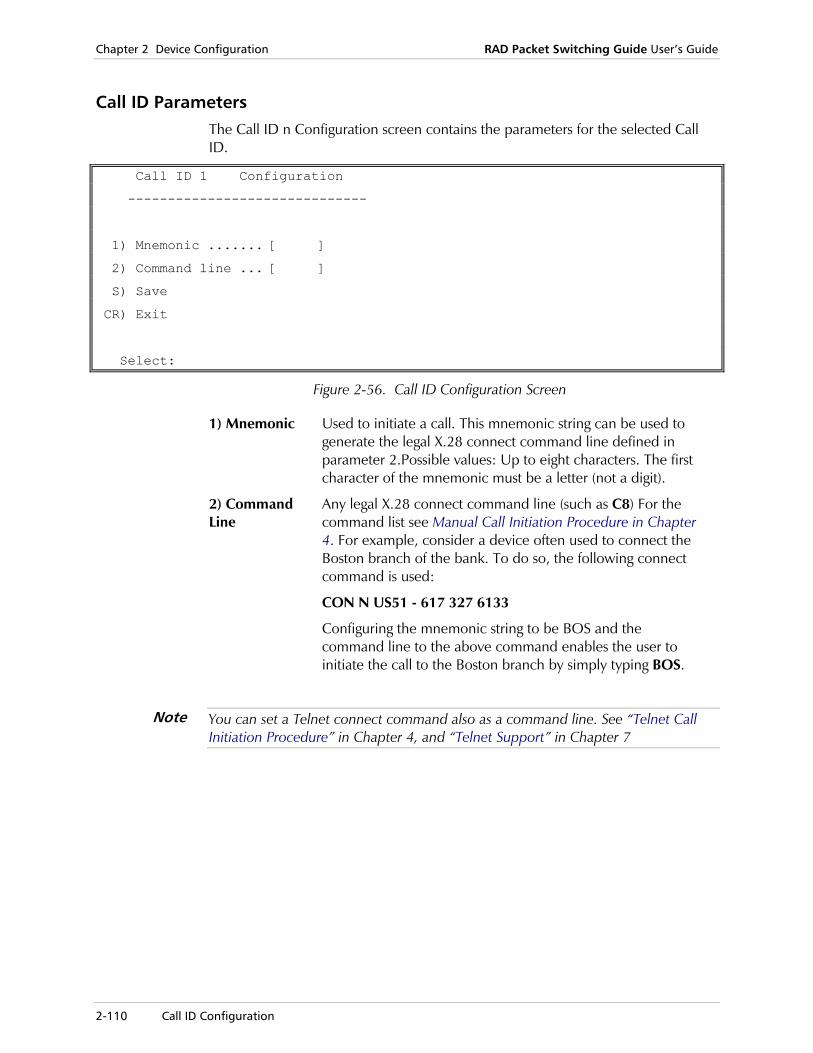
Chapter 2 Device Configuration RAD Packet Switching Guide User’s Guide
2-110 Call ID Configuration
Call ID Parameters The Call ID n Configuration screen contains the parameters for the selected Call ID.
Call ID 1 Configuration
------------------------------
1) Mnemonic ....... [ ]
2) Command line ... [ ]
S) Save
CR) Exit
Select:
Figure 2-56. Call ID Configuration Screen
1) Mnemonic Used to initiate a call. This mnemonic string can be used to generate the legal X.28 connect command line defined in parameter 2.Possible values: Up to eight characters. The first character of the mnemonic must be a letter (not a digit).
2) Command Line
Any legal X.28 connect command line (such as C8) For the command list see Manual Call Initiation Procedure in Chapter 4. For example, consider a device often used to connect the Boston branch of the bank. To do so, the following connect command is used:
CON N US51 - 617 327 6133
Configuring the mnemonic string to be BOS and the command line to the above command enables the user to initiate the call to the Boston branch by simply typing BOS.
You can set a Telnet connect command also as a command line. See “Telnet Call Initiation Procedure” in Chapter 4, and “Telnet Support” in Chapter 7
Note
RAD Packet Switching Guide User’s Guide Chapter 2 Device Configuration
NUI Configuration 2-111
2.7 NUI Configuration
The RAD device support of the NUI (Network User ID) facility offers another means of network security and management control. The device uses the NUI to identify the calling DTE and sort out unauthorized calls. When the NUI is active, any call requests entering the device that have missing or invalid NUIs will be cleared and not forwarded.
In addition, the NUI facility can use the calling address to sort out unauthorized incoming call requests. The incoming NUI and calling addresses are compared with a predefined NUI and calling address list. Only calls bearing one of the specified NUIs and its correlating calling address are accepted.
The device may be configured to forward calls bearing one NUI with a different one. This may be used to provide several connected DTEs, each bearing a different NUI, access to a network requesting a single NUI. This feature can be implemented for call addresses also (i.e. the call entering the device will be forwarded with a different calling address).
For information concerning NUI connect command, see Manual Call Initiation Procedure in Chapter 4.
Assigning an NUI GROUP ID number to either an X.25 link or an Async channel activates the NUI facilities.
When an NUI Group ID number is assigned to an X.25 link, call requests entering the device through that link will be allowed only if they bear one of the specified NUIs).
When an NUI Group ID number is assigned to an Async channel, call requests entering the device through that channel will be allowed only if they bear one of the specified NUIs.
After the call is accepted, it is forwarded with the NUI Out and Address Out defined for the call’s NUI In.
Several NUI In and Address In (and NUI Out and Address Out) values may be assigned to the same Group ID number.
The NUI facility is configured into the device by creating a database presented by the Group ID Table option of the NUI configuration sub-menu. The NUI Out Table and the Address Out Table options configure the two other database fields separately.
These configuration options are explained later in this section.

Chapter 2 Device Configuration RAD Packet Switching Guide User’s Guide
2-112 NUI Configuration
NUI Database Operations When you enter the NUI database configuration function, the NUI Database Configuration menu provides access to the following operations:
• Creating or updating the NUI Group ID Table
• Creating or updating the NUI Out Table
• Creating or updating the Address Out Table.
To use the NUI Database Configuration menu:
1. In the Configuration menu, select 7 (NUI) and press <Enter>. The NUI Database Configuration menu appears.
NUI data base configuration
---------------------------
1) NUI Group ID table
2) NUI out table
3) Address out table
CR) Exit
Select:
Figure 2-57. NUI Database Configuration Menu
2. Type the number of a function and press <Enter>. The appropriate menu appears. Descriptions of each function are provided later in this section.
3. To return to the Configuration menu, press <Enter> without selecting an option.
NUI Group ID Table Configuration The Group ID table contains the basic configuration of the NUI database. The table is built by configuring several entries. Two parameters of the database, NUI Out and Address Out, are configured separately. These parameters are defined in the NUI Group ID Table by their ID number and, therefore, must be preconfigured.
From the Group Table Configuration menu, you can:
• Add a Group ID table entry
• Delete a Group ID table entry
• Update a Group ID table entry
• Display the Group ID table.
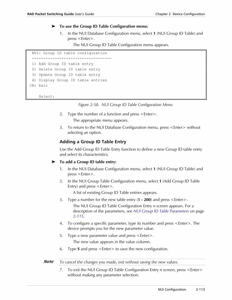
RAD Packet Switching Guide User’s Guide Chapter 2 Device Configuration
NUI Configuration 2-113
To use the Group ID Table Configuration menu:
1. In the NUI Database Configuration menu, select 1 (NUI Group ID Table) and press <Enter>.
The NUI Group ID Table Configuration menu appears.
NUI: Group ID table configuration ----------------------------------- 1) Add Group ID table entry 2) Delete Group ID table entry 3) Update Group ID table entry 4) Display Group ID table entries CR) Exit Select:
Figure 2-58. NUI Group ID Table Configuration Menu
2. Type the number of a function and press <Enter>. The appropriate menu appears.
3. To return to the NUI Database Configuration menu, press <Enter> without selecting an option.
Adding a Group ID Table Entry
Use the Add Group ID Table Entry function to define a new Group ID table entry and select its characteristics.
To add a Group ID table entry:
1. In the NUI Database Configuration menu, select 1 (NUI Group ID Table) and press <Enter>.
2. In the NUI Group Table Configuration menu, select 1 (Add Group ID Table Entry) and press <Enter>.
A list of existing Group ID Table entries appears.
3. Type a number for the new table entry (1 - 200) and press <Enter>. The NUI Group ID Table Configuration Entry n screen appears. For a description of the parameters, see NUI Group ID Table Parameters on page 2-115.
4. To configure a specific parameter, type its number and press <Enter>. The device prompts you for the new parameter value.
5. Type a new parameter value and press <Enter>. The new value appears in the value column.
6. Type S and press <Enter> to save the new configuration.
To cancel the changes you made, exit without saving the new values.
7. To exit the NUI Group ID Table Configuration Entry n screen, press <Enter> without making any parameter selection.
Note

Chapter 2 Device Configuration RAD Packet Switching Guide User’s Guide
2-114 NUI Configuration
Updating a Group ID Table Entry
Use the Update Group ID table entry function to display and change the parameters of an existing Group ID table entry.
To update a Group ID Table Entry:
1. In the NUI Database Configuration menu, select 1 (NUI Group ID Table) and press <Enter>.
2. In the NUI Group Table Configuration menu, select 3 (Update Group ID Table Entry) and press <Enter>.
A list of existing Group ID Table entries appears.
3. Type the number of the table entry (1 - 200) you want to update and press <Enter>.
The NUI Group ID Table Configuration Entry n screen appears. The entry number (n) is identified in the screen title.
4. Repeat steps 4 - 7 of the procedure in the section, Adding a Group ID Table Entry on page 2-113.
Deleting a Group ID Table Entry
Use the Delete Group ID Table Entry function to delete an existing Group ID table entry.
To delete a Group ID Table Entry:
1. In the NUI Database Configuration menu, select 1 (NUI Group ID Table) and press <Enter>.
2. In the NUI Group Table Configuration menu, select 2 (Delete Group ID Table Entry) and press <Enter>.
A list of existing Group ID Table entries appears.
3. Type the number (1 - 200) of the table entry that you want to delete and press <Enter>.
After the deletion, the device returns to the NUI Group Table Configuration menu.
Displaying Group ID Table Entries
Use the Display Group ID table entries function to display the parameters of all or some of the Group ID table entries stored in the device database.
To display the Group ID table entries:
1. In the NUI Database Configuration menu, select 1 (NUI Group ID Table) and press <Enter>.
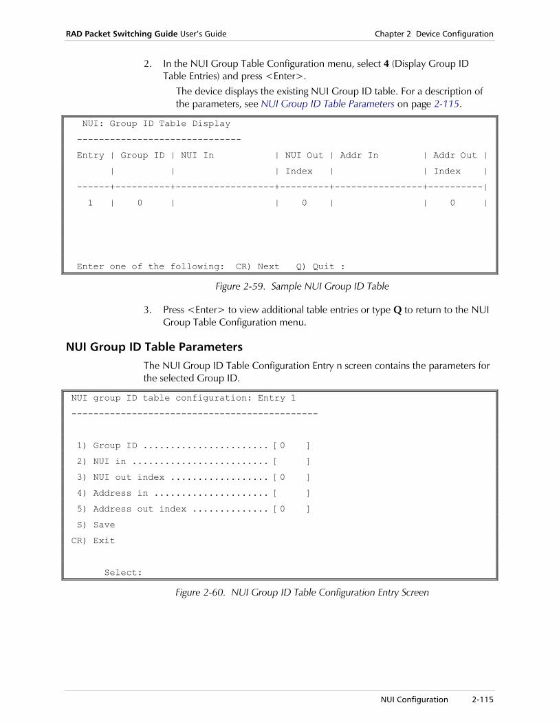
RAD Packet Switching Guide User’s Guide Chapter 2 Device Configuration
NUI Configuration 2-115
2. In the NUI Group Table Configuration menu, select 4 (Display Group ID Table Entries) and press <Enter>.
The device displays the existing NUI Group ID table. For a description of the parameters, see NUI Group ID Table Parameters on page 2-115.
NUI: Group ID Table Display
------------------------------
Entry | Group ID | NUI In | NUI Out | Addr In | Addr Out |
| | | Index | | Index |
------+----------+------------------+---------+----------------+----------|
1 | 0 | | 0 | | 0 |
Enter one of the following: CR) Next Q) Quit :
Figure 2-59. Sample NUI Group ID Table
3. Press <Enter> to view additional table entries or type Q to return to the NUI Group Table Configuration menu.
NUI Group ID Table Parameters The NUI Group ID Table Configuration Entry n screen contains the parameters for the selected Group ID.
NUI group ID table configuration: Entry 1
---------------------------------------------
1) Group ID ....................... [0 ]
2) NUI in ......................... [ ]
3) NUI out index .................. [0 ]
4) Address in ..................... [ ]
5) Address out index .............. [0 ]
S) Save
CR) Exit
Select:
Figure 2-60. NUI Group ID Table Configuration Entry Screen
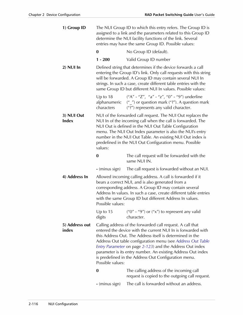
Chapter 2 Device Configuration RAD Packet Switching Guide User’s Guide
2-116 NUI Configuration
1) Group ID The NUI Group ID to which this entry refers. The Group ID is assigned to a link and the parameters related to this Group ID determine the NUI facility functions of the link. Several entries may have the same Group ID. Possible values:
0 No Group ID (default).
1 - 200 Valid Group ID number
2) NUI In Defined string that determines if the device forwards a call entering the Group ID’s link. Only call requests with this string will be forwarded. A Group ID may contain several NUI In strings. In such a case, create different table entries with the same Group ID but different NUI In values. Possible values:
Up to 18 alphanumeric characters
(“A” - “Z”, “a” - “z”, “0” - “9”) underline (“_”) or question mark (“?”). A question mark (“?”) represents any valid character.
3) NUI Out Index
NUI of the forwarded call request. The NUI Out replaces the NUI In of the incoming call when the call is forwarded. The NUI Out is defined in the NUI Out Table Configuration menu. The NUI Out Index parameter is also the NUI's entry number in the NUI Out Table. An existing NUI Out index is predefined in the NUI Out Configuration menu. Possible values:
0 The call request will be forwarded with the same NUI IN.
- (minus sign) The call request is forwarded without an NUI.
4) Address In Allowed incoming calling address. A call is forwarded if it bears a correct NUI, and is also generated from a corresponding address. A Group ID may contain several Address In values. In such a case, create different table entries with the same Group ID but different Address In values. Possible values:
Up to 15 digits
(“0” - “9”) or (“x”) to represent any valid character.
5) Address out index
Calling address of the forwarded call request. A call that entered the device with the current NUI In is forwarded with this Address Out. The Address itself is determined in the Address Out table configuration menu (see Address Out Table Entry Parameter on page 2-123) and the Address Out index parameter is its entry number. An existing Address Out index is predefined in the Address Out Configuration menu. Possible values:
0 The calling address of the incoming call request is copied to the outgoing call request.
- (minus sign) The call is forwarded without an address.
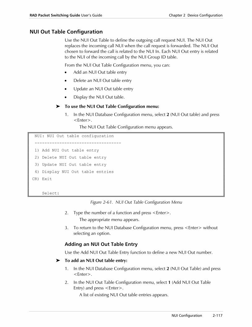
RAD Packet Switching Guide User’s Guide Chapter 2 Device Configuration
NUI Configuration 2-117
NUI Out Table Configuration Use the NUI Out Table to define the outgoing call request NUI. The NUI Out replaces the incoming call NUI when the call request is forwarded. The NUI Out chosen to forward the call is related to the NUI In. Each NUI Out entry is related to the NUI of the incoming call by the NUI Group ID table.
From the NUI Out Table Configuration menu, you can:
• Add an NUI Out table entry
• Delete an NUI Out table entry
• Update an NUI Out table entry
• Display the NUI Out table.
To use the NUI Out Table Configuration menu:
1. In the NUI Database Configuration menu, select 2 (NUI Out table) and press <Enter>.
The NUI Out Table Configuration menu appears.
NUI: NUI Out table configuration
-----------------------------------
1) Add NUI Out table entry
2) Delete NUI Out table entry
3) Update NUI Out table entry
4) Display NUI Out table entries
CR) Exit
Select:
Figure 2-61. NUI Out Table Configuration Menu
2. Type the number of a function and press <Enter>. The appropriate menu appears.
3. To return to the NUI Database Configuration menu, press <Enter> without selecting an option.
Adding an NUI Out Table Entry
Use the Add NUI Out Table Entry function to define a new NUI Out number.
To add an NUI Out table entry:
1. In the NUI Database Configuration menu, select 2 (NUI Out Table) and press <Enter>.
2. In the NUI Out Table Configuration menu, select 1 (Add NUI Out Table Entry) and press <Enter>.
A list of existing NUI Out table entries appears.
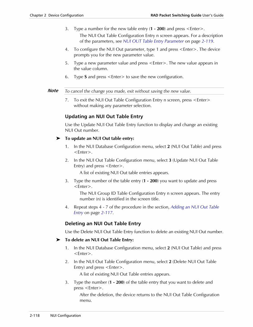
Chapter 2 Device Configuration RAD Packet Switching Guide User’s Guide
2-118 NUI Configuration
3. Type a number for the new table entry (1 - 200) and press <Enter>. The NUI Out Table Configuration Entry n screen appears. For a description of the parameters, see NUI OUT Table Entry Parameter on page 2-119.
4. To configure the NUI Out parameter, type 1 and press <Enter>. The device prompts you for the new parameter value.
5. Type a new parameter value and press <Enter>. The new value appears in the value column.
6. Type S and press <Enter> to save the new configuration.
To cancel the change you made, exit without saving the new value.
7. To exit the NUI Out Table Configuration Entry n screen, press <Enter> without making any parameter selection.
Updating an NUI Out Table Entry
Use the Update NUI Out Table Entry function to display and change an existing NUI Out number.
To update an NUI Out table entry:
1. In the NUI Database Configuration menu, select 2 (NUI Out Table) and press <Enter>.
2. In the NUI Out Table Configuration menu, select 3 (Update NUI Out Table Entry) and press <Enter>.
A list of existing NUI Out table entries appears.
3. Type the number of the table entry (1 - 200) you want to update and press <Enter>.
The NUI Group ID Table Configuration Entry n screen appears. The entry number (n) is identified in the screen title.
4. Repeat steps 4 - 7 of the procedure in the section, Adding an NUI Out Table Entry on page 2-117.
Deleting an NUI Out Table Entry
Use the Delete NUI Out Table Entry function to delete an existing NUI Out number.
To delete an NUI Out Table Entry:
1. In the NUI Database Configuration menu, select 2 (NUI Out Table) and press <Enter>.
2. In the NUI Out Table Configuration menu, select 2 (Delete NUI Out Table Entry) and press <Enter>.
A list of existing NUI Out Table entries appears.
3. Type the number (1 - 200) of the table entry that you want to delete and press <Enter>.
After the deletion, the device returns to the NUI Out Table Configuration menu.
Note
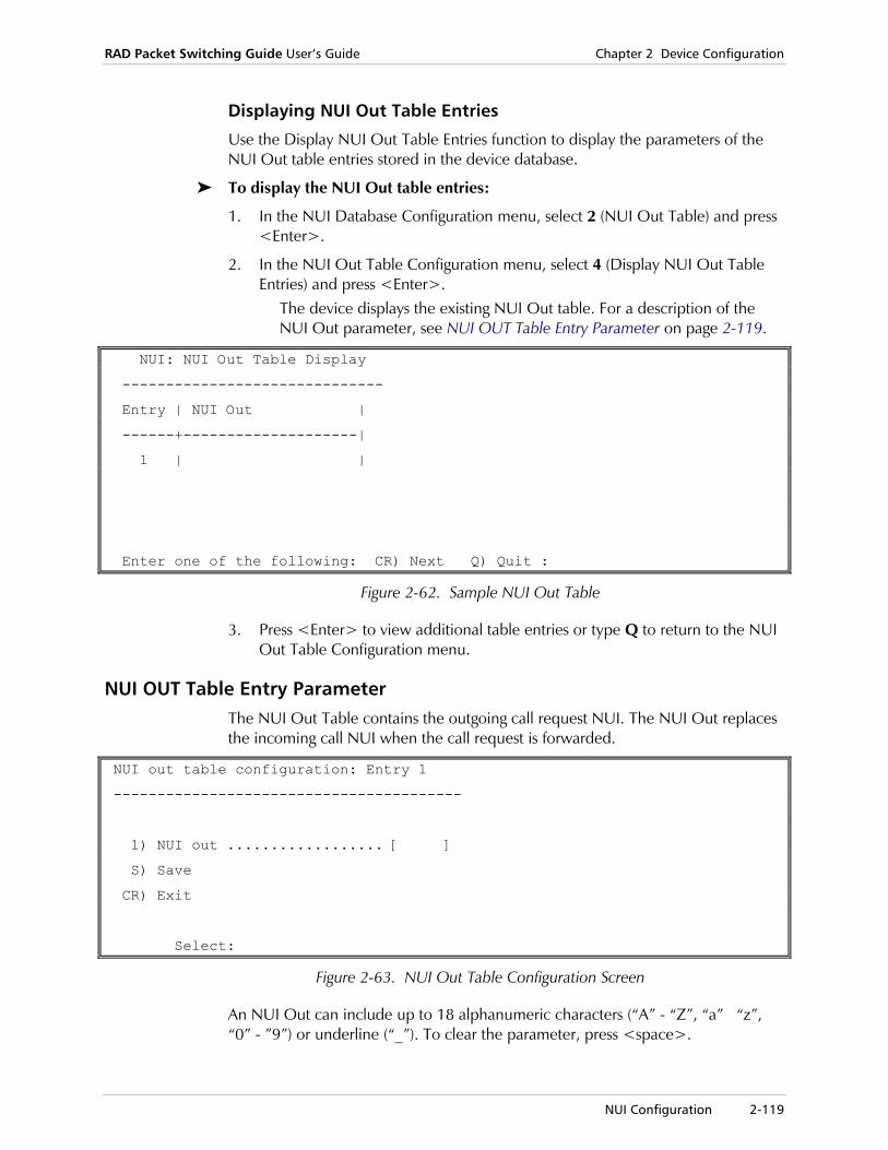
RAD Packet Switching Guide User’s Guide Chapter 2 Device Configuration
NUI Configuration 2-119
Displaying NUI Out Table Entries
Use the Display NUI Out Table Entries function to display the parameters of the NUI Out table entries stored in the device database.
To display the NUI Out table entries:
1. In the NUI Database Configuration menu, select 2 (NUI Out Table) and press <Enter>.
2. In the NUI Out Table Configuration menu, select 4 (Display NUI Out Table Entries) and press <Enter>.
The device displays the existing NUI Out table. For a description of the NUI Out parameter, see NUI OUT Table Entry Parameter on page 2-119.
NUI: NUI Out Table Display
------------------------------
Entry | NUI Out |
------+--------------------|
1 | |
Enter one of the following: CR) Next Q) Quit :
Figure 2-62. Sample NUI Out Table
3. Press <Enter> to view additional table entries or type Q to return to the NUI Out Table Configuration menu.
NUI OUT Table Entry Parameter The NUI Out Table contains the outgoing call request NUI. The NUI Out replaces the incoming call NUI when the call request is forwarded.
NUI out table configuration: Entry 1
----------------------------------------
1) NUI out .................. [ ]
S) Save
CR) Exit
Select:
Figure 2-63. NUI Out Table Configuration Screen
An NUI Out can include up to 18 alphanumeric characters (“A” - “Z”, “a” “z”, “0” - ”9”) or underline (“_”). To clear the parameter, press <space>.

Chapter 2 Device Configuration RAD Packet Switching Guide User’s Guide
2-120 NUI Configuration
Address Out Table Configuration Use the Address Out Table to define the outgoing call request’s calling address. The Address Out replaces the incoming calling address when the call request is forwarded. The calling Address Out chosen to forward the call is related to the NUI In. Each NUI Out entry is related to the NUI Group ID table entry of the incoming call by the NUI Group ID table.
From the Address Out Table Configuration menu, you can:
• Add a new Address Out table entry
• Delete an Address Out table entry
• Update an Address Out table entry
• Display the Address Out table entries.
To use the Address Out Table Configuration menu:
1. In the NUI Database Configuration menu, select 3 (Address Out Table) and press <Enter>.
The Address Out Table Configuration menu appears.
NUI: Address Out table configuration
-----------------------------------
1) Add Address Out table entry
2) Delete Address Out table entry
3) Update Address Out table entry
4) Display Address Out table entries
CR) Exit
Select:
Figure 2-64. Address Out Table Configuration Screen
2. Type the number of a function and press <Enter>. The appropriate menu appears.
3. To return to the NUI Database Configuration menu, press <Enter> without selecting an option.
Adding an Address Out Table Entry
Use the Add Address Out Table Entry function to define a new Address Out number.
To add an Address Out Table Entry
1. In the NUI Database Configuration menu, select 3 (Address Out Table) and press <Enter>.
2. In the Address Out Table Configuration menu, select 1 (Add Address Out Table Entry) and press <Enter>.
A list of existing Address Out table entries appears.

RAD Packet Switching Guide User’s Guide Chapter 2 Device Configuration
NUI Configuration 2-121
3. Type a number for the new table entry (1 - 200) and press <Enter>. The Address Out Table Configuration Entry n screen appears. For a description of the parameters, see Address Out Table Entry Parameter on page 2-123.
4. To configure the Address Out parameter, type 1 and press <Enter>. The device prompts you for the new parameter value.
5. Type a new parameter value and press <Enter>. The new value appears in the value column.
6. Type S and press <Enter> to save the new configuration.
To cancel the change you made, exit without saving the new value.
7. To exit the Address Out Table Configuration Entry n screen, press <Enter> without making any parameter selection.
Updating an Address Out Table Entry
Use the Update Address Out Table Entry function to display and change an existing Address Out number.
To update an Address Out table entry:
1. In the NUI Database Configuration menu, select 3 (Address Out Table) and press <Enter>.
2. In the Address Out Table Configuration menu, select 3 (Update Address Out Table Entry) and press <Enter>.
A list of existing Address Out table entries appears.
3. Type the number of the table entry (1 - 200) you want to update and press <Enter>.
The Address Group ID Table Configuration Entry n screen appears. The entry number (n) is identified in the screen title.
4. Repeat steps 4 - 7 of the procedure in the section, Adding an Address Out Table Entry on page 2-120.
Note

Chapter 2 Device Configuration RAD Packet Switching Guide User’s Guide
2-122 NUI Configuration
Deleting an Address Out Table Entry
Use the Delete Address Out Table Entry function to delete an existing Address Out number.
To delete an Address Out Table Entry:
1. In the NUI Database Configuration menu, select 3 (Address Out Table) and press <Enter>.
2. In the Address Out Table Configuration menu, select 2 (Delete Address Out Table Entry) and press <Enter>.
A list of existing Address Out Table entries appears.
3. Type the number (1 - 200) of the table entry that you want to delete and press <Enter>.
After the deletion, the device returns to the Address Out Table Configuration menu.
Displaying Address Out Table Entries
Use the Display Address Out Table Entries function to display the parameters of the Address Out table entries stored in the device database.
To display the Address Out table entries:
1. In the NUI Database Configuration menu, select 3 (Address Out Table) and press <Enter>.
2. In the Address Out Table Configuration menu, select 4 (Display Address Out Table Entries) and press <Enter>.
The device displays the existing Address Out table. For a description of the Address Out parameter, see Address Out Table Entry Parameter on page 2-123.
NUI: Address Out Table Display
------------------------------
Entry | Addr Out |
------+--------------------|
1 | |
Enter one of the following: CR) Next Q) Quit :
Figure 2-65. Sample Address Out Table
3. Press <Enter> to view additional table entries or type Q to return to the Address Out Table Configuration menu.
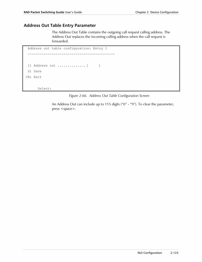
RAD Packet Switching Guide User’s Guide Chapter 2 Device Configuration
NUI Configuration 2-123
Address Out Table Entry Parameter The Address Out Table contains the outgoing call request calling address. The Address Out replaces the incoming calling address when the call request is forwarded.
Address out table configuration: Entry 1
--------------------------------------------
1) Address out .............. [ ]
S) Save
CR) Exit
Select:
Figure 2-66. Address Out Table Configuration Screen
An Address Out can include up to 115 digits (“0” - “9”). To clear the parameter, press <space>.

Chapter 2 Device Configuration RAD Packet Switching Guide User’s Guide
2-124 Alias Configuration
2.8 Alias Configuration
The alias is an alternate text string that is sent to the terminal when a call is opened to an asynchronous channel. The Call Alias parameter of the Channel Configuration (see Channel Configuration on page 2-3) must be an alias entry that was defined in the Alias Configuration. An alias can include up to 64 characters.
From the Alias Configuration menu, you can:
• Add a new alias
• Update an existing alias
• Delete an alias
• Display the list of existing aliases.
To use the Alias Configuration menu:
1. In the Configuration menu, select 8 (Alias) and press <Enter>. The Alias Configuration menu appears.
Alias configuration
-----------------------------------
1) Add Alias
2) Delete Alias
3) Update Alias
4) Display Aliases
CR) Exit
Select:
Figure 2-67. Alias Configuration Menu
2. Type the number of a function and press <Enter>. The appropriate menu appears.
3. To return to the Configuration menu, press <Enter> without selecting an option.

RAD Packet Switching Guide User’s Guide Chapter 2 Device Configuration
Alias Configuration 2-125
Adding an Alias Use the Add Alias function to define a text string as a new alias. To identify the alias entries, you assign them ID numbers.
To add an alias:
1. In the Alias Configuration menu, select 1 (Add Alias) and press <Enter>.
A list of existing alias ID numbers appears.
2. Type an ID number for the new alias (1 - 200) and press <Enter>. The Alias n Configuration screen appears. For a description of the parameters, see ALIAS Parameter on page 2-127.
3. To enter the alias, type 1 and press <Enter>. The device prompts you for the new parameter value.
4. Type a new alias and press <Enter>. The new alias appears in the value column.
5. Type S and press <Enter> to save the new configuration.
To cancel the changes you made, exit without saving the new values.
6. To exit the Alias n Configuration screen, press <Enter> without making any parameter selection.
Updating an Alias Use the Update Alias function to display and change an existing alias.
To update an alias:
1. In the Alias Configuration menu, select 3 (Update Alias). A list of existing alias ID numbers appears.
2. Type the ID number of the alias (1 - 200) you want to update and press <Enter>.
The Alias n Configuration screen appears. The alias ID number (n) is identified in the screen title.
3. Repeat steps 3 - 6 of the procedure in the section, Adding an Alias on page 2-125.
The updated alias can be saved so that it takes effect the next time the alias is used.
Note
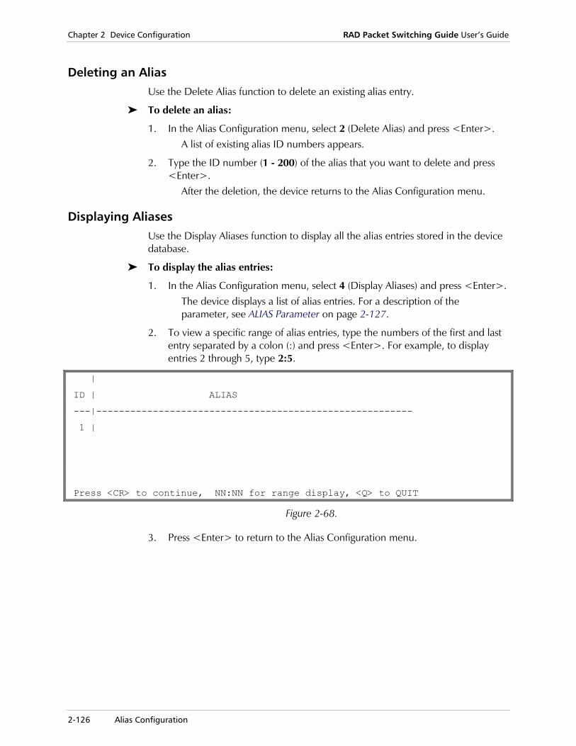
Chapter 2 Device Configuration RAD Packet Switching Guide User’s Guide
2-126 Alias Configuration
Deleting an Alias Use the Delete Alias function to delete an existing alias entry.
To delete an alias:
1. In the Alias Configuration menu, select 2 (Delete Alias) and press <Enter>. A list of existing alias ID numbers appears.
2. Type the ID number (1 - 200) of the alias that you want to delete and press <Enter>.
After the deletion, the device returns to the Alias Configuration menu.
Displaying Aliases Use the Display Aliases function to display all the alias entries stored in the device database.
To display the alias entries:
1. In the Alias Configuration menu, select 4 (Display Aliases) and press <Enter>. The device displays a list of alias entries. For a description of the parameter, see ALIAS Parameter on page 2-127.
2. To view a specific range of alias entries, type the numbers of the first and last entry separated by a colon (:) and press <Enter>. For example, to display entries 2 through 5, type 2:5.
|
ID | ALIAS
---|--------------------------------------------------------
1 |
Press <CR> to continue, NN:NN for range display, <Q> to QUIT
Figure 2-68.
3. Press <Enter> to return to the Alias Configuration menu.

RAD Packet Switching Guide User’s Guide Chapter 2 Device Configuration
Alias Configuration 2-127
ALIAS Parameter The Alias n Configuration screen contains the alias string for the selected alias entry.
ALIAS 1 configuration
-----------------------------------
1) Alias ....[ ]
S) Save
CR) Exit
Select:
Figure 2-69. Alias Configuration Screen
An alias can include up to 64 characters.
If you type # followed by the alias number on the command line, (for example: #1), the device will display and forward the alias characters. The alias ID number is also part of the channel configuration (Call Alias). At call setup, the device sends the alias to the caller.

Chapter 2 Device Configuration RAD Packet Switching Guide User’s Guide
2-128 Routing Table Configuration
2.9 Routing Table Configuration
The routing table is a list of route configurations for incoming and outgoing data. During a call, the calling party supplies a destination address. This address is a known location within the network. If the network supports alternate routing, the routing table also defines the link priority (which link to transfer the packets). The routing table is usually configured according to distance or to network load.
The routing table includes entries. Each entry includes an address and up to three destination links.
In this section, the term “destination link” refers to either a synchronous device link, or to a Frame Relay DLCI.
The destination links determine the routing paths. First, the device tries to route transmitted data through the first destination link. If this attempt is unsuccessful, the device tries to route the data through the second destination link (if applicable), and then through the third (if applicable).
The order of the entries in the routing table is important. The address in entry 1 must be more specific than the address in entries 2 and 3. Entries 2 and 3 may include several “don’t care” digits indicated by x. The entry 2 address may even contain the entry 1 address by having more “don’t care” digits.
Each link may have a priority. The device will direct more calls to links with high priorities than to links with low priorities.
The default routing table consists of one entry, entry number 2000 (the last entry), and its address is XXXXXXXXXXXXXXX (all “don't care” digits). Therefore, all packets that were not routed according to previous entries are finally routed according to this entry destination link, which is the local device channels.
From the Routing Table Entry Configuration menu, you can:
• Add a new routing table entry
• Update an existing routing table entry
• Delete a routing table entry
• Display the list of existing routing table entries.
Note
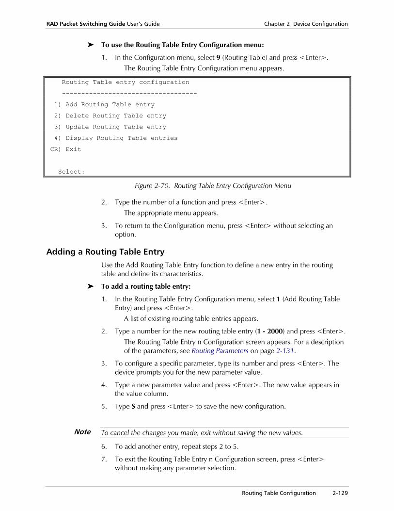
RAD Packet Switching Guide User’s Guide Chapter 2 Device Configuration
Routing Table Configuration 2-129
To use the Routing Table Entry Configuration menu:
1. In the Configuration menu, select 9 (Routing Table) and press <Enter>. The Routing Table Entry Configuration menu appears.
Routing Table entry configuration
-----------------------------------
1) Add Routing Table entry
2) Delete Routing Table entry
3) Update Routing Table entry
4) Display Routing Table entries
CR) Exit
Select:
Figure 2-70. Routing Table Entry Configuration Menu
2. Type the number of a function and press <Enter>. The appropriate menu appears.
3. To return to the Configuration menu, press <Enter> without selecting an option.
Adding a Routing Table Entry Use the Add Routing Table Entry function to define a new entry in the routing table and define its characteristics.
To add a routing table entry:
1. In the Routing Table Entry Configuration menu, select 1 (Add Routing Table Entry) and press <Enter>.
A list of existing routing table entries appears.
2. Type a number for the new routing table entry (1 - 2000) and press <Enter>. The Routing Table Entry n Configuration screen appears. For a description of the parameters, see Routing Parameters on page 2-131.
3. To configure a specific parameter, type its number and press <Enter>. The device prompts you for the new parameter value.
4. Type a new parameter value and press <Enter>. The new value appears in the value column.
5. Type S and press <Enter> to save the new configuration.
To cancel the changes you made, exit without saving the new values.
6. To add another entry, repeat steps 2 to 5.
7. To exit the Routing Table Entry n Configuration screen, press <Enter> without making any parameter selection.
Note
Chapter 2 Device Configuration RAD Packet Switching Guide User’s Guide
2-130 Routing Table Configuration
Updating a Routing Table Entry Use the Update Routing Table Entry function to display and change the parameters of an existing entry in the routing table.
To update an existing routing table entry:
1. In the Routing Table Entry Configuration menu, select 3 (Update Routing Table Entry).
A list of existing routing table entries appears.
2. Type the number of the routing table entry (1 - 200) you want to update and press <Enter>.
The Routing Table Entry n Configuration screen appears. The entry number (n) is identified in the screen title.
3. Repeat steps 3 - 7 of the procedure in the section, Adding a Routing Table Entry on page 2-129.
Deleting a Routing Table Entry Use the Delete Routing Table Entry function to delete an existing entry from the routing table.
To delete a routing table entry:
1. In the Routing Table Entry Configuration menu, select 2 (Delete Routing Table Entry) and press <Enter>.
A list of existing routing table entry numbers appears.
2. Type the number (1 - 200) of the entry that you want to delete and press <Enter>.
After the deletion, the device returns to the Routing Table Entry Configuration menu.
Displaying Routing Table Entries Use the Display Routing Table Entries function to display the parameters of the routing table entries stored in the device database.
To display the routing parameters:
1. In the Routing Table Entry Configuration menu, select 4 (Display Routing Table Entries) and press <Enter>.
The device displays a list of routing parameters. For a description of the parameters, see Routing Parameters on page 2-131.

RAD Packet Switching Guide User’s Guide Chapter 2 Device Configuration
Routing Table Configuration 2-131
2. To view a specific range of routing table entries, type the numbers of the first and last entry separated by a colon (:) and press <Enter>. For example, to display entries 2 through 5, type 2:5.
| | LINK #NO |
ID | ADDRESS | PRIORITY |
----+--------------+-----+-----+-----+
1 | | 0 | 0 | 0 |
S=Y | | 1 | 1 | 1 |
----+--------------+-----+-----+-----+
2000|XXXXXXXXXXXXXX|LOCAL| 0 | 0 |
S=Y | | 1 | 1 | 1 |
----+--------------+-----+-----+-----+
Press <CR> to Continue, NN:NN for range display, <Q> to QUIT
Figure 2-71. Sample Routing Table Entries
3. Press <Enter> to return to the Call ID Configuration menu.
Routing Parameters The Routing Table Entry n Configuration screen contains the destination and priority parameters for the selected routing table.
Routing table entry 1 configuration
-----------------------------------------
1) Link .......... [0 ] ----> 6) Priority ...... [1 ]
2) Link .......... [0 ] ----> 7) Priority ...... [1 ]
3) Link .......... [0 ] ----> 8) Priority ...... [1 ]
4) Address ....... [ ]
5) Stop search ... [1 ]
S) Save
CR) Exit
Select:
Figure 2-72. Routing Table Entry Configuration Screen
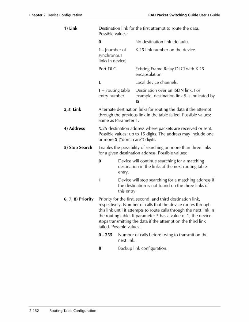
Chapter 2 Device Configuration RAD Packet Switching Guide User’s Guide
2-132 Routing Table Configuration
1) Link Destination link for the first attempt to route the data. Possible values:
0 No destination link (default).
1 - [number of synchronous links in device]
X.25 link number on the device.
Port:DLCI Existing Frame Relay DLCI with X.25 encapsulation.
L Local device channels.
I + routing table entry number
Destination over an ISDN link. For example, destination link 5 is indicated by I5.
2,3) Link Alternate destination links for routing the data if the attempt through the previous link in the table failed. Possible values: Same as Parameter 1.
4) Address X.25 destination address where packets are received or sent. Possible values: up to 15 digits. The address may include one or more X (“don’t care”) digits.
5) Stop Search Enables the possibility of searching on more than three links for a given destination address. Possible values:
0 Device will continue searching for a matching destination in the links of the next routing table entry.
1 Device will stop searching for a matching address if the destination is not found on the three links of this entry.
6, 7, 8) Priority Priority for the first, second, and third destination link, respectively. Number of calls that the device routes through this link until it attempts to route calls through the next link in the routing table. If parameter 5 has a value of 1, the device stops transmitting the data if the attempt on the third link failed. Possible values:
0 - 255 Number of calls before trying to transmit on the next link.
B Backup link configuration.

RAD Packet Switching Guide User’s Guide Chapter 2 Device Configuration
Routing Table Configuration 2-133
Priority Examples
Example 1
If links 1, 2, 3 have priorities 2, 5, 6 respectively, then for 13 calls:
• 2 calls will be routed to link 1
• 5 calls will be routed to link 2
• 6 calls will be routed to link 3.
Routing table entry 1 configuration
-----------------------------------------
1) Link .......... [1 ] ----> 6) Priority ...... [2 ]
2) Link .......... [2 ] ----> 7) Priority ...... [5 ]
3) Link .......... [3 ] ----> 8) Priority ...... [6 ]
4) Address ....... [123456789]
5) Stop search ... [1 ]
S) Save
CR) Exit
Select:
Figure 2-73. Routing Table for Example 1
Example 2
Sample routing configurations for an SPS-12. The address 123456789 should be routed to link 1 only, the set of addresses 123456700-123456788 can be routed to links 2-7 and every address 12000000-123456699 should be routed to links 8-12, in an increasing priority.
Routing table entry 1 configuration
-----------------------------------------
1) Link .......... [1 ] ----> 6) Priority ...... [1 ]
2) Link .......... [0 ] ----> 7) Priority ...... [0 ]
3) Link .......... [0 ] ----> 8) Priority ...... [0 ]
4) Address ....... [123456789]
5) Stop search ... [1 ]
S) Save
CR) Exit
Select:
Figure 2-74. Routing Table Entry 1 for Example 2

Chapter 2 Device Configuration RAD Packet Switching Guide User’s Guide
2-134 Routing Table Configuration
Routing table entry 2 configuration
-----------------------------------------
1) Link .......... [2 ] ----> 6) Priority ...... [1 ]
2) Link .......... [3 ] ----> 7) Priority ...... [1 ]
3) Link .......... [4 ] ----> 8) Priority ...... [1 ]
4) Address ....... [1234567XX]
5) Stop search ... [0 ]
S) Save
CR) Exit
Select:
Figure 2-75. Routing Table Entry 2 for Example 2
Routing table entry 3 configuration
-----------------------------------------
1) Link .......... [5 ] ----> 6) Priority ...... [1 ]
2) Link .......... [6 ] ----> 7) Priority ...... [1 ]
3) Link .......... [7 ] ----> 8) Priority ...... [1 ]
4) Address ....... [1234567XX]
5) Stop search ... [1 ]
S) Save
CR) Exit
Select:
Figure 2-76. Routing Table Entry 3 for Example 2
Routing table entry 4 configuration
-----------------------------------------
1) Link .......... [8 ] ----> 6) Priority ...... [1 ]
2) Link .......... [9 ] ----> 7) Priority ...... [2 ]
3) Link .......... [10 ] ----> 8) Priority ...... [3 ]
4) Address ....... [12XXXXXXX]
5) Stop search ... [0 ]
S) Save
CR) Exit
Select:
Figure 2-77. Routing Table Entry 4 for Example 2

RAD Packet Switching Guide User’s Guide Chapter 2 Device Configuration
Routing Table Configuration 2-135
Routing table entry 5 configuration
-----------------------------------------
1) Link .......... [11 ] ----> 6) Priority ...... [4 ]
2) Link .......... [12 ] ----> 7) Priority ...... [5 ]
3) Link .......... [13 ] ----> 8) Priority ...... [6 ]
4) Address ....... [12XXXXXXX]
5) Stop search ... [1 ]
S) Save
CR) Exit
Select:
Figure 2-78. Routing Table Entry 5 for Example 2
To route all your calls through a specified link and use a backup link only if the former is not available (i.e. not in sync and no LCNs are free), specify the priority of the link as number of link LCNs that you are using and the backup link as priority 1. Define the main link first in the routing table entry and its stop search parameter to 1.
Example 3
The Routing Table entry may define a backup link. Suppose you want to route all your calls through link 1 and use link 2 as a backup only if link 1 is not available (not in sync or no LCNs are free). Configure a very high link priority number (15) to link 1 and a small priority number (1) to link 2. The number of link 1 LCNs is 15. The address of both links is : 123456789.
Routing table entry 1 configuration
-----------------------------------------
1) Link .......... [1 ] ----> 6) Priority ...... [15 ]
2) Link .......... [2 ] ----> 7) Priority ...... [1 ]
3) Link .......... [0 ] ----> 8) Priority ...... [0 ]
4) Address ....... [123456789]
5) Stop search ... [1 ]
S) Save
CR) Exit
Select:
Figure 2-79. Routing Table Entry 1 for Example 3
Note

Chapter 2 Device Configuration RAD Packet Switching Guide User’s Guide
2-136 Funnel Configuration
2.10 Funnel Configuration
A funnel is a software device that regulates data transmission through DLCIs (Data Link Connection Identifier) running on Frame Relay protocol. All data transmitted by a DLCI passes through the DLCI's funnel. If the DLCI's transmission rate is within the funnel's output rate, or gauge, the funnel has no effect. However, if the DLCI generates data faster than the funnel's gauge, the excess data causes congestion in the funnel until the link can transfer more data. If the data accumulates to a pre-defined volume, or high-water mark, the funnel automatically widens its gauge, and transmits the accumulated data.
The Funnel function should be applied to the transmitting device if one of the following is detected:
• Discarded frames or Tx Excess rate violations
• Rx congestion in the remote device
• BECN frames in Rx.
Any of the funnel configuration IDs stored in the device database may also be defined in the DLCI configuration (see DLCI Parameters on page 2-53).
In the Funnel Configuration menu, you can:
• Add a new funnel
• Update an existing funnel
• Delete a funnel
• Display the list of parameters in existing funnels.
To use the Funnel Configuration menu:
1. In the Configuration menu, select 10 (Funnel) and press <Enter>. The Funnel Configuration menu appears.
Funnel configuration ----------------------------------- 1) Add Funnel 2) Delete Funnel 3) Update Funnel 4) Display Funnels CR) Exit Select:
Figure 2-80. Funnel Configuration Menu
2. Type the number of a function and press <Enter>. The appropriate menu appears.
3. To return to the Configuration menu, press <Enter> without selecting an option.
RAD Packet Switching Guide User’s Guide Chapter 2 Device Configuration
Funnel Configuration 2-137
Adding a Funnel Use the Add Funnel function to define a new funnel and select its characteristics.
To add a funnel:
1. In the Funnel Configuration menu, select 1 (Add Funnel) and press <Enter>. A list of existing funnel entries appears.
2. Type a number for the new funnel (1 - 200) and press <Enter>. The Funnel n Configuration screen appears. For a description of the parameters, see Funnel Parameters on page 2-139.
3. To configure a specific parameter, type its number and press <Enter>. The device prompts you for the new parameter value.
4. Type a new parameter value and press <Enter>. The new value appears in the value column.
5. Type S and press <Enter> to save the new configuration.
To cancel the changes you made, exit without saving the new values.
6. To exit the Funnel n Configuration screen, press <Enter> without making any parameter selection.
Updating a Funnel Use the Update Funnel function to display and change the parameters of an existing funnel.
To update a funnel:
1. In the Funnel Configuration menu, select 3 (Update Funnel). A list of existing funnel entry numbers appears.
2. Type the number of the funnel (1 - 200) you want to update and press <Enter>.
The Funnel n Configuration screen appears. The funnel number (n) is identified in the screen title.
3. Repeat steps 3 - 6 of the procedure in the section, Adding a Funnel on page 2-137.
The updated parameter values can be loaded for immediate effect, or saved so that they take effect the next time the funnel is used.
Note
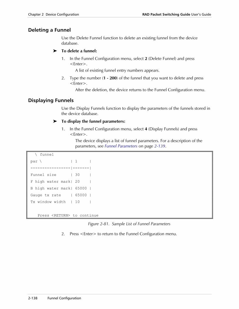
Chapter 2 Device Configuration RAD Packet Switching Guide User’s Guide
2-138 Funnel Configuration
Deleting a Funnel Use the Delete Funnel function to delete an existing funnel from the device database.
To delete a funnel:
1. In the Funnel Configuration menu, select 2 (Delete Funnel) and press <Enter>.
A list of existing funnel entry numbers appears.
2. Type the number (1 - 200) of the funnel that you want to delete and press <Enter>.
After the deletion, the device returns to the Funnel Configuration menu.
Displaying Funnels Use the Display Funnels function to display the parameters of the funnels stored in the device database.
To display the funnel parameters:
1. In the Funnel Configuration menu, select 4 (Display Funnels) and press <Enter>.
The device displays a list of funnel parameters. For a description of the parameters, see Funnel Parameters on page 2-139.
\ funnel
par \ | 1 |
-----------------|-------|
Funnel size | 30 |
F high water mark| 20 |
B high water mark| 65000 |
Gauge tx rate | 65000 |
Tx window width | 10 |
Press <RETURN> to continue
Figure 2-81. Sample List of Funnel Parameters
2. Press <Enter> to return to the Funnel Configuration menu.
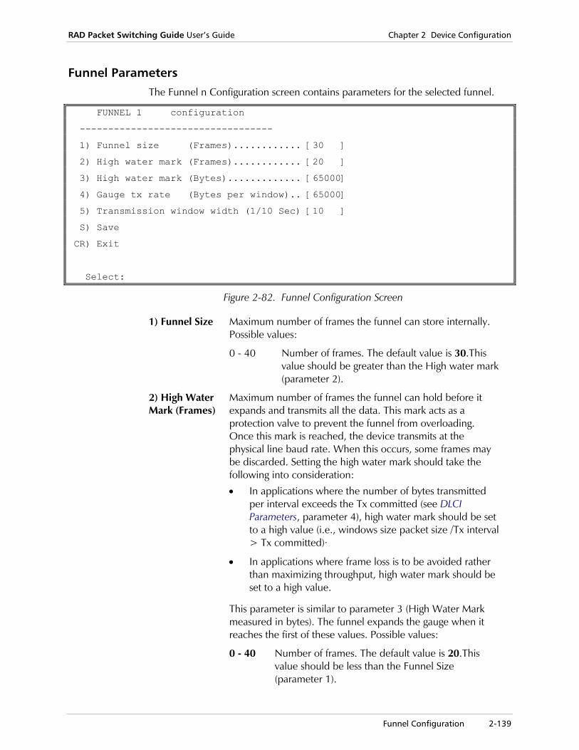
RAD Packet Switching Guide User’s Guide Chapter 2 Device Configuration
Funnel Configuration 2-139
Funnel Parameters The Funnel n Configuration screen contains parameters for the selected funnel.
FUNNEL 1 configuration
----------------------------------
1) Funnel size (Frames)............ [30 ]
2) High water mark (Frames)............ [20 ]
3) High water mark (Bytes)............. [65000]
4) Gauge tx rate (Bytes per window).. [65000]
5) Transmission window width (1/10 Sec) [10 ]
S) Save
CR) Exit
Select:
Figure 2-82. Funnel Configuration Screen
1) Funnel Size Maximum number of frames the funnel can store internally. Possible values:
0 - 40 Number of frames. The default value is 30.This value should be greater than the High water mark (parameter 2).
2) High Water Mark (Frames)
Maximum number of frames the funnel can hold before it expands and transmits all the data. This mark acts as a protection valve to prevent the funnel from overloading. Once this mark is reached, the device transmits at the physical line baud rate. When this occurs, some frames may be discarded. Setting the high water mark should take the following into consideration:
• In applications where the number of bytes transmitted per interval exceeds the Tx committed (see DLCI Parameters, parameter 4), high water mark should be set to a high value (i.e., windows size packet size /Tx interval > Tx committed)·
• In applications where frame loss is to be avoided rather than maximizing throughput, high water mark should be set to a high value.
This parameter is similar to parameter 3 (High Water Mark measured in bytes). The funnel expands the gauge when it reaches the first of these values. Possible values:
0 - 40 Number of frames. The default value is 20.This value should be less than the Funnel Size (parameter 1).

Chapter 2 Device Configuration RAD Packet Switching Guide User’s Guide
2-140 Funnel Configuration
3) High Water Mark (Bytes)
Maximum number of bytes the funnel can store before it expands and transmits all the data. This parameter is similar to parameter 2 (High Water Mark measured in frames). The funnel expands the gauge when it reaches the first of these values. Possible values:
0 - 65000 Number of bytes. The default value is 65000.
4) Gauge Tx Rate
Output data rate of the funnel. When the device detects Tx congestion, the funnel reduces the Tx rate to the Tx committed rate. If Tx congestion is still detected, Tx rate will be reduced to 3/4 of the Tx committed rate. If Tx congestion is still detected, Tx rate will be reduced to 1/2 of the Tx committed rate. If Tx congestion is still detected, Tx rate will be reduced to 1/4 of the Tx committed rate. Recommended values include the following:
• The Tx committed value defined for the DLCI using this funnel (see DLCI Parameters on page 2-53). This value may be used to prevent transmission from exceeding the Tx committed value.
• The Tx access defined for the DLCI using this funnel (see DLCI Parameters on page 2-53).
Possible values:
0 - 65000 Number of bytes per window. The default value is 65000.
Tx congestion is detected when 5 consecutive frames are received with the BECN bit set to on. Tx congestion is over when 5 consecutive frames are received with BECN bit set to off.
5) Transmission Window Width
Width of sliding time window, in which the transmission rate is measured. Recommended value is the Tx CIR interval defined for the funnels DLCI (see DLCI Parameters on page 2-53). Possible values:
0 - 10 Units of 1/10 seconds. The default value is 10.
Note

RAD Packet Switching Guide User’s Guide Chapter 2 Device Configuration
X.32 Support 2-141
2.11 X.32 Support
RAD packet switching devices V. 3.4 and higher support X.32 Rec. dialing facility. This enables the device to generate and receive X.25 calls over a PSTN (Public Switched Telephone Network) according to V25 BIS standards.
Modem
PSTN
RADPacketSwitch
Modem
X.25 Network
Figure 2-83. X.32 Support
In addition, the X.32 support provides protection facilities. These facilities control incoming communication from the PSTN to the X.25 network. The protection facility features two routines:
XID (Exchange Identification)
The Exchange ID (XID) is a code used to identify a DTE. If X.32 support is active, the device only accepts calls that have a correct XID. An XID code list with acceptable XIDs is entered to the device database. The device compares the XID of the incoming call requests and accepts the call only if its XID matches one of the XIDs defined on the list.
Dial-back The Dial-back function enables the device to reconfirm the validity of the incoming call. If Dial-back is active, the device disconnects the incoming call and recalls the calling DTE.
The calling DTE establishes communication only when generating a call request that has a valid XID and a correlating Calling address. A predefined Dial-back number list is entered to the device database. Each Dial back number is correlated to an XID. The device dials back the number correlating with the incoming XID. If the dial-back is successful, communication is established.
Chapter 2 Device Configuration RAD Packet Switching Guide User’s Guide
2-142 X.32 Support
Activating X.32 Support The X.32 support is defined per X.25 link. Activating the support requires the two following steps:
Creating an XID Table
The Exchange ID (XID) table defines the protection facilities (XIDs and Dial-back numbers) and dial-out parameters (Dial Out number and XID Out) used to control communication from and to the PSTN. The XID tables and their configurations are explained in the following paragraphs.
Activating X.32 Support on a specific X.25 link
This task requires the configuration of two X.25 link parameters in the X.25 Link n Configuration screen (see X.25 Link Parameters on page 2-35):
• Line Option (parameter 23)
• XID Number (parameter 25).
Line Option Enables the device to work with a dial up modem.
XID Number Enables the assignment of a pre configured XID table to the X.25 link. This parameter activates the assigned XID Table Communication definitions over the link.
If XID parameters are not necessary, setting only the Line Option parameter may activate X.32 support. In this case, no XID table is assigned to the link. The XID number parameter should be set to zero (0).
If X.32 support is active, the X.25 link complies with X.32 definitions.
XID Table Configuration From the XID Table Configuration menu, you can:
• Add a new XID table
• Update an existing XID table
• Delete an XID table
• Display an existing XID table.
Note

RAD Packet Switching Guide User’s Guide Chapter 2 Device Configuration
X.32 Support 2-143
To use the XID Table Configuration menu:
1. In the Configuration menu, select 11 (X.32) and press <Enter>. The XID Table Configuration menu appears.
XID table configuration ----------------------------------- 1) Add XID table 2) Delete XID table 3) Update XID table 4) Display XID tables CR) Exit Select:
Figure 2-84. XID Table Configuration Menu
2. Type the number of a function and press <Enter>. The appropriate menu appears.
3. To return to the Configuration menu, press <Enter> without selecting an option.
Adding an XID Table
Use the Add XID Table function to define a new XID table and determine its characteristics. To activate the XID facility, the XID table must be defined in the X.25 Link n Configuration screen (see X.25 Link Parameters on page 2-35).
To add an XID table:
1. In the XID Table Configuration menu, select 1 (Add XID Table) and press <Enter>.
A list of existing XID table numbers appears.
2. Type a number for the new XID table (1 - 200) and press <Enter>. The XID Table n Configuration screen appears. For a description of the parameters, see XID Table Parameters on page 2-145.
The XID Table n Configuration screen provides for the definition of up to 13 XIDs and 13 Dial-Back numbers.
3. To configure a specific parameter, type its number and press <Enter>. The device prompts you for the new parameter value.
4. Type a new parameter value and press <Enter>. The new value appears in the value column.
5. Type S and press <Enter> to save the new configuration.
To cancel the changes you made, exit without saving the new values.
6. To exit the XID Table n Configuration screen, press <Enter> without making any parameter selection.
Note
Note

Chapter 2 Device Configuration RAD Packet Switching Guide User’s Guide
2-144 X.32 Support
Updating the XID Table
Use the Update XID Table function to display and change the parameters of an existing XID table.
To update an XID table:
1. In the XID Table Configuration menu, select 3 (Update XID Table). A list of existing Call IDs appears.
2. Type the number of the XID table (1 - 200) you want to update and press <Enter>.
The XID Table n Configuration screen appears. The table number (n) is identified in the screen title.
3. Repeat steps 3 - 6 of the procedure in the section, Adding an XID Table on page 2-143.
Deleting an XID Table
Use the Delete XID Table function to delete an existing XID table.
To delete an XID table:
1. In the XID Table Configuration menu, select 2 (Delete XID Table) and press <Enter>.
A list of existing XID table numbers appears.
2. Type the number (1 - 200) of the XID table that you want to delete and press <Enter>.
After the deletion, the device returns to the XID Table Configuration menu.
Displaying XID Tables
Use the Display XID Tables function to display the parameters of an existing XID table.
To display an XID table:
1. In the XID Table Configuration menu, select 4 (Display XID Tables) and press <Enter>.
A list of existing XID table numbers appears.
2. Type the number of the XID table (1 - 200) you want to display and press <Enter>.
The XID Table Configuration screen appears, displaying the parameters for the selected XID table. For a description of the parameters, see XID Table Parameters on page 2-145.
3. Press <Enter> to return to the XID Table Configuration menu.

RAD Packet Switching Guide User’s Guide Chapter 2 Device Configuration
X.32 Support 2-145
XID Table Parameters The XID Table n Configuration screen contains the parameters for the selected XID table.
XID table 1 configuration
---------------------------------
XID Dial-back phone
-------------------------------------------------------
1) **************** | 14)
2) | 15)
3) | 16)
4) | 17)
5) | 18)
6) | 19)
7) | 20)
8) | 21)
9) | 22)
10) | 23)
11) | 24)
12) | 25)
13) | 26)
Outgoing XID Outgoing Phone number
-------------------------------------------------------
27) | 28)
enter: 1-28) Update parameters. S) save. CR) exit.
Figure 2-85. XID Table n Configuration Screen

Chapter 2 Device Configuration RAD Packet Switching Guide User’s Guide
2-146 X.32 Support
1) XID Alphanumeric XID code. The device will accept only calls that have one of the XID codes specified in this table. Possible values:
Up to 16 alphanumeric characters
(“A” - “Z”, “a” - “z”, “0” - “9”) underline (“_”) or asterisk (“*”). The asterisk stands for a “don’t care” character.
The default value is ****************.
To clear this parameter press <Space>.
2) Dial-back Phone
When the device receives the caller’s XID, it disconnects and dials the caller back, using the phone number entered in this field. This verifies the validity of the caller. This field corresponds to the XID on the same line (for example, XID 1/Dialback 14, XID 2/ Dialback 15, and so on).
Possible values: Up to 16 digits (“0” - “9”).
To disable the dial-back function, press <Space>.
3) Outgoing XID
XID of the device that is attached to outgoing calls. When the current XID table is configured to a specific link (in the X.25 Link n Configuration screen), all outgoing calls on that link will have this XID. Possible values:
Up to 16 alphanumeric characters
(“A” - “Z”, “a” - “z”, “0” - “9”) underline (“_”). To clear this parameter, press <Space>.
4) Outgoing Phone Number
Phone number for the device’s outgoing calls from the device. When the current XID table is configured to a specific link (in the X.25 Link n Configuration screen), all relevant outgoing calls will be dialed to this phone number.
Possible values: Up to 16 digits (“0” - “9”).
To disable the dial-back function, press <Space>.

RAD Packet Switching Guide User’s Guide Chapter 2 Device Configuration
Management Configuration 2-147
2.12 Management Configuration
The RAD packet switching devices support the configuration of network management and control tools:
SNMP The Simple Network Management Protocol (SNMP) is an important tool for network managers. SNMP enables the network manager to easily configure the network, using a convenient interactive environment. The manager can control all network entities that are SNMP-supported (such as hubs, routers, bridges, etc.). SNMP also supports real time statistics and event reports.
Event Report The Event Report feature enables the configuration of events and charging information reports.
Management Configuration Functions When you first enter the Management Configuration function, select the management tool that you want to configure, SNMP agent or the Event Report. After this selection, proceed from screen to screen to add or update the configuration, as required.
The Management Configuration menu provides a choice of the device’s management configuration features.
To use the Management Configuration menu:
1. In the Configuration menu, select 12 (Management) and press <Enter>. The Management Configuration menu appears.
Management Configuration
--------------------------
1) SNMP Agent
2) Event Report
CR) Exit
Select:
Figure 2-86. Management Configuration Menu
2. Select the management item that you want to configure (SNMP Agent or Event Report) and press <Enter>.
3. To exit the Management Configuration screen, press <Enter> without making a selection.
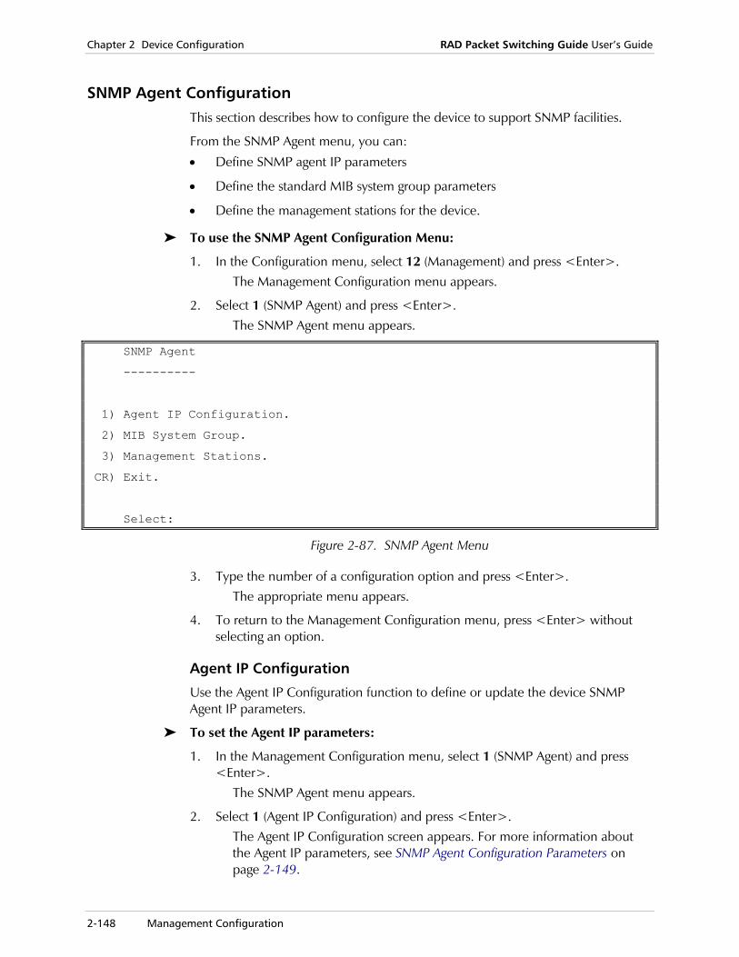
Chapter 2 Device Configuration RAD Packet Switching Guide User’s Guide
2-148 Management Configuration
SNMP Agent Configuration This section describes how to configure the device to support SNMP facilities.
From the SNMP Agent menu, you can:
• Define SNMP agent IP parameters
• Define the standard MIB system group parameters
• Define the management stations for the device.
To use the SNMP Agent Configuration Menu:
1. In the Configuration menu, select 12 (Management) and press <Enter>. The Management Configuration menu appears.
2. Select 1 (SNMP Agent) and press <Enter>. The SNMP Agent menu appears.
SNMP Agent
----------
1) Agent IP Configuration.
2) MIB System Group.
3) Management Stations.
CR) Exit.
Select:
Figure 2-87. SNMP Agent Menu
3. Type the number of a configuration option and press <Enter>. The appropriate menu appears.
4. To return to the Management Configuration menu, press <Enter> without selecting an option.
Agent IP Configuration
Use the Agent IP Configuration function to define or update the device SNMP Agent IP parameters.
To set the Agent IP parameters:
1. In the Management Configuration menu, select 1 (SNMP Agent) and press <Enter>.
The SNMP Agent menu appears.
2. Select 1 (Agent IP Configuration) and press <Enter>. The Agent IP Configuration screen appears. For more information about the Agent IP parameters, see SNMP Agent Configuration Parameters on page 2-149.

RAD Packet Switching Guide User’s Guide Chapter 2 Device Configuration
Management Configuration 2-149
3. To configure a specific parameter, type its number and press <Enter>. The device prompts you for the new parameter value.
4. Type a new parameter value and press <Enter>. The new value appears in the value column.
5. Type S and press <Enter> to save the new configuration.
To cancel the changes you made, exit without saving the new values.
6. To exit the Agent IP Configuration screen, press <Enter> without making any parameter selection.
SNMP Agent Configuration Parameters
The Agent IP Configuration screen contains the device’s IP parameters for SNMP management.
Agent IP Configuration
----------------------
1) IP Address ..................... [0.0.0.0]
2) Authentication Trap ............ [0 ]
3) IP Write Community ............. [ ]
4) IP Read Community .............. [public]
5) IP Trap Community .............. [ ]
S) Save.
CR) Exit.
Select:
Figure 2-88. Agent IP Configuration Screen
1) IP Address IP address of the device, through which the SNMP Agent operates. Possible values:
X.X.X.X Each X indicates a number in the range 0 - 255. For information about IP addressing, see IP Addressing on page 2-166.
2) Authentication Trap
Enables or disables the community authentication check. When active, the device checks all SNMP request communities and reports requests received with illegal community strings. Any community violation is reported to all device management stations. The authentication trap report includes information concerning when and where the authentication violation occurred and specifies the violating community. Possible values:
0 Disable Authentication Trap (default).
1 Enable Authentication Trap.
Note
Chapter 2 Device Configuration RAD Packet Switching Guide User’s Guide
2-150 Management Configuration
3) IP Write Community
Text string required in order to edit configurations in the device. Only users that have this Write Community may write to the device through the network management station (NMS). Possible values: Up to 20 characters.
4) IP Read Community
Text string required in order to receive information from the device. Only users that have this Read Community may read from the device through the network management station (NMS). Possible values: Up to 20 characters. The default value is Public.
5) IP Trap Community
Text string required in order to receive information about traps from the device. This parameter is used to select and reduce the amount of trap information entering the management station. Possible values: Up to 20 characters.
MIB System Group Configuration
Use the MIB System Group function to define the characteristics of the standard Management Information Base (MIB) system group.
To define the MIB System Group Parameters:
1. In the Management Configuration menu, select 1 (SNMP Agent) and press <Enter>.
The SNMP Agent menu appears.
2. Select 2 (MIB System Group) and press <Enter>. The MIB System Group Configuration screen appears. For more information about the Agent IP parameters, see MIB System Group Configuration on page 2-150.
3. To configure a specific parameter, type its number and press <Enter>. The device prompts you for the new parameter value.
4. Type a new parameter value and press <Enter>. The new value appears in the value column.
5. Type S and press <Enter> to save the new configuration.
To cancel the changes you made, exit without saving the new values.
6. To exit the MIB System Group Configuration screen, press <Enter> without making any parameter selection.
Note
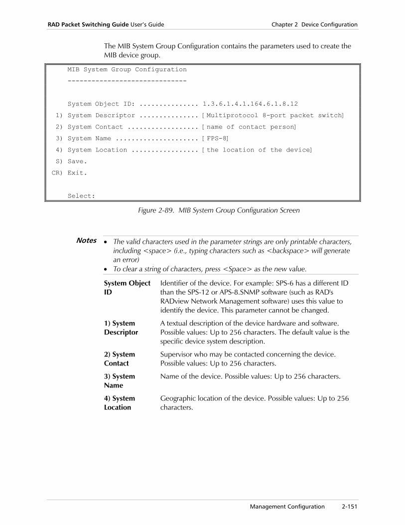
RAD Packet Switching Guide User’s Guide Chapter 2 Device Configuration
Management Configuration 2-151
The MIB System Group Configuration contains the parameters used to create the MIB device group.
MIB System Group Configuration
------------------------------
System Object ID: ............... 1.3.6.1.4.1.164.6.1.8.12
1) System Descriptor ............... [Multiprotocol 8-port packet switch]
2) System Contact .................. [name of contact person]
3) System Name ..................... [FPS-8]
4) System Location ................. [the location of the device]
S) Save.
CR) Exit.
Select:
Figure 2-89. MIB System Group Configuration Screen
• The valid characters used in the parameter strings are only printable characters, including <space> (i.e., typing characters such as <backspace> will generate an error)
• To clear a string of characters, press <Space> as the new value.
System Object ID
Identifier of the device. For example: SPS-6 has a different ID than the SPS-12 or APS-8.SNMP software (such as RAD's RADview Network Management software) uses this value to identify the device. This parameter cannot be changed.
1) System Descriptor
A textual description of the device hardware and software. Possible values: Up to 256 characters. The default value is the specific device system description.
2) System Contact
Supervisor who may be contacted concerning the device. Possible values: Up to 256 characters.
3) System Name
Name of the device. Possible values: Up to 256 characters.
4) System Location
Geographic location of the device. Possible values: Up to 256 characters.
Notes

Chapter 2 Device Configuration RAD Packet Switching Guide User’s Guide
2-152 Management Configuration
Management Station Configuration
The RAD packet switching devices support communication with up to five management stations.
From the Management Station Configuration menu, you can select one of the following management station configuration activities:
• Add a new management station
• Update an existing management station
• Delete a management station
• Display the management stations parameters.
To use the Management Station Configuration menu:
1. In the Management Configuration menu, select 1 (SNMP Agent) and press <Enter>.
The SNMP Agent menu appears.
2. Select 3 (Management Stations) and press <Enter>. The Management Station Configuration screen appears.
Management Station Configuration -------------------------------- 1) Add Management Station. 2) Delete Management Station. 3) Update Management Station. 4) Display Management Stations. CR) Exit. Select:
Figure 2-90. Management Station Configuration Menu
3. Type the number of a function and press <Enter>. The appropriate menu appears.
4. To return to the SNMP Agent menu, press <Enter> without selecting an option.
Use the Add Management Station function to define a new management station and select its characteristics. The device supports up to five management stations.
To add a management station:
1. In the Management Configuration menu, select 1 (SNMP Agent) and press <Enter>.
The SNMP Agent menu appears.
2. Select 3 (Management Stations) and press <Enter>. The Management Station Configuration screen appears.
RAD Packet Switching Guide User’s Guide Chapter 2 Device Configuration
Management Configuration 2-153
3. Select 1 (Add Management Station) and press <Enter>. A list of existing management stations appears.
4. Type an entry number for the new management station (1 - 5) and press <Enter>. The Management Station n Configuration screen appears. For a description of the parameters, see Management Station Parameters on page 2-155.
5. To configure a specific parameter, type its number and press <Enter>. The device prompts you for the new parameter value.
6. Type a new parameter value and press <Enter>. The new value appears in the value column.
7. Type S and press <Enter> to save the new configuration.
To cancel the changes you made, exit without saving the new values.
8. To exit the Management Station n Configuration screen, press <Enter> without making any parameter selection.
Updating a Management Station
Use the Update Management Station function to display and change the parameters of an existing management station.
To update a management station:
1. In the Management Configuration menu, select 1 (SNMP Agent) and press <Enter>.
The SNMP Agent menu appears.
2. Select 3 (Management Stations) and press <Enter>. The Management Station Configuration screen appears.
3. Select 3 (Update Management Station) and press <Enter>. A list of existing management stations appears.
4. Type the entry number of the management station (1 - 5) you want to update and press <Enter>.
The Management Station n Configuration screen appears. The management station number (n) is identified in the screen title.
5. Repeat steps 5 - 8 of the previous procedure.
Deleting a Management Station
Use the Delete Management Station function to delete an existing management station from the list.
To delete a management station:
1. In the Management Configuration menu, select 1 (SNMP Agent) and press <Enter>.
The SNMP Agent menu appears.
Note

Chapter 2 Device Configuration RAD Packet Switching Guide User’s Guide
2-154 Management Configuration
2. Select 3 (Management Stations) and press <Enter>. The Management Station Configuration screen appears.
3. Select 2 (Delete Management Station) and press <Enter>. A list of existing management stations appears.
4. Type the entry number (1 - 5) of the management station that you want to delete and press <Enter>.
After the deletion, the device returns to the Management Station Configuration menu.
Displaying Management Station Parameters
Use the Display Management Station function to display the parameters of a selected management station.
To display a management station:
1. In the Management Configuration menu, select 1 (SNMP Agent) and press <Enter>.
The SNMP Agent menu appears.
2. Select 3 (Management Stations) and press <Enter>. The Management Station Configuration screen appears.
3. Select 4 (Display Management Station) and press <Enter>. The device displays a list of management stations and indicates the types of traps each station can receive. If necessary, press <Enter> to continue to another screen. To show a specific range of entries, type the lowest entry number, a colon, and the highest entry number (for example, 2:4).
----+---------------+--------------+---+---+---+---+---+---+---+---+---+---+
Id.| IP Address | Trap Options | 1 | 2 | 4 | 8 | 16| 32| 64|128|256|512|
----+---------------+--------------+---+---+---+---+---+---+---+---+---+---+
1 | 192.20.168.2 | 0 | | | | | | | | | | |
Trap Options
===============================================================
0 - No Traps would be reported 32 - frDLCIStatusChange.
1 - Link Down. 64 - coldStart.
2 - Link Up. 128 - linkProtocolChange.
4 - rtsChange. 256 - enrollmentPS.
8 - reset X.25. 512 - ledStatusChange.
16 - restart X.25.
Press <CR> to Continue, NN:NN for range display, <Q> to QUIT
Figure 2-91. Sample Management Station List
4. Type Q to return to the Management Station Configuration menu.

RAD Packet Switching Guide User’s Guide Chapter 2 Device Configuration
Management Configuration 2-155
Management Station Parameters
The Management Station n Configuration screen contains the management station’s IP address and indications of the types of traps that it receives.
Management Station 1 Configuration
--------------------------------------
1) Management station IP Address ............ [0.0.0.0]
2) Management station Trap Options .......... [0 ]
S) Save.
CR) Exit.
Select:
Figure 2-92. Management Station Configuration Screen
1) Management Station IP
IP address of the selected management station. Possible values:
X.X.X.X Each X indicates a number in the range 0 - 255. For information about IP addressing, see IP Routing on page 2-166.
2) Management Station Trap Options
Types of events that will be reported to the management station, if one of the specified events occurs. Possible values:
0 No traps reported (default)
1 Link Down
2 Link Up
4 RTS Change
8 Reset X.25
16 Restart X.25
32 FR DLCI Status Change
64 Cold Start
128 Link Protocol Change
256 Enrollment PS
512 LED Status Change
xxx (Any combination of the above values)
This parameter is not related to the Community Authentication Trap facility.
Note

Chapter 2 Device Configuration RAD Packet Switching Guide User’s Guide
2-156 Management Configuration
Event Report Configuration Use the Event Report Configuration screen to define the parameters for operating the device’s Event Report facility.
The Event Report Configuration menu enables the configuration of Event and Charging information reports. This does not replace or affect the Channel Charging Information.
The device can generate the information to one or two different locations, depending on the configuration. This function can be used to establish a network supervising function (for example, all reports may be sent to a supervisor terminal, printer, etc.).
The device also provides a Condensed Mode option, for presenting the information in an abbreviated fashion.
To define the Event Report parameters:
1. In the Configuration menu, select 12 (Management) and press <Enter>. The Management Configuration menu appears.
2. Select 2 (Event Report) and press <Enter>. The Event Report Configuration screen appears.
3. To configure a specific parameter, type its number and press <Enter>. The device prompts you for the new parameter value.
4. Type a new parameter value and press <Enter>. The new value appears in the value column.
5. Type S and press <Enter> to save the new configuration.
To cancel the changes you made, exit without saving the new values.
6. To exit the Event Report Configuration screen, press <Enter> without making any parameter selection.
Note

RAD Packet Switching Guide User’s Guide Chapter 2 Device Configuration
Management Configuration 2-157
Event Report Parameters
The Event Report parameters determine report characteristics and the addresses these reports are generated to as follows:
• Event Report characteristics generated to the first address (parameters 1 - 3)
• Event Report characteristics generated to the second address (parameters 4 - 6)
• General Event Report Configuration parameters (parameters 7 - 9).
Event Report Configuration ---------------------------- / 1) Event report port 1 address .......... [ ] Port 1 < 2) Event report port 1 mask ............. [0 ] \ 3) Event report port 1 period ........... [0 ] / 4) Event report port 2 address .......... [ ] Port 2 < 5) Event report port 2 mask ............. [0 ] \ 6) Event report port 2 period ............[0 ] 7) Event Report Retry Count ..............[5 ] 8) Event Report Retry Delay ..............[1 ] 9) Event Report Options ..................[0 ] S) Save CR) Exit Select:
Figure 2-93. Event Report Configuration Screen
1) Event Report Port 1 Address
Address to which the device generates an Event Report. Possible values:
up to 15 digits (“0” - “9”)
X.25 address or local Async address.
2) Event Report Port 1 Mask
Determines when the device sends event reports to the port 1 address. Possible values:
0 No event reports sent.
1 Send report when SYNC status has changed.
2 Send report when RTS status has changed.
4 Send report at power ON (reset).
8 Send charging information report at CLR.
X Any combination of the above values.

Chapter 2 Device Configuration RAD Packet Switching Guide User’s Guide
2-158 Management Configuration
3) Event Report Port 1 Period
Interval at which the device sends a status screen to the port 1 address. Possible values:
0 No periodic reports sent.
1 - 255 Number of minutes.
4) Event Report Port 2 Address
Same as parameter 1, except for an alternate port address.
5) Event Report Port 2 Mask
Same as parameter 2, except for an alternate port address.
6) Event Report Port 2 Period
Same as parameter 3, except for an alternate port address.
The device normally generates the report to both addresses (port 1 and port 2 defined by parameters 1 and 4). You can change this by setting parameter 9 (Event Report Options) to Alternate Mode (1).
7) Event Report Retry Count
Maximum number of retries for sending the Event Report to the destination addresses (ports 1 and 2) in case of connection problems. Possible values:
0 No retries.
1 - 255 Number of retries. The default value is 5.
8) Event Report Retry Delay
Time interval between retries. Possible values:
1 - 255 Number of minutes. The default value is 1.
9) Event Report Options
Options that define the mode and format of the event reports. Possible values:
0 No options. Reports are generated to both ports 1 and 2 in normal format (not condensed mode) (default).
1 Alternate Mode. Port 2 definitions are used as the secondary destination. Reports are first sent to the port 1 address. If connection fails (after the retries), the device sends the report to the port 2 address.
If this value is selected, port 2 Mask and Time period parameter (number 5,6), are not used. In case of connection failure, the report is sent to the port 2 address with the Mask and Time that was defined for port 1.
2 Condensed Format. Reports are displayed in a concise abbreviated format.
3 Alternate Mode and Condensed Format are enabled.
Note
Note
RAD Packet Switching Guide User’s Guide Chapter 2 Device Configuration
Management Configuration 2-159
Condensed Mode
The condensed report begins with a Semicolon (;) followed by the Event Report Mask (as defined by parameters 2 or 4). The report then displays the requested information using the abbreviations listed below.
BR - Bytes Received
BT - Bytes Transmitted
CH - Channel number
CU - CUG number
DA - Destination Address
DN - Throughput class negotiation
EL - Elapsed time
FS - fast select
ID - Device ID
LC – LCN
LN - link number
NU - NUI
PN - Packet size negotiation
PR - Packets Received
PT - Packets Transmitted
RC - Reverse Charge
RN - Report Number
RT - RTS status
SA - Source Address
SR - Segments Received
ST - Segments Transmitted
SY - SYNC status
TE - Time End
TS - Time Start
WN - Window Size Negotiation
The following example presents a billing information Event Report in condensed mode, generated after a call is cleared.
Event Report parameter values:
Mask 8 Charging information at CLR.
Time period 0 Not relevant for this example.
Event Report options 2 Condensed format
Sample Report:
;8,RN 5,ID TELAVIV-101,CH 1,TS 960501 08:30:12,TE 960501 09:05:33,PT 8,PR 4,BT 121,BR 195,ST 8,SR 4,SA ,DA 101,NU ID_1234,LN 6,LC 1,RC 0,FS 1,CU ——,PN 1,WN 1,DN 0
For example, the first few Report arguments specify the following:
;8 Beginning of report (;) and report mask number (8).
RN 5 Report number 5.
ID TELAVIV-101 Device ID
CH 1 Channel number 1 (Report source).
TS 960501 08:30:12 The call transmission began on the first of May, 1996, at 8:30 AM (and 12 seconds).
Chapter 2 Device Configuration RAD Packet Switching Guide User’s Guide
2-160 Multi-Cast Configuration
2.13 Multi-Cast Configuration
Introduction The Multi-Cast feature enables simultaneous transmission to several X.25 or Frame Relay destinations.
Multi-Cast is configured by assigning a mutual address, or MCG (Multi-Cast Group) to several users. If a Call Request packet with the MCG address is received, it is distributed to all the group members. Calls are established and data transmitted to every member simultaneously.
The Multi-Cast feature does not support error correction. If the device uses Multi-Cast to broadcast over several links simultaneously, flow control is not available over these links. This prevents failure on a single or several links from stopping or holding back transmission to all other links. In this case no failure message is generated. The broadcasting user and the destination user are not notified when this occurs.
Only if all the MCG destination calls are cleared will the broadcasting user receive a clear message.
Multi-Casting is a switch feature of the device. The device can only apply Multi-Casting to packets that are received from Sync links. Multi-Casting under PAD settings (i.e. Multi-Casting from a terminal connected to the device via an Async link/channel) may be achieved using a special configuration. For more details, see Multi-Casting Under PAD Configuration on page 2-161.
Up to 10 Multi-Cast Groups, each containing up to 20 destination addresses may be defined.
The MCG members’ addresses have to be uniquely configured. Destination addresses in the MCG cannot have a “wild card.”
Every address of the MCG members has to be defined in the device Routing Table in the usual fashion. (“Don’t care” digits may be used when configuring addresses in the Routing Table). For more information, see Routing Table Configuration on page 2-128.
A Call Request packet bearing the MCG address (as its calling address) that is received on a Sync link is Multi-Casted. This occurs even if the MCG address is configured into the Routing Table. The Multi-Cast procedure has priority over the Routing Table definitions.
If a Call Request packet bearing the MCG address (as its calling address) is received on an Async link/channel the Multi-Casting procedure is not generated. The device refers to the call under standard X.25 regulations. If the MCG address is configured into the Routing Table, the packet is forwarded to the link defined by the Routing Table entry.
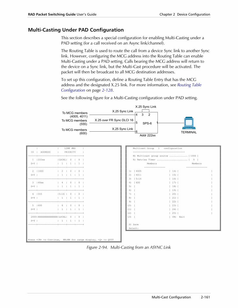
RAD Packet Switching Guide User’s Guide Chapter 2 Device Configuration
Multi-Cast Configuration 2-161
Multi-Casting Under PAD Configuration This section describes a special configuration for enabling Multi-Casting under a PAD setting (for a call received on an Async link/channel).
The Routing Table is used to route the call from a device Sync link to another Sync link. However, configuring the MCG address into the Routing Table can enable Multi-Casting under a PAD setting. Calls bearing the MCG address will return to the device on a Sync link, but the Multi-Cast procedure will be activated. The packet will then be broadcast to all MCG destination addresses.
To set up this configuration, define a Routing Table Entry that has the MCG address and the designated X.25 link. For more information, see Routing Table Configuration on page 2-128.
See the following figure for a Multi-Casting configuration under PAD setting.
TERMINAL
SPS-6
X.25 Sync Link
X.25 Sync Link
X.25 Sync Link
To MCG members(4005, 4011)
To MCG members(555)
To MCG members(600)
X.25 over FR Sync DLCI 16
Addr 222xx
1
234
5
6
| | LINK #NO |
ID | ADDRESS | PRIORITY |
------+--------------+-----+-----+-----+
1 |222xx |LOCAL| 0 | 0 |
S=Y | | 1 | 1 | 1 |
------+--------------+-----+-----+-----+
2 |1000 | 2 | 0 | 0 |
S=Y | | 1 | 1 | 1 |
------+--------------+-----+-----+-----+
3 |40xx | 4 | 0 | 0 |
S=Y | | 1 | 1 | 1 |
------+--------------+-----+-----+-----+
4 |555 |5:16 | 0 | 0 |
S=Y | | 1 | 1 | 1 |
------+--------------+-----+-----+-----+
5 |600 | 6 | 0 | 0 |
S=Y | | 1 | 1 | 1 |
------+--------------+-----+-----+-----+
2000|XXXXXXXXXXXXXX|LOCAL| 0 | 0 |
S=Y | | 1 | 1 | 1 |
------+--------------+-----+-----+-----+
Press <CR> to Continue, NN:NN for range display, <Q> to QUIT
Multicast Group 1 configuration
-------------------------------------
M) Multicast group source ............. [1000 ]
R) Retries Timer ...................... [ 5 ]
Members Members
--------------- ---------------
1) [4005 ] 14) [ ]
2) [4011 ] 15) [ ]
3) [5:16 ] 16) [ ]
4) [600 ] 17) [ ]
5) [ ] 18) [ ]
6) [ ] 19) [ ]
7) [ ] 20) [ ]
8) [ ] 21) [ ]
9) [ ] 22) [ ]
10) [ ] 23) [ ]
11) [ ] 24) [ ]
12) [ ] 25) [ ]
13) [ ] CR) Exit
S) Save
Select:
Figure 2-94. Multi-Casting from an ASYNC Link
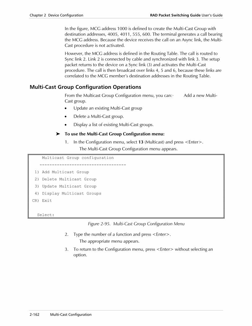
Chapter 2 Device Configuration RAD Packet Switching Guide User’s Guide
2-162 Multi-Cast Configuration
In the figure, MCG address 1000 is defined to create the Multi-Cast Group with destination addresses, 4005, 4011, 555, 600. The terminal generates a call bearing the MCG address. Because the device receives the call on an Async link, the Multi-Cast procedure is not activated.
However, the MCG address is defined in the Routing Table. The call is routed to Sync link 2. Link 2 is connected by cable and synchronized with link 3. The setup packet returns to the device on a Sync link (3) and activates the Multi-Cast procedure. The call is then broadcast over links 4, 5 and 6, because these links are correlated to the MCG member’s destination addresses in the Routing Table.
Multi-Cast Group Configuration Operations From the Multicast Group Configuration menu, you can:· Add a new Multi-Cast group.
• Update an existing Multi-Cast group
• Delete a Multi-Cast group.
• Display a list of existing Multi-Cast groups.
To use the Multi-Cast Group Configuration menu:
1. In the Configuration menu, select 13 (Multicast) and press <Enter>. The Multi-Cast Group Configuration menu appears.
Multicast Group configuration
-----------------------------------
1) Add Multicast Group
2) Delete Multicast Group
3) Update Multicast Group
4) Display Multicast Groups
CR) Exit
Select:
Figure 2-95. Multi-Cast Group Configuration Menu
2. Type the number of a function and press <Enter>. The appropriate menu appears.
3. To return to the Configuration menu, press <Enter> without selecting an option.
RAD Packet Switching Guide User’s Guide Chapter 2 Device Configuration
Multi-Cast Configuration 2-163
Adding a Multi-Cast Group
Use the Add Multi-Cast Group function to define a new Multi-Cast Group (MCG) and select its characteristics.
To add an MCG:
1. In the Multi-Cast Group Configuration menu, select 1 (Add Multi Cast Group) and press <Enter>.
A list of existing MCGs appears.
2. Type a number for the new MCG (1 - 10) and press <Enter>. The Multi-Cast Group n Configuration screen appears. For a description of the parameters, see MCG Parameters on page 2-164.
3. To configure a specific parameter, type its number and press <Enter>. The device prompts you for the new parameter value.
4. Type a new parameter value and press <Enter>. The new value appears in the value column.
5. Type S and press <Enter> to save the new configuration.
To cancel the changes you made, exit without saving the new values.
6. To add another MCG, repeat steps 2 to 5.
7. To exit the Call ID n Configuration screen, press <Enter> without making any parameter selection.
Updating an MCG
Use the Update Multi-Cast Group function to display and change the parameters of an existing MCG.
To update an MCG:
1. In the Multi-Cast Group Configuration menu, select 3 (Update Multi Cast Group) and press <Enter>.
A list of existing MCGs appears.
2. Type the number of the MCG (1 - 10) you want to update and press <Enter>.
The Multi-Cast Group n Configuration screen appears. The MCG number (n) is identified in the screen title.
3. Repeat steps 3 - 7 of the procedure in the section Adding a Multi-Cast Group on page 2-163.
Note

Chapter 2 Device Configuration RAD Packet Switching Guide User’s Guide
2-164 Multi-Cast Configuration
Deleting an MCG
Use the Delete Multi-Cast Group function to delete an existing MCG.
To delete an MCG:
1. In the Multi-Cast Group Configuration menu, select 2 (Delete Multi Cast Group) and press <Enter>.
A list of existing MCG numbers appears.
2. Type the number (1 - 10) of the MCG that you want to delete and press <Enter>.
After the deletion, the device returns to the Multi-Cast Group Configuration menu.
Displaying MCGs
The Display Multi-Cast Groups function is not yet implemented.
To see the parameters of a specific MCG, use the Update Multi-Cast Group function.
MCG Parameters The Multi-Cast Group n Configuration screen contains the parameters for the selected MCG.
Multicast Group 1 configuration ------------------------------------- M) Multicast group source ............. [ ] R) Retries Timer ...................... [ 5 ] Members Members --------------- --------------- 1) [ ] 14) [ ] 2) [ ] 15) [ ] 3) [ ] 16) [ ] 4) [ ] 17) [ ] 5) [ ] 18) [ ] 6) [ ] 19) [ ] 7) [ ] 20) [ ] 8) [ ] 21) [ ] 9) [ ] 22) [ ] 10) [ ] 23) [ ] 11) [ ] 24) [ ] 12) [ ] 25) [ ] 13) [ ] CR) Exit S) Save Select:
Figure 2-96. Multi-Cast Group n Configuration Screen

RAD Packet Switching Guide User’s Guide Chapter 2 Device Configuration
Multi-Cast Configuration 2-165
M) Multi-Cast Group Source
MCG address. This is the mutual address used to generate data distribution to all MCG members. The MCG members addresses appear in parameters 1 to 25.Possible values:
Up to 15 digits (“0” - “9”)
Valid X.25 address.
Port: DLCI Valid Frame Relay link and DLCI number.
Press <Space> Remove the previous value without replacing it.
R) Retries Timer
Time interval in which the device tries to open a call to each MCG address. The device checks each member of the MCG in every retry. If a call is not open yet, the device will attempt to open one. Possible values:
0 - 255 Number of minutes. The default value is 5.
1 - 25) Members
MCG member X.25 or FR address. The device uses this address to route data to the MCG member. This MCG address must be defined in the Routing Table as well. Select the appropriate member number by typing its entry number (1 - 25). Possible values:
Up to 15 digits (“0” - “9”)
Valid X.25 address.
Port: DLCI Broadcast Multi-Cast on a valid Frame Relay link and DLCI number. The device sends data from the source DLCI to all Broadcast members of the group.
Port: DLCI, Port: DLCI
One-way Multi-Cast on a valid Frame Relay link and DLCI number. The device sends data from the source DLCI to an MCG member, which sends the data on to another DLCI. The MCG member cannot send data back to the source DLCI.
m, Port: DLCI Two-way Multi-Cast on a valid Frame Relay link and DLCI number. The device and other MCG members of the same group may send/receive data to/from each other.

Chapter 2 Device Configuration RAD Packet Switching Guide User’s Guide
2-166 IP Routing
2.14 IP Routing
Internet Protocol (IP) is part of the Transmission Control Protocol/Internet Protocol (TCP/IP) protocol suite. The TCP/IP protocols are the official protocols for the Internet.
RAD Packet Switching devices V.3.4 and higher support multi-protocol IP encapsulation. This enables IP datagrams transmission over one of the device supported protocol networks. IP may be encapsulated over X.25 PVC and SVC, Frame Relay, SLIP link, HDLC, Ethernet or PPP. In addition, IP serves the local SNMP agent.
Using the IP Routing function, you define the routing of the IP datagrams using the datagrams’ IP Address.
IP Addressing An IP Address is a 32-bit sequence. The address is separated into four bytes, each indicated by a number between 0 and 255. The four numbers are strung together, separated by dots, to represent the complete IP Address.
For example, the 32-bit IP address:
11000000 00000010 10000000 00010101
is represented as :192.2.128.21
• 192 is the decimal value of the high byte 11000000
• 2 is the decimal value of the next lower byte 00000010
• 128 is the decimal value of the next lower byte 10000000
• 21 is the decimal value of the lowest byte 00010101
Address Masking Address Masking enables the reference to several addresses that share several identical bits, in one address entry.
The Address Mask is a 32-bit sequence. The Mask is represented in the decimal dot format identical to the one used to represent the IP Address. The Mask is related to an IP Address. The 1 bits of the mask determine the significant bits of the IP Address, and the 0 bits indicate the “don’t care” bits.
Examples of Address Masking
1) Consider the IP Address:
192.2.128.21 (11000000 00000010 10000000 00010101)
which appears with the mask:
255.255.255.255 (11111111 11111111 11111111 11111111)
All mask bits are 1. Therefore, only the specific address (192.2.128.21) is referred.
RAD Packet Switching Guide User’s Guide Chapter 2 Device Configuration
IP Routing 2-167
2) Consider the IP Address:
192.2.128.21 (11000000 00000010 10000000 00010101)
which appears with the mask:
255.255.255.0 (11111111 11111111 11111111 00000000)
The lowest byte of the mask is all 0. All addresses ranging from 192.2.128.0 to 192.2.128.255 will be referred.
Static IP Routing The Static Routing procedure uses an IP Routing table. The IP Routing table includes IP Routing entries that correlate IP Addresses (defined by the address and its mask) with logical destination interfaces. When the device receives an IP datagram, it searches the IP Routing table. If the device matches the datagrams destination address with the addresses defined in one of the IP Routing table entries, it encapsulates the datagram, and forwards the datagram to the interface specified in that entry.
If an interface referred to by an IP Routing entry is not synchronized, the device does not match the destination address with that entry, even if the addresses of the entry and destination addresses match. Instead, the device continues searching for a matching address through the remaining IP Routing entries.
If the mask is used to define a range of addresses, several entries may match the same destination address. If this occurs, the address that spans over a smaller range of addresses.
For example:
If the destination address is 192.2.128.21 and the two following entries exist in the IP Routing table:
Entry 1 IP Address: 192.2.128.21 IP mask 255.255.255.255
Entry 2 IP Address: 192.2.128.30 IP mask 255.255.255.0
Both entries match the destination address. However, entry 1 is used because it defines one specific address, while entry 2 spans over 256 addresses.
If IP is encapsulated over X.25 SVC, the X.25 Routing Table is also used. The device uses the IP Routing information to encapsulate the datagram over the X.25 frame. The X.25 frame is then transmitted using the X.25 Routing Table. Therefore, you must configure the X.25 Routing Table if the protocol is IP encapsulation over X.25 SVC. For more information about defining X.25 Routing tables, see Routing Table Configuration on page 2-128.
Note
Note
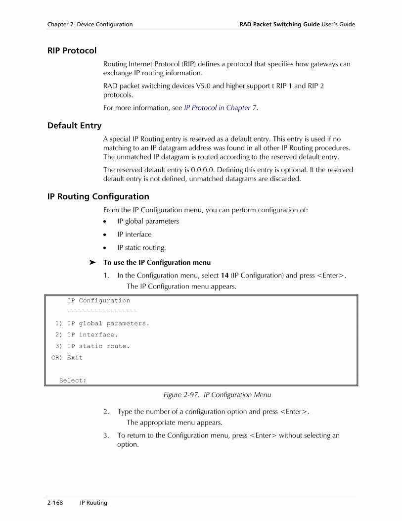
Chapter 2 Device Configuration RAD Packet Switching Guide User’s Guide
2-168 IP Routing
RIP Protocol Routing Internet Protocol (RIP) defines a protocol that specifies how gateways can exchange IP routing information.
RAD packet switching devices V5.0 and higher support t RIP 1 and RIP 2 protocols.
For more information, see IP Protocol in Chapter 7.
Default Entry A special IP Routing entry is reserved as a default entry. This entry is used if no matching to an IP datagram address was found in all other IP Routing procedures. The unmatched IP datagram is routed according to the reserved default entry.
The reserved default entry is 0.0.0.0. Defining this entry is optional. If the reserved default entry is not defined, unmatched datagrams are discarded.
IP Routing Configuration From the IP Configuration menu, you can perform configuration of:
• IP global parameters
• IP interface
• IP static routing.
To use the IP Configuration menu
1. In the Configuration menu, select 14 (IP Configuration) and press <Enter>. The IP Configuration menu appears.
IP Configuration
------------------
1) IP global parameters.
2) IP interface.
3) IP static route.
CR) Exit
Select:
Figure 2-97. IP Configuration Menu
2. Type the number of a configuration option and press <Enter>. The appropriate menu appears.
3. To return to the Configuration menu, press <Enter> without selecting an option.
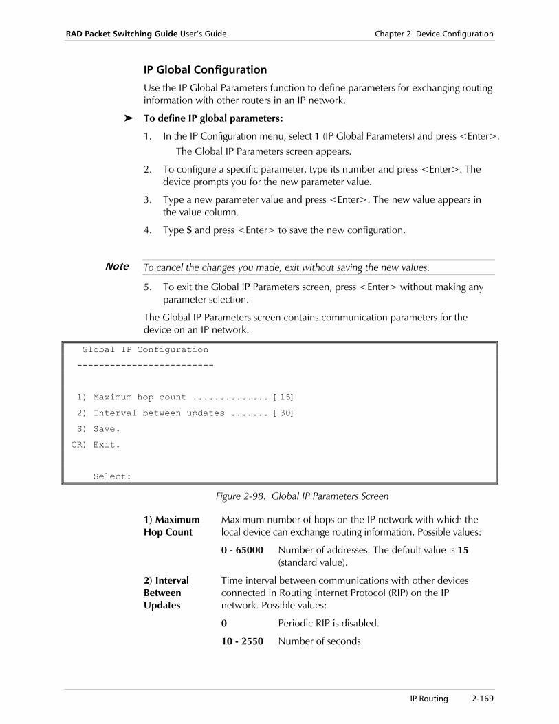
RAD Packet Switching Guide User’s Guide Chapter 2 Device Configuration
IP Routing 2-169
IP Global Configuration
Use the IP Global Parameters function to define parameters for exchanging routing information with other routers in an IP network.
To define IP global parameters:
1. In the IP Configuration menu, select 1 (IP Global Parameters) and press <Enter>. The Global IP Parameters screen appears.
2. To configure a specific parameter, type its number and press <Enter>. The device prompts you for the new parameter value.
3. Type a new parameter value and press <Enter>. The new value appears in the value column.
4. Type S and press <Enter> to save the new configuration.
To cancel the changes you made, exit without saving the new values.
5. To exit the Global IP Parameters screen, press <Enter> without making any parameter selection.
The Global IP Parameters screen contains communication parameters for the device on an IP network.
Global IP Configuration
-------------------------
1) Maximum hop count .............. [15]
2) Interval between updates ....... [30]
S) Save.
CR) Exit.
Select:
Figure 2-98. Global IP Parameters Screen
1) Maximum Hop Count
Maximum number of hops on the IP network with which the local device can exchange routing information. Possible values:
0 - 65000 Number of addresses. The default value is 15 (standard value).
2) Interval Between Updates
Time interval between communications with other devices connected in Routing Internet Protocol (RIP) on the IP network. Possible values:
0 Periodic RIP is disabled.
10 - 2550 Number of seconds.
Note
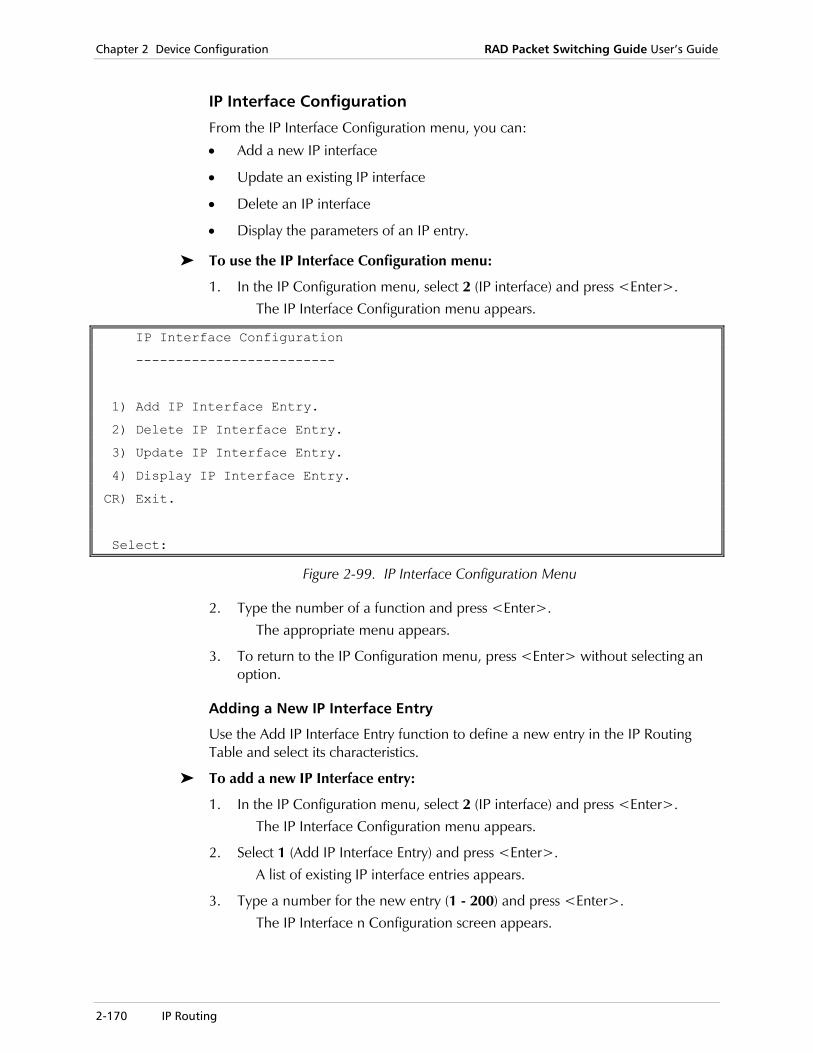
Chapter 2 Device Configuration RAD Packet Switching Guide User’s Guide
2-170 IP Routing
IP Interface Configuration
From the IP Interface Configuration menu, you can:
• Add a new IP interface
• Update an existing IP interface
• Delete an IP interface
• Display the parameters of an IP entry.
To use the IP Interface Configuration menu:
1. In the IP Configuration menu, select 2 (IP interface) and press <Enter>. The IP Interface Configuration menu appears.
IP Interface Configuration
-------------------------
1) Add IP Interface Entry.
2) Delete IP Interface Entry.
3) Update IP Interface Entry.
4) Display IP Interface Entry.
CR) Exit.
Select:
Figure 2-99. IP Interface Configuration Menu
2. Type the number of a function and press <Enter>. The appropriate menu appears.
3. To return to the IP Configuration menu, press <Enter> without selecting an option.
Adding a New IP Interface Entry
Use the Add IP Interface Entry function to define a new entry in the IP Routing Table and select its characteristics.
To add a new IP Interface entry:
1. In the IP Configuration menu, select 2 (IP interface) and press <Enter>. The IP Interface Configuration menu appears.
2. Select 1 (Add IP Interface Entry) and press <Enter>. A list of existing IP interface entries appears.
3. Type a number for the new entry (1 - 200) and press <Enter>. The IP Interface n Configuration screen appears.
RAD Packet Switching Guide User’s Guide Chapter 2 Device Configuration
IP Routing 2-171
4. To configure a specific parameter, type its number and press <Enter>. The device prompts you for the new parameter value.
5. Type a new parameter value and press <Enter>. The new value appears in the value column.
6. Type S and press <Enter> to save the new IP interface entry.
To cancel the changes you made, exit without saving the new values.
7. To add another IP interface entry, repeat steps 3 to 6.
8. To exit the IP Interface n Configuration screen, press <Enter> without making any parameter selection.
Updating an IP Interface Entry
Use the Update IP Interface Entry function to display and change the parameters of an existing IP interface entry.
To update an IP interface entry:
1. In the IP Configuration menu, select 2 (IP interface) and press <Enter>. The IP Interface Configuration menu appears.
2. Select 3 (Update IP Interface Entry) and press <Enter>. A list of existing IP interface entries appears.
3. Type the number of the entry (1 - 200) you want to update and press <Enter>.
The IP Interface Entry n Configuration screen appears. The entry number (n) is identified in the screen title.
4. Repeat steps 3 - 7 of the procedure in the section, Adding a New IP Interface Entry on page 2-170.
Deleting an IP Interface Entry
Use the Delete IP Interface Entry function to delete an existing IP interface entry from the device.
To delete an IP interface entry:
1. In the IP Configuration menu, select 2 (IP interface) and press <Enter>. The IP Interface Configuration menu appears.
2. Select 2 (Delete IP Interface Entry) and press <Enter>. A list of existing IP interface entries appears.
3. Type the number (1 - 200) of the entry that you want to delete and press <Enter>.
After the deletion, the device returns to the IP Interface Configuration menu.
Note

Chapter 2 Device Configuration RAD Packet Switching Guide User’s Guide
2-172 IP Routing
Displaying an IP Interface Entry
Use the Display IP Interface Entry function to display the parameters of the IP interface entries stored in the device database.
To display IP interface entries:
1. In the IP Configuration menu, select 2 (IP interface) and press <Enter>. The IP Interface Configuration menu appears.
2. Select 4 (Display IP Interface Entry) and press <Enter>. The device displays the selected IP interface table. For a description of the parameters, see IP Interface Parameters on page 2-173. If necessary, press <Enter> to continue to another screen. To show a specific range of entries, type the lowest entry number, a colon, and the highest entry number (for example, 159:160).
+---+---------------+---------------+---+-----------------------+-------+-----+
|Id | IP Address | IP Mask |RIP| Destination |Def met| Tmr |
+---+---------------+---------------+---+---------------------- +-------+-----+
| 1 | 0.0.0.0 |255.255.255.255| 0 |No Destination | | |
|159| 0.0.0.0 |255.255.255.255| 0 | 9 ETHER | | |
|160| 0.0.0.0 |255.255.255.255| 0 | 10 ETHER | | |
Press <CR> to Continue, NN:NN for range display, <Q> to QUIT
Figure 2-100. Sample IP Interface Table
3. Press <Enter> to return to the IP Interface Configuration menu.

RAD Packet Switching Guide User’s Guide Chapter 2 Device Configuration
IP Routing 2-173
IP Interface Parameters
The IP Interface n Configuration screen contains the parameters for the selected IP interface entry.
IP Interface 1 Configuration -------------------------------------- 1) IP address ................... [0.0.0.0] 2) IP mask ...................... [255.255.255.255] 3) RIP mode ..................... [ 0 ] 4) Destination .................. [No Destination] 5) Default route metric ......... [Disabled] 6) Inactivity timer ............. [ ] 7) Link cost .................... [ 1 ] 8) Options ...................... [ 0 ] S) Save. CR) Exit. Select:
Figure 2-101. IP Interface n Configuration Screen
1) IP Address IP address of the interface. Possible values:
X.X.X.X Each X indicates a number in the range 0 - 255. The default value is 0.0.0.0.
An entry with default address 0.0.0.0 is irrelevant.
2) IP Mask Defines the subnet connected to the IP interface. The mask specifies the “don’t care” bits on the IP address (0.0.0.0 is not valid). The configuration of an IP address and mask in these parameters defines a subnet. When needed the device routes datagrams to this subnet using the IP interface. This configuration is similar to adding an IP routing entry (see IP Static Configuration on page 2-176) that defines this subnet (IP address and mask configuration) with the IP interface as its destination (configuring the IP interface as the routing entry’s destination). The IP address is the address of the interface itself. For example, consider an IP routing entry defined by the IP address 192.114.30.01 and the mask 255.255.255.0. This entry refers to all addresses beginning with 192.114.30.___ and all addresses in the range of 192.114.30.0 to 192.114.30.255, and the interface address is 192.114.30.1. Possible values:
X.X.X.X Each X indicates a number in the range 0 - 255. The default value is 255.255.255.255.
Note

Chapter 2 Device Configuration RAD Packet Switching Guide User’s Guide
2-174 IP Routing
3) RIP Mode Options defining the Routing Internet Protocol (RIP) functionality of the local device. Possible values:
0 RIP is disabled (default).
1 RIP1 functionality.
2 RIP2 functionality.
4 When this bit is enabled, the RIP messages are sent to the standard RIP multicast address. Otherwise, the messages are sent to the standard RIP broadcast address.
8 Device sends only the default router message to the next router on this interface.
16 Acknowledge RIP. The interface sends a RIP message and waits until an acknowledge is received before sending the next one. If an acknowledge is not received, the interface send the RIP message again.
XX Any combination of the above values.
4) Destination Logical port/channel destination of this IP interface. The selected value must correlate with the link protocol over which IP is encapsulated (the link is configured using the Link Configuration menu). Possible values:
No Destination
No destination defined for this IP routing entry.
Port: LCN For X.25 PVC encapsulation. After defining the address, the device automatically defines the PVC also.
X.25 address For X.25 SVC (this address has to be defined in the Routing Table also - see Routing Table Configuration on page 2-128.
cid 1-200 Predefined Call ID number if the destination uses X.25 SVC (see Call ID Configuration on page 2-107).
Port: DLCI For Frame Relay encapsulation. If this DLCI does not exist, it creates a new DLCI, the encapsulation mode of the DLCI is RFC1490.
H [HDLC port number]
For HDLC encapsulation. In the HDLC Link n Configuration screen, parameter 11 must be Destination IP (see HDLC Link Configuration on page 2-62).
S [SLIP channel number]
For SLIP encapsulation.
P [PPP channel number]
For PPP encapsulation.

RAD Packet Switching Guide User’s Guide Chapter 2 Device Configuration
IP Routing 2-175
E [Ethernet port number]
For Ethernet encapsulation. In the Ethernet Operation Mode screen, parameter 1, IP Handling, must be enabled (1) (see Ethernet Link Configuration on page 2-86).
B [bundle number]
For MLPPP bundle.
The first IP Routing entry is reserved for the SNMP Agent. This entry is a device default definition and may be accessed only by configuring the SNMP agent (see Management Configuration on page 2-147).
5) Default Route Metric
Priority level for communicating with this IP destination through the default router, which, in this case, is the local device. This parameter is applicable only if the Default Router Message option in parameter 3 is enabled. Possible values:
Disabled This parameter is not applicable.
1 - [Maximum Hop Count]
Priority level. The maximum hop count is equal to the Maximum Hop Count value of the Global IP Parameters screen (see IP Global Configuration on page 2-169).
6) Inactivity Timer
Idle time period before the device clears an X.25 call. This parameter is relevant only if IP is encapsulated over X.25 SVC. Possible values:
0 No inactivity time period.
1 - 255 Number of minutes. The default value is 2.
7) Link Cost Value, or priority cost, of the usage of the current device interface. This value is added to the route metric of the received routing tables (applicable only for RIP applications). Possible values: 1 - max hop count (configured in the IP Global Parameters).
8) Options Additional options that may be added to an IP Routing table configuration. Possible values:
0 No options.
1 Priority according to source IP address. Applicable only for Frame Relay destination.
2 Priority according to destination IP address. Applicable only for Frame Relay destination.
4 IP routing information that was learned on this interface is not forwarded to other addresses.
8 If the device receives an RIP message that includes a routing table whose metric is infinite, the device sends alternative routing information to the network immediately (if exists).
x (Any combination of the above values)
Note

Chapter 2 Device Configuration RAD Packet Switching Guide User’s Guide
2-176 IP Routing
IP Static Configuration
From the IP Static Configuration menu, you can:
• Add a new IP Static entry
• Update an existing IP Static entry
• Delete an IP Static entry
• Display an IP Static entry’s parameters.
To use the IP Static Configuration menu:
1. In the IP Configuration menu, select 3 (IP Static Route) and press <Enter>. The IP Static Configuration menu appears.
IP Static Configuration
-------------------------
1) Add IP Static Entry.
2) Delete IP Static Entry.
3) Update IP Static Entry.
4) Display IP Static Entry.
CR) Exit.
Select:
Figure 2-102. IP Static Configuration Menu
2. Type the number of a function and press <Enter>. The appropriate menu appears.
3. To return to the IP Configuration menu, press <Enter> without selecting an option.
Adding an IP Static Entry
Use the Add IP Static Entry function to define a new set of IP Static parameters.
To add an IP Static entry:
1. In the IP Configuration menu, select 3 (IP Static Route) and press <Enter>. The IP Static Configuration menu appears.
2. Select 1 (Add IP Static Entry) and press <Enter>. A list of existing IP Static entries appears.
3. Type a number for the new entry (1 - 200) and press <Enter>. The IP Static n Configuration screen appears. For a description of the parameters, see IP Static Entry Parameters on page 2-178.
4. To configure a specific parameter, type its number and press <Enter>. The device prompts you for the new parameter value.
RAD Packet Switching Guide User’s Guide Chapter 2 Device Configuration
IP Routing 2-177
5. Type a new parameter value and press <Enter>. The new value appears in the value column.
6. Type S and press <Enter> to save the new IP interface entry.
To cancel the changes you made, exit without saving the new values.
7. To add another IP Static entry, repeat steps 3 to 6.
8. To exit the IP Interface n Configuration screen, press <Enter> without making any parameter selection.
Updating an IP Static Entry
Use the Update IP Static Entry function to display and change the parameters of an existing IP static entry.
To update an IP Static entry:
1. In the IP Configuration menu, select 3 (IP Static Route) and press <Enter>. The IP Static Configuration menu appears.
2. Select 3 (Update IP Static Entry) and press <Enter>. A list of existing IP Static entries appears.
3. Type the number of the entry (1 - 200) you want to update and press <Enter>.
The IP Static n Configuration screen appears. The entry number (n) is identified in the screen title.
4. Repeat steps 3 - 7 of the procedure in the section, Adding an IP Static Entry on page 2-176.
Deleting an IP Static Entry
Use the Delete IP Static Entry function to delete an existing IP Static entry from the device.
To delete an IP Static entry:
1. In the IP Configuration menu, select 3 (IP Static Route) and press <Enter>. The IP Static Configuration menu appears.
2. Select 2 (Delete IP Static Entry) and press <Enter>. A list of existing IP Static entries appears.
3. Type the number (1 - 200) of the entry that you want to delete and press <Enter>.
After the deletion, the device returns to the IP Static Configuration menu.
Note
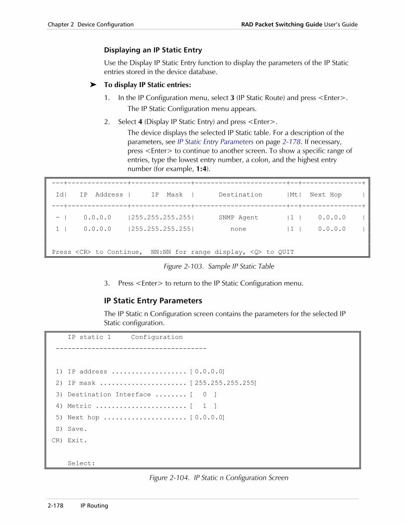
Chapter 2 Device Configuration RAD Packet Switching Guide User’s Guide
2-178 IP Routing
Displaying an IP Static Entry
Use the Display IP Static Entry function to display the parameters of the IP Static entries stored in the device database.
To display IP Static entries:
1. In the IP Configuration menu, select 3 (IP Static Route) and press <Enter>. The IP Static Configuration menu appears.
2. Select 4 (Display IP Static Entry) and press <Enter>. The device displays the selected IP Static table. For a description of the parameters, see IP Static Entry Parameters on page 2-178. If necessary, press <Enter> to continue to another screen. To show a specific range of entries, type the lowest entry number, a colon, and the highest entry number (for example, 1:4).
---+---------------+---------------+-----------------------+--+---------------+
Id| IP Address | IP Mask | Destination |Mt| Next Hop |
---+---------------+---------------+-----------------------+--+---------------+
- | 0.0.0.0 |255.255.255.255| SNMP Agent |1 | 0.0.0.0 |
1 | 0.0.0.0 |255.255.255.255| none |1 | 0.0.0.0 |
Press <CR> to Continue, NN:NN for range display, <Q> to QUIT
Figure 2-103. Sample IP Static Table
3. Press <Enter> to return to the IP Static Configuration menu.
IP Static Entry Parameters
The IP Static n Configuration screen contains the parameters for the selected IP Static configuration.
IP static 1 Configuration
--------------------------------------
1) IP address ................... [0.0.0.0]
2) IP mask ...................... [255.255.255.255]
3) Destination Interface ........ [ 0 ]
4) Metric ....................... [ 1 ]
5) Next hop ..................... [0.0.0.0]
S) Save.
CR) Exit.
Select:
Figure 2-104. IP Static n Configuration Screen

RAD Packet Switching Guide User’s Guide Chapter 2 Device Configuration
IP Routing 2-179
1) IP Address IP address of the destination device in this entry. Possible values:
X.X.X.X Each X indicates a number in the range 0 - 255. The default value is 0.0.0.0.
2) IP Mask Defines the significant bits of the IP address. Only those bits specified by the IP Mask are referred to when the device searches the IP Routing table for an IP address fitting. The rest of the bits are referred to as “don’t care” bits (0.0.0.0 is not valid). For example, consider an IP routing entry defined by the IP address 192.114.30.01 and the mask 255.255.255.0. This entry refers to all addresses beginning with 192.114.30.___ and all addresses in the range of 192.114.30.0 to 192.114.30.255. Possible values:
X.X.X.X Each X indicates a number in the range 0 - 255. The default value is 255.255.255.255.
In the default IP Routing entry (entry 200) the device does not relate to the IP Address and IP mask parameters. The device uses this entry when the datagram’s called address cannot be matched to any other Routing entry.
3) Destination Interface
The destination interface number for this routing entry. Possible values:
x The interface number.
4) Metric Exact priority level for communicating with the IP destination defined in parameter 1.Possible values:
1 - [Maximum Hop Count]
Priority level. The maximum hop count is equal to the Maximum Hop Count value of the Global IP Parameters screen (see IP Global Configuration on page 2-169).
5) Next Hop IP address of a gateway (such as a gateway out of the LAN) that transfers data out of the local LAN towards the destination. Possible values:
X.X.X.X Each X indicates a number in the range 0 - 255.
Note

Chapter 2 Device Configuration RAD Packet Switching Guide User’s Guide
2-180 ISDN
2.15 ISDN
Introduction This section provides a guide for setting up the device’s ISDN configuration. For more information about ISDN protocol, see Chapter 7, Protocols.
Receiving an ISDN Call
By default, the device is configured to receive any incoming ISDN call. The received call is directed to one of the links, in accordance with the Accept List. The Accept List provides a precise definition of the incoming calls which should be accepted and their destination links on the device.
For more information about the Accept List, see ISDN Accept List Configuration on page 2-187.
Initiating an ISDN Call
Initiating an outgoing ISDN call involves the following steps:
• Configuration of an ISDN routing entry, which states the ISDN address to be called.
• Attachment of the ISDN routing to an X.25 address, a Frame Relay DLCI, an X.25 over Frame Relay DLCI, or a PPP channel.
X.25 On an X.25 link, an X.25 call request initiates an ISDN call. The link that issues the call request is automatically selected from a pool of all ISDN links that are preconfigured as X.25. Except for a small modification, the standard routing is used. If an X.25 address is to be directed to an ISDN address, the Link value in the routing entry is Innnn, where nnnn is an index number of an entry in the ISDN routing table.
Frame Relay On a Frame Relay link, the existence of traffic on a specific DLCI initiates a call. The ISDN destination address must be configured in the DLCI x Link n Configuration screen (see DLCI Parameters on page 2-53).
X.25 over Frame Relay
If X.25 is encapsulated over frame relay, an X.25 call request initiates a call. The standard routing should be used to direct the X.25 address to the proper DLCI. The ISDN routing entry number must be configured in the DLCI x Link n Configuration screen (see DLCI Parameters on page 2-53).
PPP Traffic sent to the PPP channel initiates the ISDN call. Immediately after the call is opened, PPP negotiation starts.

RAD Packet Switching Guide User’s Guide Chapter 2 Device Configuration
ISDN 2-181
Configuration Tips
If you’re using Frame Relay over ISDN, define an Inactivity Timeout of at least 50 seconds (default setting is 180 seconds). Otherwise, the lines will not synchronize (the exact value depends on the Frame Relay port parameters).
If you’re using the Dial-Back option, set the retry period at the initiating side to at least 15 seconds. Otherwise, a retry will be initiated prior to the incoming dialback call.
When using the Dial-Back option, the PBX or carrier must supply the ISDN address of the caller. Be aware that different PBXs and carriers may or may not supply the caller’s ISDN address to the party being called. An incoming call without an ISDN address will be rejected.
Due to the delay in establishing ISDN calls, the X.25 call request timeout parameter has to be increased in all the devices that send call requests to an ISDN network.
ISDN Configuration Operations From the ISDN Configuration menu, you can:
• Set a Global Configuration· Define an ISDN Routing Table
• Define ISDN Accept parameters
• Update ISDN Link Parameters
• Display ISDN Link Parameters
To use the ISDN Configuration menu:
1. In the Configuration menu, select 15 (ISDN Configuration) and press <Enter>. The ISDN Configuration menu appears.
ISDN configuration ------------------ 1) Global Configuration. 2) ISDN Routing Table. 3) ISDN Accept List Table. 4) Update ISDN Link Parameters. 5) Display ISDN Link Parameters. CR) Exit. Select:
Figure 2-105. ISDN Configuration Menu
2. Type the number of a configuration option and press <Enter>. The appropriate menu appears.
3. To return to the Configuration menu, press <Enter> without selecting an option.
Note
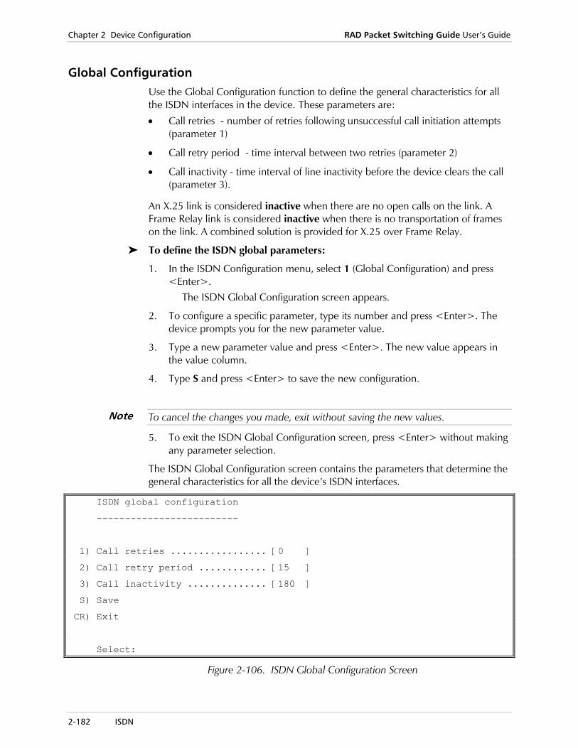
Chapter 2 Device Configuration RAD Packet Switching Guide User’s Guide
2-182 ISDN
Global Configuration Use the Global Configuration function to define the general characteristics for all the ISDN interfaces in the device. These parameters are:
• Call retries - number of retries following unsuccessful call initiation attempts (parameter 1)
• Call retry period - time interval between two retries (parameter 2)
• Call inactivity - time interval of line inactivity before the device clears the call (parameter 3).
An X.25 link is considered inactive when there are no open calls on the link. A Frame Relay link is considered inactive when there is no transportation of frames on the link. A combined solution is provided for X.25 over Frame Relay.
To define the ISDN global parameters:
1. In the ISDN Configuration menu, select 1 (Global Configuration) and press <Enter>.
The ISDN Global Configuration screen appears.
2. To configure a specific parameter, type its number and press <Enter>. The device prompts you for the new parameter value.
3. Type a new parameter value and press <Enter>. The new value appears in the value column.
4. Type S and press <Enter> to save the new configuration.
To cancel the changes you made, exit without saving the new values.
5. To exit the ISDN Global Configuration screen, press <Enter> without making any parameter selection.
The ISDN Global Configuration screen contains the parameters that determine the general characteristics for all the device’s ISDN interfaces.
ISDN global configuration
-------------------------
1) Call retries ................. [0 ]
2) Call retry period ............ [15 ]
3) Call inactivity .............. [180 ]
S) Save
CR) Exit
Select:
Figure 2-106. ISDN Global Configuration Screen
Note

RAD Packet Switching Guide User’s Guide Chapter 2 Device Configuration
ISDN 2-183
1) Call Retries Number of call retries that an ISDN interface will execute following unsuccessful call initiation attempts. Possible values:
0 - 255 Number of retries. The default value is 0.
2) Call Retry Period
Time interval between two retries. Possible values:
5 - 250 Number of seconds. The default value is 15.
3) Call Inactivity
Time interval of inactivity on the link before the device clears the call. Possible values:
0 No disconnection following inactivity.
1 - 65000 Number of seconds. The default value is 180.
Defining an ISDN Routing Table From the ISDN Routing Configuration menu, you can:
• Add an ISDN routing entry· Update an ISDN routing entry
• Delete an ISDN routing entry
• Display ISDN routing entry parameters.
To use the ISDN Routing Configuration menu:
1. In the ISDN Configuration menu, select 2 (ISDN Routing Table) and press <Enter>.
The ISDN Routing Configuration screen appears.
ISDN Routing Configuration
--------------------------
1) Add ISDN Routing Entry
2) Delete ISDN Routing Entry
3) Update ISDN Routing Entry
4) Display ISDN Routing Entry
CR) Exit
Select:
Figure 2-107. ISDN Routing Configuration Menu
2. Type the number of a function and press <Enter>. The appropriate menu appears.
3. To return to the ISDN Configuration menu, press <Enter> without selecting an option.
Chapter 2 Device Configuration RAD Packet Switching Guide User’s Guide
2-184 ISDN
Adding an ISDN Routing Entry
Use the Add ISDN Routing Entry function to add a new ISDN routing configuration to the ISDN routing table.
To add a new ISDN routing entry:
1. In the ISDN Configuration menu, select 2 (ISDN Routing Table) and press <Enter>.
The ISDN Routing Configuration screen appears.
2. Select 1 (Add ISDN Routing Entry) and press <Enter>. A list of existing ISDN routing entry numbers appears.
3. Type a number for the new entry (1 - 200) and press <Enter>. The ISDN Routing Entry n Configuration screen appears. For more information about the ISDN routing table parameters, see ISDN Routing Table Parameters on page 2-186.
4. To configure a specific parameter, type its number and press <Enter>. The device prompts you for the new parameter value.
5. Type a new parameter value and press <Enter>. The new value appears in the value column.
6. Type S and press <Enter> to save the new ISDN routing entry.
To cancel the changes you made, exit without saving the new values.
7. To add another ISDN routing entry, repeat steps 3 to 6.
8. To exit the ISDN Routing Entry n Configuration screen, press <Enter> without making any parameter selection.
Updating an ISDN Routing Entry
Use the Update ISDN Routing Entry function to display and change the parameters of an existing ISDN routing table entry.
To update an ISDN routing entry:
1. In the ISDN Configuration menu, select 2 (ISDN Routing Table) and press <Enter>.
The ISDN Routing Configuration screen appears.
2. Select 3 (Update ISDN Routing Entry) and press <Enter>. A list of existing ISDN routing entry numbers appears.
3. Type the number of the entry (1 - 200) you want to update and press <Enter>.
The ISDN Routing Entry n Configuration screen appears. The entry number (n) is identified in the screen title.
4. Repeat steps 3 - 7 of the procedure in the section, Adding an ISDN Routing Entry on page 2-184.
Note

RAD Packet Switching Guide User’s Guide Chapter 2 Device Configuration
ISDN 2-185
Deleting an ISDN Routing Entry
Use the Delete ISDN Routing Entry function to delete an existing ISDN routing entry from the device’s ISDN routing table.
To delete an ISDN routing entry:
1. In the ISDN Configuration menu, select 2 (ISDN Routing Table) and press <Enter>.
The ISDN Routing Configuration screen appears.
2. Select 2 (Delete ISDN Routing Entry) and press <Enter>. A list of existing ISDN routing entry numbers appears.
3. Type the number (1 - 200) of the entry that you want to delete and press <Enter>.
After the deletion, the device returns to the ISDN Routing Configuration menu.
Displaying ISDN Routing Entry Parameters
Use the Display ISDN Routing Entry function to display the parameters of the ISDN routing table entries stored in the device database.
To display ISDN routing table entries:
1. In the ISDN Configuration menu, select 2 (ISDN Routing Table) and press <Enter>.
The ISDN Routing Configuration screen appears.
2. Select 4 (Display ISDN Routing Entry) and press <Enter>. The device displays its ISDN routing table. For a description of the parameters, see ISDN Routing Table Parameters on page 2-186. If necessary, press <Enter> to continue to another screen. To show a specific range of entries, type the lowest entry number, a colon, and the highest entry number (for example, 1:2).
---+-----------------+------+-+-+
Id | Outgoing | Sub |S|O|
| Address | Addr.|P|P|
---+-----------------+------+-+-+
1 | | |1|0|
Press <CR> to Continue, NN:NN for range display, <Q> to QUIT
Figure 2-108. Sample ISDN Routing Table
3. Type Q to return to the ISDN Routing Configuration menu.
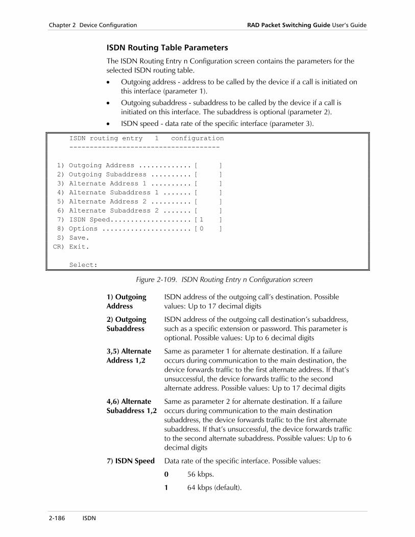
Chapter 2 Device Configuration RAD Packet Switching Guide User’s Guide
2-186 ISDN
ISDN Routing Table Parameters
The ISDN Routing Entry n Configuration screen contains the parameters for the selected ISDN routing table.
• Outgoing address - address to be called by the device if a call is initiated on this interface (parameter 1).
• Outgoing subaddress - subaddress to be called by the device if a call is initiated on this interface. The subaddress is optional (parameter 2).
• ISDN speed - data rate of the specific interface (parameter 3).
ISDN routing entry 1 configuration ------------------------------------- 1) Outgoing Address ............. [ ] 2) Outgoing Subaddress .......... [ ] 3) Alternate Address 1 .......... [ ] 4) Alternate Subaddress 1 ....... [ ] 5) Alternate Address 2 .......... [ ] 6) Alternate Subaddress 2 ....... [ ] 7) ISDN Speed.................... [1 ] 8) Options ...................... [0 ] S) Save. CR) Exit. Select:
Figure 2-109. ISDN Routing Entry n Configuration screen
1) Outgoing Address
ISDN address of the outgoing call’s destination. Possible values: Up to 17 decimal digits
2) Outgoing Subaddress
ISDN address of the outgoing call destination’s subaddress, such as a specific extension or password. This parameter is optional. Possible values: Up to 6 decimal digits
3,5) Alternate Address 1,2
Same as parameter 1 for alternate destination. If a failure occurs during communication to the main destination, the device forwards traffic to the first alternate address. If that’s unsuccessful, the device forwards traffic to the second alternate address. Possible values: Up to 17 decimal digits
4,6) Alternate Subaddress 1,2
Same as parameter 2 for alternate destination. If a failure occurs during communication to the main destination subaddress, the device forwards traffic to the first alternate subaddress. If that’s unsuccessful, the device forwards traffic to the second alternate subaddress. Possible values: Up to 6 decimal digits
7) ISDN Speed Data rate of the specific interface. Possible values:
0 56 kbps.
1 64 kbps (default).

RAD Packet Switching Guide User’s Guide Chapter 2 Device Configuration
ISDN 2-187
8) Options Additional option for defining the ISDN functionality of the local device. Possible values:
0 No options (default).
1 Reactivate transmission over the main link. This option is used if the link is defined as a backup.
ISDN Accept List Configuration Incoming call routing and security are provided by the Accept List mechanism. The Accept List is a list of entries that holds information regarding ISDN calling addresses, from which it is possible to receive a call. Each entry specifies Primary and Secondary link numbers to which the incoming call should be directed. This way, opening a specific ISDN call can be prioritized on one of the two possible links.
The primary link number is mandatory, and the secondary link number is optional. For example, if the secondary link number configuration remains empty, there will be no attempt to direct the call to the secondary link after a failure to direct the call to the primary link.
From the ISDN Accept List Configuration, you can:
• Add an ISDN accept list entry
• Update an ISDN accept list entry
• Delete an ISDN accept list entry
• Display ISDN accept list parameters.
To use the ISDN Accept List Configuration menu:
1. In the ISDN Configuration menu, select 3 (ISDN Accept List Table) and press <Enter>.
The ISDN Accept List Configuration screen appears.
ISDN Accept List Configuration ------------------------------ 1) Add ISDN Accept List Entry. 2) Delete ISDN Accept List Entry. 3) Update ISDN Accept List Entry. 4) Display ISDN Accept List Entry. CR) Exit. Select:
Figure 2-110. ISDN Accept List Configuration Menu
2. Type the number of a function and press <Enter>. The appropriate menu appears.
3. To return to the ISDN Configuration menu, press <Enter> without selecting an option.
Chapter 2 Device Configuration RAD Packet Switching Guide User’s Guide
2-188 ISDN
Adding an ISDN Accept List Entry
Use the Add ISDN Accept List Entry function to add a new entry to the ISDN Accept List table.
To add a new ISDN Accept List entry:
1. In the ISDN Configuration menu, select 3 (ISDN Accept List Table) and press <Enter>.
The ISDN Accept List Configuration screen appears.
2. Select 1 (Add ISDN Accept List Entry) and press <Enter>. A list of existing ISDN Accept List entry numbers appears.
3. Type a number for the new entry (1 - 200) and press <Enter>. The ISDN Accept List Entry n Configuration screen appears. For more information about the ISDN Accept List parameters, see ISDN Accept List Parameters on page 2-190.
4. To configure a specific parameter, type its number and press <Enter>. The device prompts you for the new parameter value.
5. Type a new parameter value and press <Enter>. The new value appears in the value column.
6. Type S and press <Enter> to save the new ISDN Accept List entry.
To cancel the changes you made, exit without saving the new values.
7. To add another ISDN Accept List entry, repeat steps 3 to 6.
8. To exit the ISDN Accept List Entry n Configuration screen, press <Enter> without making any parameter selection.
Updating an ISDN Accept List Entry
Use the Update ISDN Accept List Entry function to display and change the parameters of an existing ISDN routing table entry.
To update an ISDN Accept List entry:
1. In the ISDN Configuration menu, select 3 (ISDN Accept List Table) and press <Enter>.
The ISDN Accept List Configuration screen appears.
2. Select 3 (Update ISDN Accept List Entry) and press <Enter>. A list of existing ISDN Accept List entry numbers appears.
3. Type the number of the entry (1 - 200) you want to update and press <Enter>.
The ISDN Accept List Entry n Configuration screen appears. The entry number (n) is identified in the screen title.
4. Repeat steps 3 - 7 of the procedure in the section, Adding an ISDN Accept List Entry on page 2-188.
Note
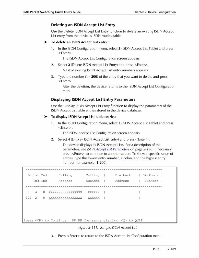
RAD Packet Switching Guide User’s Guide Chapter 2 Device Configuration
ISDN 2-189
Deleting an ISDN Accept List Entry
Use the Delete ISDN Accept List Entry function to delete an existing ISDN Accept List entry from the device’s ISDN routing table.
To delete an ISDN Accept List entry:
1. In the ISDN Configuration menu, select 3 (ISDN Accept List Table) and press <Enter>.
The ISDN Accept List Configuration screen appears.
2. Select 2 (Delete ISDN Accept List Entry) and press <Enter>. A list of existing ISDN Accept List entry numbers appears.
3. Type the number (1 - 200) of the entry that you want to delete and press <Enter>.
After the deletion, the device returns to the ISDN Accept List Configuration menu.
Displaying ISDN Accept List Entry Parameters
Use the Display ISDN Accept List Entry function to display the parameters of the ISDN Accept List table entries stored in the device database.
To display ISDN Accept List table entries:
1. In the ISDN Configuration menu, select 3 (ISDN Accept List Table) and press <Enter>.
The ISDN Accept List Configuration screen appears.
2. Select 4 (Display ISDN Accept List Entry) and press <Enter>. The device displays its ISDN Accept Lists. For a description of the parameters, see ISDN Accept List Parameters on page 2-190. If necessary, press <Enter> to continue to another screen. To show a specific range of entries, type the lowest entry number, a colon, and the highest entry number (for example, 1:200).
---+---+---+-----------------+----------+-----------------+----------+
Id|1st|2nd| Calling | Calling | Dialback | Dialback |
|Lnk|Lnk| Address | SubAddr | Address | SubAddr |
---+---+---+-----------------+----------+-----------------+----------+
1 | A | 0 |XXXXXXXXXXXXXXXXX| XXXXXX | | |
200| A | 0 |XXXXXXXXXXXXXXXXX| XXXXXX | | |
Press <CR> to Continue, NN:NN for range display, <Q> to QUIT
Figure 2-111. Sample ISDN Accept List
3. Press <Enter> to return to the ISDN Accept List Configuration menu.

Chapter 2 Device Configuration RAD Packet Switching Guide User’s Guide
2-190 ISDN
ISDN Accept List Parameters
The ISDN Accept List Entry n Configuration screen contains the parameters for the device’s ISDN Accept List.
• Primary Link Number - number of the link on the receiving ISDN interface that the device will call (parameter 1)
• Secondary Link Number - number of the link on the receiving ISDN interface that the device will call if the primary number is not available (parameter 2)
• Calling Address parameters: the address and subaddress of the ISDN interface, for receiving an incoming call (parameters 3 + 4)
• Dialback Address parameters: the address and subaddress of the ISDN interface on the other end of the link (parameters 5 + 6)
ISDN accept list entry 1 configuration
------------------------------------------
1) Primary Link Number .......... [A ]
2) Secondary link number ........ [0 ]
3) Calling Address .............. [XXXXXXXXXXXXXXXXX]
4) Calling Subaddress............ [XXXXXX]
5) Dialback Address ............. [ ]
6) Dialback Subaddress .......... [ ]
S) Save.
CR) Exit.
Select:
Figure 2-112. ISDN Accept List Entry Configuration Screen
1) Primary Link Number
Number of the link on the receiving ISDN interface that the device calls first. Possible values:
A First available link at the destination address (default).
Any valid ISDN link number
A specific ISDN link.
2) Secondary Link Number
Number of the link on the receiving ISDN interface that the device calls if the call to the primary link failed. Possible values:
0 No secondary link.
Complementary number to the primary link number.
Complementary links are [1;2], [3,4], [5;6] and [7;8] on FPS-8 device. [1;2] and [7;8] on other devices.
If the primary link number is set to A, the secondary link number must be 0.
Note
RAD Packet Switching Guide User’s Guide Chapter 2 Device Configuration
ISDN 2-191
3) Calling Address
ISDN address of the incoming call. The calling address and subaddress are used for security. The device will accept only calls whose address and subaddress match the configured values. “Don’t care” digits (‘x’) are valid in order to enable a partial match. Possible values:
Up to 17 decimal digits or Xs (“don’t care” digits).
Valid ISDN address.
4) Calling Subaddress
ISDN subaddress (if it exists) of the incoming call. Possible values:
Up to 6 decimal digits or Xs (“don’t care” digits).
Valid ISDN subaddress.
5) Dialback Address
ISDN address that the ISDN interface will call when it receives a call, in order to confirm that the sender is acceptable. Dial-Back occurs only if Dial-Back parameters are configured. In such a case, an incoming call, which matches the Accept List entry, is rejected and a dial-back process starts. Possible values:
Up to 17 decimal digits. Valid ISDN address.
6) Dialback Subaddress
Subaddress of the number that the ISDN interface will call when it receives a call, in order to confirm that the sender is acceptable. Possible values:
Up to 6 decimal digits. Valid ISDN subaddress.
Updating ISDN Link Parameters Use the Update ISDN Link Parameters function to define the parameters for a selected ISDN link on the device. These parameters are:
• ISDN Protocol Type - ISDN protocol type for the link (parameter 1)
• ISDN Channel - Channel to be used if the ISDN link is used as a leased line (parameter 2).
This parameter is used only for leased line. It defines the channel to be used: B1, B2, or B1 + B2.
The selected channel must conform to the channel and protocol type selected on the other link on the same ISDN interface.
• Calling Address parameters - Address and subaddress of the link (parameters 3 + 4).
These values are used to provide identification in outgoing calls, originated on this link.
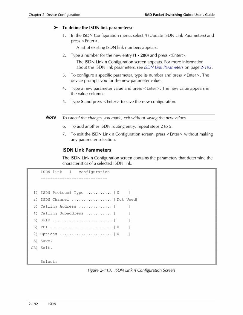
Chapter 2 Device Configuration RAD Packet Switching Guide User’s Guide
2-192 ISDN
To define the ISDN link parameters:
1. In the ISDN Configuration menu, select 4 (Update ISDN Link Parameters) and press <Enter>.
A list of existing ISDN link numbers appears.
2. Type a number for the new entry (1 - 200) and press <Enter>. The ISDN Link n Configuration screen appears. For more information about the ISDN link parameters, see ISDN Link Parameters on page 2-192.
3. To configure a specific parameter, type its number and press <Enter>. The device prompts you for the new parameter value.
4. Type a new parameter value and press <Enter>. The new value appears in the value column.
5. Type S and press <Enter> to save the new configuration.
To cancel the changes you made, exit without saving the new values.
6. To add another ISDN routing entry, repeat steps 2 to 5.
7. To exit the ISDN Link n Configuration screen, press <Enter> without making any parameter selection.
ISDN Link Parameters
The ISDN Link n Configuration screen contains the parameters that determine the characteristics of a selected ISDN link.
ISDN link 1 configuration
----------------------------
1) ISDN Protocol Type ........... [0 ]
2) ISDN Channel ................. [Not Used]
3) Calling Address .............. [ ]
4) Calling Subaddress ........... [ ]
5) SPID ......................... [ ]
6) TEI .......................... [0 ]
7) Options ...................... [0 ]
S) Save.
CR) Exit.
Select:
Figure 2-113. ISDN Link n Configuration Screen
Note

RAD Packet Switching Guide User’s Guide Chapter 2 Device Configuration
ISDN 2-193
1) ISDN Protocol Type
Type of ISDN protocol to be used by the link. The value of this parameter automatically sets the corresponding protocol type parameter of the complementary link. Possible values:
0 ETSI - the European ISDN protocol (default).
1 NTT - a variant of the ETSI.
2 Leased - a physical Point-To-Point protocol, which does not require dialing, because the two ends of the link are connected on a fixed basis.
3 5 ESS
4 National 1
5 DMS 100
6 5 ESS PTP
2) ISDN Channel
B channels that are used on the ISDN link (Leased Line only). Possible values:
0 No Channel
1 B1
2 B2
3 B1 + B2
3)Calling Address
ISDN address of the incoming call. The calling address and subaddress are used for security. The device will accept only calls whose address and subaddress match the configured values. Possible values:
Up to 17 decimal digits. Valid ISDN address.
4) Calling Subaddress
ISDN subaddress (if it exists) of the incoming call. Possible values:
Up to 6 decimal digits. Valid ISDN subaddress.
5) SPID Service Provider ID. Possible values:
Up to 22 decimal digits. Valid ISDN subaddress.
6) TEI Terminal identifying number. Possible values:
0 Dynamic TEI (default).
1 - 63 Terminal ID number.
7) Options Additional option for defining the ISDN functionality of the selected link. Possible values:
0 No options (default).
1 Disable Point to Multipoint option.

Chapter 2 Device Configuration RAD Packet Switching Guide User’s Guide
2-194 ISDN
Displaying ISDN Link Parameters Use the Display ISDN Link Parameters function to display the parameters of all the device’s ISDN links.
1. In the ISDN Configuration menu, select 5 (Display ISDN Link Parameters) and press <Enter>.
A list of the ISDN link entries appears. For a description of the parameters, see ISDN Link Parameters on page 2-192. If necessary, press <Enter> to continue to another screen. To show a specific range of entries, type the lowest entry number, a colon, and the highest entry number (for example, 1:2).
----+----+----------+-------------------+----------+
ID.|ISDN| ISDN | Calling | Call |
|type| Channel | Address | Subaddr |
----+----+----------+-------------------+----------+
1 | 0 | not used | | |
Press <CR> to Continue, NN:NN for range display, <Q> to QUIT
Figure 2-114. Sample ISDN Link Parameters Screen
2. Type Q to return to the ISDN Configuration menu.
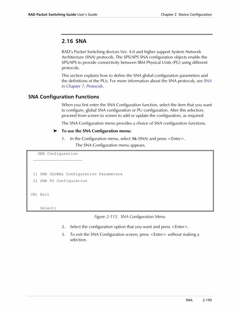
RAD Packet Switching Guide User’s Guide Chapter 2 Device Configuration
SNA 2-195
2.16 SNA
RAD’s Packet Switching devices Ver. 4.0 and higher support System Network Architecture (SNA) protocols. The SPS/APS SNA configuration objects enable the SPS/APS to provide connectivity between IBM Physical Units (PU) using different protocols.
This section explains how to define the SNA global configuration parameters and the definitions of the PUs. For more information about the SNA protocols, see SNA in Chapter 7, Protocols.
SNA Configuration Functions When you first enter the SNA Configuration function, select the item that you want to configure, global SNA configuration or PU configuration. After this selection, proceed from screen to screen to add or update the configuration, as required.
The SNA Configuration menu provides a choice of SNA configuration functions.
To use the SNA Configuration menu:
1. In the Configuration menu, select 16 (SNA) and press <Enter>. The SNA Configuration menu appears.
SNA Configuration
---------------------
1) SNA GLOBAL Configuration Parameters
2) SNA PU Configuration
CR) Exit
Select:
Figure 2-115. SNA Configuration Menu
2. Select the configuration option that you want and press <Enter>.
3. To exit the SNA Configuration screen, press <Enter> without making a selection.

Chapter 2 Device Configuration RAD Packet Switching Guide User’s Guide
2-196 SNA
SNA Global Configuration Use the SNA Global Configuration Parameters function to define the common parameters for all PU definitions in the device’s SNA subsystem.
To define the SNA global parameters:
1. In the Configuration menu, select 16 (SNA) and press <Enter>. The SNA Configuration menu appears.
2. Select 1 (SNA Global Configuration Parameters) and press <Enter>. The SNA Global Configuration screen appears. For a description of the parameters, see SNA Global Configuration on page 2-196.
3. To configure a specific parameter, type its number and press <Enter>. The device prompts you for the new parameter value.
4. Type a new parameter value and press <Enter>. The new value appears in the value column.
5. Type S and press <Enter> to save the new configuration.
To cancel the changes you made, exit without saving the new values.
6. To exit the SNA Global Configuration screen, press <Enter> without making any parameter selection.
The SNA Global Configuration screen contains the device’s common SNA parameters.
SNA GLOBAL Configuration
----------------------------
1) RFC 1490 Source MAC Address .............. [400000000001]
2) ETHERNET Source MAC Address .............. [400000000012]
3) Default FR Port and DLCI(RFC 1490 only)... [0:0 ]
S) Save
CR) Exit
Select:
Figure 2-116. SNA Global Parameters Configuration Menu
1) RFC 1490 Source MAC Address
Source MAC address of the local device, used for all connections of PU’s over a Frame Relay network. Possible values:
12 hexadecimal number
Any valid MAC address. The default value is 400000000001.
Note
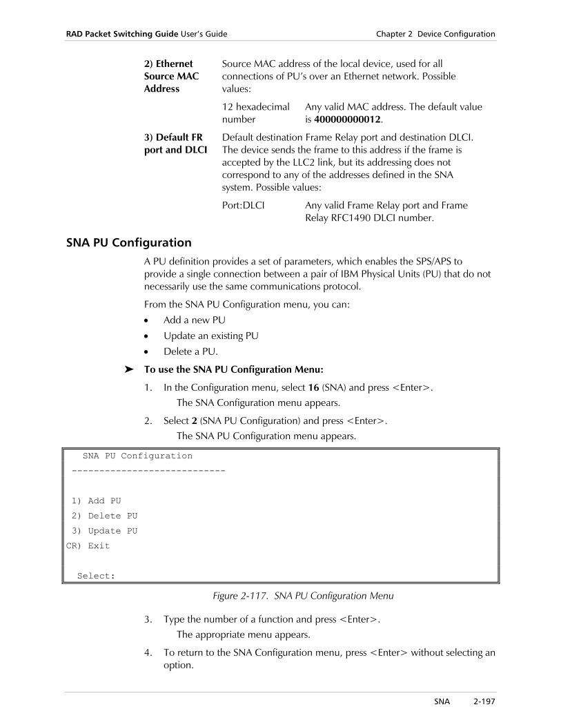
RAD Packet Switching Guide User’s Guide Chapter 2 Device Configuration
SNA 2-197
2) Ethernet Source MAC Address
Source MAC address of the local device, used for all connections of PU’s over an Ethernet network. Possible values:
12 hexadecimal number
Any valid MAC address. The default value is 400000000012.
3) Default FR port and DLCI
Default destination Frame Relay port and destination DLCI. The device sends the frame to this address if the frame is accepted by the LLC2 link, but its addressing does not correspond to any of the addresses defined in the SNA system. Possible values:
Port:DLCI Any valid Frame Relay port and Frame Relay RFC1490 DLCI number.
SNA PU Configuration A PU definition provides a set of parameters, which enables the SPS/APS to provide a single connection between a pair of IBM Physical Units (PU) that do not necessarily use the same communications protocol.
From the SNA PU Configuration menu, you can:
• Add a new PU
• Update an existing PU
• Delete a PU.
To use the SNA PU Configuration Menu:
1. In the Configuration menu, select 16 (SNA) and press <Enter>. The SNA Configuration menu appears.
2. Select 2 (SNA PU Configuration) and press <Enter>. The SNA PU Configuration menu appears.
SNA PU Configuration
----------------------------
1) Add PU
2) Delete PU
3) Update PU
CR) Exit
Select:
Figure 2-117. SNA PU Configuration Menu
3. Type the number of a function and press <Enter>. The appropriate menu appears.
4. To return to the SNA Configuration menu, press <Enter> without selecting an option.
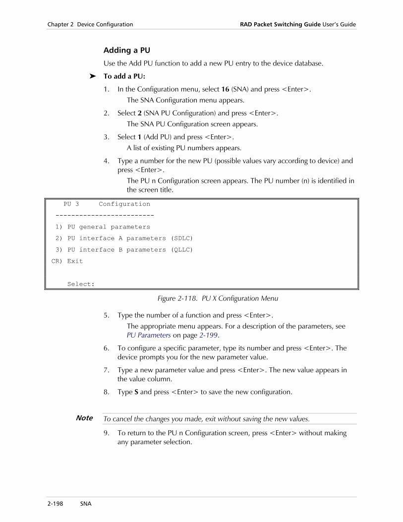
Chapter 2 Device Configuration RAD Packet Switching Guide User’s Guide
2-198 SNA
Adding a PU
Use the Add PU function to add a new PU entry to the device database.
To add a PU:
1. In the Configuration menu, select 16 (SNA) and press <Enter>. The SNA Configuration menu appears.
2. Select 2 (SNA PU Configuration) and press <Enter>. The SNA PU Configuration screen appears.
3. Select 1 (Add PU) and press <Enter>. A list of existing PU numbers appears.
4. Type a number for the new PU (possible values vary according to device) and press <Enter>.
The PU n Configuration screen appears. The PU number (n) is identified in the screen title.
PU 3 Configuration
-------------------------
1) PU general parameters
2) PU interface A parameters (SDLC)
3) PU interface B parameters (QLLC)
CR) Exit
Select:
Figure 2-118. PU X Configuration Menu
5. Type the number of a function and press <Enter>. The appropriate menu appears. For a description of the parameters, see PU Parameters on page 2-199.
6. To configure a specific parameter, type its number and press <Enter>. The device prompts you for the new parameter value.
7. Type a new parameter value and press <Enter>. The new value appears in the value column.
8. Type S and press <Enter> to save the new configuration.
To cancel the changes you made, exit without saving the new values.
9. To return to the PU n Configuration screen, press <Enter> without making any parameter selection.
Note
RAD Packet Switching Guide User’s Guide Chapter 2 Device Configuration
SNA 2-199
Updating a PU
Use the Update PU function to display and change the parameters of an existing PU.
To update a PU:
1. In the Configuration menu, select 16 (SNA) and press <Enter>. The SNA Configuration menu appears.
2. Select 2 (SNA PU Configuration) and press <Enter>. The SNA PU Configuration screen appears.
3. Select 3 (Update PU) and press <Enter>. A list of existing PU numbers appears.
4. Type the entry number of the PU you want to update and press <Enter>. The PU n Configuration screen appears. The management station number (n) is identified in the screen title.
5. Repeat steps 5–8 of the procedure in the section Adding a PU on page 2-198.
Deleting a PU
Use the Delete PU function to delete an existing PU entry from the device database.
To delete a PU:
1. In the Configuration menu, select 16 (SNA) and press <Enter>. The SNA Configuration menu appears.
2. Select 2 (SNA PU Configuration) and press <Enter>. The SNA PU Configuration screen appears.
3. Select 2 (Delete PU) and press <Enter>. A list of existing PU numbers appears.
4. Type the entry number of the PU that you want to delete and press <Enter>. After the deletion, the device returns to the SNA PU Configuration menu.
PU Parameters A PU definition provides a set of parameters, which enables the SPS/APS to provide a single connection between a pair of IBM Physical Units (PU) that do not necessarily use the same communications protocol.
A PU definition includes the following:
• PU General parameters
• PU Interface A parameters. The interface’s protocol appears in parentheses in the PU n Configuration menu.
• PU Interface B parameters. The interface’s protocol appears in parentheses in the PU n Configuration menu.
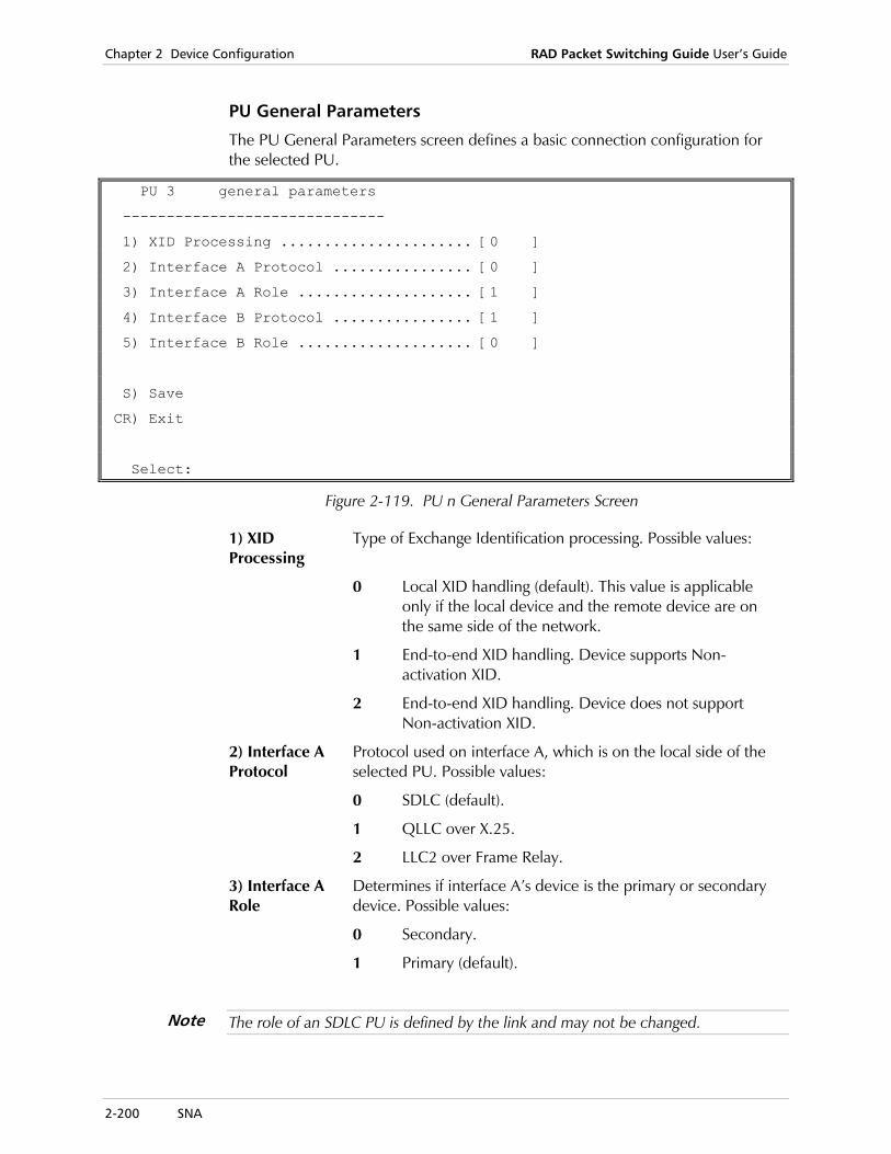
Chapter 2 Device Configuration RAD Packet Switching Guide User’s Guide
2-200 SNA
PU General Parameters
The PU General Parameters screen defines a basic connection configuration for the selected PU.
PU 3 general parameters
------------------------------
1) XID Processing ...................... [0 ]
2) Interface A Protocol ................ [0 ]
3) Interface A Role .................... [1 ]
4) Interface B Protocol ................ [1 ]
5) Interface B Role .................... [0 ]
S) Save
CR) Exit
Select:
Figure 2-119. PU n General Parameters Screen
1) XID Processing
Type of Exchange Identification processing. Possible values:
0 Local XID handling (default). This value is applicable only if the local device and the remote device are on the same side of the network.
1 End-to-end XID handling. Device supports Non-activation XID.
2 End-to-end XID handling. Device does not support Non-activation XID.
2) Interface A Protocol
Protocol used on interface A, which is on the local side of the selected PU. Possible values:
0 SDLC (default).
1 QLLC over X.25.
2 LLC2 over Frame Relay.
3) Interface A Role
Determines if interface A’s device is the primary or secondary device. Possible values:
0 Secondary.
1 Primary (default).
The role of an SDLC PU is defined by the link and may not be changed.
Note

RAD Packet Switching Guide User’s Guide Chapter 2 Device Configuration
SNA 2-201
4) Interface B Protocol
Protocol used on interface B, which is on the second side of the selected PU. Possible values:
0 SDLC.
1 QLLC over X.25 (default).
2 LLC2 over Frame Relay.
5) Interface B Role
Determines if the interface B’s device is the primary or secondary device. Possible values:
0 Secondary (default).
1 Primary.
The role of an SDLC PU is defined by the link and may not be changed.
Interface Parameters (for sides A and B)
After selecting the interface’s protocol, you can define its parameters. The PU Interface Configuration screen varies according to the protocol of the selected interface:
• SDLC protocol
• QLLC/X.25 protocol
• LLC2 over Frame Relay protocol.
SDLC Parameters
The PU n Interface Configuration screen contains the SDLC protocol parameters for Interface A or B of a PU, if applicable.
For SDLC link configuration, see SDLC Parameters on page 2-66.
PU 3 Interface A SDLC configuration ---------------------------------------------- 1) Link Number ......................... [0 ] 2) SDLC Address ........................ [00 ] 3) Group Address........................ [00 ] 4) IDBLK (Local XID only) .............. [017 ] 5) IDNUM (Local XID only) .............. [00000] 6) XID Initiation (End-to-End XID only). [0 ] 7) Max PIU size ........................ [521 ] 8) Transmit Window ..................... [7 ] 9) Poll Timer (Primary only) ........... [7 ] S) Save CR) Exit Select:
Figure 2-120. PU n Interface A SDLC Configuration Screen
Note

Chapter 2 Device Configuration RAD Packet Switching Guide User’s Guide
2-202 SNA
1) Link Number
Specific device link number to which this PU is attached. Possible values: Any SDLC link number. The default value is 0.
This SPS/APS link must be set to SDLC protocol (see Set Link Type on page 2-32).
2) SDLC Address
SDLC address of the attached device. Possible values: Hexadecimal number in the range 00 - FE. The default value is 00.
3) Group Address
Common address for several devices, which may be configured in a group. Some IBM devices support a Group Address. If you want to connect several of these devices to the SPS/APS, define the same Group Address for all these devices. Possible values: a Hexadecimal number in the range 00 - FE. The default value is 00.
4) IDBLK IDBLK is required for Local XID Processing only. This parameter must match the IDBLK configured on the attached device. Possible values: Up to 3 Hexadecimal digits. The default value is 017.
5) IDNUM IDNUM must match the IDNUM configured on the attached device. Possible values: Up to 5 Hexadecimal digits. The default value is 00000.
6)XID Initiation
This parameter is used primarily for testing by technical support personnel. Possible values:
0 Do not initiate an XID message.
1 Initiate an XID message to SDLC.
It is recommended to keep this parameter at its default value.
7) Max PIU Size
Maximum size of a frame. Possible values:
137 - 7642 Number of bytes. The default value is 521.
8) Transmit Window
Maximum number of frames that the device transmits without receiving acknowledgment from the PU. Possible values:
1 - 7 Number of frames. The default value is 7.
9) Poll Timer Time interval between two polls. This parameter is applicable for a primary interface only. Possible values:
1 - 65535 Number of clock ticks (1 clock tick = 50 ms). The default value is 7. For example, 7 represents an interval of 350 ms.
Note
Note
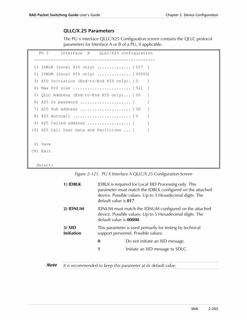
RAD Packet Switching Guide User’s Guide Chapter 2 Device Configuration
SNA 2-203
QLLC/X.25 Parameters
The PU n Interface QLLC/X25 Configuration screen contains the QLLC protocol parameters for Interface A or B of a PU, if applicable.
PU 3 Interface B QLLC/X25 configuration
--------------------------------------------------
1) IDBLK (Local XID only) .............. [017 ]
2) IDNUM (Local XID only) .............. [00000]
3) XID Initiation (End-to-End XID only). [0 ]
4) Max PIU size ........................ [521 ]
5) QLLC Address (End-to-End XID only)... [00 ]
6) X25 In password ..................... [ ]
7) X25 Sub address ..................... [00 ]
8) X25 Autocall ........................ [0 ]
9) X25 Called address .................. [ ]
10) X25 Call User Data and Facilities ... [ ]
S) Save
CR) Exit
Select:
Figure 2-121. PU X Interface A QLLC/X.25 Configuration Screen
1) IDBLK IDBLK is required for Local XID Processing only. This parameter must match the IDBLK configured on the attached device. Possible values: Up to 3 Hexadecimal digits. The default value is 017.
2) IDNUM IDNUM must match the IDNUM configured on the attached device. Possible values: Up to 5 Hexadecimal digits. The default value is 00000.
3) XID Initiation
This parameter is used primarily for testing by technical support personnel. Possible values:
0 Do not initiate an XID message.
1 Initiate an XID message to SDLC.
It is recommended to keep this parameter at its default value.
Note

Chapter 2 Device Configuration RAD Packet Switching Guide User’s Guide
2-204 SNA
4) Max PIU Size
Maximum size of a packet. Possible values:
137 - 7642 Number of bytes. The default value is 521.
5) QLLC Address
Applicable for End-to-End XID Processing only. Possible values:
Default value only The default value is 00.
The value of this parameter should not be modified from its default value.
6) X.25 In Password
A password for receiving calls on the selected interface. If used, all incoming call indications must specify this password. Possible values:
Up to 8 characters.
The default value is a blank field (no password).
7) X.25 Subaddress
X.25 subaddress of the PU. Possible values:
00 No subaddress (default).
01 - 99 X.25 subaddress number.
8) X.25 Autocall
Initiation of an X.25 call request. When set, the PU automatically sends a call request. Possible values:
0 No call request sent (default).
1 After connection, the device automatically sends a call request to the X.25 Called Address (Parameter 9).
9) X.25 Called Address
X.25 address to which the device automatically sends a call request. Possible values:
Up to 15 digits. Valid X.25 address.
This parameter is relevant only when X.25 Autocall (parameter 8) is set to 1.
10) X.25 Call User Data and Facilities
When the SPS/APS PU sends a call request, it can include Facilities and Call User Data. The Call User Data is encoded in hexadecimal, in order to enable the inclusion of non-printable characters. This parameter is applicable for outgoing calls only and is used with the X.25 Called address and X.25 autocall parameters. Possible values:
Up to 60 hexadecimal digits.
Each pair of digits represents one byte in the manner shown below:
Digit number 0 1 2 3 4 5 58 59 max. 60 digits
Byte number 0 1 2..........29 max. 30 bytes
Byte 0 (digits 0 and 1) is reserved for X.25 Facilities. The remaining bytes define the Call User Data, as it will appear in the call request packet.
Note
Note

RAD Packet Switching Guide User’s Guide Chapter 2 Device Configuration
SNA 2-205
Call Facilities
Byte 0 defines the X.25 Facilities:
Digit No. 0 controls X.25 packet size negotiation.
• 1 signifies that packet size negotiation is enabled.
• 0 signifies that packet size negotiation is disabled.
Digit No. 1 controls packet window negotiation.
• 1 signifies that packet window negotiation is enabled.
• 0 signifies that packet window negotiation is disabled.
Valid values for byte 0 are: 10, 01, 11, and 00.
• 00 signifies that no facilities will be used.
We recommend that you use packet size and packet window negotiation to make your network tolerant of configuration mismatches. If you use these negotiations, make sure that each “hop” on the route between the SPS and that the remote DTE also supports this feature.
Call User Data
Bytes 1 through 29 (digits 2 through 59) form a contiguous 29-byte field, which defines the X.25 call user data. This data is then sent in the Call Request packets initiated by the SPS/APS PU.
Examples for Call User Data and Facilities Coding
• Packet Size Negotiation = yes, Packet Window Negotiation = yes, No user data
Value=11
Explanation:
byte 0 bytes 1 to 29
digit 0 digit 1
Packet Size Negotiation = yes 1 --
Packet Window Negotiation = yes -- 1
No user data --
---------------------------------------------
Value = 11 1 1
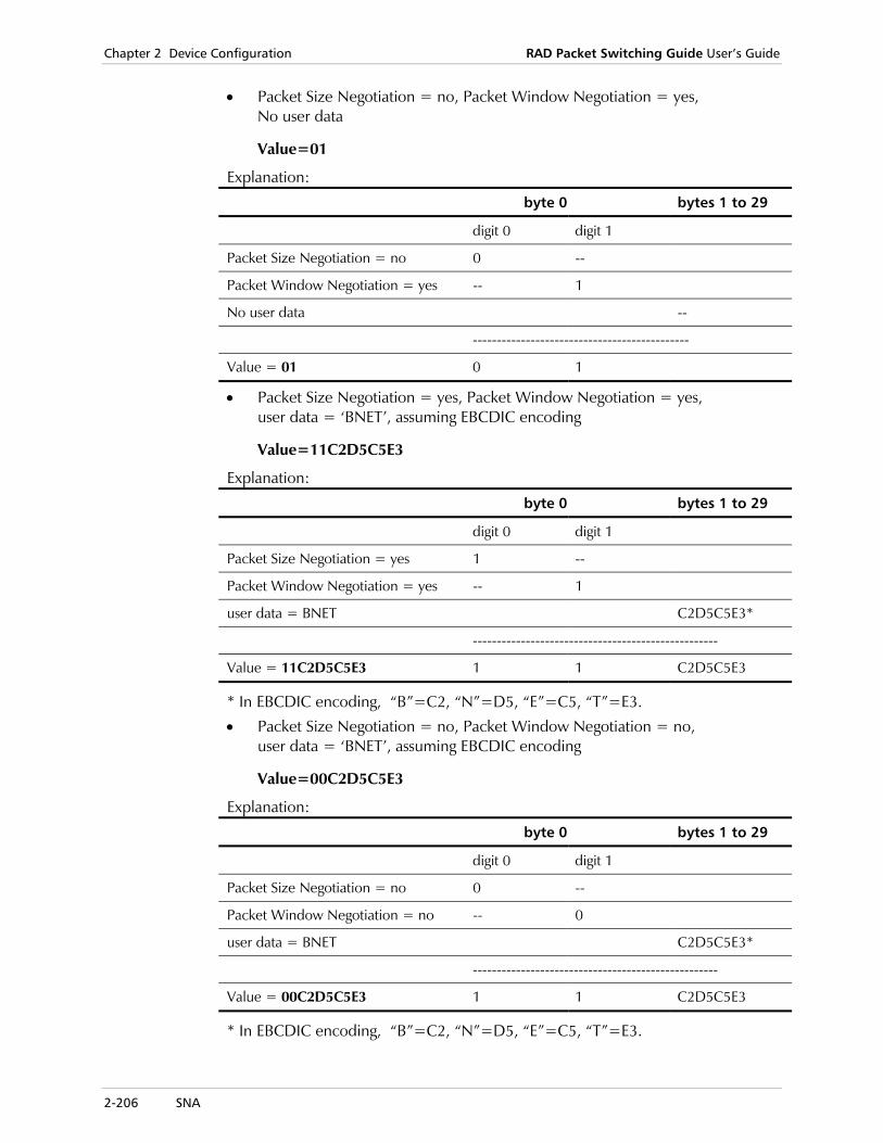
Chapter 2 Device Configuration RAD Packet Switching Guide User’s Guide
2-206 SNA
• Packet Size Negotiation = no, Packet Window Negotiation = yes, No user data
Value=01
Explanation:
byte 0 bytes 1 to 29
digit 0 digit 1
Packet Size Negotiation = no 0 --
Packet Window Negotiation = yes -- 1
No user data --
---------------------------------------------
Value = 01 0 1
• Packet Size Negotiation = yes, Packet Window Negotiation = yes, user data = ‘BNET’, assuming EBCDIC encoding
Value=11C2D5C5E3
Explanation:
byte 0 bytes 1 to 29
digit 0 digit 1
Packet Size Negotiation = yes 1 --
Packet Window Negotiation = yes -- 1
user data = BNET C2D5C5E3*
---------------------------------------------------
Value = 11C2D5C5E3 1 1 C2D5C5E3
* In EBCDIC encoding, “B”=C2, “N”=D5, “E”=C5, “T”=E3.
• Packet Size Negotiation = no, Packet Window Negotiation = no, user data = ‘BNET’, assuming EBCDIC encoding
Value=00C2D5C5E3
Explanation:
byte 0 bytes 1 to 29
digit 0 digit 1
Packet Size Negotiation = no 0 --
Packet Window Negotiation = no -- 0
user data = BNET C2D5C5E3*
---------------------------------------------------
Value = 00C2D5C5E3 1 1 C2D5C5E3
* In EBCDIC encoding, “B”=C2, “N”=D5, “E”=C5, “T”=E3.
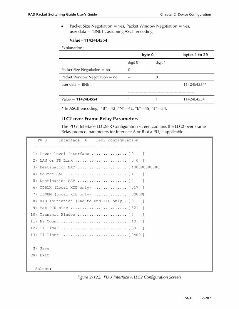
RAD Packet Switching Guide User’s Guide Chapter 2 Device Configuration
SNA 2-207
• Packet Size Negotiation = yes, Packet Window Negotiation = yes, user data = ‘BNET’, assuming ASCII encoding
Value=11424E4554
Explanation:
byte 0 bytes 1 to 29
digit 0 digit 1
Packet Size Negotiation = no 0 --
Packet Window Negotiation = no -- 0
user data = BNET 11424E4554*
---------------------------------------------------
Value = 11424E4554 1 1 11424E4554
* In ASCII encoding, “B”=42, “N”=4E, “E”=45, “T”=54.
LLC2 over Frame Relay Parameters
The PU n Interface LLC2/FR Configuration screen contains the LLC2 over Frame Relay protocol parameters for Interface A or B of a PU, if applicable.
PU 3 Interface A LLC2 configuration
----------------------------------------------
1) Lower Level Interface ............... [0 ]
2) LAN or FR Link ...................... [0:0 ]
3) Destination MAC ..................... [400000000000]
4) Source SAP .......................... [4 ]
5) Destination SAP ..................... [4 ]
6) IDBLK (Local XID only) .............. [017 ]
7) IDNUM (Local XID only) .............. [00000]
8) XID Initiation (End-to-End XID only). [0 ]
9) Max PIU size ........................ [521 ]
10) Transmit Window ..................... [7 ]
11) N2 Count ............................ [40 ]
12) T1 Timer ............................ [30 ]
13) Ti Timer ............................ [2400 ]
S) Save
CR) Exit
Select:
Figure 2-122. PU X Interface A LLC2 Configuration Screen

Chapter 2 Device Configuration RAD Packet Switching Guide User’s Guide
2-208 SNA
1) Lower Level Interface
Type of encapsulation of the LLC2 protocol into the frame on the Frame Relay interface. Possible values:
0 FR BNN (Boundary Network Node - direct FR only) (default).
1 FR BAN (Boundary Access Node - bridged FR
2 Ethernet
2) LAN or FR Link
Number of a Frame Relay link on the local device and the DLCI running on it. The DLCI must be an RFC1490 type. Possible values:
Port:DLCI Valid FR link and existing DLCI number. The default value is 0:0.
3) Destination MAC
MAC address of the device, which receives data from the SPS/APS. This parameter is applicable for FR BAN encapsulation type only. Possible values: 12 hexadecimal digits. The default value is 400000000000.
4) Source SAP Source Service Access Point (SAP) from which the frame is issued. Possible values: Maximum of 2 hexadecimal digits. The default value is 4.
5) Destination SAP
SAP address field of the frame’s destination. Possible values: Maximum of 2 hexadecimal digits. The default value is 4.
6) IDBLK IDBLK is required for Local XID Processing only. This parameter must match the IDBLK configured on the attached device. Possible values: Up to 3 Hexadecimal digits. The default value is 017.
7) IDNUM IDNUM must match the IDNUM configured on the attached device. Possible values: Up to 5 Hexadecimal digits. The default value is 00000.
8) XID Initiation
This parameter is used primarily for testing by technical support personnel. Possible values:
0 Do not initiate an XID message.
1 Initiate an XID message to SDLC.
It is recommended to keep this parameter at its default value.
Note
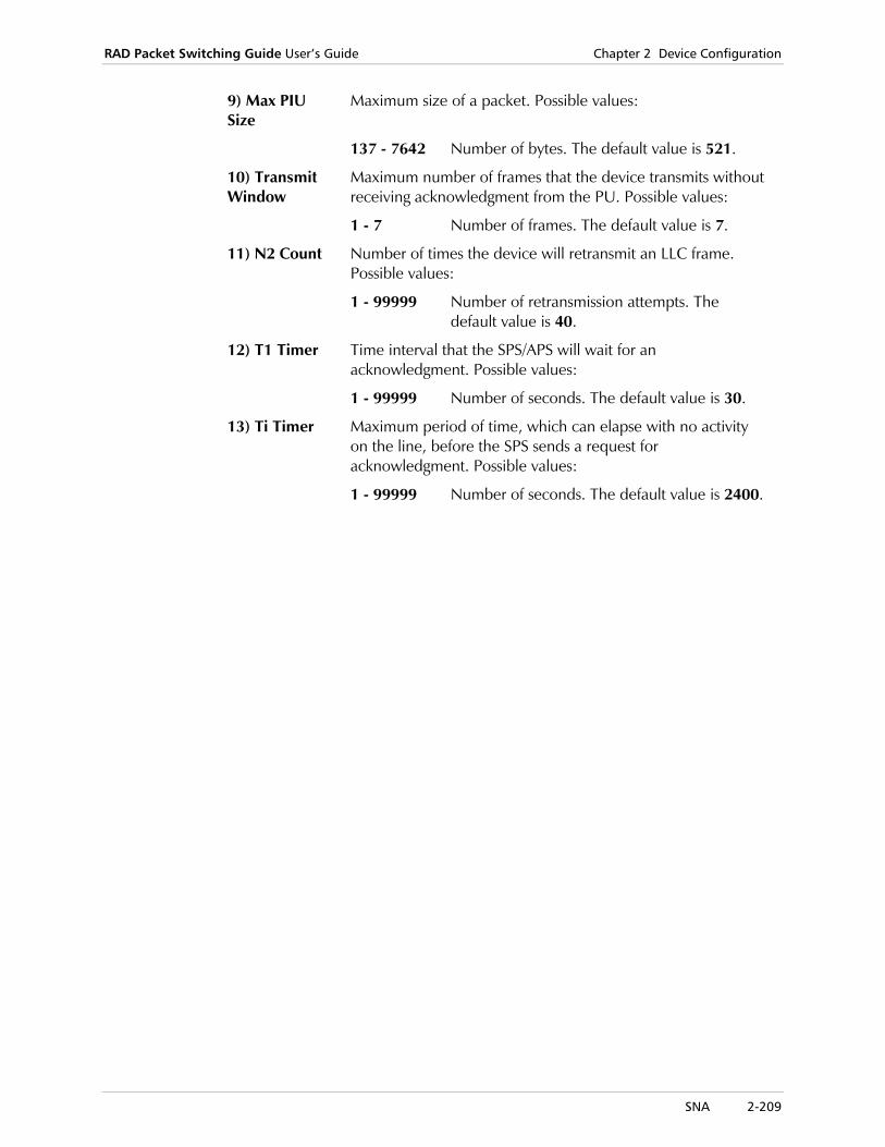
RAD Packet Switching Guide User’s Guide Chapter 2 Device Configuration
SNA 2-209
9) Max PIU Size
Maximum size of a packet. Possible values:
137 - 7642 Number of bytes. The default value is 521.
10) Transmit Window
Maximum number of frames that the device transmits without receiving acknowledgment from the PU. Possible values:
1 - 7 Number of frames. The default value is 7.
11) N2 Count Number of times the device will retransmit an LLC frame. Possible values:
1 - 99999 Number of retransmission attempts. The default value is 40.
12) T1 Timer Time interval that the SPS/APS will wait for an acknowledgment. Possible values:
1 - 99999 Number of seconds. The default value is 30.
13) Ti Timer Maximum period of time, which can elapse with no activity on the line, before the SPS sends a request for acknowledgment. Possible values:
1 - 99999 Number of seconds. The default value is 2400.

Chapter 2 Device Configuration RAD Packet Switching Guide User’s Guide
2-210 SNA

Link Down 3-1
Chapter 3 System Control Functions This chapter explains the available device system control functions, and provides their operating instructions.
SYSTEM CONTROL MENU
---------------------
1) Link down
2) Link up
3) Clear Channel
4) Clear LCN
5) Update date
6) Update time
7) Reset statistics
8) Rearrange NOVRAM
9) Reset
10) Set default configuration
11) Disconnect dial link
12) Enable software upgrade
CR) Exit
Select:
Figure 3-1. System Control Menu
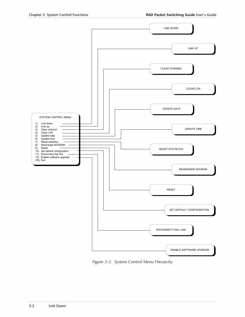
Chapter 3 System Control Functions RAD Packet Switching Guide User’s Guide
3-2 Link Down
SYSTEM CONTROL MENU
1) Link down2) Link up3) Clear channel4) Clear LCN5) Update date6) Update time7) Reset statistics8) Rearrange NOVRAM9) Reset10) Set default configuration11) Disconnect dial link12) Enable software upgradeCR) Exit
LINK UP
LINK DOWN
CLEAR LCN
CLEAR CHANNEL
SET DEFAULT CONFIGURATION
RESET
ENABLE SOFTWARE UPGRADE
DISCONNECT DIAL LINK
REARRANGE NOVRAM
RESET STATISTICS
UPDATE TIME
UPDATE DATE
Figure 3-2. System Control Menu Hierarchy

RAD Packet Switching Guide User’s Guide Chapter 3 System Control Functions
Clear Channel 3-3
3.1 Link Down
Use the Link Down function to stop the traffic through the device channels by logically disconnecting a device link from the X.25 network.
To reconnect, use the LINK UP command.
To disconnect a link
1. In the System Control menu, select 1 (Link Down) and press <Enter>.
2. Select the link number to disconnect and press <Enter>. The link is disconnected and the device displays a confirmation message.
3. Press <Enter> to return to the System Control menu.
3.2 Link Up
Use the Link Up function to enable the normal flow of traffic by logically reconnecting a device link to the X.25 network.
To reconnect a link
1. In the System Control menu, select 2 (Link Up) and press <Enter>.
2. Select the link number to reconnect and press <Enter>. The link is connected and the device displays a confirmation message.
3. Press <Enter> to return to the System Control menu.
3.3 Clear Channel
Use the Clear Channel function to disconnect all sessions established by one of the device asynchronous channels.
To disconnect all sessions on a channel
1. In the System Control menu, select 3 (Clear Channel) and press <Enter>.
2. Select the channel number to disconnect and press <Enter>. The device clears the asynchronous channel and displays a confirmation message.
3. Press <Enter> to return to the System Control menu.
Chapter 3 System Control Functions RAD Packet Switching Guide User’s Guide
3-4 Update Time
3.4 Clear LCN
Use the Clear LCN function to disconnect a logical channel (LCN) established by one of the device links.
To disconnect a logical channel
1. In the System Control menu, select 4 (Clear LCN) and press <Enter>.
2. Type the link number containing the LCN to disconnect and press <Enter>.
3. Type the LCN number and press <Enter>. The device clears the LCN and displays a confirmation message.
4. Press <Enter> to return to the System Control menu.
3.5 Update Date
Use the Update Date function to display and change the date set by the internal clock of the device.
To update the date in the device
1. In the System Control menu, select 5 (Update Date) and press <Enter>.
2. Change the date and press <Enter>. The device returns to the System Control menu.
This function is not applicable for the SPS-2, SPS-3 or APD-2.
3.6 Update Time
Use the Update Time function to display and change the time set by the internal clock of the device.
To update the time in the device
1. In the System Control menu, select 6 (Update Time) and press <Enter>.
2. Change the time and press <Enter>. The device returns to the System Control menu.
This function is not applicable for the SPS-2, SPS-3 or APD-2.
Note
Note
RAD Packet Switching Guide User’s Guide Chapter 3 System Control Functions
Rearrange NOVRAM 3-5
3.7 Reset Statistics
Use the Reset Statistics function to restart the collection of statistical data and to reset the statistics counters.
To reset the statistics counters
1. In the System Control menu, select 7 (Reset Statistics) and press <Enter>. The device displays a confirmation message.
2. Press <Enter> to return to the System Control menu.
3.8 Rearrange NOVRAM
Use the Rearrange NOVRAM function to rearrange the contents of the device non-volatile memory, in order to ensure that all the memory locations are sequentially filled with data.
The device non-volatile memory stores device configuration data and user-supplied information. Each data item is recorded in a contiguous area of the memory. If changes are made on an original data item, some of the memory locations originally occupied by the changed data may no longer be needed. However, these locations cannot be used until the data is rearranged to close the gaps in the allocation of the memory addresses. After rearranging, the gaps are removed and additional space becomes available at the higher memory locations.
This operation is not automatic, because the rearranging involves reading the memory contents, then temporarily storing the data that was read in volatile memory and finally sequentially writing the data back to the non-volatile memory. Since during this process the data is held in the volatile memory where it may be lost if device power fails, it should be carried on under operator’s control.
To rearrange the non-volatile memory of the device
1. In the System Control menu, select 8 (Rearrange NOVRAM) and press <Enter>.
2. When the operation is completed, press <Enter> to return to the System Control menu.
After rearranging, the device must be reset for the changes to take effect.
3. Reset the device by selecting 9 (Reset) on the System Control menu (see Reset on page 3-6), or by pressing the RESET button on the device’s front panel. After reset, the herald message appears again.
Chapter 3 System Control Functions RAD Packet Switching Guide User’s Guide
3-6 Set Default Configuration
3.9 Reset
Use the Reset function to reset the device from the terminal. This operation disrupts the traffic through the device.
To reset the device
1. In the System Control menu, select 9 (Reset) and press <Enter>. The device displays a request for confirmation
2. To accept, type Y and press <Enter>. The device then returns to the System Control menu.
3. To abort, type N and press <Enter>. The device then returns to the System Control menu.
After resetting, the device reloads the last saved configuration. If you changed the parameters used for communication with the DTE on this channel (such as speed, parity, etc.), but did not save the new parameters, the terminal may lose communication with the device after reset. In such a case, change the communication parameters of the terminal accordingly.
3.10 Set Default Configuration
Use the Set Default Configuration function to reload the factory default configuration parameters into the device. For example, this function is recommended when you want to perform device configuration starting from a known baseline.
The device must be reset after this operation.
To reset the device to the default configuration
1. In the System Control menu, select 10 (Set Default Configuration) and press <Enter>.
The device displays a request for confirmation
2. To accept, type Y and press <Enter>. The device then returns to the System Control menu.
3. To abort, type N (or any other character(s) except yes) and press <Enter>. The device then returns to the System Control menu.
4. Reset the device.
Caution

RAD Packet Switching Guide User’s Guide Chapter 3 System Control Functions
Enable Software Upgrade 3-7
3.11 Disconnect Dial Link
Use the Disconnect Dial Link function to disconnect an active dial link on the device.
To disconnect a dial link
1. In the System Control menu, select 11 (Disconnect Dial Link) and press <Enter>.
A list of active links appears.
2. Select the link that you want to disconnect and press <Enter>. The device disconnects the selected link and returns to the System Control menu.
3.12 Enable Software Upgrade
Flash Memory Support The device’s flash memory enables device software update through the terminal. It is not necessary to replace EPROMs in order to upgrade software. Using the Enable Software Upgrade function, you can perform software upgrade by connecting your terminal to a selected port in the device and following the instructions on the screen.
To upgrade the software through the terminal
1. In the System Control menu, select 12 (Enable Software Upgrade) and press <Enter>.
The Enable S/W Upgrade screen appears.
Enable S/W Upgrade
--------------------
1) Async direct connection
2) TFTP
Select:
Figure 3-3. Enable Software Upgrade Screen
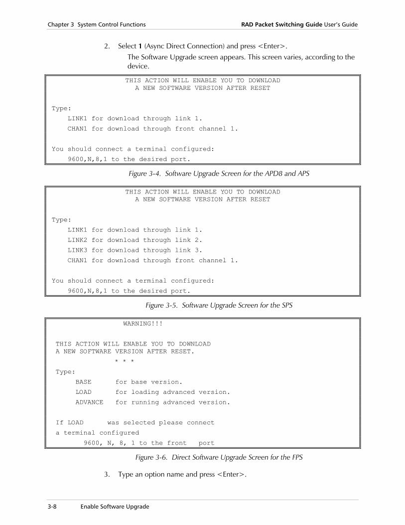
Chapter 3 System Control Functions RAD Packet Switching Guide User’s Guide
3-8 Enable Software Upgrade
2. Select 1 (Async Direct Connection) and press <Enter>. The Software Upgrade screen appears. This screen varies, according to the device.
THIS ACTION WILL ENABLE YOU TO DOWNLOAD A NEW SOFTWARE VERSION AFTER RESET
Type:
LINK1 for download through link 1.
CHAN1 for download through front channel 1.
You should connect a terminal configured:
9600,N,8,1 to the desired port.
Figure 3-4. Software Upgrade Screen for the APD8 and APS
THIS ACTION WILL ENABLE YOU TO DOWNLOAD A NEW SOFTWARE VERSION AFTER RESET
Type:
LINK1 for download through link 1.
LINK2 for download through link 2.
LINK3 for download through link 3.
CHAN1 for download through front channel 1.
You should connect a terminal configured:
9600,N,8,1 to the desired port.
Figure 3-5. Software Upgrade Screen for the SPS
WARNING!!!
THIS ACTION WILL ENABLE YOU TO DOWNLOAD A NEW SOFTWARE VERSION AFTER RESET.
* * *
Type:
BASE for base version.
LOAD for loading advanced version.
ADVANCE for running advanced version.
If LOAD was selected please connect
a terminal configured
9600, N, 8, 1 to the front port
Figure 3-6. Direct Software Upgrade Screen for the FPS
3. Type an option name and press <Enter>.

RAD Packet Switching Guide User’s Guide Chapter 3 System Control Functions
Enable Software Upgrade 3-9
4. Reset the device. After reset, the Software Upgrade System screen appears, displaying options for the speed of the download in bps.
Software Upgrade System
Please select one of the following:
1) 9600 bit/s
2) 19200 bit/s
3) 38400 bit/s
4) 57600 bit/s
5) 115200 bit/s
6) Run the existing software (NO downloading)
Figure 3-7. Software Upgrade System Screen for the APD8, APS or SPS Back Link
Software Upgrade System
Please select one of the following:
1) 9600 bit/s
2) 19200 bit/s
3) 38400 bit/s
4) Run the existing software (NO downloading)
Figure 3-8. Software Upgrade System Screen for the SPS Front Channel No. 1
5. Select the required option and press <Enter>. A message displays the new terminal settings.
The Software Upgrade System screen may also appear automatically after the initial power-up of the packet switching device. In such cases, select Run the existing software (NO downloading) to use the existing device software and prevent RMA or DOA cases. If you access this screen conventionally, you can select any of the displayed upgrade options.
Please change terminal setting To: 1115200, N, 8, LINK1 And start to download new software
6. Press <Enter> to proceed. The TST LED turns on for several seconds. Dots then appear on the terminal screen.
During the download, the NOVRAM updates the previously defined parameters, so that they are compatible with the new software version. The device’s synchronous link LEDs indicate this action by a continuous running indication from link to link.
Note
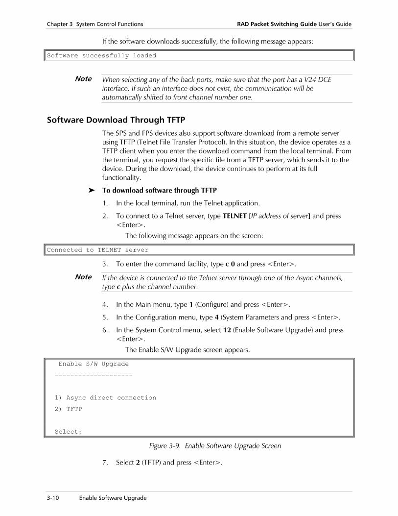
Chapter 3 System Control Functions RAD Packet Switching Guide User’s Guide
3-10 Enable Software Upgrade
If the software downloads successfully, the following message appears:
Software successfully loaded
When selecting any of the back ports, make sure that the port has a V24 DCE interface. If such an interface does not exist, the communication will be automatically shifted to front channel number one.
Software Download Through TFTP The SPS and FPS devices also support software download from a remote server using TFTP (Telnet File Transfer Protocol). In this situation, the device operates as a TFTP client when you enter the download command from the local terminal. From the terminal, you request the specific file from a TFTP server, which sends it to the device. During the download, the device continues to perform at its full functionality.
To download software through TFTP
1. In the local terminal, run the Telnet application.
2. To connect to a Telnet server, type TELNET [IP address of server] and press <Enter>.
The following message appears on the screen:
Connected to TELNET server
3. To enter the command facility, type c 0 and press <Enter>.
If the device is connected to the Telnet server through one of the Async channels, type c plus the channel number.
4. In the Main menu, type 1 (Configure) and press <Enter>.
5. In the Configuration menu, type 4 (System Parameters and press <Enter>.
6. In the System Control menu, select 12 (Enable Software Upgrade) and press <Enter>.
The Enable S/W Upgrade screen appears.
Enable S/W Upgrade
--------------------
1) Async direct connection
2) TFTP
Select:
Figure 3-9. Enable Software Upgrade Screen
7. Select 2 (TFTP) and press <Enter>.
Note
Note
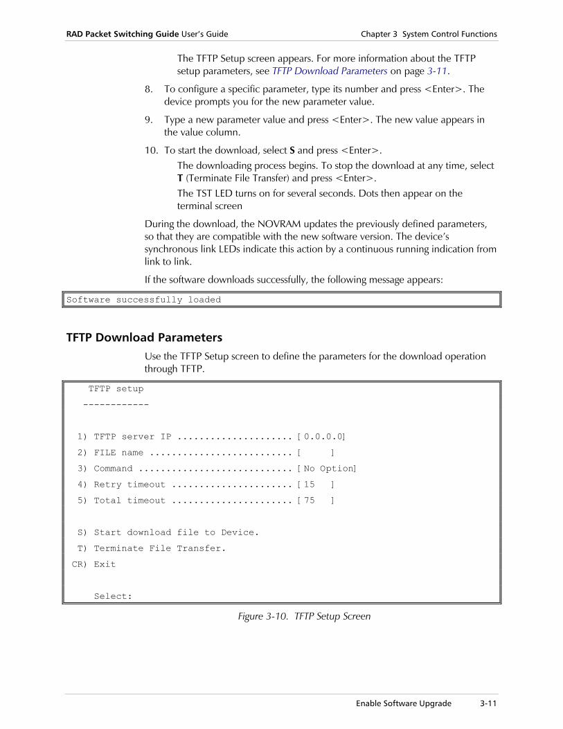
RAD Packet Switching Guide User’s Guide Chapter 3 System Control Functions
Enable Software Upgrade 3-11
The TFTP Setup screen appears. For more information about the TFTP setup parameters, see TFTP Download Parameters on page 3-11.
8. To configure a specific parameter, type its number and press <Enter>. The device prompts you for the new parameter value.
9. Type a new parameter value and press <Enter>. The new value appears in the value column.
10. To start the download, select S and press <Enter>. The downloading process begins. To stop the download at any time, select T (Terminate File Transfer) and press <Enter>. The TST LED turns on for several seconds. Dots then appear on the terminal screen
During the download, the NOVRAM updates the previously defined parameters, so that they are compatible with the new software version. The device’s synchronous link LEDs indicate this action by a continuous running indication from link to link.
If the software downloads successfully, the following message appears:
Software successfully loaded
TFTP Download Parameters Use the TFTP Setup screen to define the parameters for the download operation through TFTP.
TFTP setup
------------
1) TFTP server IP ..................... [0.0.0.0]
2) FILE name .......................... [ ]
3) Command ............................ [No Option]
4) Retry timeout ...................... [15 ]
5) Total timeout ...................... [75 ]
S) Start download file to Device.
T) Terminate File Transfer.
CR) Exit
Select:
Figure 3-10. TFTP Setup Screen
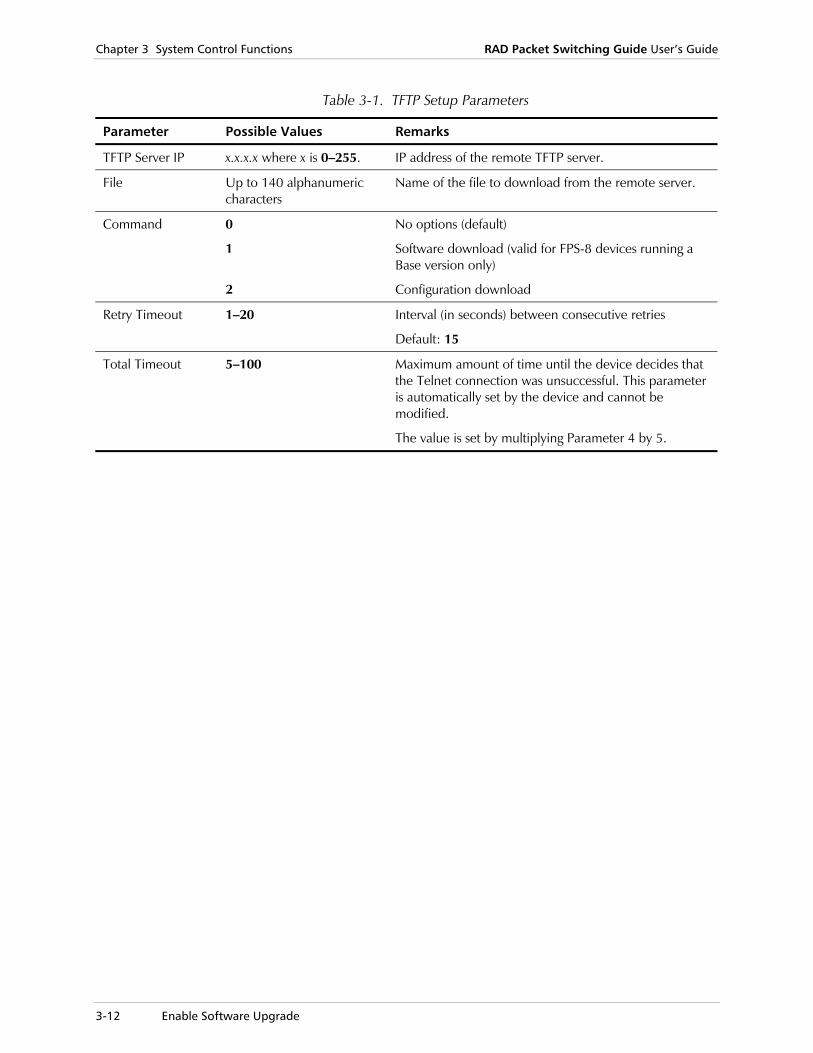
Chapter 3 System Control Functions RAD Packet Switching Guide User’s Guide
3-12 Enable Software Upgrade
Table 3-1. TFTP Setup Parameters
Parameter Possible Values Remarks
TFTP Server IP x.x.x.x where x is 0–255. IP address of the remote TFTP server.
File Up to 140 alphanumeric characters
Name of the file to download from the remote server.
Command 0
1
2
No options (default)
Software download (valid for FPS-8 devices running a Base version only)
Configuration download
Retry Timeout 1–20 Interval (in seconds) between consecutive retries
Default: 15
Total Timeout 5–100 Maximum amount of time until the device decides that the Telnet connection was unsuccessful. This parameter is automatically set by the device and cannot be modified.
The value is set by multiplying Parameter 4 by 5.

Packet-Switched Call Processing 4-1
Chapter 4 Calling and Control Procedures This chapter explains:
• How to set up data calls through X.25 packet switched networks
• How to use synchronous or asynchronous data terminal equipment connected to one of the device channels
• How to check and update, where necessary, the PAD parameters in order to initiate calls. See Chapter 2, Device Configuration, for a description of the PAD parameters plus instructions for configuring the device using its command facility.
• The PAD commands supported by the device.
• The Telnet Control commands supported by the device.
The information in this chapter is intended for persons who are already knowledgeable of the basic concepts of X.25/FR packet switched data networks, PAD commands and PAD/FRAD parameters.
The information in this chapter is not intended to serve as a comprehensive guide to the use of the services provided by the X.25 network to which you subscribed. For more information, refer to your subscription conditions, and to the operating instructions that may have been prepared by your data carrier company or by your system administrator.
Note
Chapter 4 Calling and Control Procedures RAD Packet Switching Guide User’s Guide
4-2 Packet-Switched Call Processing
4.1 Packet-Switched Call Processing
This section provides background information for using the device PAD characteristics efficiently. These characteristics apply to each channel, independently of the operations performed by the other channels.
Definitions
Channel PAD States
The channel PAD has two main states:
Free Channel PAD is free and available for the user.
Engaged Channel PAD is processing another call. For example, it connects or disconnects another call.
PAD Async Channel Modes
The PAD async channel can be in one of the following operating modes:
Data transfer mode
Channel transparently transfers the data characters received from the connected DTE to the X.25 network, and the data characters received from the network to the DTE. If the DTE does not transmit any characters, the channel PAD transmits a continuous sequence of “1” to the user’s DTE.
You and/or the X.25 network can instruct the channel to escape from the data transfer mode and enter the waiting-for-command mode (provided the channel is free). Usually, this is achieved by inserting a PAD recall character (see Profile Configuration, parameter 1) in the data stream.
Waiting-for-command mode
Temporary state that starts when the channel receives a PAD recall character and ends with the reception of the next character. The response of the PAD depends on the character that follows the PAD recall character:
• If the next character is a second PAD recall character, the channel returns to the data transfer mode and transmits thischaracter. This arrangement enables end-to-end transmission of the PAD recall character (by repeating it twice).
• If the next character is a carriage return, the channel returns to the data transfer mode.
Any character except a carriage return transfers the channel PAD to the command mode.
RAD Packet Switching Guide User’s Guide Chapter 4 Calling and Control Procedures
Packet-Switched Call Processing 4-3
Command mode Channel intercepts all the characters received from the DTE, and tries to interpret them as PAD commands.
• If the characters cannot be interpreted as valid commands, the channel sends an error message, returns to the command mode and waits for a valid command.
• If the received string of characters includes only the command delimiter (carriage return or +) without any preceding characters, the channel exits the command mode and returns to its previous mode.
Link States
A data call is performed by establishing a virtual circuit (link) between the terminals. Four states are defined in relation to this action:
• Link setup
• Information transfer: can include three sub-states:
Normal data transfer
Resetting (clearing of all the data buffers along the link, usually after receipt of an invalid frame, and then return to normal data transfer)
Reinitialization (set up the link again).
• Link disconnection
• Link disconnected.
DTE Interface States
If the “H/W signal” option from the Channel Configuration screen (parameter 14, option 1) is active, the PAD checks the state of a hardware interface control line. The channel monitors the state of the RTS line in the channel connector and determines if the user DTE is connected and operating (RTS line activated).
If your specific application requires the use of another line as an indication of DTE operation, use an appropriately wired cable to connect the additional line to the RTS line in the device channel connector.
Note
Chapter 4 Calling and Control Procedures RAD Packet Switching Guide User’s Guide
4-4 Packet-Switched Call Processing
Outline of Manual Call Initiation Procedure This section explains the basic procedure for manually initiating a call (including mnemonic calls) from the local user’s DTE.
1. The local DTE initiates a call by supplying a free PAD channel with the parameters required to initiate a call. The call parameters must always include the destination address. Optionally, the parameters may include a destination subaddress, a request for special services (called ITU facilities), and up to 128 characters of user data.
The data required to initiate a call can also be retrieved automatically from the memory (see Mnemonic Call on page 4-13).
2. Following the call request, the PAD channel checks the validity of the call data. If the call data is valid and complete, the channel starts the call setup procedure. This procedure may include a delay, depending on the traffic load. If the setup procedure is successful, the channel sends a COM message to
the DTE, indicating that data transfer can start.
If the setup procedure fails, the PAD receives a clear message from the X.25 network. The message can be followed by a cause code that indicates the reason. This code can be sent to the user, provided the channel PAD is programmed to transfer such messages to the user's DTE.
3. After the COM message, the channel enters the data transfer mode, enabling the DTE to transfer data transparently.
4. During the data call, the user’s DTE can request service again from the PAD by sending the PAD recall character, followed by a PAD command. The PAD stops data transfer and executes the command. To exit the command mode and return to the data transfer mode, the DTE must send a carriage return (without any preceding character).
5. During the data call, the user’s DTE can set up a new call to another destination without disconnecting the current call. Since each channel can support up to four simultaneous sessions (independent data calls from the same DTE), the first call made by a DTE is automatically defined as session No. 1.
The new call is performed by: Recalling the PAD as described above.
Selecting a free session number. At this point, the user’s DTE is disconnected by the device from the original call.
For user’s convenience, if the current session number is not 1, the PAD prompt is modified to include the session number before the PAD prompt character.
Performing the regular call set up procedure.

RAD Packet Switching Guide User’s Guide Chapter 4 Calling and Control Procedures
Packet-Switched Call Processing 4-5
6. At any time, the user can return to a previous session.
An inactive session continues to accept received data until its allocated buffers (8) fill up. When this occurs, the remote DTE receives a flow control OFF command.
When the user returns to a session, data flow is enabled again after the local user receives the data stored in the buffers.
7. To disconnect the current call, the DTE uses the procedure described above to recall the PAD, and then sends a clear request. After the clear request is processed and fulfilled, the PAD sends an appropriate message to the DTE.
Call Reception Process • When the X.25 network (or another PAD that can communicate with the
device) has data to be transferred to one of the local DTEs, it signals the PAD, and transfers the data transfer parameters to the PAD.
• The PAD signals the attached user’s DTE that a call arrived. If the local user’s DTE is turned on and can accept the data, the PAD returns an indication to the X.25 network that the call will be accepted, and then enters the data transfer mode.
• After the data transfer mode is entered, the data call proceeds as described above for a locally initiated call.
Autocall Initiation Procedure The autocall function provides a device with a fully automated procedure for initiating a connection to a destination. The device will automatically initiate the call either when the device is turned on, or when the user’s DTE is turned on (as indicated by the state of the RTS line in the channel connector), provided the X.25 link operates is synchronized.
The autocall-specific data required to set up the call is defined during channel configuration, and includes:
• The legal X.28 connect command line, specified by a Call ID
• The number of call initiation retries and the interval between consecutive retries
• An alternate destination address, to be used if the call to the first destination failed. This entry is optional
• An optional sequence of X.28 commands (alias) that is automatically executed when the call is set up.

Chapter 4 Calling and Control Procedures RAD Packet Switching Guide User’s Guide
4-6 Packet-Switched Call Processing
The autocall initiation procedure operates as follows:
1. When the device is turned on and its X.25 link synchronized, it searches its database for channels with autocall requests.
2. The autocall requests are then processed sequentially. For each autocall channel, the device checks whether the connected DTE is active. If it is, the corresponding PAD starts a regular call setup process in accordance with the channel configuration data. If the call is completed, the PAD executes a specified alias, if defined, and then enters the data transfer mode.
3. If the first call request fails, the PAD repeats the call request at the specified intervals. If the call cannot be completed up to the last retry, the PAD automatically starts a new call setup sequence using the alternate destination.
4. If a user’s DTE connected to an autocall channel is not operating when the device is turned on, the PAD continues to monitor the DTE state. When the DTE is turned on, the call setup process is automatically initiated.
The autocall function can also be activated manually in the following cases:
• The original call was disconnected.
• The call set up process failed (neither of the two specified destinations could be reached within the specified number of retries).
To activate the autocall function again, press the <Enter> key of the user’s DTE. The PAD will then restart the call setup process on this channel.
Call Initiation on PVC Call initiation on a channel configured for PVC operation is automatically performed by the device when it is turned on and its X.25 link synchronizes, or when the user’s DTE is turned on after the device is already operating. The device then signals the X.25 network switch to set up a permanent call, in accordance with the destination requested at subscription time.
If a permanent call is disconnected (because of a network problem), the X.25 switch can be signaled to connect the call again by pressing the <Enter> key of the corresponding user’s DTE.

RAD Packet Switching Guide User’s Guide Chapter 4 Calling and Control Procedures
Packet-Switched Call Processing 4-7
Local Calls The device supports local calls, such as calls between the users connected to two different asynchronous channels.
The device interprets any address of up to two digits as a local address. The value of two digits is the default value of the system parameter Inner Communication length (see System Parameters Configuration in Chapter 2) and can be changed if required. Therefore, the device will not send call requests with addresses of one or two digits through one of the links, but will attempt to connect the call to a local channel. If the address includes more digits, the device will send a call request through one of the links.
A local call is similar to a call to a remote user, except that the device makes the connection internally, without using the X.25 link and/or requiring any service from the X.25 network.
For local call connection, the address of a local user is its subaddress (the default value of subaddress 1 is the physical channel number).
For STMs, the subaddresses of the channels must be defined. Their default values are 0.
Note

Chapter 4 Calling and Control Procedures RAD Packet Switching Guide User’s Guide
4-8 Calling Procedures
4.2 Calling Procedures
This section provides instructions for performing the following activities related to the execution of packet-switched data calls through the device channels:
• Setting up and disconnecting data calls using manual and mnemonic call setup procedures. The use of autocall or permanent virtual circuits is also covered.
• Receiving data calls
• Using the multiple session feature
• Reading and updating the PAD parameters values used on your channel.
The device includes a help function that displays the list of PAD commands (including the X.28 commands and the proprietary RAD commands), and presents concise explanations on the purpose and format of each command. To open the Help facility, type HELP or H after the PAD prompt.
Manual Call Initiation Procedure • The call initiation command (CON) has the following fields:
CON + <Space>
PAD call setup command.
Destination address
Address of the called DTE (up to 15 digits). This field is mandatory.
Destination subaddress
One or two digits. This field is optional.
ITUT facility block
Optional field.
Call data Optional field.
<Enter> or <+>
Ends the call command and instructs the PAD to interpret and execute the command.
The minimum data that must be sent is the destination address.
Format of Manual Call Initiation Command
The format of the manual call initiation command is as follows:
CON [facility block] destination address [subaddress /subaddress in
The command fields are explained below.
Note
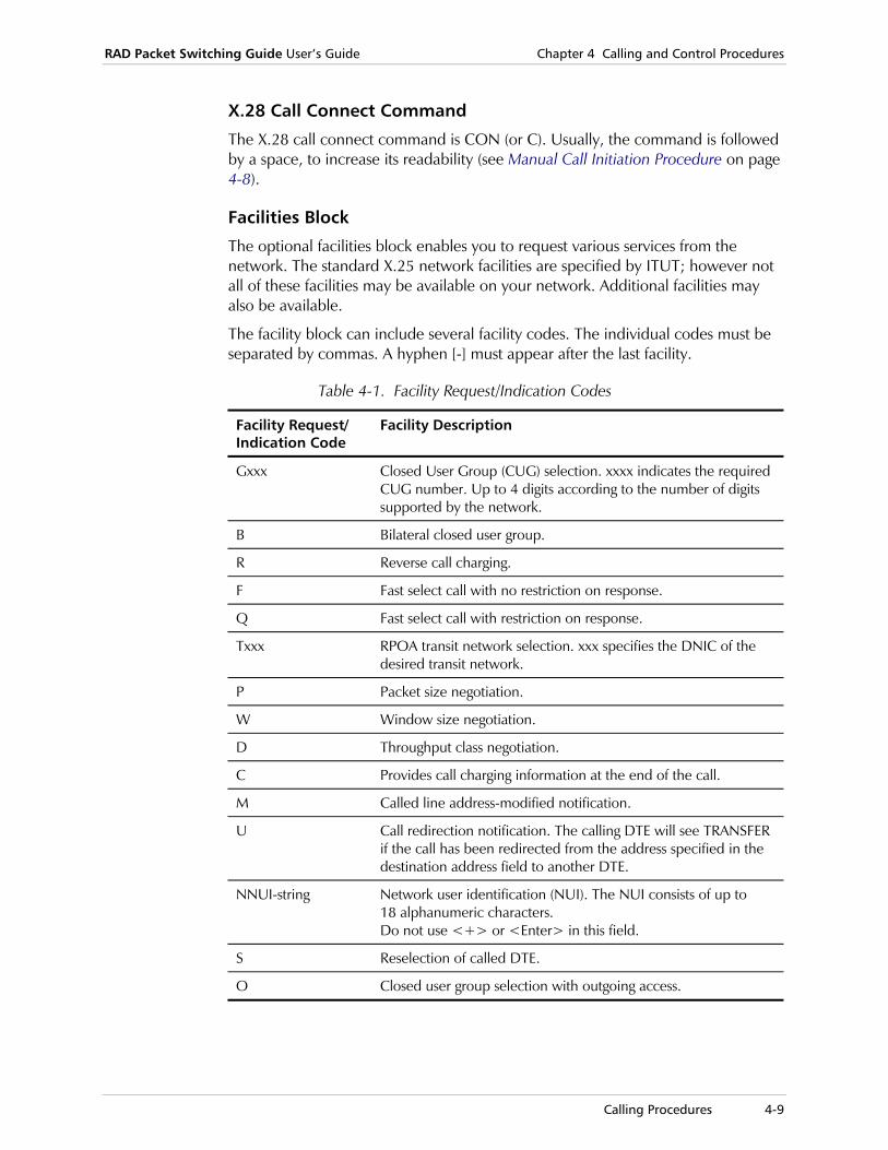
RAD Packet Switching Guide User’s Guide Chapter 4 Calling and Control Procedures
Calling Procedures 4-9
X.28 Call Connect Command
The X.28 call connect command is CON (or C). Usually, the command is followed by a space, to increase its readability (see Manual Call Initiation Procedure on page 4-8).
Facilities Block
The optional facilities block enables you to request various services from the network. The standard X.25 network facilities are specified by ITUT; however not all of these facilities may be available on your network. Additional facilities may also be available.
The facility block can include several facility codes. The individual codes must be separated by commas. A hyphen [-] must appear after the last facility.
Table 4-1. Facility Request/Indication Codes
Facility Request/ Indication Code
Facility Description
Gxxx Closed User Group (CUG) selection. xxxx indicates the required CUG number. Up to 4 digits according to the number of digits supported by the network.
B Bilateral closed user group.
R Reverse call charging.
F Fast select call with no restriction on response.
Q Fast select call with restriction on response.
Txxx RPOA transit network selection. xxx specifies the DNIC of the desired transit network.
P Packet size negotiation.
W Window size negotiation.
D Throughput class negotiation.
C Provides call charging information at the end of the call.
M Called line address-modified notification.
U Call redirection notification. The calling DTE will see TRANSFER if the call has been redirected from the address specified in the destination address field to another DTE.
NNUI-string Network user identification (NUI). The NUI consists of up to 18 alphanumeric characters. Do not use <+> or <Enter> in this field.
S Reselection of called DTE.
O Closed user group selection with outgoing access.
Chapter 4 Calling and Control Procedures RAD Packet Switching Guide User’s Guide
4-10 Calling Procedures
Destination Address
The destination address for a call to a remote subscriber is its X.25 directory number, and the destination address of another user connected to the same device is the channel subaddress. This field is mandatory. By default, the channel subaddress is equal to the channel number (except for STMs, where the channel subaddress must be defined through the Channel Configuration menu).
The minimum length of the destination address field is 1 digit, and the maximum length is 15 digits. Do not use <+> or <Enter> in the destination address field.
The device PAD supports the ITUT Rec. X.121 addressing scheme. The X.25 network directory numbers specified by the ITU Rec. X.121 numbering plan include three sections:
International prefix
In some networks, the first digit of the address must indicate that the called address is outside the calling DTE network.
DNIC The next four digits specify the Data Network Identification Code (DNIC), a code that uniquely identifies the public data network to which the destination DTE is attached.
NTN The next digits (up to ten) form the Network Terminal Number (NTN). The NTN is assigned by the network administration in accordance with its needs.
Subaddress
This field indicates a subaddress, which will be entered in the called address field. If the subaddress exists, it must be added immediately after the destination address to create one complete number. The complete number composed from the address and the subaddress contains up to 15 digits.
Either a subaddress field is entered or a /subaddress in user data filed is entered.
The subaddress is an optional field.
Subaddress in User Data
This field indicates that the subaddress is used in the user data field and not in the called address field. This field is optional.
When this field is transmitted to the destination address, leading zeros are added according to parameter 113 (Subaddress in CUD) of the selected Profile configuration (see Profile Configuration in Chapter 2).
When receiving a call request packet, if the ‘Subaddress in Call User Data’ bit is set in the ‘In call options’ parameter of the X.25 link configuration (see X.25 Link Parameters in Chapter 2), then the subaddress is reconstructed from the User Data field and not from the Called Address. When the above bit is set at the destination device, the sending device must use the subaddress at the User Data field.
Either the /subaddress in user data field is entered or the subaddress field is entered.
If this field is used in a manual call command, it starts with /, followed by the subaddress number.
RAD Packet Switching Guide User’s Guide Chapter 4 Calling and Control Procedures
Calling Procedures 4-11
Call User Data Field
If this subfield is used in a manual call command, it starts with D, followed by up to 16 characters. D indicates that the following characters are text sent by the caller to the other party, together with the call request.
When using the fast select facility, the data field may contain up to 128 characters. This field is optional.
Making a Manual Data Call This section explains the procedure used to make a data call using the manual call initiation command.
If you do not specify a session number, the call is formed on the last selected session. By default, the channel PAD selects session 1. For instructions on the use of the multiple session feature, see Use of Multiple Sessions on page 4-17.
Recalling the PAD
If the channel PAD is in the command mode, the PAD prompt * appears on the monitor of your DTE.
It is possible to define a different prompt character by changing the X.28 Prompt parameter. For more information, see System Parameters Configuration in Chapter 2.
To recall the PAD if it is not in the command mode
1. Press <Ctrl>+<P>. The channel PAD enters the command mode, and sends the PAD prompt (*) to your DTE.
2. To check that the PAD is available, type STAT and press <Enter>. If a call is active, or the PAD is processing a call termination or a call
initiation request, ENG (engaged) appears on the screen
If you try to initiate a call when another call is active, it will be rejected and an ERR message appears. If you want to start a new call without disconnecting the ongoing call, you must open an additional session, or select another session.
If the PAD is free, the FREE message appears. You can now continue.
Note

Chapter 4 Calling and Control Procedures RAD Packet Switching Guide User’s Guide
4-12 Calling Procedures
Manual Call Initiation Examples
1. Type the call initiation command. A few examples of call initiation commands are shown below: Basic command to call the X.25
37478712 with subaddress 34. The address and the subaddress joined together form the called address field: C 3747871234 <CR>
Command with the subaddress in the user data field: C 12345678/123 <CR>
Command with user data field: C 3747871234 DGood Morning <CR>
Command with the subaddress and other data in the user data field: C 12345678/90 DHello there <CR>
Command with facilities block: C G12,R,N5886512R-3747871234DGood Morning <CR> G12 requests a call within CUG 12. R requests reverse charges. N5886512R is an example of NUI utilization.
Command to call the user connected to channel 4 of this device: C 4<CR> or CO4 <CR>
Command with window size negotiation: C W - 1234567890
2. Wait for call processing. If the call is rejected, CLR appears on the screen, possibly followed by a code from the network explaining why. Try calling again when the problem is corrected. A CLR ERR message means network is not in “ready” condition.
3. When the call is accepted and established, COM appears on your terminal. Optionally, information about the called DTE and the facilities used for this call also appears. Go on with your application.
Call Termination
1. Press <Ctrl>+<P> to enter the PAD command mode. When the PAD prompt appears, data transfer stops.
2. Type CLR and press <Enter> to terminate the call.
To instruct the remote PAD to clear the call, type ICLR and press <Enter>.
3. Wait for command processing. When the X.25 network confirms call termination, CLR CONF appears on your terminal, followed by the PAD prompt.
Note

RAD Packet Switching Guide User’s Guide Chapter 4 Calling and Control Procedures
Calling Procedures 4-13
Accepting a Call When a call is received, COM appears on your terminal. Optionally, additional information about the calling DTE and the facilities used for this call, also appear.
Mnemonic Call To initiate a call faster, you can use a mnemonic, which represents the parameters that normally must be actually typed to initiate a call. When the mnemonic call connect command format is used, the device retrieves the required information from the PAD memory, and inserts it in the proper command fields.
Mnemonic Format
The format of the mnemonic call initiation command is as follows:
CON [mnemonic] or C [mnemonic]
X.28 Mnemonic Call Command
CON (or C), usually followed by a space.
Mnemonic Code String used to send the call initiation command. The call initiation information in this string is defined in the Call ID Configuration screen (see Call ID Configuration in Chapter 2).
Preparation of a New Mnemonic Code
To prepare a new mnemonic code
1. In the Configuration menu, select 6 (Call ID) and press <Enter>. The Call ID Configuration menu appears.
2. Select 1 (Add Call ID) and press <Enter>. A list of existing Call IDs appears.
3. Type a number for the new Call ID (1 - 200) and press <Enter>. The Call ID n Configuration screen appears.
4. To define the mnemonic code, select 1 (Mnemonic) and press <Enter>.
5. Type the code (up to eight alphanumeric characters) and press <Enter>.
6. To define the Command line, select 2 (Command line) and press <Enter>.
7. Type the X.28 connect command line and press <Enter>.
8. Type S and press <Enter> to save the new configuration.
9. Press <Enter> several times to return to the Main menu.
10. Select 5 (Logout) and press <Enter>.

Chapter 4 Calling and Control Procedures RAD Packet Switching Guide User’s Guide
4-14 Calling Procedures
Making a Mnemonic Call
When the mnemonic option is programmed, the information required to initiate a PAD call is automatically sent using the preconfigured parameters.
1. If necessary, press <Ctrl>+<P> to enter the PAD command mode. To check that the PAD is free, type STAT and press <Enter>.
2. Type the mnemonic call initiation commands and press <Enter>. For example, you could use the following command to call your bank:
C bank When the call is accepted and established, COM appears on your terminal. Continue working with your application.
Call Termination
1. Press <Ctrl>+<P> to enter the PAD command mode. When the PAD prompt appears, data transfer stops.
2. Type CLR and press <Enter> to terminate the call.
To instruct the remote PAD to clear the call, type ICLR and press <Enter>.
3. Wait for command processing. When the X.25 network confirms call termination, CLR CONF appears on your terminal, followed by the PAD prompt.
Autocall Calls Autocall calls are set up automatically when the device channel interface senses that an operating DTE is connected, and the X.25 link is synchronized.
The autocall function parameters are defined in the Channel Configuration screen (see Channel Configuration in Chapter 2).
Preparing the Autocall Information
To prepare the autocall information:
1. In the Configuration menu, select 1 (Channel) and press <Enter>. The Channel Configuration menu appears.
2. In the Channel Configuration menu, select 3 (Update channel) and press <Enter>.
A list of channels and their corresponding protocol types appears.
3. Type the number of the channel you want and press <Enter>. The Channel n Configuration screen appears.
4. Select 5 (AutoCall ID) and press <Enter>. Type a Call ID number (1 - 200) that is already stored in the device and press <Enter>.
Note
RAD Packet Switching Guide User’s Guide Chapter 4 Calling and Control Procedures
Calling Procedures 4-15
5. If you want the device to setup a call to an alternate destination, select 6 (Alternate AutoCall ID). Type a Call ID number (1 - 200) that is already stored in the device and press <Enter>.
If you have only one destination to call, type 0 and press <Enter>.
6. Select 7 (Autocall retries) and press <Enter>. Type the number of call retries (1 - 255) in case the call setup request is rejected by a “number busy” message, and press <Enter>.
7. Select 8 (Autocall retry interval) and press <Enter>. Type the number of seconds (1 - 255) between consecutive retries and press <Enter>.
8. Select 14 (Options) and press <Enter>. For autocall after clear, including reset, type 2 and press <Enter>.
For autocall after <Enter>, type 4 and press <Enter>.
For autocall where RTS is set, type 32 and press <Enter>.
You may also enter any combination of these values.
9. Type S and press <Enter> to save the new configuration.
10. Press <Enter> several times to return to the Main menu.
Autocall Set-up Process
The connection of the autocall is initiated automatically according to the defined autocall option(s) (Channel Configuration screen, parameter 14).
When the call is established, COM appears on your terminal. Continue working with your application.
If the call cannot be established, a clear cause message appears on your terminal. When the problem that prevented the call setup is corrected, press <Enter> or reset your DTE.
Call Termination
1. Press <Ctrl>+<P> to enter the PAD command mode. When the PAD prompt appears, data transfer stops.
2. Type CLR and press <Enter> to terminate the call.
To instruct the remote PAD to clear the call, type ICLR and press <Enter>.
3. Wait for command processing. When the X.25 network confirms call termination, CLR CONF appears on your terminal, followed by the PAD prompt.
Note

Chapter 4 Calling and Control Procedures RAD Packet Switching Guide User’s Guide
4-16 Calling Procedures
Calls on Permanent Virtual Circuits Calls on permanent virtual circuits (PVC) are set up automatically when the device channel interface detects that an operating DTE is connected, and the X.25 link is synchronized.
Preparing the PVC Configuration Data
To prepare the PVC configuration
1. In the Configuration menu, select 5 (PVC) and press <Enter>. The PVC Configuration menu appears.
2. Select 1 (Add PVC) and press <Enter>. A list of existing PVCs appears.
3. Type a number for the new PVC (1 - 200) and press <Enter>. The New PVC Configuration screen appears.
4. Select 1 (Local) for Local PVC. The Local PVC n Configuration screen appears, according to the selection. The PVC number (n) is identified in the screen title. For a description of the parameters in each screen, see Local PVC Parameters in Chapter 2.
5. Select 1 (Channel number) and press <Enter>. Type the number of the device channel that will be connected through the PVC, and press <Enter>.
6. Select 2 (Link ID) and press <Enter>. Type the number of the device link that will be used to establish the PVC, and press <Enter>.
7. Select 3 (LCN) and press <Enter>. Type the number of the logical channel (0 - 255) that will be used to establish the PVC, and press <Enter>.
8. Type S and press <Enter> to save the new configuration.
9. Press <Enter> several times to return to the Main menu.
10. Select 2 (System Control). The System Control menu appears.
11. Select 9 (Reset) and press <Enter>. The device requests confirmation. Type y and press <Enter>. The device is reset. After resetting is complete, the herald message appears on the terminal.
PVC Set-up Process
When you turn your DTE on, the PAD serving the channel you are connected to automatically signals the X.25 network to connect the permanent virtual circuit.
When the circuit is established, COM appears on your terminal. Continue working with your application.
If the call cannot be established, a clear cause message appears on your terminal. When the problem that prevented the PVC setup is corrected, press <Enter> or reset your DTE.
A permanent virtual circuit cannot be disconnected as long as your DTE is active.
RAD Packet Switching Guide User’s Guide Chapter 4 Calling and Control Procedures
Calling Procedures 4-17
Use of Multiple Sessions RAD Packet Switching devices support the connection of multiple sessions to different destinations at the same time.
Starting a New Session
To start a new session to another destination
1. If an active call is handled by the current session, press <Ctrl>+<P> to enter the PAD command mode.
2. Type SES # and press <Enter>. # indicates the number of the new session (1 - 4)
The PAD prompt reappears. If the new session number is not 1, the session number (2, 3, or 4) appears to the left of the PAD prompt (separated by one space).
You can perform all applicable procedures on the new session. The call handled by the previous session is not disconnected, but eventually the buffers allocated for the storage of received data on that call, fill up. The flow control function then stops the reception of further data.
Returning to a Previous Session
Use the above procedure to return to a call from a session you previously left.
If you return to SES 1, no session number appears on the screen (only for sessions 2, 3 or 4).
Note

Chapter 4 Calling and Control Procedures RAD Packet Switching Guide User’s Guide
4-18 PAD Control
4.3 PAD Control
Command Editing Procedures
Command Editing Characters
Use the following commands, called standard editing characters, to prepare and edit PAD commands. However, if your system administrator changed the profile, other characters may be used in the various commands (see Profile Configuration in Chapter 2).
<Enter> or <CR>
Press this key to indicate the “end-of-command”. This command is immediately sent and executed.
If you press <Enter> at the PAD prompt (without typing any characters), the PAD exits the command mode and returns to data transfer.
<Del> Press this key to delete the character to the left of the screen cursor in the command line.
<DLE> or <Ctrl>+<P>
Press the <DLE> key to interrupt data transmission and wait forthe PAD command. If your keyboard does not have a <DLE> key, press <Ctrl>+<P>.
The <Ctrl>+<P> combination generates the default PAD recall character.
<Ctrl>+<X> Press these keys to delete the entire command line.
<Ctrl>+<R> Press these keys to display the last line.
+ Alternative “end-of-command” character. Press this key to send and execute the command immediately.
! Press this key to redisplay the last command on the next line (RAD proprietary editing function). You can edit the command on the screen, to form a new command.
Typing PAD Commands
When the PAD is ready to receive PAD commands, it sends the PAD prompt to the DTE. The default PAD prompt is the asterisk *. The prompt appears when the DTE is first connected to a device channel (or turned on).
If you want to send a PAD command, but do not see the asterisk although no application is active, press <Ctrl>+<P> (or whatever PAD recall character is used in your system).
Commands are case-insensitive. You can use upper and lower case characters. Spaces are ignored; insert spaces only to improve readability of the command.
Note

RAD Packet Switching Guide User’s Guide Chapter 4 Calling and Control Procedures
PAD Control 4-19
Sending a Command
To send a command
1. If the PAD prompt appears, type the command and check it.
2. When you are sure the command is correct, press <Enter> or <+>. The command is sent and interpreted by the channel PAD. If an error is detected in the command, the PAD stops, sends the ERR message to the DTE and then returns to the command mode.
The characters and/or character strings that the PAD returns to the user DTE are called “PAD service signals”.
Stopping Data Transfer
To Stop Data Transfer
• Press CTRL P or the <DLE> key.
The PAD of the corresponding device channel sends the characters currently stored in the buffers allocated to the current session (up to the PAD recall command), then stops data transfer and enters the command mode. The PAD then tries to interpret any characters you type up to <Enter> or <+> as a command. When a <+> or <Enter> without any preceding character is detected,
the PAD returns to the data transfer mode.
In the data transfer mode, the PAD transmits all the characters received from the DTE until it again detects a PAD recall character.
PAD Command Set The PAD commands supported by the device perform the following functions:
• Establishment and clearing of virtual calls
• Resetting of a virtual call
• Sending of an interrupt request
• Selection of another session
• Selection of a PAD profile
• Selection of individual PAD parameter values
• Reading of the current PAD parameter values
• Reading of the current PAD status
• Displaying the help function.
Note
Chapter 4 Calling and Control Procedures RAD Packet Switching Guide User’s Guide
4-20 PAD Control
PAD Service Signals
In response to the PAD commands, the device PAD can return PAD service signals (Profile n Configuration screen, parameter 6). If enabled, the PAD service signals provide the following information:
• Acknowledgement of reception of PAD commands
• Call progress indications
• PAD operation indications.
Listing of PAD Command Set
The device PAD supports the full set of commands specified in ITU Rec. X.28, and additional RAD proprietary commands.
• Table 4-2 provides a concise summary of the ITU Rec. X.28 command set.
• Table 4-3 provides a concise summary of the RAD proprietary command set.
• Table 4-5 lists the PAD service signals specified in ITU Rec. X.28, which are sent by the X.25 network in response to these commands, and are displayed on the DTE to control the PAD.
• The term “format effector” is a sequence of two characters, CR and LF (carriage return and line feed), followed by several padding characters. The number of padding characters is determined by parameters 9 and 14 in the Profile n Configuration screen.
• The term “current call” indicates the call established in the session to which the user DTE is connected.
• The following typographic conventions are used in the following tables: Italics indicate user-supplied information. Square brackets indicate optional entries. Parameter numbers are designated by nn and parameter values are designated by vv.
Notes
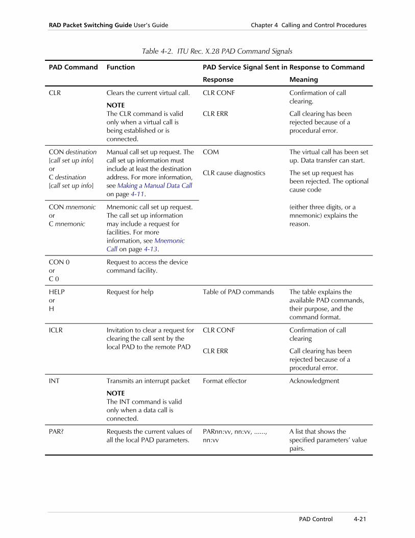
RAD Packet Switching Guide User’s Guide Chapter 4 Calling and Control Procedures
PAD Control 4-21
Table 4-2. ITU Rec. X.28 PAD Command Signals
PAD Command Function PAD Service Signal Sent in Response to Command
Response Meaning
CLR Clears the current virtual call.
NOTE The CLR command is valid only when a virtual call is being established or is connected.
CLR CONF
CLR ERR
Confirmation of call clearing.
Call clearing has been rejected because of a procedural error.
CON destination [call set up info] or C destination [call set up info]
Manual call set up request. The call set up information must include at least the destination address. For more information, see Making a Manual Data Call on page 4-11.
COM
CLR cause diagnostics
The virtual call has been set up. Data transfer can start.
The set up request has been rejected. The optional cause code
CON mnemonic or C mnemonic
Mnemonic call set up request. The call set up information may include a request for facilities. For more information, see Mnemonic Call on page 4-13.
(either three digits, or a mnemonic) explains the reason.
CON 0 or C 0
Request to access the device command facility.
HELP or H
Request for help Table of PAD commands The table explains the available PAD commands, their purpose, and the command format.
ICLR Invitation to clear a request for clearing the call sent by the local PAD to the remote PAD
CLR CONF
CLR ERR
Confirmation of call clearing
Call clearing has been rejected because of a procedural error.
INT Transmits an interrupt packet
NOTE The INT command is valid only when a data call is connected.
Format effector Acknowledgment
PAR? Requests the current values of all the local PAD parameters.
PARnn:vv, nn:vv, ......, nn:vv
A list that shows the specified parameters’ value pairs.

Chapter 4 Calling and Control Procedures RAD Packet Switching Guide User’s Guide
4-22 PAD Control
Table 4-2. ITU Rec. X.28 PAD Command Signals (Cont.)
PAD Command Function PAD Service Signal Sent in Response to Command
Response Meaning
PAR?nn, nn, ...., nn
Requests the current values of the specified local PAD parameters.
PARnn:vv, nn:vv, ......, nn:vv
PARnn:INV
A list that shows the specified parameters: value pairs.
The parameter number nn is invalid.
PROF profile-number
Assigns values to local PAD parameters by loading the specified profile. The range of profile numbers accepted by the device PAD is 1 through 256.
Format effector
NOT FOUND
Acknowledgment
The requested profile has not been found.
RESET Sends a reset packet. All incoming or outgoing data in transit is deleted.
NOTE The RESET command is valid only when a data call is being connected or is being cleared. A connected call is not disconnected by this command.
Format effector Acknowledgment
RPAR? Request transmitted to the remote PAD, to send the current values of all remote PAD parameters.
PARnn:vv, nn:vv, ...., nn:vv A list that shows the specified parameters’ value pairs.
RPAR?nn, nn, ...., nn
Request transmitted to the remote PAD, to send the specified remote PAD parameters.
PARnn:vv, nn:vv, ...., nn:vv
PARnn:INV
A list that shows the specified parameters’ value pairs.
The parameter number nn is invalid.
RSETnn:vv, nn:vv, ...., nn:vv
Request transmitted to the remote PAD, to change the current values of the specified remote PAD parameters.
Format effector Acknowledgment that the specified parameters have been assigned new values.
RSET?nn:vv, nn:vv, ...., nn:vv
Request transmitted to the remote PAD to change the current values of the remote PAD specified parameters, and to display the changed values of the specified parameters.
PARnn:vv, nn:vv, ...., nn:vv
PARnn:INV
A list that shows the specified parameters: value pairs.
The parameter number nn is invalid.
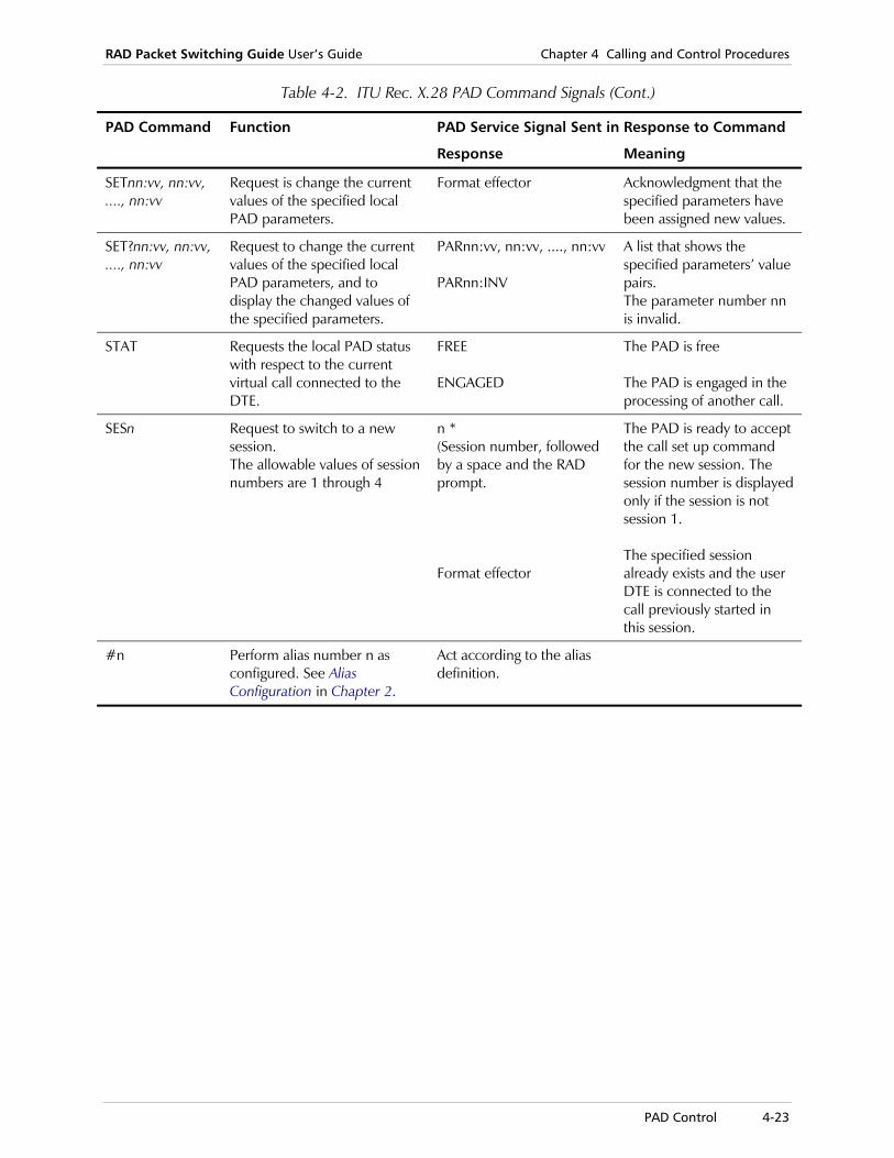
RAD Packet Switching Guide User’s Guide Chapter 4 Calling and Control Procedures
PAD Control 4-23
Table 4-2. ITU Rec. X.28 PAD Command Signals (Cont.)
PAD Command Function PAD Service Signal Sent in Response to Command
Response Meaning
SETnn:vv, nn:vv, ...., nn:vv
Request is change the current values of the specified local PAD parameters.
Format effector Acknowledgment that the specified parameters have been assigned new values.
SET?nn:vv, nn:vv, ...., nn:vv
Request to change the current values of the specified local PAD parameters, and to display the changed values of the specified parameters.
PARnn:vv, nn:vv, ...., nn:vv PARnn:INV
A list that shows the specified parameters’ value pairs. The parameter number nn is invalid.
STAT Requests the local PAD status with respect to the current virtual call connected to the DTE.
FREE ENGAGED
The PAD is free The PAD is engaged in the processing of another call.
SESn Request to switch to a new session. The allowable values of session numbers are 1 through 4
n * (Session number, followed by a space and the RAD prompt. Format effector
The PAD is ready to accept the call set up command for the new session. The session number is displayed only if the session is not session 1. The specified session already exists and the user DTE is connected to the call previously started in this session.
#n Perform alias number n as configured. See Alias Configuration in Chapter 2.
Act according to the alias definition.
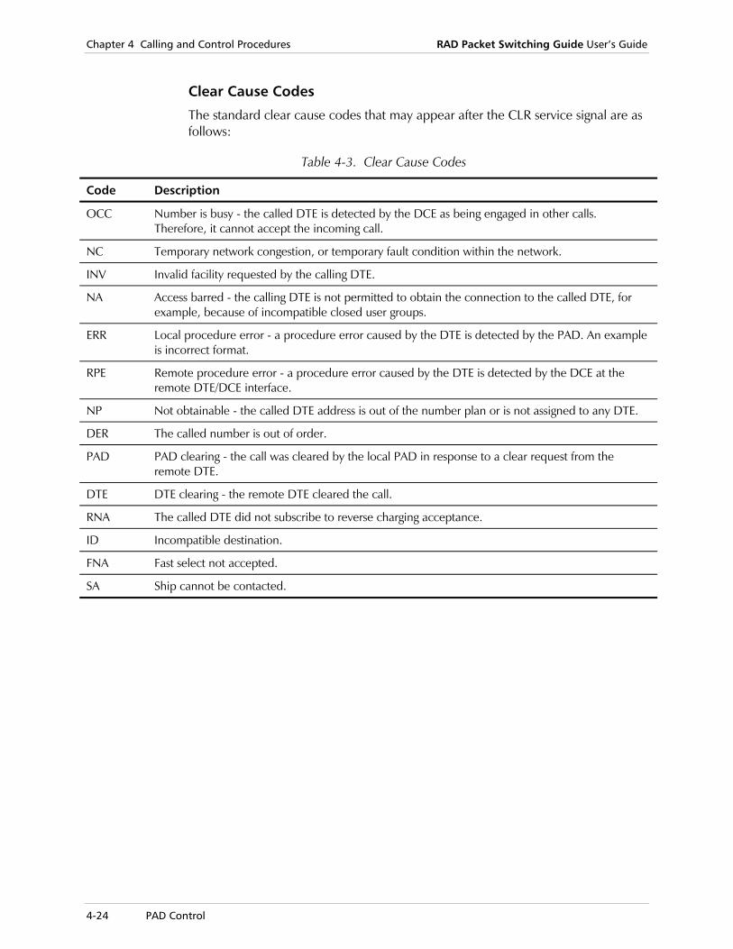
Chapter 4 Calling and Control Procedures RAD Packet Switching Guide User’s Guide
4-24 PAD Control
Clear Cause Codes
The standard clear cause codes that may appear after the CLR service signal are as follows:
Table 4-3. Clear Cause Codes
Code Description
OCC Number is busy - the called DTE is detected by the DCE as being engaged in other calls. Therefore, it cannot accept the incoming call.
NC Temporary network congestion, or temporary fault condition within the network.
INV Invalid facility requested by the calling DTE.
NA Access barred - the calling DTE is not permitted to obtain the connection to the called DTE, for example, because of incompatible closed user groups.
ERR Local procedure error - a procedure error caused by the DTE is detected by the PAD. An example is incorrect format.
RPE Remote procedure error - a procedure error caused by the DTE is detected by the DCE at the remote DTE/DCE interface.
NP Not obtainable - the called DTE address is out of the number plan or is not assigned to any DTE.
DER The called number is out of order.
PAD PAD clearing - the call was cleared by the local PAD in response to a clear request from the remote DTE.
DTE DTE clearing - the remote DTE cleared the call.
RNA The called DTE did not subscribe to reverse charging acceptance.
ID Incompatible destination.
FNA Fast select not accepted.
SA Ship cannot be contacted.

RAD Packet Switching Guide User’s Guide Chapter 4 Calling and Control Procedures
PAD Control 4-25
Table 4-4. PAD Service Signals
Code Description
BS SP BS Indication of “character delete function completed” (used only for video terminals).
CLR [cause] [diagnostics] Indication of clearing, and the equipment that initiated the action (optional).
CLR CONF Confirmation of clearing request.
COM Indication of call connected, or call received from the network.
ERR Indication that a PAD command is in error.
ENGAGED Response to the STAT command (status request) when a call is established on the current session.
Format Effector PAD acknowledgment; causes screen cursor to move to the beginning of the next display line.
FREE Response to the STAT command (status request) when no call is established on the current session.
PAGE Indication that a page wait condition occurred.
PARnn:INV Response to set and read PAD command if at least one parameter is invalid.
RESET [cause] [diagnostics] Indication from the X.25 network that the virtual call was reset; optionally, includes a cause code and a diagnostic code.
RESET NOT FOUND Profile not found in profile command.
RESET INACTIVITY TIME OUT Call cleared because of inactivity time-out.
XXX Indication of “line delete function completed” (used only for printing terminals).
* Default PAD prompt (other characters can be defined by the user).
\ Indication of “character delete function completed” (used only for printing terminals).
The diagnostic codes that may appear after the RESET service signal are specified in ITU Rec. X.25. Some networks may not provide these codes.
Note

Chapter 4 Calling and Control Procedures RAD Packet Switching Guide User’s Guide
4-26 Telnet Control
Table 4-5. Reset Cause Codes
Code Description
DTE The call was reset by the remote device. Data may be lost.
DER PVC out of order.
RPE The call was reset by network, remote procedure error, data may be lost.
ERR The call was reset by network, local procedure error, data may be lost.
NC The call was reset due to temporary network problem, data may be lost.
DTO PVC, remote DTE operational.
NO PVC, network operational.
ICD Incompatible destination.
NER Network out of order.
4.4 Telnet Control
The RAD Packet Switching devices support Telnet control commands. The following table lists the Telnet commands supported. For more information, see Chapter 7 - Protocols.
Table 4-6. Telnet Control Commands
Command Function
Telnet X.X.X.X Open a new Telnet session, where X.X.X.X is the IP address of the remote server. This command is activated from the X.28 prompt.
Open X.X.X.X Open a new Telnet session where X.X.X.X is the IP address of the remote server. This command is similar to the Telnet command but activated from the Telnet prompt (Telnet>).
close Close the current Telnet session.
CONTROL + P Display the Telnet prompt (Telnet>).
Send IP Interupt Process, send interupt to stop the process. Activated from the Telnet prompt.
Send ayt “Are you there” inquiry checks if there is communication between the terminal and the destination. Activated from the Telnet prompt.
Send ao “Abort output” command prevents the terminal from receiving output from the application running on the destination. Activated from the Telnet prompt.
quit Close the current Telnet session and exit from the Telnet environment. Activated from the Telnet prompt.

Displaying System Status 5-1
Chapter 5 Status and Statistics This chapter explains the statistic and status information collected by the device, and provides operating instructions.
The statistics and status information is hierarchically organized, as shown on page 5-2. Therefore, you can select the amount of detail to be displayed, according to your requirements:
• The top-level screen, displayed if Statistics is selected on the main menu, presents a concise display of the system status.
• Separate statistics and status screens for the asynchronous channels and the synchronous links can be displayed.
• Protocol cuts screens, according to the different protocols, display statistics information in a more concentrated format.
• Detailed information at the level of individual channels can be displayed. In addition to statistics data, the individual channel screens present important information that can be used by technical support personnel to analyze and troubleshoot system problems.

Chapter 5 Status and Statistics RAD Packet Switching Guide User’s Guide
5-2 Displaying System Status
SYSTEM STATISTICS MAINSCREEN
A Async channels1-3 Sync linksP Protocols
INDIVIDUALSTATUS SCREEN
INDIVIDUALLINK STATISTICS
SCREEN
ASYNCHRONOUSCHANNEL STATUS
SCREEN
PROTOCOLSFrame Relay
SNAIP
IPPROTOCOLS
SCREEN
FRAME RELAYPROTOCOLS
SCREEN
SNAPROTOCOLS
SCREEN
Figure 5-1. Device Status and Statistics Functions

RAD Packet Switching Guide User’s Guide Chapter 5 Status and Statistics
Displaying System Status 5-3
5.1 Displaying System Status
The System Status screen displays system status information, and provides access to statistics for the device’s individual links.
To display the System Status screen
1. In the Main menu, select 4 (Status and Statistics) and press <Enter>. The System Status screen appears, showing the system status at the time you pressed <Enter>. This is called a system snapshot.
TIME: 09:48:56 DATE: Jul-07-1998 START: 08:41:26 DATE: Jul-07-1998
SYSTEM STATUS
--------------------------------------
Device ID: 0
Device MAC ADDRESS: 1234 1234 1234 Running Version: ADVANCE
RAM Size: 7680 KByte Free DATA buffers: 11096
NOVRAM Size: 32 KByte MIN DATA buffers in pool: 11065
NOVRAM Utilization: 4 %
Par\Lnk| 1 | 2 | 3 | 4 | 5 | 6 | 7 | 8 |
-------|-----|-----|-----|-----|-----|-----|-----|-----|
PROTOC |X.25 |X.25 |X.25 |X.25 |X.25 |X.25 |X.25 |X.25 |
Sync | NO | NO | NO | NO | NO | NO | NO | NO |
S loss | 0 | 0 | 0 | 0 | 0 | 0 | 0 | 0 |
I Pkts | 0 | 0 | 0 | 0 | 0 | 0 | 0 | 0 |
--------------------------------------------------------
MAIN STATUS and STATISTIC MENU
1 - 8) Sync Links A) Async Channels P) Protocols R) Refresh <CR>) Exit
Select option:
Figure 5-2. Sample System Status Screen

Chapter 5 Status and Statistics RAD Packet Switching Guide User’s Guide
5-4 Displaying System Status
2. If you want, do any of the following: To take a new system snapshot, type R and press <Enter>.
To open the Asynchronous Channels Statistics screen (see Asynchronous X.28 Channels Status Screen on page 5-7), type A and press <Enter>.
To open the individual Synchronous Link Statistics screen, type the link number you want and press <Enter>.
To open the Protocol Cut screen, type P and press <Enter>.
3. To return to the Main menu, press <Enter> without selecting an option.
System Status Screen The System Status screen snapshot displays information about the following parameters:
Time and Date Information
The screen shows the current time and date, and the starting time and date for the collection of the statistical data displayed by the device.
The starting time is the later of the following events:
• The time the device has been turned on (or reset).
• The time the statistics counters were reset, using the SystemControl menu.
Device ID The identification of the device (defined through the System Parameters Screen).
Device MAC Address
MAC Address of the device.
RAM Size The size of the RAM installed in the device (256 - [??] Kb, in accordance with your order).
NOVRAM Size The size of the NOVRAM installed in the device (2 - 32 Kb, in accordance with your order).
NOVRAM Utilization
The percentage of installed NOVRAM capacity that is used to store user prepared information.
If NOVRAM utilization is high, use the Rearrange NOVRAM function to rearrange the stored information, and recover gaps in the storage area.
Note

RAD Packet Switching Guide User’s Guide Chapter 5 Status and Statistics
Displaying System Status 5-5
Running Version Version of the software running in the device, in accordance to the Enable Software Upgrade function (see Enable Software Upgrade in Chapter 3).
FREE DATA Buffers
Number of available data buffers in the pool.
MIN DATA Buffers in Pool
The recorded minimum number of data buffers in the pool since the last time the device was turned on, reset or had its statistics reset.
Protoc The current protocol type of the links, for each link.
Sync The current synchronization status for each link:
X.25 links The link is synchronized - YES or NO.
FR links Port is UP or DOWN.
HDLC links PVC.
S loss The number of synchronization losses for each X.25 link.
I Pkts Total number of information packets transmitted and received by layer 3 (the X.25 layer), for each link. Only the 5 LSB digits are shown. To view the whole I packet number, open the specific Individual Link Status screen.
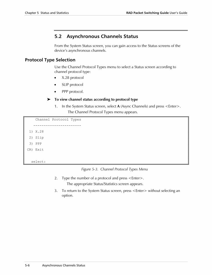
Chapter 5 Status and Statistics RAD Packet Switching Guide User’s Guide
5-6 Asynchronous Channels Status
5.2 Asynchronous Channels Status
From the System Status screen, you can gain access to the Status screens of the device’s asynchronous channels.
Protocol Type Selection Use the Channel Protocol Types menu to select a Status screen according to channel protocol type:
• X.28 protocol
• SLIP protocol
• PPP protocol.
To view channel status according to protocol type
1. In the System Status screen, select A (Async Channels) and press <Enter>. The Channel Protocol Types menu appears.
Channel Protocol Types
-----------------------
1) X.28
2) Slip
3) PPP
CR) Exit
select:
Figure 5-3. Channel Protocol Types Menu
2. Type the number of a protocol and press <Enter>. The appropriate Status/Statistics screen appears.
3. To return to the System Status screen, press <Enter> without selecting an option.
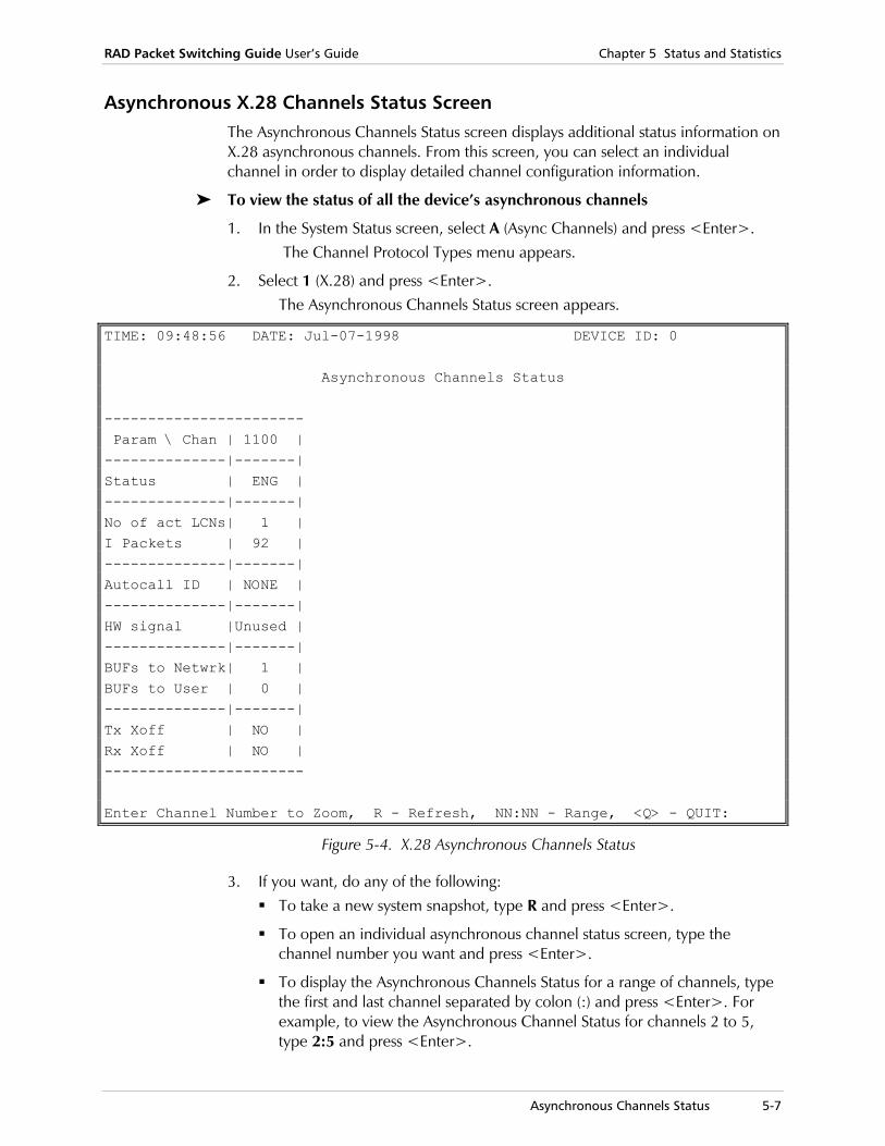
RAD Packet Switching Guide User’s Guide Chapter 5 Status and Statistics
Asynchronous Channels Status 5-7
Asynchronous X.28 Channels Status Screen The Asynchronous Channels Status screen displays additional status information on X.28 asynchronous channels. From this screen, you can select an individual channel in order to display detailed channel configuration information.
To view the status of all the device’s asynchronous channels
1. In the System Status screen, select A (Async Channels) and press <Enter>. The Channel Protocol Types menu appears.
2. Select 1 (X.28) and press <Enter>. The Asynchronous Channels Status screen appears.
TIME: 09:48:56 DATE: Jul-07-1998 DEVICE ID: 0
Asynchronous Channels Status ----------------------- Param \ Chan | 1100 | --------------|-------| Status | ENG | --------------|-------| No of act LCNs| 1 | I Packets | 92 | --------------|-------| Autocall ID | NONE | --------------|-------| HW signal |Unused | --------------|-------| BUFs to Netwrk| 1 | BUFs to User | 0 | --------------|-------| Tx Xoff | NO | Rx Xoff | NO | ----------------------- Enter Channel Number to Zoom, R - Refresh, NN:NN - Range, <Q> - QUIT:
Figure 5-4. X.28 Asynchronous Channels Status
3. If you want, do any of the following: To take a new system snapshot, type R and press <Enter>.
To open an individual asynchronous channel status screen, type the channel number you want and press <Enter>.
To display the Asynchronous Channels Status for a range of channels, type the first and last channel separated by colon (:) and press <Enter>. For example, to view the Asynchronous Channel Status for channels 2 to 5, type 2:5 and press <Enter>.
Chapter 5 Status and Statistics RAD Packet Switching Guide User’s Guide
5-8 Asynchronous Channels Status
4. To return to the System Status screen, press <Enter> without selecting an option.
Asynchronous Channel Status Parameters
The Asynchronous Channel Status screen displays the following information:
Time and Date Information
The screen shows the current time and date.
Device ID The identification of the device (defined through the System Parameters Screen).
Status Displays information on the logical channel currently used by each asynchronous channel.
FREE The asynchronous channel is free.
ENG The asynchronous channel is engaged in a call.
No. of Act. LCNs Number of active logical channels used by each asynchronous channel.
I Packets Total number of information packets transmitted and received by layer 3 (the X.25 layer), for each X.28 link.
AutoCall ID Indicates if each asynchronous channel was configured to use the autocall function, and what the Call ID is. NONE indicates that the channel is not configured for autocall.
HW Signal Shows the state of the HW signal of each asynchronous channel.
OFF HW signal is not active (the user’s DTE does not request permission to transmit).
ON HW signal is active (the user’s DTE wants to transmit data).
UNUSED The channel PAD ignores the state of the HW signal.
BUFs to Netwrk Number of data buffers currently used by the transmit direction of each channel. The maximum number of buffers is 16. When the maximum is reached, the data is discarded. See also Tx Xoff below.
BUFs to User Number of data buffers currently used by the receive direction of each channel. The maximum number of buffers is 16. When the maximum is reached, the data is being discarded. See also Rx Xoff below.
RAD Packet Switching Guide User’s Guide Chapter 5 Status and Statistics
Asynchronous Channels Status 5-9
Tx Xoff Indicates the current state of software flow control in the transmit direction:
NO Traffic flow enabled.
YES Traffic flow from the user’s DTE to the channel was interrupted by sending the X-OFF character to the DTE.
For example, if X.25 synchronization is lost, the DTE stops sending data to the X.25 network.
If the DTE continues to send data, the buffers to network allocated to this channel eventually fill. When this occurs, the Asynchronous Channels Status screen shows 9 in the BUFs To Netwrk field of the corresponding channel.
In this case, the X-OFF character is then sent to the DTE, and the screen shows YES in the Tx Xoff field.
Rx Xoff Indicates the current state of software flow control in the receivedirection:
NO Traffic flow enabled.
YES Traffic flow from the channel to the user’s DTE stopped when the DTE sent the X-OFF character to the device.
For example, if the DTE cannot accept data, it will send an X-OFF character to the device. In this case, the screen shows YES in the Rx Xoff field.
The channel PAD then stops the transfer of data received from the X.25 network to this DTE and stores it in the buffers to user allocated to this channel. When this occurs, the Asynchronous Channels Status screen shows 9 in the BUFs To User field of the corresponding channel.
If these buffers fill, the device will send an RNR packet to signal the remote device to stop the transmission of data.
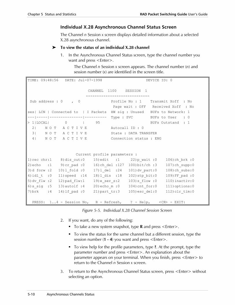
Chapter 5 Status and Statistics RAD Packet Switching Guide User’s Guide
5-10 Asynchronous Channels Status
Individual X.28 Asynchronous Channel Status Screen
The Channel n Session x screen displays detailed information about a selected X.28 asynchronous channel.
To view the status of an individual X.28 channel
1. In the Asynchronous Channel Status screen, type the channel number you want and press <Enter>.
The Channel n Session x screen appears. The channel number (n) and session number (x) are identified in the screen title.
TIME: 09:48:56 DATE: Jul-07-1998 DEVICE ID: 0
CHANNEL 1100 SESSION 1
-----------------------------
Sub address : 0 , 0 Profile No : 1 Transmit Xoff : No
Page wait : OFF Received Xoff : No
ses| LCN | Connected to | I Packets HW sig : Unused BUFs to Network: 1
---|-----|---------------|---------- Type : SVC BUFs to User : 0
> 1|LOCAL| 0 | 95 BUFs Outstand : 1
2| N O T A C T I V E Autocall ID : 0
3| N O T A C T I V E State : DATA TRANSFER
4| N O T A C T I V E Connection status : ENG
Current profile parameters :
1)rec chr:1 8)dis_out:0 15)edit :1 22)p_wait :0 106)ch_brk :0
2)echo :1 9)cr_pad :0 16)ch_del :127 100)bit/ch :3 107)ch_supp:0
3)d forw :2 10)l_fold :0 17)l_del :24 101)dv_part:0 108)ch_subs:0
4)idl_t :0 11)speed :14 18)l_dis :18 102)stp_bit:0 109)FF_pad :0
5)dv_flw :2 12)pad_flw:1 19)e_ser_s:2 103)s_flow :0 110)inactiv:0
6)s_sig :5 13)autolf :4 20)echo_m :0 104)cnt_for:0 111)options:0
7)brk :4 14)lf_pad :0 21)part_tr:3 105)esc_del:0 112)clr_tim:0
PRESS: 1..4 - Session No, R - Refresh, ? - Help, <CR> - EXIT:
Figure 5-5. Individual X.28 Channel Session Screen
2. If you want, do any of the following: To take a new system snapshot, type R and press <Enter>.
To view the status for the same channel but a different session, type the session number (1 - 4) you want and press <Enter>.
To view help for the profile parameters, type ?. At the prompt, type the parameter number and press <Enter>. An explanation about the parameter appears on your terminal. When you finish, press <Enter> to return to the Channel n Session x screen.
3. To return to the Asynchronous Channel Status screen, press <Enter> without selecting an option.

RAD Packet Switching Guide User’s Guide Chapter 5 Status and Statistics
Asynchronous Channels Status 5-11
X.28 Channel Status Parameters
The Channel n Session x screen displays the following information:
Time and Date Information
The screen shows the current time and date.
Device ID The identification of the device (defined through the System Parameters Screen).
Subaddress The subaddresses assigned to the selected channel. Each channel can be assigned two subaddresses. A comma separates the first and second subaddresses.
0 in a subaddress field indicates that no subaddress was assigned.
Profile No. The number of the profile currently used by the selected channel.
Page Wait Indicates whether the data traffic through the channel has been interrupted due to a page wait condition:
ON Page wait request was received.
OFF Normal state.
HW Sig Shows the state of the HW signal of each asynchronous channel.
OFF HW signal is not active (the user’s DTE does not request permission to transmit).
ON HW signal is active (the user’s DTE wants to transmit data).
UNUSED The channel PAD ignores the state of the HWsignal.
Type Channel type:
SVC Switched virtual circuit.
PVC Permanent virtual circuit.
AutoCall ID Indicates if the selected channel was configured to use the autocall function, and what the Call ID is. NONE indicates that the channel is not configured for autocall.
State Current channel mode:
DATA TRANSFER Channel is in the data transfer mode.
X.28 COMMAND Channel is in the command mode.
Chapter 5 Status and Statistics RAD Packet Switching Guide User’s Guide
5-12 Asynchronous Channels Status
Connection Status
Current state of the selected channel:
FREE The channel is free.
ENG The channel is engaged in a call.
Transmit Xoff Indicates the current state of software flow control in the transmit direction:
NO Traffic flow enabled.
YES Traffic flow from the user’s DTE to the channel was interrupted by sending the X-OFF character to the DTE.
For example, if X.25 synchronization is lost, the DTE stops sending data to the X.25 network.
If the DTE continues to send data, the buffers to network allocated to this channel eventually fill. When this occurs, the Asynchronous Channels Status screen shows 9 in the BUFs To Netwrk field of the corresponding channel.
In this case, the X-OFF character is then sent to the DTE, and the screen shows YES in the Tx Xoff field.
Received Xoff Indicates the current state of software flow control in the receivedirection:
NO Traffic flow enabled.
YES Traffic flow from the channel to the user’s DTE was interrupted when the DTE sent the X-OFF character to the device.
For example, if the DTE cannot accept data, it will send an X-OFF character to the device. In this case, the screen shows YES in the Rx Xoff field.
The channel PAD then stops the transfer of data received from the X.25 network to this DTE and stores it in the buffers to user allocated to this channel. When this occurs, the Asynchronous Channels Status screen shows 9 in the BUFs To User field of the corresponding channel.
If these buffers fill, the device will send an RNR packet in order to signal the remote device to stop the transmission of data.
BUFs to Network Number of data buffers currently used by the transmit direction of each channel. The maximum number of buffers is 16. When the maximum is reached, the data is discarded. See also Tx Xoff below.
BUFs to User Number of data buffers currently used by the receive direction of each channel. The maximum number of buffers is 16. When the maximum is reached, the data is being discarded. See also Rx Xoff below.

RAD Packet Switching Guide User’s Guide Chapter 5 Status and Statistics
Asynchronous Channels Status 5-13
BUFs Outstand An internal software variable.
Ses An index showing the session number. Each line shows status information for that session. An arrow indicates the current active session.
LCN Indicates the numbers of the logical channels used by the selected channels.
The table includes one line for each session. See Table 5-1 for the available values.
Connected to The X.25 address of the remote subscriber to which the selectedchannel is now connected through the logical channel appearing in the same line.
The table includes one line for each session. See Table 5-1 for the available values.
I Packets Total number of information packets transmitted up to the time shown in the screen header through this logical channel.
The table includes one line for each session. See Table 5-1 for the available values.
Current Profile Parameters
List of PAD parameter values included in the profile being used by the selected channel. Note that these values reflect changes made by you or by the remote PAD or switched during the ongoing call. Concise help is available for each of the parameters.
For more information about these parameters, see PAD Parameters in Chapter 2.
Table 5-1 lists the different session types, and the available values for the session table parameters in Figure 5-5.
Table 5-1. Session Types and Matching Parameter Values
Session Type LCN Connected to I Packet Remarks
External Call # X.25 Address of the Subcarrier
Number of Packets
# is the logical channel number
Local Call LOCAL The physical channel number
Configuration LOCAL 0 0 is the connection number for the command facility
Free (not engaged)
Free
PVC # PVC Number of packets
# is the logical channel number
Not Active N O T A C T I V E The words “NOT ACTIVE” appear across the line. There is no separate column line

Chapter 5 Status and Statistics RAD Packet Switching Guide User’s Guide
5-14 Asynchronous Channels Status
SLIP Channel Statistics Screen
The SLIP Channel Statistics screen displays statistical information on SLIP channels. From this screen, you can select an individual channel in order to display detailed channel configuration information.
To view the statistics of all the device’s SLIP channels
1. In the System Status screen, select A (Async Channels) and press <Enter>. The Channel Protocol Types menu appears.
2. Select 2 (Slip) and press <Enter>. The SLIP Channel Statistics screen appears.
DEVICE ID: 0 START: 12:59:12 TIME: 12:59:27
SLIP CHANNEL Statistics
Channel no. | 400 |
------------|----------|
R frame pool| 59 |
Buffers | 0 |
Datagrams Rx| 0 |
Datagrams Tx| 0 |
Errors Rx| 0 |
Errors Tx| 0 |
CTS state | ON |
PRESS: R-Refresh, NN:NN-For range display, Q-Quit, <CR>-Continue:
Figure 5-6. SLIP Channel Statistics Screen
3. If you want, do any of the following: Press <Enter> to continue to another screen.
To take a new system snapshot, type R and press <Enter>.
To display the SLIP Channels Statistics for a range of channels, type the first and last channel separated by colon (:) and press <Enter>. For example, to view the SLIP Channel Status for channels 2 to 5, type 200:500 and press <Enter>.
4. To return to the System Status screen, type Q and press <Enter>.

RAD Packet Switching Guide User’s Guide Chapter 5 Status and Statistics
Asynchronous Channels Status 5-15
SLIP Channel Statistics Parameters
The SLIP Channel Status screen displays the following information:
Device ID The identification of the device (defined through the System Parameters Screen).
Start Time and Current Time
The screen shows the current time and date, and the starting time and date for the collection of the statistical data displayed by the device.
The starting time is the later of the following events:
• The time the device has been turned on (or reset).
• The time the statistics counters were reset, using the System Control menu.
R Frame Pool Number of free buffers that can receive data. If the value is below -2, link status is defined as busy.
Buffers Number of buffers in the channel awaiting completion of packet assembly at the moment that the statistics were displayed or refreshed.
Datagrams Rx The number of datagrams received by the channel.
Datagrams Tx The number of datagrams transmitted by the channel.
Errors Rx The total number of detected errors on received data, for the channel since the device was turned on or reset.
Errors Tx The total number of detected errors on transmitted data, for the channel since the device was turned on or reset.
CTS State Indicates the state of the link CTS signal.
ON CTS signal is active (normal traffic condition).
OFF CTS signal is off.

Chapter 5 Status and Statistics RAD Packet Switching Guide User’s Guide
5-16 Asynchronous Channels Status
PPP Channel Statistics Screen
The PPP Channel Statistics screen displays statistical information on PPP channels. From this screen, you can select an individual channel in order to display detailed channel configuration information.
To view the statistics of all the device’s PPP channels
1. In the System Status screen, select A (Async Channels) and press <Enter>. The Channel Protocol Types menu appears.
2. Select 3 (PPP) and press <Enter>. The PPP Statistics screen appears.
DEVICE ID: 0 START: 12:59:12 TIME: 13:03:54
PPP Statistics
Link no. | 1 |
------------|----------|
R frame pool| 59 |
Buffers | 0 |
Datagrams Rx| 0 |
Datagrams Tx| 188 |
Errors Rx| 0 |
Errors Tx| 0 |
CTS state | ON |
PRESS: R - Refresh, <CR> - EXIT:
Figure 5-7. PPP Channel Statistics Screen
3. If you want to take a new system snapshot, type R and press <Enter>.
4. To return to the System Status screen, press <Enter>.
RAD Packet Switching Guide User’s Guide Chapter 5 Status and Statistics
Asynchronous Channels Status 5-17
PPP Channel Statistics Parameters
The PPP Channel Status screen displays the following information:
Device ID The identification of the device (defined through the System Parameters Screen).
Start Time and Current Time
The screen shows the current time and date, and the starting time and date for the collection of the statistical data displayed by the device.
The starting time is the later of the following events:
• The time the device has been turned on (or reset).
• The time the statistics counters were reset, using the SystemControl menu.
R Frame Pool Number of free buffers that can receive data. If the value is below -2, link status is defined as busy.
Buffers Number of buffers in the channel awaiting completion of packetassembly at the moment that the statistics were displayed or refreshed.
Datagrams Rx The number of datagrams received by the channel.
Datagrams Tx The number of datagrams transmitted by the channel.
Errors Rx The total number of detected errors on received data, for the channel since the device was turned on or reset.
Errors Tx The total number of detected errors on transmitted data, for the channel since the device was turned on or reset.
CTS State Indicates the state of the link CTS signal.
ON CTS signal is active (normal traffic condition).
OFF CTS signal is off.
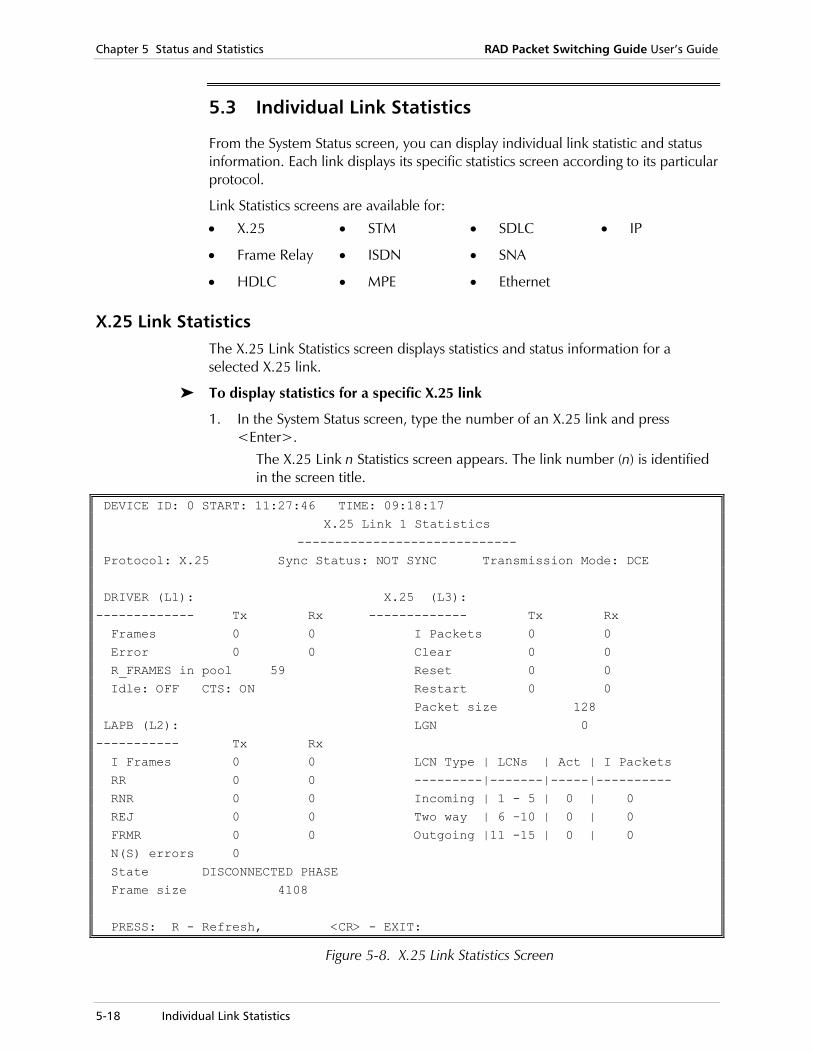
Chapter 5 Status and Statistics RAD Packet Switching Guide User’s Guide
5-18 Individual Link Statistics
5.3 Individual Link Statistics
From the System Status screen, you can display individual link statistic and status information. Each link displays its specific statistics screen according to its particular protocol.
Link Statistics screens are available for:
• X.25 • STM • SDLC • IP
• Frame Relay • ISDN • SNA
• HDLC • MPE • Ethernet
X.25 Link Statistics The X.25 Link Statistics screen displays statistics and status information for a selected X.25 link.
To display statistics for a specific X.25 link
1. In the System Status screen, type the number of an X.25 link and press <Enter>.
The X.25 Link n Statistics screen appears. The link number (n) is identified in the screen title.
DEVICE ID: 0 START: 11:27:46 TIME: 09:18:17
X.25 Link 1 Statistics
-----------------------------
Protocol: X.25 Sync Status: NOT SYNC Transmission Mode: DCE
DRIVER (L1): X.25 (L3):
------------- Tx Rx ------------- Tx Rx
Frames 0 0 I Packets 0 0
Error 0 0 Clear 0 0
R_FRAMES in pool 59 Reset 0 0
Idle: OFF CTS: ON Restart 0 0
Packet size 128
LAPB (L2): LGN 0
----------- Tx Rx
I Frames 0 0 LCN Type | LCNs | Act | I Packets
RR 0 0 ---------|-------|-----|----------
RNR 0 0 Incoming | 1 - 5 | 0 | 0
REJ 0 0 Two way | 6 -10 | 0 | 0
FRMR 0 0 Outgoing |11 -15 | 0 | 0
N(S) errors 0
State DISCONNECTED PHASE
Frame size 4108
PRESS: R - Refresh, <CR> - EXIT:
Figure 5-8. X.25 Link Statistics Screen
RAD Packet Switching Guide User’s Guide Chapter 5 Status and Statistics
Individual Link Statistics 5-19
2. If you want to take a new system snapshot, type R and press <Enter>.
3. To return to the System Status screen, press <Enter> without selecting an option.
X.25 Link Statistics Parameters
The X.25 Link n Statistics screen displays the following information:
Device ID The identification of the device (defined through the System Parameters Screen).
Start Time and Current Time
The screen shows the current time and date, and the starting time and date for the collection of the statistical data displayed by the device.
The starting time is the later of the following events:
• The time the device has been turned on (or reset).
• The time the statistics counters were reset, using the SystemControl menu.
Protocol Layer 3 protocol used by the link.
Sync Status X.25 synchronization status.
Possible values: SYNC or NOT SYNC.
Transmission Mode
X.25 and LAPB transmission mode.
Possible values: DTE or DCE.
Driver (L1) Summary of layer 1 statistics:
Frames Total number of frames transmitted and received by the link.
Error Total number of frames with errors transmitted and received by the link.
R_FRAMES in Pool Number of free buffers that can receive data. If the value is below 2, the link status is defined as busy.
IDLE State of the link: OFF - The link is active (normal traffic condition). ON - The link is idle (held continuously at MARK).
CTS State of the link’s CTS signal. ON - CTS signal is active (normal traffic condition). OFF - CTS signal is off.
Chapter 5 Status and Statistics RAD Packet Switching Guide User’s Guide
5-20 Individual Link Statistics
LAPB (L2) Summary of LAPB (layer 2) statistics:
I Frames Total number of Information (I) frames transmitted and received by the link.
RR Total number of Ready to Receive (RR) frames transmitted and received by the link.
RNR Total number of Not Ready to Receive (RNR) frames transmitted and received by the link.
REJ Total number of Reject (REJ) frames transmitted and received by the link.
FRMR Total number of Frame Reject (FRMR) frames transmitted and received by the link.
N(S) Errors Number of I frames transmitted out of sequence.
State Link state with respect to LAPB protocol: • DISCONNECTED PHASE • AWAITING ESTABLISH • AWAITING DISCONNECT • INFORMATION TRANSFER PHASE TIMER
RECOVERY • FRMR CONDITION.
Frame Size Size of layer 2 frames.
X.25 (L3) Summary of X.25 (layer 3) statistics:
I Packets Total number of Information packets transmitted and received by the link.
Clear Total number of clear packets transmitted and received by the link.
Reset Total number of reset packets transmitted and received by the link.
Restart Total number of restart packets transmitted and received by the link.
Packet size Current X.25 packet size.
LGN Logical group currently in use.
In addition, the X.25 data includes a table of logical channel utilization and state. For each type of logical channel (permanent, incoming-only, outgoing-only, and two-way), the table presents the following information:
LCNs Range of logical channels of each type.
Act Number of logical channels of each type that are now in use.
I Packets Total number of Information packets transmitted and received through each type of logical channels.
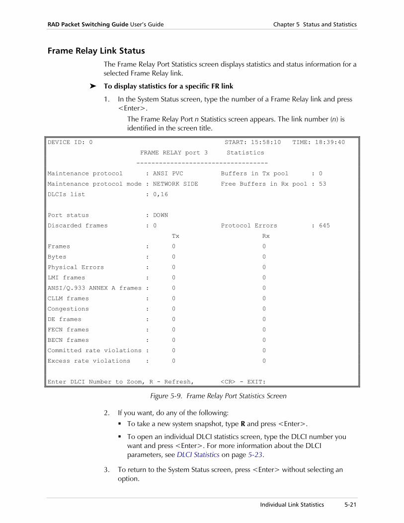
RAD Packet Switching Guide User’s Guide Chapter 5 Status and Statistics
Individual Link Statistics 5-21
Frame Relay Link Status The Frame Relay Port Statistics screen displays statistics and status information for a selected Frame Relay link.
To display statistics for a specific FR link
1. In the System Status screen, type the number of a Frame Relay link and press <Enter>.
The Frame Relay Port n Statistics screen appears. The link number (n) is identified in the screen title.
DEVICE ID: 0 START: 15:58:10 TIME: 18:39:40
FRAME RELAY port 3 Statistics
-----------------------------------
Maintenance protocol : ANSI PVC Buffers in Tx pool : 0
Maintenance protocol mode : NETWORK SIDE Free Buffers in Rx pool : 53
DLCIs list : 0,16
Port status : DOWN
Discarded frames : 0 Protocol Errors : 645
Tx Rx
Frames : 0 0
Bytes : 0 0
Physical Errors : 0 0
LMI frames : 0 0
ANSI/Q.933 ANNEX A frames : 0 0
CLLM frames : 0 0
Congestions : 0 0
DE frames : 0 0
FECN frames : 0 0
BECN frames : 0 0
Committed rate violations : 0 0
Excess rate violations : 0 0
Enter DLCI Number to Zoom, R - Refresh, <CR> - EXIT:
Figure 5-9. Frame Relay Port Statistics Screen
2. If you want, do any of the following: To take a new system snapshot, type R and press <Enter>.
To open an individual DLCI statistics screen, type the DLCI number you want and press <Enter>. For more information about the DLCI parameters, see DLCI Statistics on page 5-23.
3. To return to the System Status screen, press <Enter> without selecting an option.

Chapter 5 Status and Statistics RAD Packet Switching Guide User’s Guide
5-22 Individual Link Statistics
Frame Relay Link Statistics Parameters
The Frame Relay Port n Statistics screen displays the following information:
Device ID The identification of the device (defined through the System Parameters Screen).
Start Time and Current Time
The screen shows the current time and date, and the starting time and date for the collection of the statistical data displayed by the device.
The starting time is the later of the following events:
• The time the device has been turned on (or reset).
• The time the statistics counters were reset, using the SystemControl menu.
Maintenance Protocol
Frame Relay maintenance protocol for that port.
Possible values: NONE, ANSI PVC or LMI.
Maintenance Protocol Mode
Side that initiates the maintenance protocol.
Possible values: USER SIDE, NETWORK SIDE or USER AND NETWORK SIDE.
Buffers in TX Pool
Number of buffers awaiting transmission.
Free Buffers in RX Pool
Number of available buffers in the receive pool.
DLCIs List Existing DLCIs for the selected link.
Port Status Status of the selected link.
Possible values:
UP Management protocol is synchronized between the devices.
DOWN No management protocol exists or there is no synchronization between the devices.
Discarded Frames
Number of frames discarded by the port due to congestion.
Protocol Errors Number of protocol errors detected in the port.
Frames Total number of frames transmitted and received by the port.
Bytes Total number of bytes transmitted and received by the port.
LMI Frames Total number of Link Management Interface (LMI) protocol frames transmitted and received by the port.
ANSI/Q.933 ANNEX A Frames
Total number of American National Standards Institute (ANSI) protocol frames transmitted and received by the port.
CLLM Frames Total number of Consolidate Link Layer Management (CLLM) protocol frames transmitted and received by the port.

RAD Packet Switching Guide User’s Guide Chapter 5 Status and Statistics
Individual Link Statistics 5-23
Congestions Total number of congested frames transmitted and received by the port.
DE Frames Total number of frames with a Discard Eligibility (DE) bit set that were transmitted and received by the port.
FECN Frames Total number of frames with a Forward Explicit Congestion Notification (FECN) bit set that were transmitted and received by the port.
BECN Frames Total number of frames with a Backward Explicit Congestion Notification (BECN) bit set that were transmitted and received by the port.
Committed Rate Violations
Total number of committed rate violations that occur during data transmission and reception for that port.
Excess Rate Violations
Total number of excess rate violations that occur during data transmission and reception for that port.
DLCI Statistics
In the Frame Relay Port Statistics screen, type the DLCI number you want and press <Enter> to open an individual DLCI statistics screen.
DEVICE ID: 0 START: 15:58:10 TIME: 18:44:21
FRAME RELAY port 3 DLCI 16 Statistics
----------------------------------------------
Destination protocol : RFC 1490 Destination id : NOT USED
Funnel id : NONE
Funnel status : NONE
DLCI status : INACTIVE, NEW
Discarded frames : 0
Tx Rx
Frames : 0 0
Bytes : 0 0
DE frames : 0 0
FECN frames : 0 0
BECN frames : 0 0
Committed rate violations : 0 0
Excess rate violations : 0 0
R - Refresh, D - Destination Protocol Statistics, <CR> - EXIT:
Figure 5-10. Frame Relay Port n DLCI x Statistics Screen
Chapter 5 Status and Statistics RAD Packet Switching Guide User’s Guide
5-24 Individual Link Statistics
The Frame Relay Port n DLCI x Statistics screen displays the following information:
Device ID The identification of the device (defined through the System Parameters Screen).
Start Time and Current Time
The screen shows the current time and date, and the starting time and date for the collection of the statistical data displayed by the device.
The starting time is the later of the following events:
• The time the device has been turned on (or reset).
• The time the statistics counters were reset, using the SystemControl menu.
Destination Protocol
Protocol that is encapsulated over this DLCI (see DLCI Parameters in Chapter 2).
Destination ID Destination id for this DLCI.
Possible values:
NOT USED Destination ID is not used if the destination protocol is X.25 or HDLC.
Port:DLCI Port and DLCI numbers used for the destination ID if the destination protocol is Frame Relay.
Channel No. Asynchronous channel number used for the destination ID if the destination protocol is Async.
Funnel ID Funnel ID attached to this DLCI.
Funnel Status Status of the funnel that is attached to this DLCI.
Possible values:
NONE No funnel is attached to this DLCI.
NORMAL Normal operation of the funnel.
EXCEEDED Funnel is filling; data is being stored in funnel buffers.
OVERFLOW Data in funnel exceeded high water mark. Data may be discarded (see Funnel Parameters in Chapter 2).
DLCI Status DLCI status according to the maintenance messages that were received.
Possible values:
NEW DLCI was defined. No status messages for this DLCI were received.
ACTIVE DLCI is active. Data can be transferred on this DLCI.
INACTIVE DLCI is not active. Data cannot be transferred on this DLCI.
RAD Packet Switching Guide User’s Guide Chapter 5 Status and Statistics
Individual Link Statistics 5-25
Discarded Frames
Number of frames discarded and not transmitted by the DLCI.
Frames Total number of frames transmitted and received by the DLCI.
Bytes Total number of bytes transmitted and received by the DLCI.
DE Frames Total number of frames with a Discard Eligibility (DE) bit set that were transmitted and received by the DLCI.
FECN Frames Total number of frames with a Forward Explicit Congestion Notification (FECN) bit set that were transmitted and received by the DLCI.
BECN Frames Total number of frames with a Backward Explicit Congestion Notification (BECN) bit set that were transmitted and received by the DLCI.
Committed Rate Violations
Total number of committed rate violations that occur during data transmission and reception for that DLCI.
Excess Rate Violations
Total number of excess rate violations that occur during data transmission and reception for that DLCI.
Destination Protocol Statistics
The Destination Protocol Statistics screen displays statistics for the selected link according to the encapsulated protocol.
Opening the Destination Protocol Statistics screen is only possible for DLCIs that are encapsulated by another protocol. For example, if a DLCI’s Destination Protocol is X.25 encapsulation over the Frame Relay, typing D and pressing <Enter> for this DLCI displays the X.25 Link Statistics screen.
To display Destination Protocol Statistics
• In the Frame Relay Port n DLCI x Statistics screen, type D and press <Enter>.
The Destination Protocol Statistics screen appears.

Chapter 5 Status and Statistics RAD Packet Switching Guide User’s Guide
5-26 Individual Link Statistics
HDLC Link Status The HDLC Link Statistics screen displays statistics and status information for a selected HDLC link.
To display statistics for a specific HDLC link
1. In the System Status screen, type the number of an HDLC link and press <Enter>.
The HDLC Link n Statistics screen appears. The link number (n) is identified in the screen title.
DEVICE ID: 0 START: 11:27:46 TIME: 09:18:17
HDLC Link 3 Statistics
-----------------------------
Protocol: HDLC Status: DISC Encapsulation: X.25
DRIVER (L1): NETWORK:
------------- Tx Rx -------------
Frames 0 0 X.25 LCN NO CON
Error 0 0 DLCI NOT ACTIVE
R_FRAMES in pool 33
Idle: OFF CTS: OFF
FLOW CONTROL:
---------------
Frames Discarded 0
Max Buffers to Network 10
Buffers to Network 0
Clock Baud Rate NOT ACTIVE
PRESS: R - Refresh, <CR> - EXIT:
Figure 5-11. HDLC Link Statistics Screen
2. If you want to take a new system snapshot, type R and press <Enter>.
3. To return to the System Status screen, press <Enter> without selecting an option.

RAD Packet Switching Guide User’s Guide Chapter 5 Status and Statistics
Individual Link Statistics 5-27
HDLC Link Statistics Parameters
The HDLC Link n Statistics screen displays the following information:
Device ID The identification of the device (defined through the System Parameters Screen).
Start Time and Current Time
The screen shows the current time and date, and the starting time and date for the collection of the statistical data displayed by the device.
The starting time is the later of the following events:
• The time the device has been turned on (or reset).
• The time the statistics counters were reset, using the SystemControl menu.
Protocol Layer 3 protocol used by the link.
Status Communication status on the selected HDLC link.
Possible values:
DISC Link is disconnected.
BUSY Link is busy.
CON Link is connected (if link is defined X.25 SVC.
OVR Overflow - flow control activated.
PVC Link is PVC (if link is defined X.25 PVC, Frame Relay, or inner link.
Encapsulation Protocol over which the HDLC protocol is encapsulated.
Driver (L1) Summary of layer 1 statistics:
Frames Total number of frames transmitted and received by the link.
Error Total number of frames with errors transmitted and received by the link.
R_FRAMES in Pool Number of free buffers that can receive data. If the value is below 2, the link status is defined as busy.
IDLE State of the link: OFF - The link is active (normal traffic condition). ON - The link is idle (held continuously at MARK).
CTS State of the link’s CTS signal. ON - CTS signal is active (normal traffic condition). OFF - CTS signal is off.
Chapter 5 Status and Statistics RAD Packet Switching Guide User’s Guide
5-28 Individual Link Statistics
Network HDLC link to network encapsulation
X.25 LCN If the link is active, this is the value of LCN engaged in communication. NOT ACTIVE - HDLC not encapsulated over X.25. NO CON - No connection.
DLCI If the link is encapsulated over Frame Relay, this is the local port and DLCI used for encapsulation.
NOT ACTIVE - HDLC not encapsulated over FR.
Flow Control Summary of flow control statistics for this HDLC link:
Frames Discarded Total number of frames discarded and not transmitted by this link.
Max Buffers to Network Number of buffers available for the HDLC link. When these are full, the additional frames will be discarded.
Buffers to Network Number of data buffers currently used by the transmit direction of each link. The maximum number of buffers is 16. When the maximum is reached, the data is discarded.
Clock Baud Rate Shows baud rate of internal clock. NOT ACTIVE - Device uses external clock. Other value- baud rate of the internal clock.
STM Link Status For STM links, the asynchronous channels of the STM are displayed as in the Asynchronous Channels Status screen. No other link parameters are displayed. For more information, see Asynchronous Channel Status Parameters on page 5-7.
To display statistics for a specific STM link
1. In the System Status screen, type the number of an STM link and press <Enter>. The Asynchronous Channels Status screen appears.
2. If you want, do any of the following: To take a new system snapshot, type R and press <Enter>.
To open an individual STM asynchronous channel status screen, type the channel number you want and press <Enter>.
To display the Asynchronous Channels Status for a range of STM channels, type the first and last channel separated by colon (:) and press <Enter>. For example, to view the Asynchronous Channel Status for STM channels 2 to 5, type 2:5 and press <Enter>.
3. To return to the System Status screen, press <Enter> without selecting an option.
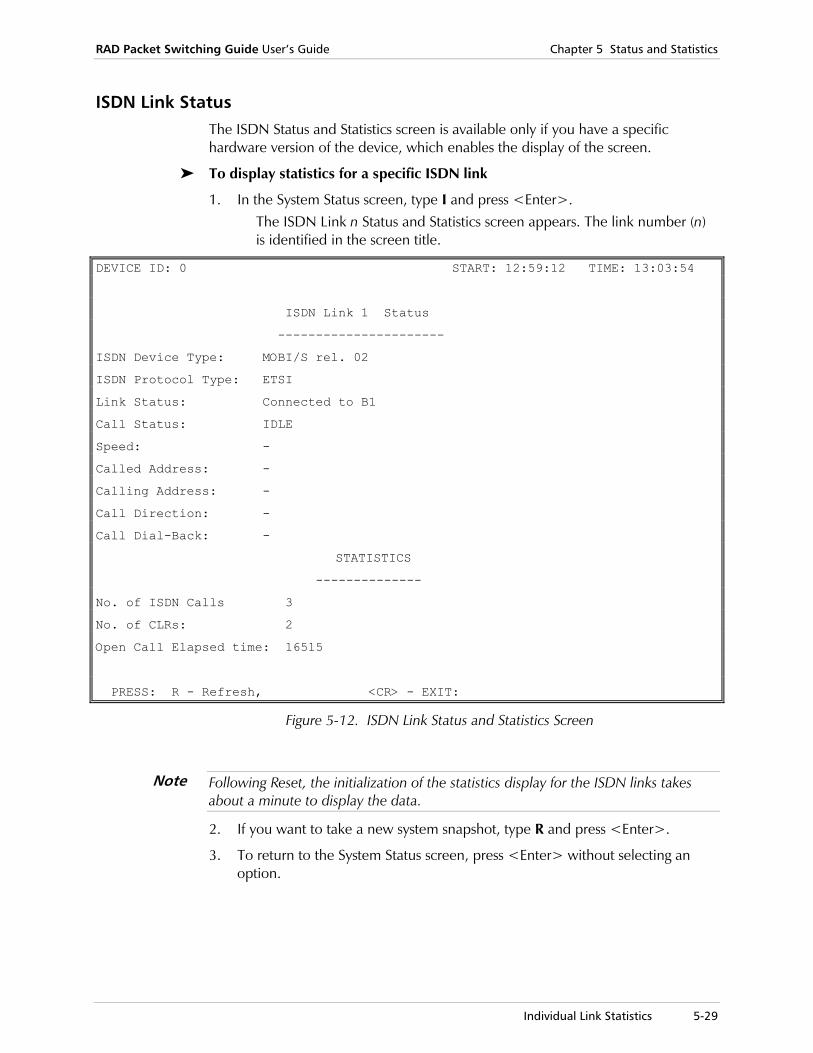
RAD Packet Switching Guide User’s Guide Chapter 5 Status and Statistics
Individual Link Statistics 5-29
ISDN Link Status The ISDN Status and Statistics screen is available only if you have a specific hardware version of the device, which enables the display of the screen.
To display statistics for a specific ISDN link
1. In the System Status screen, type I and press <Enter>. The ISDN Link n Status and Statistics screen appears. The link number (n) is identified in the screen title.
DEVICE ID: 0 START: 12:59:12 TIME: 13:03:54
ISDN Link 1 Status
----------------------
ISDN Device Type: MOBI/S rel. 02
ISDN Protocol Type: ETSI
Link Status: Connected to B1
Call Status: IDLE
Speed: -
Called Address: -
Calling Address: -
Call Direction: -
Call Dial-Back: -
STATISTICS
--------------
No. of ISDN Calls 3
No. of CLRs: 2
Open Call Elapsed time: 16515
PRESS: R - Refresh, <CR> - EXIT:
Figure 5-12. ISDN Link Status and Statistics Screen
Following Reset, the initialization of the statistics display for the ISDN links takes about a minute to display the data.
2. If you want to take a new system snapshot, type R and press <Enter>.
3. To return to the System Status screen, press <Enter> without selecting an option.
Note
Chapter 5 Status and Statistics RAD Packet Switching Guide User’s Guide
5-30 Individual Link Statistics
ISDN Link Status and Statistics Parameters
The ISDN Link n Status and Statistics screen displays the following information:
Device ID The identification of the device (defined through the System Parameters Screen).
Start Time and Current Time
The screen shows the current time and date, and the starting time and date for the collection of the statistical data displayed by the device.
The starting time is the later of the following events:
• The time the device has been turned on (or reset).
• The time the statistics counters were reset, using the SystemControl menu.
ISDN Device Type
Type of the ISDN device.
ISDN Protocol Type
Type of the ISDN protocol to be used by the link.
Possible values: ETSI, NTT Leased
Link Status The channel to which the ISDN link is connected:
Possible values: B1, B2, or Not Connected.
Call Status Shows the status of the current ISDN call.
Possible values:
Active An ISDN call is currently open.
Idle No call is currently open.
Initiating The device is initiating a call.
Connecting The device is in the process of connecting a call with the other side.
Disconnecting The device is in the process of disconnecting a call.
Speed Shows the data rate of the currently open call.
Possible values: 64 Kbps and 56 Kbps
Called Address ISDN address that the device called when it initiated an ISDN session.
Calling Address ISDN address of the source of an incoming call.
Call Direction Direction of the current open call (incoming or outgoing).
Call Dial-Back ISDN address of a destination that will be called by the device when it receives an ISDN call.
No. of ISDN calls Number of ISDN calls transferred through the link since the link was activated.
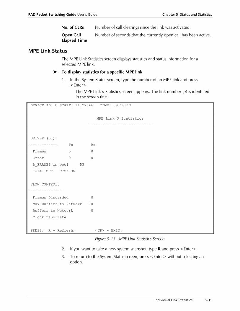
RAD Packet Switching Guide User’s Guide Chapter 5 Status and Statistics
Individual Link Statistics 5-31
No. of CLRs Number of call clearings since the link was activated.
Open Call Elapsed Time
Number of seconds that the currently open call has been active.
MPE Link Status The MPE Link Statistics screen displays statistics and status information for a selected MPE link.
To display statistics for a specific MPE link
1. In the System Status screen, type the number of an MPE link and press <Enter>.
The MPE Link n Statistics screen appears. The link number (n) is identified in the screen title.
DEVICE ID: 0 START: 11:27:46 TIME: 09:18:17
MPE Link 3 Statistics
-----------------------------
DRIVER (L1):
------------- Tx Rx
Frames 0 0
Error 0 0
R_FRAMES in pool 53
Idle: OFF CTS: ON
FLOW CONTROL:
---------------
Frames Discarded 0
Max Buffers to Network 10
Buffers to Network 0
Clock Baud Rate
PRESS: R - Refresh, <CR> - EXIT:
Figure 5-13. MPE Link Statistics Screen
2. If you want to take a new system snapshot, type R and press <Enter>.
3. To return to the System Status screen, press <Enter> without selecting an option.

Chapter 5 Status and Statistics RAD Packet Switching Guide User’s Guide
5-32 Individual Link Statistics
MPE Link Statistics Parameters
The MPE Link n Statistics screen displays the following information:
Device ID The identification of the device (defined through the System Parameters Screen).
Start Time and Current Time
The screen shows the current time and date, and the starting time and date for the collection of the statistical data displayed by the device.
The starting time is the later of the following events:
• The time the device has been turned on (or reset).
• The time the statistics counters were reset, using the SystemControl menu.
Driver (L1) Summary of layer 1 statistics:
Frames Total number of frames transmitted and received by the link.
Error Total number of frames with errors transmitted and received by the link.
R_FRAMES in Pool Number of free buffers that can receive data. If the value is below 2, the link status is defined as busy.
IDLE State of the link: OFF - The link is active (normal traffic condition). ON - The link is idle (held continuously at MARK).
CTS State of the link’s CTS signal. ON - CTS signal is active (normal traffic condition). OFF - CTS signal is off.
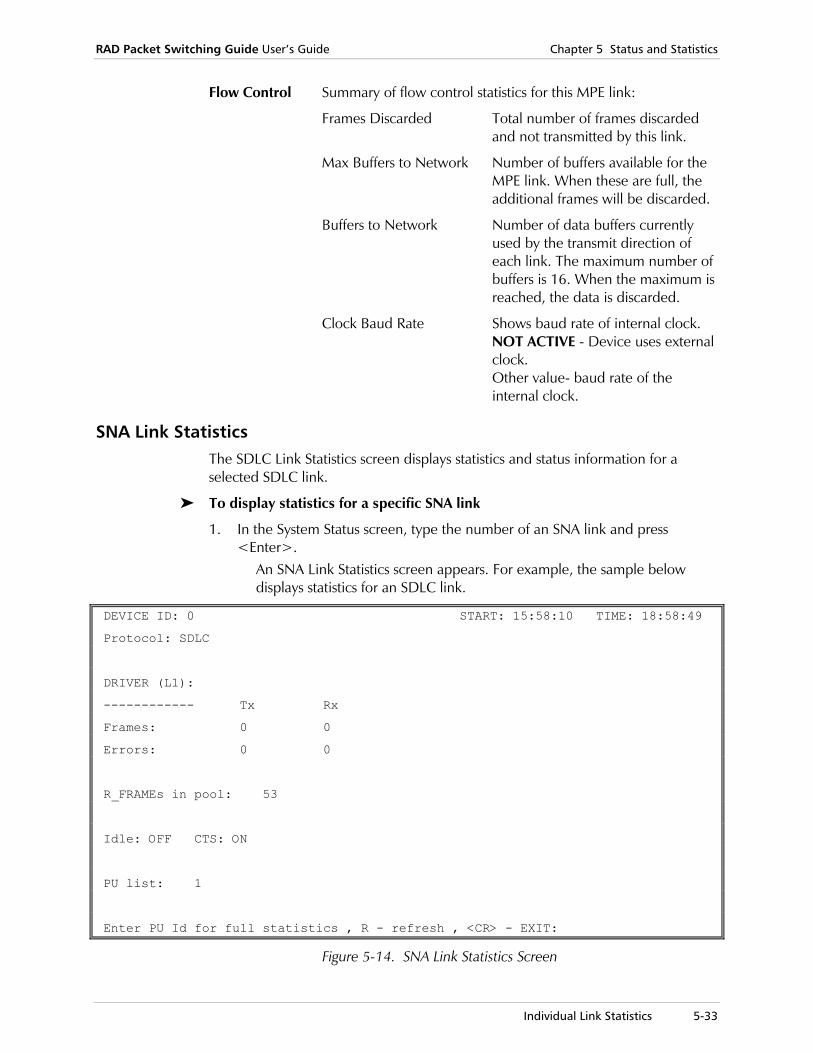
RAD Packet Switching Guide User’s Guide Chapter 5 Status and Statistics
Individual Link Statistics 5-33
Flow Control Summary of flow control statistics for this MPE link:
Frames Discarded Total number of frames discarded and not transmitted by this link.
Max Buffers to Network Number of buffers available for the MPE link. When these are full, the additional frames will be discarded.
Buffers to Network Number of data buffers currently used by the transmit direction of each link. The maximum number of buffers is 16. When the maximum is reached, the data is discarded.
Clock Baud Rate Shows baud rate of internal clock. NOT ACTIVE - Device uses external clock. Other value- baud rate of the internal clock.
SNA Link Statistics The SDLC Link Statistics screen displays statistics and status information for a selected SDLC link.
To display statistics for a specific SNA link
1. In the System Status screen, type the number of an SNA link and press <Enter>.
An SNA Link Statistics screen appears. For example, the sample below displays statistics for an SDLC link.
DEVICE ID: 0 START: 15:58:10 TIME: 18:58:49
Protocol: SDLC
DRIVER (L1):
------------ Tx Rx
Frames: 0 0
Errors: 0 0
R_FRAMEs in pool: 53
Idle: OFF CTS: ON
PU list: 1
Enter PU Id for full statistics , R - refresh , <CR> - EXIT:
Figure 5-14. SNA Link Statistics Screen
Chapter 5 Status and Statistics RAD Packet Switching Guide User’s Guide
5-34 Individual Link Statistics
2. If you want, do any of the following: To take a new system snapshot, type R and press <Enter>.
To open the PU ID statistics screen for the PU that contains this link, type the PU ID number you want and press <Enter>. For more information about the PU statistic parameters, see PU Statistics on page 5-35.
3. To return to the System Status screen, press <Enter> without selecting an option.
SNA Link Statistics Parameters
The SNA Link Statistics screen displays the following information:
Device ID The identification of the device (defined through the System Parameters Screen).
Start Time and Current Time
The screen shows the current time and date, and the starting time and date for the collection of the statistical data displayed by the device.
The starting time is the later of the following events:
• The time the device has been turned on (or reset).
• The time the statistics counters were reset, using the SystemControl menu.
Protocol Layer 3 protocol used by the link.
Driver (L1) Summary of layer 1 statistics:
Frames Total number of frames transmitted and received by the link.
Error Total number of frames with errors transmitted and received by the link.
R_FRAMES in Pool Number of free buffers that can receive data. If the value is below 2, the link status is defined as busy.
IDLE State of the link: OFF - The link is active (normal traffic condition). ON - The link is idle (held continuously at MARK).
CTS State of the link’s CTS signal. ON - CTS signal is active (normal traffic condition). OFF - CTS signal is off.
PU List Existing PUs for the selected link.

RAD Packet Switching Guide User’s Guide Chapter 5 Status and Statistics
Individual Link Statistics 5-35
PU Statistics
In the SNA Link Statistics screen, type the PU ID number you want and press <Enter> to open an individual SNA PU ID statistics screen. The screen displays the statistics from the two interfaces that comprise the selected PU. The statistic parameters for the interfaces vary according to the protocol of the interface: SDLC, QLLC, or LLC2.
DEVICE ID: 0 START: 15:58:10 TIME: 19:03:34
SNA PU Number: 1
SDLC statistics LLC2 statistics
Link 4 Link 3
Address : 1 Address : 4/4/16(BNN)
NRM status : NOT SYNC NRM status : NOT SYNC
Flow/c status: No RNR Flow/c status: No RNR
Upper state : Outcon_pend Upper state : Idle
Lower state : Disconnected Lower state : Disconnected
Link role : Secondary Link role : Primary
Tx | Rx Tx | Rx
I frames : 0 | 0 I frames : 0 | 0
SNRM frames: 0 | 0 SABME frame: 0 | 0
XID frames : 0 | 0 XID frames : 0 | 0
DISC frames: 0 | 0 DISC frames: 0 | 0
DM frames : 0 | 0 DM frames : 0 | 0
RNR frames : 0 | 0 RNR frames : 0 | 0
FRMR frames: 0 | 0 FRMR frames: 0 | 0
REJ frames : 0 | 0 REJ frames : 0 | 0
Retransmits: 0 | 0 Retransmits: 0 | 0
TEST Frames: 0 | 0
PRESS: R - Refresh, <CR> - EXIT:
Figure 5-15. SNA PU Statistics Screen
Chapter 5 Status and Statistics RAD Packet Switching Guide User’s Guide
5-36 Individual Link Statistics
The SNA PU Statistics screen shows the following information:
Device ID The identification of the device (defined through the System Parameters Screen).
Start Time and Current Time
The screen shows the current time and date, and the starting time and date for the collection of the statistical data displayed by the device.
The starting time is the later of the following events:
• The time the device has been turned on (or reset).
• The time the statistics counters were reset, using the SystemControl menu.
Address PU address (SDLC), X.25 link station address (QLLC), or DLCI (LLC2/FR) associated with this PU interface.
NRM Status Indicates if the link is in Normal Response Mode (Sync) or not (Not Sync).
Flow/c Status Flow control status of this PU interface. The possible values are NO RNR, Transmit, Receive and Rx and Tx.
Upper State Internal DLPI state of the connection.
Lower State Internal SDLC, QLLC/X.25, or LLC2/FR state of the connection.
Link Role Role of the PU in the specific interface.
The SNA PU Statistics screen contains additional groups of protocol-specific statistics for SDLC, QLLC/X.25, and LLC2/FR interfaces. The groups display the total numbers of transmit (Tx) and receive (Rx) frames or packets passing through the PU’s interfaces.

RAD Packet Switching Guide User’s Guide Chapter 5 Status and Statistics
Individual Link Statistics 5-37
Ethernet Link Statistics The Ethernet Port Statistics screen displays statistics and status information for a selected Ethernet link.
To display statistics for a specific Ethernet link
1. In the System Status screen, type the number of an Ethernet link and press <Enter>.
The Ethernet Port n Statistics screen appears. The link number (n) is identified in the screen title.
DEVICE ID: 0 START: 15:58:10 TIME: 18:53:25
ETHERNET Port 1 Statistics
-----------------------------------
Operation Mode Free Buffers in Rx pool: 53
--------------
IP : DISABLED
LLC2 : ENABLED
Bridge : DISABLED
Tx frames Rx frames
Total frames : 2427 0
IP statistics : 0 0
LLC2 statistics : 2427 0
Bridge statistics : 0 0
Frames discarded by filter : 0
Press: R - Refresh <CR> - EXIT:
Figure 5-16. Ethernet Port Statistics Screen
2. If you want to take a new system snapshot, type R and press <Enter>.
3. To return to the System Status screen, press <Enter> without selecting an option.
Chapter 5 Status and Statistics RAD Packet Switching Guide User’s Guide
5-38 Individual Link Statistics
Ethernet Link Statistics Parameters
The Ethernet Port n Statistics screen displays the following information:
Device ID The identification of the device (defined through the System Parameters Screen).
Start Time and Current Time
The screen shows the current time and date, and the starting time and date for the collection of the statistical data displayed by the device.
The starting time is the later of the following events:
• The time the device has been turned on (or reset).
• The time the statistics counters were reset, using the SystemControl menu.
Operation Mode Mode of operation for handling the transfer of data over the Ethernet link. The available types are IP, LLC2, or Bridge.
Enabled Specific operation mode is active.
Disabled Specific operation mode is not active.
Free Buffers in RX Pool
Number of available buffers in the receive pool.
Total Frames Total number of frames transmitted and received in the selectedlink since the start of the current count.
IP, LLC2, & Bridge Statistics
Number of frames transmitted and received in the selected link since the start of the current count, according to the Ethernet operation mode.
Frames Discarded by Filter
Number of frames that were discarded because they did not match the criteria defined in the Bridging Filter Table (see Ethernet Link Configuration in Chapter 2).

RAD Packet Switching Guide User’s Guide Chapter 5 Status and Statistics
Displaying a Protocol Cut 5-39
5.4 Displaying a Protocol Cut
A protocol cut is a screen that displays the statistics for all links that use Frame Relay, SNA or IP protocol.
To open a protocol cut screen
1. In the System Status screen, select P (Protocols) and press <Enter>. The Protocols menu appears.
Protocols
------------
1) FRAME RELAY
2) SNA
3) IP
CR) Exit
Select:
Figure 5-17. Protocols Menu
2. Select one of the available protocol options and press <Enter>. The appropriate global statistics screen appears.
3. To return to the System Status screen, press <Enter> without selecting an option.

Chapter 5 Status and Statistics RAD Packet Switching Guide User’s Guide
5-40 Displaying a Protocol Cut
Frame Relay Protocol Cut
The Frame Relay Global Statistics screen displays statistics for all the device’s Frame Relay links.
To display statistics for all the device’s FR links
1. In the System Status screen, select P (Protocols) and press <Enter>. The Protocols menu appears.
2. Select 1 (Frame Relay) and press <Enter>. The Frame Relay Global Statistics screen appears.
DEVICE ID: 0 START: 15:58:10 TIME: 18:39:40
FRAME RELAY global Statistics
-----------------------------------
Number of ports : 0
Ports list : NONE
Number of DLCIs : 0
Number of funnels: 0
Discarded frames : 0
Tx Rx
Frames : 0 0
LMI frames : 0 0
ANSI/Q.933 frames: 0 0
CLLM frames : 0 0
Congestions : 0 0
DE frames : 0 0
FECN frames : 0 0
BECN frames : 0 0
Enter Port Number to Zoom, R - Refresh, <CR> - EXIT:
Figure 5-18. Frame Relay Global Statistics Screen
3. If you want, do any of the following: To take a new system snapshot, type R and press <Enter>.
To open an individual FR port statistics screen, type the FR link number you want and press <Enter>.
4. To return to the Protocols menu, press <Enter> without selecting an option.

RAD Packet Switching Guide User’s Guide Chapter 5 Status and Statistics
Displaying a Protocol Cut 5-41
Frame Relay Global Statistics Parameters
The Frame Relay Global Statistics screen displays the following information:
Device ID The identification of the device (defined through the System Parameters Screen).
Start Time and Current Time
The screen shows the current time and date, and the starting time and date for the collection of the statistical data displayed by the device.
The starting time is the later of the following events:
• The time the device has been turned on (or reset).
• The time the statistics counters were reset, using the SystemControl menu.
Number of Ports Number of Frame Relay ports in the device.
Ports List List of Frame Relay ports in the device.
Number of DLCIs
Number of existing DLCIs for all the Frame Relay ports.
Number of Funnels
Number of existing Funnels for all the Frame Relay ports.
Discarded Frames
Total number of frames discarded by all the Frame Relay ports.
Frames Total number of frames transmitted and received by all the Frame Relay ports.
LMI Frames Total number of LMI protocol frames transmitted and received by all the Frame Relay ports.
ANSI Frames Total number of ANSI protocol frames transmitted and received by all the Frame Relay ports.
CLLM Frames Total number of CLLM protocol frames transmitted and received by all the Frame Relay ports.
Congestions Total number of congested frames transmitted and received by all the Frame Relay ports.
DE Frames Total number of frames with DE bit set that were transmitted and received by all the Frame Relay ports.
FECN Frames Total number of frames with FECN bit set that were transmitted and received by all the Frame Relay ports.
BECN Frames Total number of frames with BECN bit set that were transmitted and received by all the Frame Relay ports.

Chapter 5 Status and Statistics RAD Packet Switching Guide User’s Guide
5-42 Displaying a Protocol Cut
SNA Protocol Cut
The SNA Global PU Statistics screen displays statistics for all the device’s SNA links.
To display statistics for all the device’s SNA links
1. In the System Status screen, select P (Protocols) and press <Enter>. The Protocols menu appears.
2. Select 2 (SNA) and press <Enter>. The SNA Global PU Statistics screen appears.
DEVICE ID: 0 START: 15:58:10 TIME: 18:39:40
SNA global PU Statistics
---------------------------------------------------------------------------------
PU| I N T E R F A C E A | I N T E R F A C E B
Id|Prot|Lnk| Address |NRM|F/C|I pkt|Prot|Lnk| Address |NRM|F/C|I pkt
--|----|---|--------------|---|---|------|----|---|--------------|---|---|------
Enter PU Id for full statistics , R - Refresh , <CR> - EXIT:
Figure 5-19. SNA Global PU Statistics Screen
3. If you want, do any of the following: To take a new system snapshot, type R and press <Enter>.
To open an individual PU statistics screen, type the PU ID number you want and press <Enter>.
4. To return to the Protocols menu, press <Enter> without selecting an option.
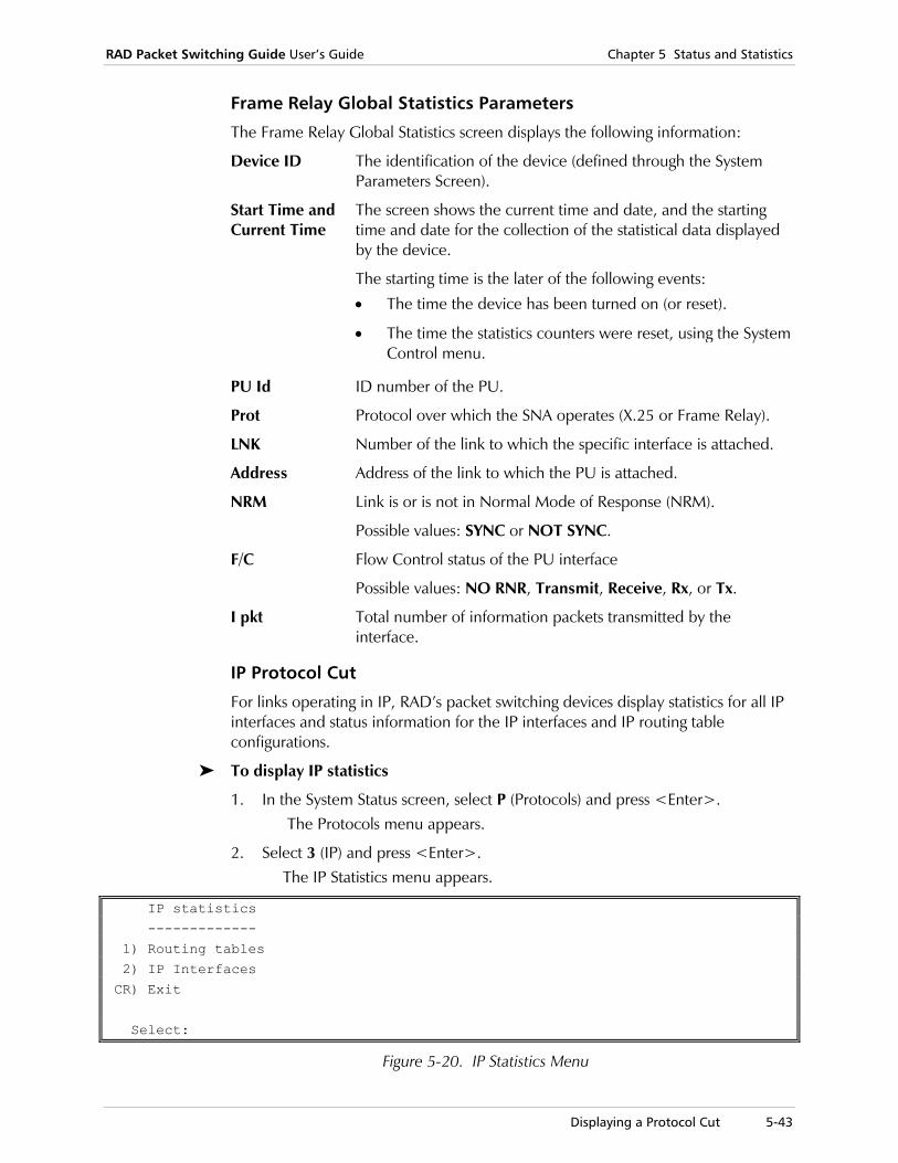
RAD Packet Switching Guide User’s Guide Chapter 5 Status and Statistics
Displaying a Protocol Cut 5-43
Frame Relay Global Statistics Parameters
The Frame Relay Global Statistics screen displays the following information:
Device ID The identification of the device (defined through the System Parameters Screen).
Start Time and Current Time
The screen shows the current time and date, and the starting time and date for the collection of the statistical data displayed by the device.
The starting time is the later of the following events:
• The time the device has been turned on (or reset).
• The time the statistics counters were reset, using the SystemControl menu.
PU Id ID number of the PU.
Prot Protocol over which the SNA operates (X.25 or Frame Relay).
LNK Number of the link to which the specific interface is attached.
Address Address of the link to which the PU is attached.
NRM Link is or is not in Normal Mode of Response (NRM).
Possible values: SYNC or NOT SYNC.
F/C Flow Control status of the PU interface
Possible values: NO RNR, Transmit, Receive, Rx, or Tx.
I pkt Total number of information packets transmitted by the interface.
IP Protocol Cut
For links operating in IP, RAD’s packet switching devices display statistics for all IP interfaces and status information for the IP interfaces and IP routing table configurations.
To display IP statistics
1. In the System Status screen, select P (Protocols) and press <Enter>. The Protocols menu appears.
2. Select 3 (IP) and press <Enter>. The IP Statistics menu appears.
IP statistics
-------------
1) Routing tables
2) IP Interfaces
CR) Exit
Select:
Figure 5-20. IP Statistics Menu

Chapter 5 Status and Statistics RAD Packet Switching Guide User’s Guide
5-44 Displaying a Protocol Cut
3. Type the number of a status or statistics option and press <Enter>. The appropriate Status/Statistics screen appears.
4. To return to the Protocols menu, press <Enter> without selecting an option.
IP Routing Tables Status
The IP Routing Table Status screen displays current operational information about the device’s IP routing configurations.
To display the Routing Table status
1. In the IP Statistics Menu, select 1 (Routing Tables) and press <Enter>. The IP Routing Table Status screen appears.
---------------+---------------+-----------------------+--+---------------+--+
IP Address | IP Mask | Destination |Mt| Next Hop |St|
---------------+---------------+-----------------------+--+---------------+--+
Press <CR> to Continue, <Q> to QUIT
Figure 5-21. IP Routing Table Status Screen
2. To view more routing table entries, press <Enter>.
3. To return to the IP Statistics menu, type Q.
Routing Table Parameters
The IP Routing Table Status screen displays the following information:
IP Address IP address of the destination device in this entry.
IP Mask Significant bits of the IP address for determining destinations.
Destination Logical port/channel destination of this entry.
Mt Metric of this entry for communicating with the destination defined by the parameter, IP Address.
Next Hop IP address of a workstation (such as a gateway out of the LAN) that transfers data out of the local LAN towards the destination.
St IP Interface is either static (Y) or dynamic (N).
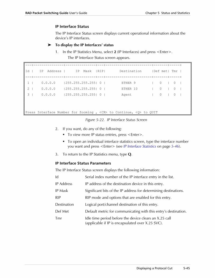
RAD Packet Switching Guide User’s Guide Chapter 5 Status and Statistics
Displaying a Protocol Cut 5-45
IP Interface Status
The IP Interface Status screen displays current operational information about the device’s IP interfaces.
To display the IP Interfaces’ status
1. In the IP Statistics Menu, select 2 (IP Interfaces) and press <Enter>. The IP Interface Status screen appears.
---+---------------+---------------+---+-----------------------+-------+-----+
Id | IP Address | IP Mask |RIP| Destination |Def met| Tmr |
---+---------------+---------------+---+-----------------------+-------+-----+
1 | 0.0.0.0 |255.255.255.255| 0 | ETHER 9 | 0 | 0 |
2 | 0.0.0.0 |255.255.255.255| 0 | ETHER 10 | 0 | 0 |
3 | 0.0.0.0 |255.255.255.255| 0 | Agent | 0 | 0 |
Press Interface Number for Zooming , <CR> to Continue, <Q> to QUIT
Figure 5-22. IP Interface Status Screen
2. If you want, do any of the following: To view more IP status entries, press <Enter>.
To open an individual interface statistics screen, type the interface number you want and press <Enter> (see IP Interface Statistics on page 5-46).
3. To return to the IP Statistics menu, type Q.
IP Interface Status Parameters
The IP Interface Status screen displays the following information:
Id Serial index number of the IP interface entry in the list.
IP Address IP address of the destination device in this entry.
IP Mask Significant bits of the IP address for determining destinations.
RIP RIP mode and options that are enabled for this entry.
Destination Logical port/channel destination of this entry.
Def Met Default metric for communicating with this entry’s destination.
Tmr Idle time period before the device clears an X.25 call (applicable if IP is encapsulated over X.25 SVC).

Chapter 5 Status and Statistics RAD Packet Switching Guide User’s Guide
5-46 Displaying a Protocol Cut
IP Interface Statistics
The IP Interface Statistics screen displays transmission and reception traffic information for a selected IP interface.
To display the IP Interfaces’ status
1. In the IP Statistics Menu, select 2 (IP Interfaces) and press <Enter>. The IP Interface Status screen appears.
2. Type the number of the IP interface whose statistics you want to view and press <Enter>.
The IP Interface n Status screen appears. The interface number (n) is identified in the screen title.
IP Interface 1 Statistics
-----------------------------
Status: ACTIVE
IP Address :0.0.0.0 IP Mask :255.255.255.255
Destination : ETHER 9
General Counters
----------------
Rx Frames ................... 0
Rx Frames with TTL Expired .. 0
Rx Frames with no Route ..... 0
Tx Frames ................... 0
Buffers on Tx Queue ......... 0
Tx discarded frames ......... 0
RIP Counters
------------
Rx Frames ................... 0
Tx Frames ................... 0
RIP messages waiting to net . 0
Press: R - Refresh, <CR> - EXIT
Figure 5-23. IP Interface Statistics screen
3. If you want to take a new system snapshot, type R and press <Enter>.
4. To return to the IP Interface Status screen, press <Enter>.
RAD Packet Switching Guide User’s Guide Chapter 5 Status and Statistics
Displaying a Protocol Cut 5-47
IP Interface Statistics Parameters
The IP Interface n Statistics screen displays the following information:
IP Address IP address of the destination device in this entry.
IP Mask Significant bits of the IP address for determining destinations.
Destination Logical port/channel destination of this entry.
General Counters
Reception and transmission traffic information in the selected IP interface.
Rx Frames Total number of frames received by the interface.
Rx Frames with TTL Expired Total number of frames received by the interface, which were discarded because the TTL (Time To Live) bit expired.
Rx Frames with no Route Total number of frames received by the interface, which were discarded because they did not include routing information.
Tx Frames Total number of frames transmitted in the interface.
Buffers on Tx Queue Total number of buffers waiting for transmission from the interface.
Tx Discarded Frames Total number of frames that werediscarded from the interface.
RIP Counters Reception and transmission traffic information over the attachedRIP network through the selected IP interface.
Rx Frames Total number of frames received by the interface.
Tx Frames Total number of frames transmitted in the interface.
RIP Messages Waiting to Net Number of RIP messages waiting for transmission from the selected interface.

Chapter 5 Status and Statistics RAD Packet Switching Guide User’s Guide
5-48 Displaying a Protocol Cut

Diagnostics 6-1
Chapter 6 Diagnostics and Troubleshooting This chapter:
• Describes the various diagnostic tests available for testing the device for normal operation
• Provides descriptions of possible operating problems and solutions for troubleshooting them.
6.1 Diagnostics
Diagnostic tests are used to test various parts of the device, parameter settings, and its connections to other network equipment.
The available diagnostic tests are:
• FOX test
• Ping test
• Local and remote loopbacks
• ISDN call check.
To select a diagnostic test
1. In the Main menu, select 3 (Diagnostics). The Diagnostics menu appears.
DIAGNOSTICS MENU
----------------
1) FOX test
2) Send Ping
3) Local Loopback
4) Remote Loopback
5) ISDN Call Check
CR) Exit
Select:
Figure 6-1. Diagnostics Menu

Chapter 6 Diagnostics and Troubleshooting RAD Packet Switching Guide User’s Guide
6-2 Diagnostics
2. Type the number of a diagnostic test and press <Enter>. The appropriate test screen appears.
3. To return to the Main menu, press <Enter> without selecting an option.
FOX Test Use the FOX test to check for proper connection between a terminal and a local or remote channel. This test is applicable for Asynchronous and X.25 applications.
At 1-second intervals, the PAD sends a sentence that contains all the alphanumeric characters to the channel that initiated this test. The sentence must appear on the channel terminal. At the end of each sentence, a sequentially increasing number starting from 000 appears.
The FOX test is used for the following checks:
Local Test Verify proper connection between a terminal and the local PAD (see Figure 6-2a).
Remote Test Verify proper connection of the entire path between a terminal connected to a local device and a remote PAD on the other side of the network (see Figure 6-2b).
APD 8
APD 8 #1
X.25Network
APD 8 #2
a. Local
b. Remote Figure 6-2. FOX Test through a Network

RAD Packet Switching Guide User’s Guide Chapter 6 Diagnostics and Troubleshooting
Diagnostics 6-3
The Local test is done by connecting the terminal to a local command port and then activating the test. To confirm the connection to the local command port, type C0 at the local terminal. From the Main menu, activate the test through the Diagnostics menu.
The Remote test is done by connecting the terminal to a local command port, connecting over a network to the remote Command port, and then activating the test. To confirm the connection to the remote command port, type C[remote address] at the local terminal (for example, C12345678900). From the Main menu, activate the test through the Diagnostics menu.
To run a FOX test
1. In the Diagnostics menu, select 1 (FOX Test) and press <Enter>. The FOX test screen appears.
THE QUICK BROWN FOX JUMPS OVER THE LAZY DOG 0123456789 >>>> TEST....000
THE QUICK BROWN FOX JUMPS OVER THE LAZY DOG 0123456789 >>>> TEST....001
THE QUICK BROWN FOX JUMPS OVER THE LAZY DOG 0123456789 >>>> TEST....002
THE QUICK BROWN FOX JUMPS OVER THE LAZY DOG 0123456789 >>>> TEST....003
Figure 6-3. FOX Screen Test
2. When done, press <Enter> to return to the Diagnostics menu.
Ping Test Use the Ping test to check if the local device communicates with a node or a remote device over an IP network. The device attempts to receive an echo response from a connected address. At 1-second intervals, the device sends a datagram over the network and any response is displayed on the terminal.
The Ping test is a useful tool for locating problems on the network related to failed connections and software problems.
To run a Ping test
1. In the Diagnostics menu, select 2 (Send Ping) and press <Enter>. The Send Ping screen appears.
Send Ping Screen ---------------- The source ip address is the AGENT IP address of the device. 1) Destination IP address ....... [ ] S) Start sending ping. CR) Exit. Select:
Figure 6-4. Send Ping Screen
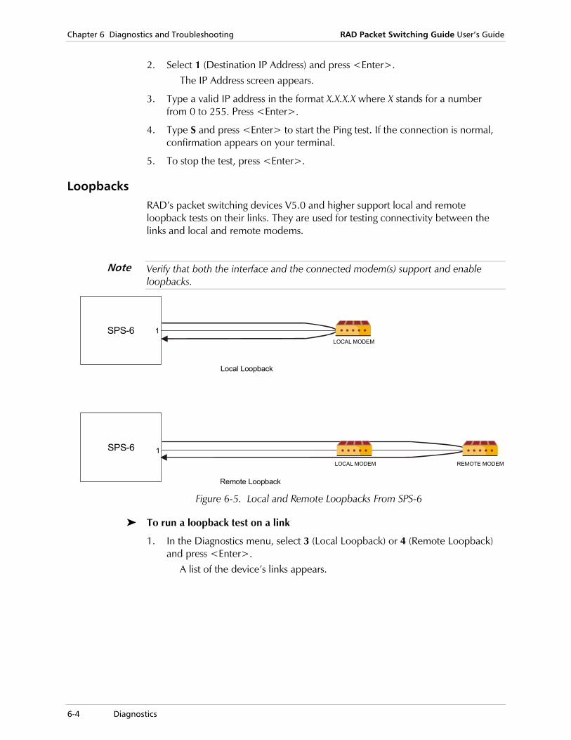
Chapter 6 Diagnostics and Troubleshooting RAD Packet Switching Guide User’s Guide
6-4 Diagnostics
2. Select 1 (Destination IP Address) and press <Enter>. The IP Address screen appears.
3. Type a valid IP address in the format X.X.X.X where X stands for a number from 0 to 255. Press <Enter>.
4. Type S and press <Enter> to start the Ping test. If the connection is normal, confirmation appears on your terminal.
5. To stop the test, press <Enter>.
Loopbacks RAD’s packet switching devices V5.0 and higher support local and remote loopback tests on their links. They are used for testing connectivity between the links and local and remote modems.
Verify that both the interface and the connected modem(s) support and enable loopbacks.
LOCAL MODEM
LOCAL MODEM
1
1
REMOTE MODEM
Local Loopback
Remote Loopback
SPS-6
SPS-6
Figure 6-5. Local and Remote Loopbacks From SPS-6
To run a loopback test on a link
1. In the Diagnostics menu, select 3 (Local Loopback) or 4 (Remote Loopback) and press <Enter>.
A list of the device’s links appears.
Note

RAD Packet Switching Guide User’s Guide Chapter 6 Diagnostics and Troubleshooting
Diagnostics 6-5
2. Type the number of the link on which you want to run the loopback and press <Enter>.
The Loopback Test screen appears.
Starting loopback in 4 seconds. Please wait. Starting loopback in 3 seconds. Please wait. Starting loopback in 2 seconds. Please wait. Starting loopback in 1 seconds. Please wait. Frames Sent ... 0 Frames Received ... 0 Lost Frames ... 0% Frames Sent ... 1 Frames Received ... 0 Lost Frames ... 100% Frames Sent ... 2 Frames Received ... 0 Lost Frames ... 100%
Figure 6-6. Loopback Test Screen
3. To return to the Diagnostics menu, press <Enter>.
ISDN Call Check RAD’s packet switching devices V5.0 and higher support ISDN call test on the ISDN link. The test opens (and closes) an ISDN call to a known destination through selected port without activating higher level protocols, e.g. Frame Relay over ISDN.
To run an ISDN call check
1. In the Diagnostics menu, select 5 (ISDN Call Check) and press <Enter>. The ISDN call check screen appears with ISDN ports only.
+------+-----------------+------
| Link | Outgoing | Sub
|.No. | Address | Addr
+------+-----------------+------
| 1 | |
| 2 | |
| 3 | |
| 4 | |
Update : select link number from the table to update outgoing
address or subaddress
Open call : enter 's', followed by the link number, to start ISDN
check on the specified link
Close call: enter 'e', followed by the link number, to terminate the
ISDN check on the specified link
Exit : enter <CR>
Enter one of the above values or <RETURN> to exit:
Figure 6-7. ISDN Call Check Screen
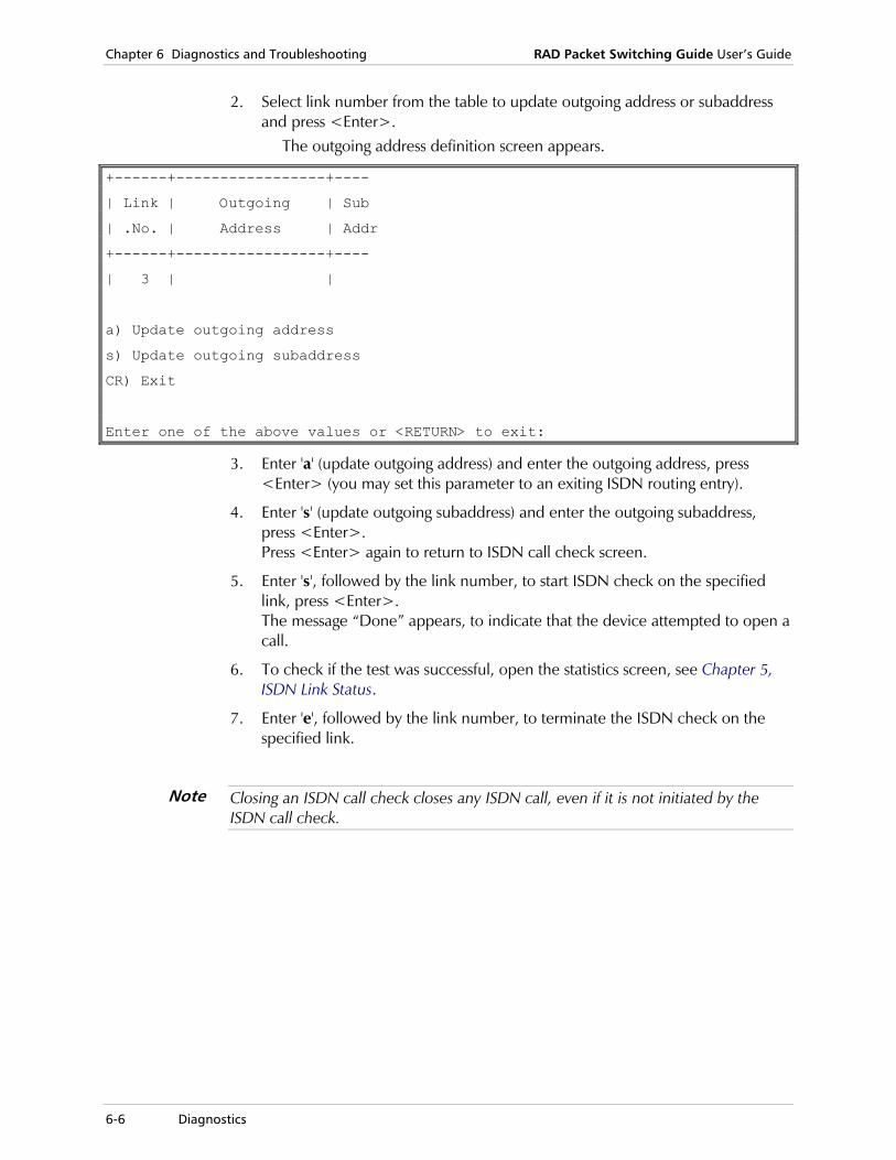
Chapter 6 Diagnostics and Troubleshooting RAD Packet Switching Guide User’s Guide
6-6 Diagnostics
2. Select link number from the table to update outgoing address or subaddress and press <Enter>.
The outgoing address definition screen appears.
+------+-----------------+----
| Link | Outgoing | Sub
| .No. | Address | Addr
+------+-----------------+----
| 3 | |
a) Update outgoing address
s) Update outgoing subaddress
CR) Exit
Enter one of the above values or <RETURN> to exit:
3. Enter 'a' (update outgoing address) and enter the outgoing address, press <Enter> (you may set this parameter to an exiting ISDN routing entry).
4. Enter 's' (update outgoing subaddress) and enter the outgoing subaddress, press <Enter>. Press <Enter> again to return to ISDN call check screen.
5. Enter 's', followed by the link number, to start ISDN check on the specified link, press <Enter>. The message “Done” appears, to indicate that the device attempted to open a call.
6. To check if the test was successful, open the statistics screen, see Chapter 5, ISDN Link Status.
7. Enter 'e', followed by the link number, to terminate the ISDN check on the specified link.
Closing an ISDN call check closes any ISDN call, even if it is not initiated by the ISDN call check.
Note

RAD Packet Switching Guide User’s Guide Chapter 6 Diagnostics and Troubleshooting
Troubleshooting 6-7
6.2 Troubleshooting
Preliminary Checks If a problem occurs, check the following to try to detect it and restore the device to normal operation.
1. Check that the device is powered (PWR indicator is on).
2. Check that all the cables are properly connected.
3. Check that the equipment connected to the device is powered and operates normally.
4. Check the configuration of the device. Verify that the link parameters match the nearest X.25 peer data. In particular, pay attention to your local address and to the transmission mode (DTE or DCE). Verify that your routing table is configured according to your connections.
5. Observe indications and see the following table for corrective actions.
Table 6-1. Troubleshooting
No. Indication Probable Cause Action
1 ERR is on. Problem Turn the device off, then turn it on again or press RESET. IF the ERR indicator remains on, replace the device.
2 TEST is on. Device is in command mode
Check whether the device is being configured, and wait until configuration is completed.
3 For APD and APS: One or more of the MAIN indicators does not light up
Problems in communication link to a remote device
Check whether communication equipment is powered and properly connected. Then use the troubleshooting procedures to identify fault location.
(The corresponding SYNC may also flash).
Device problem Turn the device off,, then turn it on again or press RESET. If the ERR indicator turns on, replace the device.
4 One or more of the SYNC indicators flashes continuously (The
X.25 DTE/DCE peer not operational
Check whether the X.25 DTE/DCE peer is turned on, and operates normally. Verify that your DTE/DCE parameter is configured to match the nearest X.25 peer data.
corresponding MAIN indicator is on).
Problems in communication link to the X.25 DTE/DCE peer
Check whether communication equipment is turned on and properly connected. Then use the systematic troubleshooting procedures (see Systematic Troubleshooting Procedures on page 6-8) to identify fault location.

Chapter 6 Diagnostics and Troubleshooting RAD Packet Switching Guide User’s Guide
6-8 Troubleshooting
Table 6-1. Troubleshooting (Cont.)
No. Indication Probable Cause Action
5 OVF is on. Buffer full One of the DTE units connected to the device does not respond to flow control commands. Check that all the DTE’s have a flow control option, and that flow control is properly configured.
6 One or more channel indicators are permanently off.
No traffic on channel If traffic is expected, but no activity is indicated, check DTE equipment and its connections.
Device problem Press the RESET push-button,, and/or turn the device off, then on again. Verify that during power up the self-test sequence causes the channel indicators to turn on for a short interval. If the ERR indicator is on, replace the device.
Systematic Troubleshooting Procedures The device is usually part of a complex communication system that includes many components. In case of a problem, the first action must be to find the component that causes the problem, so it can be replaced.
A recommended system troubleshooting sequence that uses capabilities is given below. When performing this sequence, always correct any problem detected in an earlier step before continuing to the next step.
User’s Equipment • Check that the local user’s equipment connected to the channels is operating
properly by performing self-test and other test procedures recommended in its user's manual. Verify that your terminal settings are correct.
Self-Test
1. Reset the device or turn it off and on again, and observe the test indications.
2. Observe the herald message on your monitor.
3. If the ERR indicator turns on after the self-test, reload the factory default settings (System Control menu, option 10); if the problem recurs, replace the device.

RAD Packet Switching Guide User’s Guide Chapter 6 Diagnostics and Troubleshooting
Troubleshooting 6-9
Connections to Local User’s Equipment • Check that the local user’s equipment receives the echo generated by the
channel.
If no echo is received, check that the compatible channel indicator is lit for each key that is pressed on the keyboard.
If the currently used profile does not allow an echo, check that the current profile enables echoing.
Type PAR?2 and receive the response PAR2:1 (see PAD Control in Chapter 4). If you can’t get a response, type SET?2:1 to allow an echo.
If the user does not receive an echo, the problem is probably in the cables that connect the user’s equipment to the channel, in the user’s equipment itself or in the device. Correct local loopback connections are shown in the following figure:
Channel 1
Channel 3
Channel 2
SPS-8, SPS-12USER DTE
Figure 6-8. Local Loopback Connections
Chapter 6 Diagnostics and Troubleshooting RAD Packet Switching Guide User’s Guide
6-10 Troubleshooting
Local Call Test • Make a local call between two terminals connected to two channels.
If the call cannot be connected, the device is probably defective.
X.25 Synchronization Test
1. Check if all the SYNC indicators of the device light steadily.
2. If an indicator flashes, check for that link: The link configuration parameters, especially the DTE/DCE setting.
If modems serving the links operate properly and are synchronized (see the modem’s user’s manual). Use the Individual Link statistics screen (see X.25 Link Statistics in Chapter 5) to check the state of the link CD and CTS signals.
Test Call
1. Verify that the link parameters match the nearest X.25 peer data. Pay attention in particular to your local address and to the transmission mode (DTE or DCE).
2. Verify that your routing table is configured according to your connections. Make a test call to the remote destination. If the call fails, check the clearing cause (see PAD Command Set in Chapter 4).
X.25 Protocol 7-1
Chapter 7 Protocols This chapter:
• Provides information explaining the protocols, and describes typical applications
• Explains basic terms that are required to understand the PAD and Switch functions. The protocols are presented in detail, setting out the information path from the starting point (the user) until the destination point (the remote end).
7.1 X.25 Protocol
Structure of X.25 Communication Systems
Basic Concepts of Packetized Transmission
The transmission of the data generated by the users (subscribers) of an X.25 packet-switching network is performed in discrete units, called “packets”. Packets comprise a header containing user identification, call control and routing information, a user data field, and a control field that indicates the end of the packet.
The X.25 transmission facility queues user packets, and transmits them to the destination indicated in the packet header. Effectively, this connects the sending and receiving DTEs by a data circuit. To distinguish between regular circuits (i.e., circuits that provide a physical connection between the DTEs, a connection that is available exclusively and continuously to the two communicating DTEs) and this type of connection, the resulting packet-switched circuit is called a virtual circuit. Similarly, the calls are called “virtual calls”.
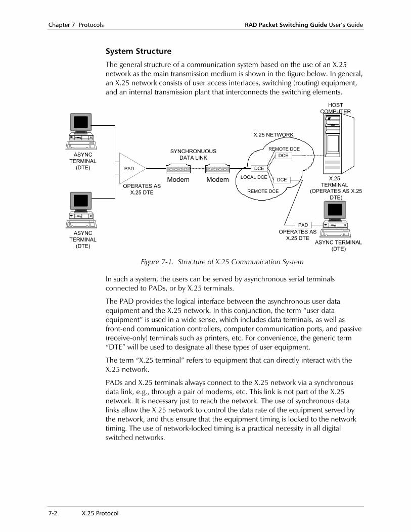
Chapter 7 Protocols RAD Packet Switching Guide User’s Guide
7-2 X.25 Protocol
System Structure
The general structure of a communication system based on the use of an X.25 network as the main transmission medium is shown in the figure below. In general, an X.25 network consists of user access interfaces, switching (routing) equipment, and an internal transmission plant that interconnects the switching elements.
Modem Modem
DCE
DCE
DCE
PAD
REMOTE DCE
REMOTE DCE
LOCAL DCE
ASYNCTERMINAL
(DTE)
ASYNCTERMINAL
(DTE)
PAD
SYNCHRONUOUSDATA LINK
X.25 NETWORK
OPERATES ASX.25 DTE (OPERATES AS X.25
DTE)
X.25TERMINAL
HOSTCOMPUTER
ASYNC TERMINAL(DTE)
OPERATES ASX.25 DTE
Figure 7-1. Structure of X.25 Communication System
In such a system, the users can be served by asynchronous serial terminals connected to PADs, or by X.25 terminals.
The PAD provides the logical interface between the asynchronous user data equipment and the X.25 network. In this conjunction, the term “user data equipment” is used in a wide sense, which includes data terminals, as well as front-end communication controllers, computer communication ports, and passive (receive-only) terminals such as printers, etc. For convenience, the generic term “DTE” will be used to designate all these types of user equipment.
The term “X.25 terminal” refers to equipment that can directly interact with the X.25 network.
PADs and X.25 terminals always connect to the X.25 network via a synchronous data link, e.g., through a pair of modems, etc. This link is not part of the X.25 network. It is necessary just to reach the network. The use of synchronous data links allow the X.25 network to control the data rate of the equipment served by the network, and thus ensure that the equipment timing is locked to the network timing. The use of network-locked timing is a practical necessity in all digital switched networks.

RAD Packet Switching Guide User’s Guide Chapter 7 Protocols
X.25 Protocol 7-3
X.25 DTE and DCE
To obtain service from an X.25 network, it is necessary to use the Link Access Protocol (LAP) specified by ITU Rec. X.25, in its balanced (LAPB) version. The protocol specifies the exchange of commands and responses between the various system components. In a balanced system, commands can be issued by either side.
The X.25 protocol defines, for each system component, what are the commands that will be accepted, and what will be the response to each command. To differentiate between the user equipment and the X.25 network equipment, ITU Rec. X.25 defines two types of equipment:
• X.25 data terminal equipment (X.25 DTE).
• X.25 data circuit-terminating equipment (X.25 DCE).
The X.25 DTE is always on the user side, and the X.25 DCE is always on the network side. Each system component that transmits an X.25 protocol data unit (PDU) (command or response) identifies itself as DTE or DCE (in fact, it also identifies the type of X.25 PDU).
ITU Rec. X.25 specifies that an X.25 DTE communicates with its X.25 DCE peer and vice versa. In a switched X.25 network, the local X.25 DCE must provide all the services that may be needed by the X.25 DTE for call setup, etc. (the X.25 DTE does not have direct access to the entities that form the X.25 network).
PADs can also operate in point-to-point connections that do not use the services of an X.25 network (i.e., two PADs can be directly connected by a synchronous transmission link). In such configurations, the two units must use different X.25 transmission modes, i.e., one must be configured as an X.25 DTE and the other as an X.25 DCE.
X.25 Packet Switched Protocol
Organization of X.25 Protocol
The protocol specified by ITU Rec. X.25 covers three aspects (or “layers”, in the terminology of the OSI data transmission model) of the data transmission process:
• Layer 1 - the physical layer
• Layer 2 - the link (or frame) layer
• Layer 3 - the packet layer.
The integration of the three layers to provide end-to-end service is illustrated in the figure below.
• The packet layer processes the call requests made by the users and provides the call setup information, as well as user data, to the frame layer.
• The frame layer organizes the packets provided by the packet layer in frames that can be reliably transmitted through the physical link.
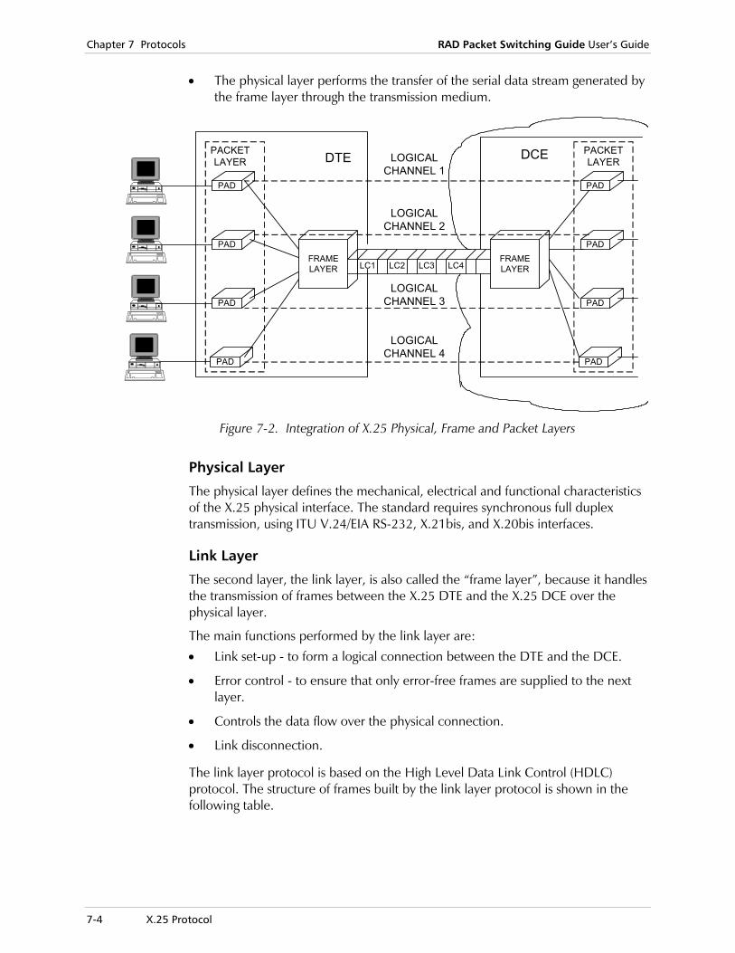
Chapter 7 Protocols RAD Packet Switching Guide User’s Guide
7-4 X.25 Protocol
• The physical layer performs the transfer of the serial data stream generated by the frame layer through the transmission medium.
PAD
PAD
PACKETLAYER
FRAMELAYER
FRAMELAYERLC1 LC2 LC4LC3
PAD
PAD
PAD
PAD
PACKETLAYER
PAD
PAD
LOGICALCHANNEL 1
LOGICALCHANNEL 4
LOGICALCHANNEL 3
LOGICALCHANNEL 2
DTE DCE
Figure 7-2. Integration of X.25 Physical, Frame and Packet Layers
Physical Layer
The physical layer defines the mechanical, electrical and functional characteristics of the X.25 physical interface. The standard requires synchronous full duplex transmission, using ITU V.24/EIA RS-232, X.21bis, and X.20bis interfaces.
Link Layer
The second layer, the link layer, is also called the “frame layer”, because it handles the transmission of frames between the X.25 DTE and the X.25 DCE over the physical layer.
The main functions performed by the link layer are:
• Link set-up - to form a logical connection between the DTE and the DCE.
• Error control - to ensure that only error-free frames are supplied to the next layer.
• Controls the data flow over the physical connection.
• Link disconnection.
The link layer protocol is based on the High Level Data Link Control (HDLC) protocol. The structure of frames built by the link layer protocol is shown in the following table.
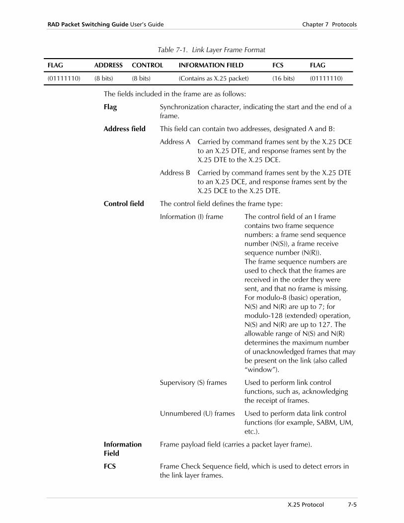
RAD Packet Switching Guide User’s Guide Chapter 7 Protocols
X.25 Protocol 7-5
Table 7-1. Link Layer Frame Format
FLAG ADDRESS CONTROL INFORMATION FIELD FCS FLAG
(01111110) (8 bits) (8 bits) (Contains as X.25 packet) (16 bits) (01111110)
The fields included in the frame are as follows:
Flag Synchronization character, indicating the start and the end of a frame.
Address field This field can contain two addresses, designated A and B:
Address A Carried by command frames sent by the X.25 DCE to an X.25 DTE, and response frames sent by the X.25 DTE to the X.25 DCE.
Address B Carried by command frames sent by the X.25 DTE to an X.25 DCE, and response frames sent by the X.25 DCE to the X.25 DTE.
Control field The control field defines the frame type:
Information (I) frame The control field of an I frame contains two frame sequence numbers: a frame send sequence number (N(S)), a frame receive sequence number (N(R)). The frame sequence numbers are used to check that the frames are received in the order they were sent, and that no frame is missing. For modulo-8 (basic) operation, N(S) and N(R) are up to 7; for modulo-128 (extended) operation, N(S) and N(R) are up to 127. The allowable range of N(S) and N(R) determines the maximum number of unacknowledged frames that may be present on the link (also called “window”).
Supervisory (S) frames Used to perform link control functions, such as, acknowledging the receipt of frames.
Unnumbered (U) frames Used to perform data link control functions (for example, SABM, UM, etc.).
Information Field
Frame payload field (carries a packet layer frame).
FCS Frame Check Sequence field, which is used to detect errors in the link layer frames.
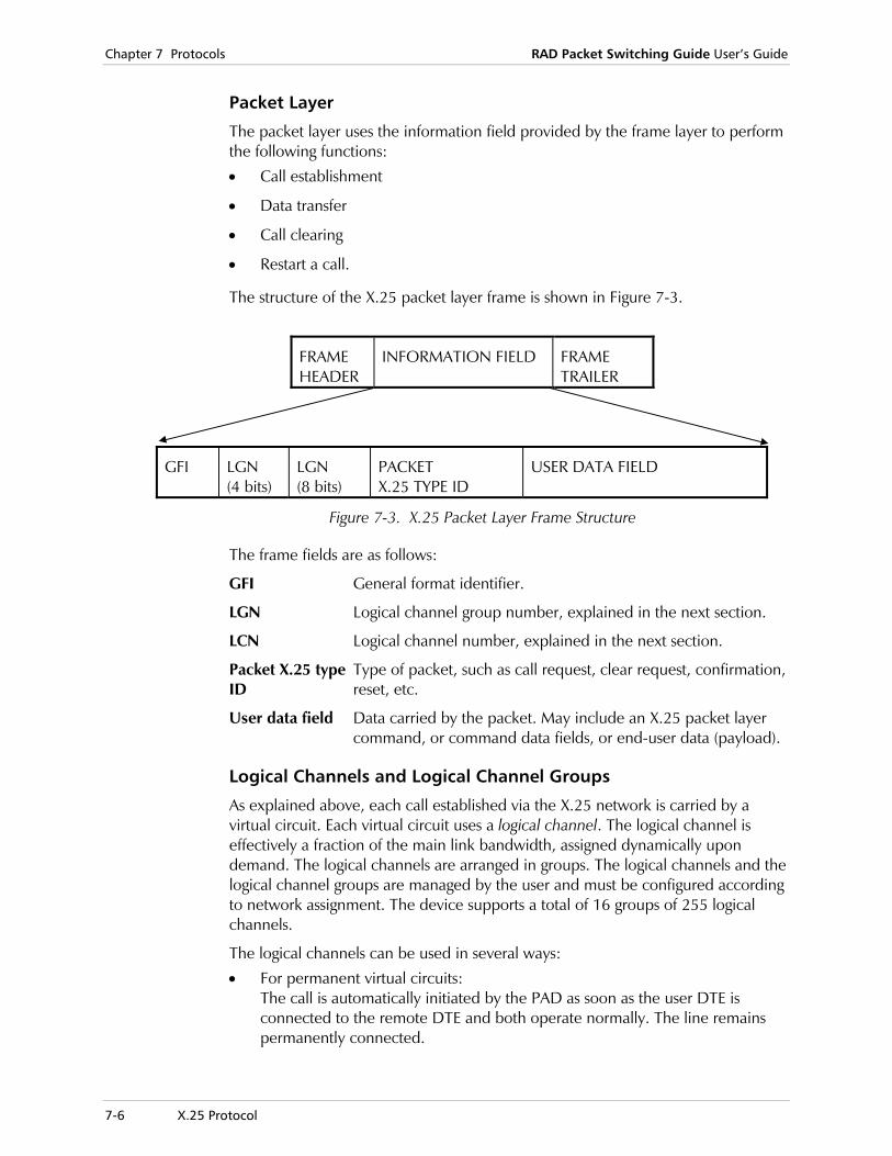
Chapter 7 Protocols RAD Packet Switching Guide User’s Guide
7-6 X.25 Protocol
Packet Layer
The packet layer uses the information field provided by the frame layer to perform the following functions:
• Call establishment
• Data transfer
• Call clearing
• Restart a call.
The structure of the X.25 packet layer frame is shown in Figure 7-3.
FRAME HEADER
INFORMATION FIELD FRAME TRAILER
GFI LGN (4 bits)
LGN (8 bits)
PACKET X.25 TYPE ID
USER DATA FIELD
Figure 7-3. X.25 Packet Layer Frame Structure
The frame fields are as follows:
GFI General format identifier.
LGN Logical channel group number, explained in the next section.
LCN Logical channel number, explained in the next section.
Packet X.25 type ID
Type of packet, such as call request, clear request, confirmation,reset, etc.
User data field Data carried by the packet. May include an X.25 packet layer command, or command data fields, or end-user data (payload).
Logical Channels and Logical Channel Groups
As explained above, each call established via the X.25 network is carried by a virtual circuit. Each virtual circuit uses a logical channel. The logical channel is effectively a fraction of the main link bandwidth, assigned dynamically upon demand. The logical channels are arranged in groups. The logical channels and the logical channel groups are managed by the user and must be configured according to network assignment. The device supports a total of 16 groups of 255 logical channels.
The logical channels can be used in several ways:
• For permanent virtual circuits: The call is automatically initiated by the PAD as soon as the user DTE is connected to the remote DTE and both operate normally. The line remains permanently connected.

RAD Packet Switching Guide User’s Guide Chapter 7 Protocols
X.25 Protocol 7-7
• For one-way incoming calls: The logical channel will accept only calls initiated by the remote DTE and will reject call requests initiated by the local DTE. After the call is set up, data can be interchanged in both directions.
• For one-way outgoing calls: The logical channel will accept only calls initiated by the local DTE and will reject call requests initiated by the remote DTE. After the call is set up, data can be interchanged in both directions.
• For two-way calls: The logical channel will accept and initiate calls.
Assignment of Logical Channels
To prevent the occurrence of collisions between requests for the assignment of logical channels received from the X.25 network and the requests received from the local DTE, the logical channels are assigned as shown in the following figure.
LOGICAL CHANNEL NUMBER (LCN)
RESERVED
PERMANENT VIRTUAL CIRCUITS
ONE WAY INCOMING
TWO WAY
ONE WAY OUTGOING
4095
SWITCHEDVIRTUALCIRCUITS
0
1
LOWEST INCOMING CHANNEL (LIC)
LOWEST TWO WAY CHANNEL (LTC)
LOWEST OUTGOING CHANNEL (LOC)
HIGHEST TWO WAY CHANNEL (HTC)
HIGHEST OUTGOING CHANNEL (HOC)
HIGHEST INCOMING CHANNEL (HIC)
Figure 7-4. Assignment of Logical Channels
As shown in the figure above, the logical channels are arranged in sets. The sets are assigned to specific uses:
• The lowest set, starting with logical channel 1, is assigned to permanent virtual circuits.
• To avoid frequent rearrangement of logical channels, not all logical channels within the range defined for permanent virtual circuits are necessarily assigned.
• Logical channels assigned to permanent virtual circuits must not be used for switched virtual circuits.
Notes

Chapter 7 Protocols RAD Packet Switching Guide User’s Guide
7-8 X.25 Protocol
• The next set, assigned to one-way incoming calls is defined by indicating its lowest (LIC) and highest (HIC) logical channel numbers.
• The next set, assigned to two-way incoming calls is defined by indicating its lowest (LTC) and highest (HTC) logical channel numbers.
• The next set, assigned to one-way outgoing calls is defined by indicating its lowest (LOC) and highest (HOC) logical channel numbers.
When some of these types of calls are not used, the next higher set starts on the lower boundary.
For example, in the absence of permanent virtual circuits, logical channel 1 is available for LIC. In the absence of permanent virtual circuits and one-way incoming logical channels, logical channel 1 is available for LTC. In the absence of permanent virtual circuits, one-way incoming logical channels and two-way logical channels, logical channel 1 is available for LOC.
Using these assignment conventions, an X.25 DCE that receives a call from the X.25 network will check the state of the logical channels included in the sets of one-way incoming and two-way logical channels, and will seize the lowest logical channel that is ready. For outgoing calls, the channel PAD of an X.25 DTE will search in the sets of two-way and one-way outgoing channels, and will seize the highest logical channel that is ready.

RAD Packet Switching Guide User’s Guide Chapter 7 Protocols
Frame Relay Protocol 7-9
7.2 Frame Relay Protocol
Introduction to Frame Relay Frame Relay is a new form of wide area networking, designed to maximize throughput and minimize costs by simplifying network processing. It is particularly suitable for applications in which the endpoints are intelligent devices (such as workstations, or LAN interconnect bridges) and where transmission lines are of high quality.
The Frame Relay network provides similar types of connectivity to the more traditional X.25 public networks, but by reducing the protocol processing at each network node, the overall throughput is increased. Whereas an X.25 network node must typically perform relatively complex functions of flow control and acknowledgments, a Frame Relay node performs almost no processing on the frames that pass through it. All acknowledgments and error recovery are performed end-to-end by the user’s terminals. Likewise, flow control is also done at the endpoints (though the network does generate indications of congestions when necessary). Frame Relay’s simplified network handling leads to more efficient line usage, increasing the data throughput of the network.
Currently, much of the high throughput data is sent over leased lines (when the capacity of X.25 is not sufficient). Again, Frame Relay offers some advantages, which are relevant in a large number of high performance applications.
First, a Frame Relay network provides far greater connectivity (and hence potentially cheaper connection costs) than a network of leased lines. Leased lines generally provide a connection between two distinct points, whereas Frame Relay is a true wide area network.
Second, many high performance applications do not require high throughput all the time. For example, graphic programs, which often involve human interaction at some point, are inherently “bursty” by nature. On a leased line, you pay for the entire bandwidth regardless of the amount of actual data that is transmitted. During bursts, the bandwidth is being used, but during idle periods, it is wasted. A Frame Relay, in contrast, multiplexes statistically the several user frames over the line and can be configured to accommodate bursts of data from each individual user periodically. For constantly high bandwidth applications, leased lines will continue to provide a better solution, but for bursty applications, Frame Relay is often preferable.
There are two basic conditions that should exist in order for Frame Relay to be justifiable. The first is that the quality of the transmission lines must be good. Frame Relay will only function efficiently if the error rate of the underlying physical medium is low.

Chapter 7 Protocols RAD Packet Switching Guide User’s Guide
7-10 Frame Relay Protocol
The second condition is that the nodes connecting to the Frame Relay are not dumb terminals, but will run their own protocols for flow control, error recovery and acknowledgments. This is true for nearly all workstations, X.25 terminals or devices, routers and gateways connecting LANs to public telecommunications networks. When the device is acting as a Frame Relay end user device, this condition is met by arranging the data from the end users in X.25 packets and encapsulating these packets over the Frame Relay link.
Frame Relay Standards
ANSI standards T1.606 and T1.618 define the Frame Relay core procedures: these are the procedures used to handle users data frames at a Frame Relay network node (or user nodes performing Frame Relay encapsulation). ANSI standard T1.617 defines maintenance procedures for Frame Relay networks. These specify types of messages exchanged between a user terminal and the node through which it connects to the network. Of particular relevance is Annex D to this standard, which defines procedures applicable to permanent virtual circuits (PVCs).
Prior to ANSI standard T1.617 Annex D, a consortium of companies defined a mechanism for Frame Relay PVC management, called LMI (Link Management Interface). The LMI defines a functionality similar to that defined (later) by ANSI standard and is currently a widely supported standard in existing Frame Relay networks.
Frame Relay Nodes
There are three different classes of nodes within the Frame Relay network:
• End user nodes
• Network access nodes
• Internal network nodes 0.
USERNODES
NETWORKACCESSNODES
INTERNALNETWORK
NODES
Figure 7-5. Types of Nodes

RAD Packet Switching Guide User’s Guide Chapter 7 Protocols
Frame Relay Protocol 7-11
User nodes are the only terminals in the network that handle the application data. They communicate directly with network access nodes: these are the nodes through which the frame relay network is accessed by the user terminals. Finally, the Frame Relay network itself consists of (internal) network nodes.
Functionally, the network access nodes and internal network nodes are similar, performing switching on all data frames they receive. Yet, they are not identical; two main differences exist. First, the network access nodes perform the network side of the maintenance procedures (ANSI T1.617 or LMI). These procedures do not involve internal network nodes. The second difference involves the checking of user’s bandwidth consumption (discussed below). This is usually done in the network access nodes (although it could be done in any node in the network if desired).
The three different classes of nodes are illustrated in the figure above. The encircled area is the logical boundary of the Frame Relay network.
Frame Relay Protocol Frame relay protocol is based on the core aspects of LAPD (Link Access Protocol D), the link layer protocol specified by ITU. Frame relay uses the LAPD frame to enclose both user data and the address information used to route the frame (see the following figure). The address information is known as the Data Link Connection Identifier (DLCI). The Frame Relay header, which is a two-byte field within the frame, is specified for enclosing a DLCI representing the destination of the frame. A Frame Check Sequence (FCS) is utilized between the access device and the network to ensure bit integrity of the frame. Frames with errors are discarded. Unlike X.25 networks, protocols in the endpoint devices must recognize the dropped frames and recover by reinitiating transmission.
FLAGFRAME RELAYHEADER
FRAME CHECKSEQUENCE
VARIABLE LENGTH
FLAG
1 BYTE 2 BYTES 2 BYTES 1 BYTE
EXAMINED BY FRAMERELAY SWITCH
INFORMATION EXAMINED BY FRAMERELAY SWITCH
TCP/IP OR OTHER LAN PROTOCOL
X.25 PACKET
HDLC/SDLC FRAME
Figure 7-6. Frame Relay Frame Format
The information field (I-field) of the FR frame is of variable length. The theoretical maximum is 4096 bytes corresponding to FCS limits. The I-field contains the user data that are passed between devices over a frame relay network. The user data may contain various types of protocols (PDUs or Protocol Data Units) utilized by the access dividers. Protocol information sent in the information field is transparent to the frame relay network.
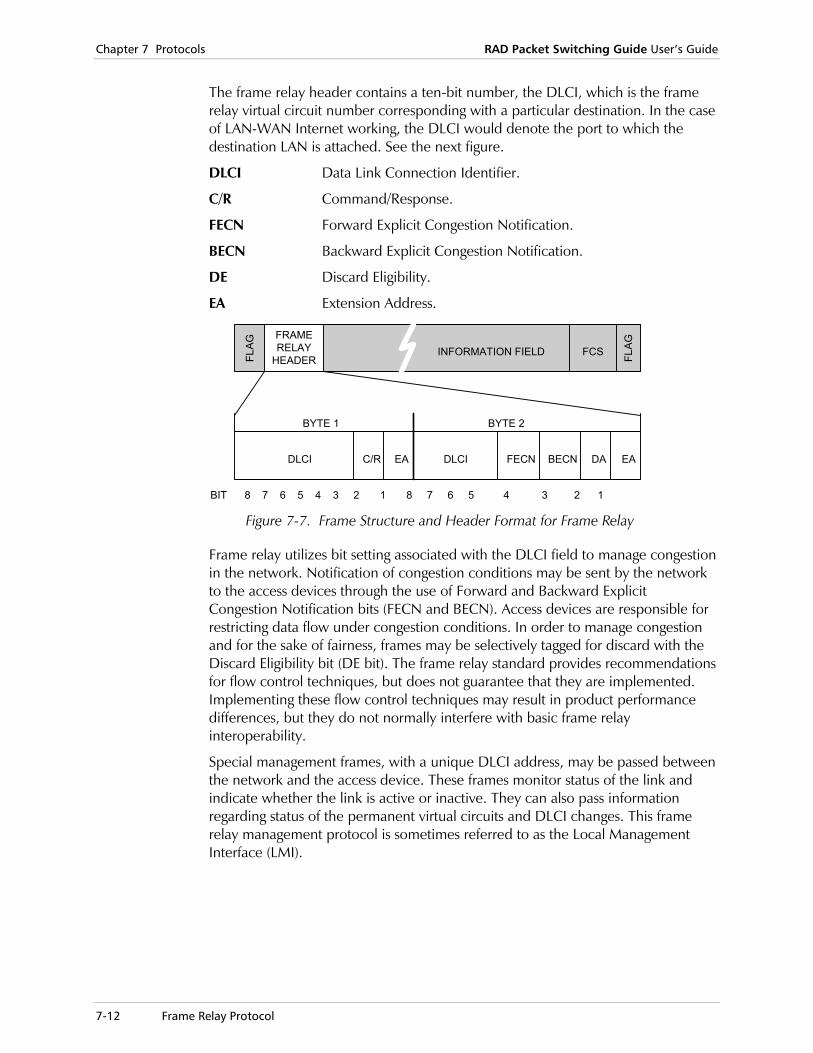
Chapter 7 Protocols RAD Packet Switching Guide User’s Guide
7-12 Frame Relay Protocol
The frame relay header contains a ten-bit number, the DLCI, which is the frame relay virtual circuit number corresponding with a particular destination. In the case of LAN-WAN Internet working, the DLCI would denote the port to which the destination LAN is attached. See the next figure.
DLCI Data Link Connection Identifier.
C/R Command/Response.
FECN Forward Explicit Congestion Notification.
BECN Backward Explicit Congestion Notification.
DE Discard Eligibility.
EA Extension Address.
FRAMERELAY
HEADERFLAG
FLAGFCS
BECNFECNDLCI EADAEAC/RDLCI
BIT 8 7 6 5 4 3 2 1 8 7 6 5 4 3 2 1
BYTE 1 BYTE 2
INFORMATION FIELD
Figure 7-7. Frame Structure and Header Format for Frame Relay
Frame relay utilizes bit setting associated with the DLCI field to manage congestion in the network. Notification of congestion conditions may be sent by the network to the access devices through the use of Forward and Backward Explicit Congestion Notification bits (FECN and BECN). Access devices are responsible for restricting data flow under congestion conditions. In order to manage congestion and for the sake of fairness, frames may be selectively tagged for discard with the Discard Eligibility bit (DE bit). The frame relay standard provides recommendations for flow control techniques, but does not guarantee that they are implemented. Implementing these flow control techniques may result in product performance differences, but they do not normally interfere with basic frame relay interoperability.
Special management frames, with a unique DLCI address, may be passed between the network and the access device. These frames monitor status of the link and indicate whether the link is active or inactive. They can also pass information regarding status of the permanent virtual circuits and DLCI changes. This frame relay management protocol is sometimes referred to as the Local Management Interface (LMI).
RAD Packet Switching Guide User’s Guide Chapter 7 Protocols
Frame Relay Protocol 7-13
Congestion The preceding sections outline the simplicity of the Frame Relay architecture. However, since it lacks any rich protocol, the network nodes are now prone to congestion to a greater degree than with alternative architectures. Congestion (which stems from lack of resources) can cause frame loss, which will usually result in polling requests and re-transmissions to be sent by the user's terminals. This causes obvious, and sometimes severe, performance degradation. Sustained congestion will eventually cause user applications connected to the Frame Relay network to collapse. Ideally, the network should allocate enough resources to prevent congestion from ever occurring.
The solution provided is for the network to send indications to the user devices whenever it approaches what it defines to be congestion. These indications (which are bits within the DLCI field of the frames) are expected to be examined by the user device and cause it to reduce the amount of data being transmitted across the network. In the device it is accomplished by the funnel system - when a funnel receives an indication of congestion from the network, it decreases its gauge rate, thereby reducing the amount of data being transmitted to the network. Note that each node handles frames in two directions (receive and transmit). It is quite possible that a node may be congested in only one of these directions. Two bits are used for explicit congestion notification: one is set on all frames passing through that node forward along the path (FECN: Forward Explicit Congestion Notification) and the other is set on all frames that pass through that node in the opposite direction (BECN: Backward Explicit Congestion Notification). This effectively shifts the onus of congestion to the user devices. Other (additional) methods of congestion notification are suggested by the various management protocols.
The only other mechanism available to the Frame Relay network is the DE (Discard Eligibility) bit. Any frame received with the DE bit set (it is also within the DLCI field) can be discarded by the network. The DE bit can be used by user applications on non-critical frames, or by the network access nodes if the attached user is using “too much” of the bandwidth available on its line.
Committed Information Rate (CIR)
The idea that a user can be consuming “too much” bandwidth was introduced in the previous paragraph. Bandwidth is usually defined at the Frame Relay network access points - the points at which the user connects to the Frame Relay network. Each user is allocated a rate (in terms of bits per second) at which he commits to transmit his data (i.e., the transfer rate should not exceed this number). Optionally, an additional (excess) data rate may be specified if the first (lower) rate is exceeded during bursts. When these transfer rates are exceeded, the Frame Relay access node is entitled to take steps in order to “punish” the offenders - either by setting the DE bit in that user’s frames or, in more extreme cases, by discarding all frames sent by that user. In this context, a user corresponds to a single DLCI value.

Chapter 7 Protocols RAD Packet Switching Guide User’s Guide
7-14 Frame Relay Protocol
Funnels Funnels are objects that have been defined for use at user terminals. The purpose of the funnel is to provide the user with greater control over the applications connecting to the Frame Relay.
A user terminal (in the context of Frame Relay network) can be a type of router that may be transmitting different protocols for very different types of applications over the Frame Relay network. Examples of these are LAN interconnects and multi-protocol routers. In these cases, the Frame Relay network terminates at the router, but the “real” user application is situated somewhere across a LAN (or some other type of network).
Users of this kind face two types of problems in configuring their Frame Relay connections.
The first problem relates to congestion avoidance and recovery. We have seen that the user will receive indications of congestion from the network for some port. Over this port there may be several different applications currently transmitting data. How does the router compel each of the applications (which may be implementing very different protocols) to slow down its transmission rates? Ideally, we should search for a solution where a) we do not need to tamper with the exiting user applications (since these are not with the router anyway) and b) we can handle all different types of applications in a uniform manner. Both of these goals can be achieved by using funnels.
The second problem relates to the need some applications will have for controlling their actual bandwidth consumption rates. Many Frame Relay networks allow applications to transmit at a committed information rate: when a DLCI exceeds this rate, the DE-bit is set on all frames transmitted by it. If the excess burst rate is also used up, frames are discarded until the transmission rate drops.
It may be desirable for our router to be configured to control the transmission rates of its DLCIs in accordance with the type of application associated with each DLCI. Some applications may be very sensitive to frame loss and will want to avoid exceeding their committed information rate at all costs; others will want to maximize data throughput to the utmost. By using funnels, the router can configure each DLCI in a way that is optimal for its type of application.
Funnels are attached to DLCIs: all data transmitted by a DLCI are poured through its funnel. The funnel is defined by an output rate (called its gauge) and a depth. As long as the transmission rate of a DLCI is within its funnel's gauge, the funnel has no effect. However, if the DLCI generates data faster than the funnel's gauge, the excess data are stored with the funnel. As this continues, more and more data will pile up within the funnel. When this reaches a pre-defined high-water level, the funnel will automatically widen its gauge, immediately transmitting the excess data.
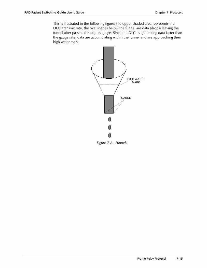
RAD Packet Switching Guide User’s Guide Chapter 7 Protocols
Frame Relay Protocol 7-15
This is illustrated in the following figure: the upper shaded area represents the DLCI transmit rate, the oval shapes below the funnel are data (drops) leaving the funnel after passing through its gauge. Since the DLCI is generating data faster than the gauge rate, data are accumulating within the funnel and are approaching their high water mark.
HIGH WATERMARK
GAUGE
Figure 7-8. Funnels

Chapter 7 Protocols RAD Packet Switching Guide User’s Guide
7-16 HDLC Protocol
7.3 HDLC Protocol
A substantial improvement over Async and bisync is the ISOs High-Level Data Link Control (HDLC). This protocol is based largely on the pioneering work done by IBM on its replacement for BSC, the Synchronous Data Link Control (SDLC) protocol. SDLC and HDLC represent a significant departure from their forerunners because they are bit-oriented rather than character-oriented. (Other contemporary bit-oriented protocols, such as ANSI’s Advanced Data Communications Control Procedure and Burrough’s Data Link Control are closely related to HDLC.)
In a bit-oriented protocol, the frame length can be an arbitrary number of bits, rather than a fixed multiple of any selected character size. A further advantage in using a bit-oriented protocol is a reduction in the number of framing and control characters needed, since each bit in an 8-bit character may be used independently to achieve control significance.
All HDLC frames conform to the frame structure shown in the next figure. Each begins and ends with a Flag pattern: a bit sequence consisting of a binary zero, followed by six ones and another zero. These 01111110 markers are used as reference points to provide frame synchronization. When a line is quiet or idle, these flags are sent continuously for interframe time fill and to maintain synchronization between sender and receiver.
ADDRESSFIELD
INFORMATIONFIELD
CONTROLFIELD
FRAME CHECKSEQUENCE
FLAG FLAG
01111110 01111110
8 BITS 8 BITS 8 BITS N BITS 16 BITS 8 BITS Figure 7-9. HDLC Frame Structure
To be valid, a frame must have a least 32 bits between its flags. Frames that are invalid are disregarded. For the sake of economy, a single flag may be used to identify the end of one frame and the beginning of another.
When a receiver detects a flag, it examines the data stream for an 8-bit address field. The term “address” can be particularly misleading when discussing X.25. This is not the DTE’s network address; it originates within HDLC (and SDLC). These protocols can be used on multipoint lines, supporting as many as 256 terminal control units or secondary stations per line. Therefore, in a multipoint circuit, this address field is used to poll control units.
The control field identifies the frame type and is used to carry frame sequence numbers, frame acknowledgments, retransmission requests, and other control information.
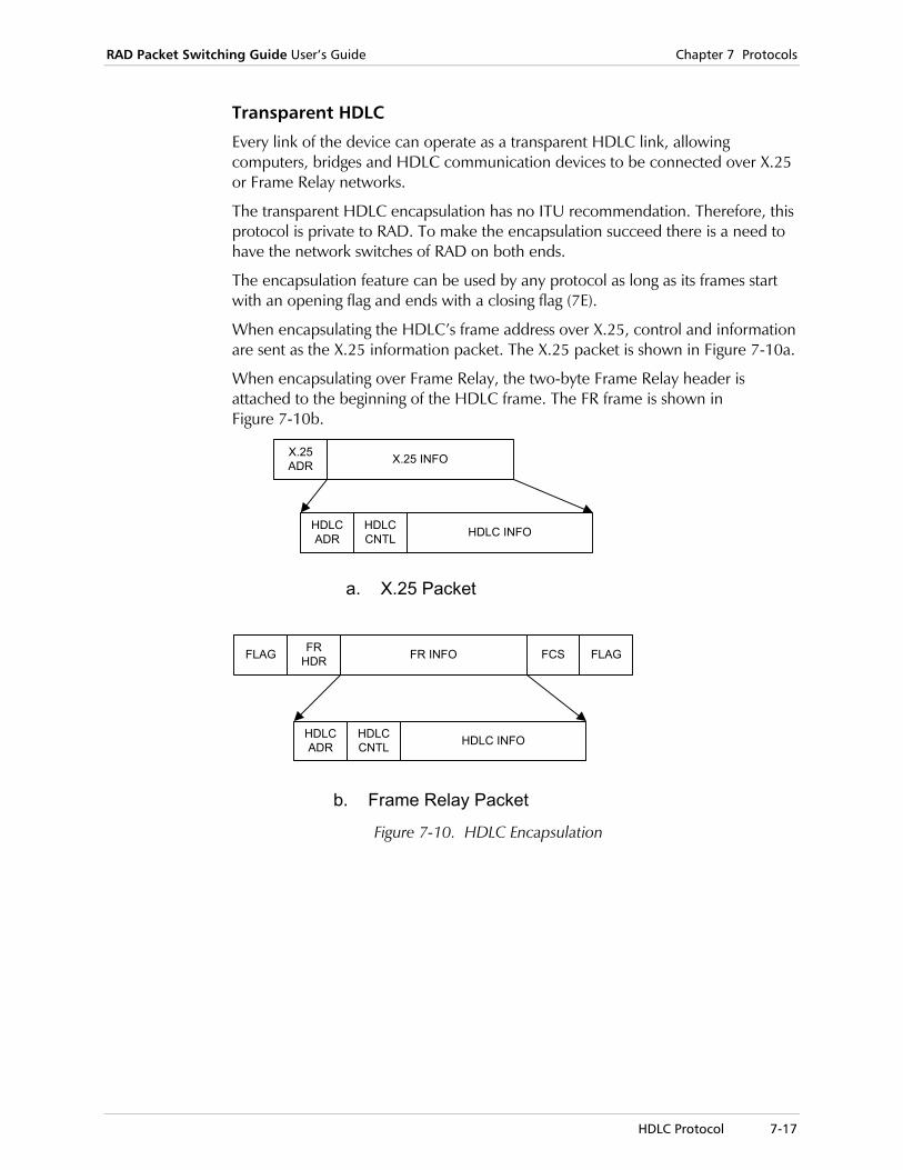
RAD Packet Switching Guide User’s Guide Chapter 7 Protocols
HDLC Protocol 7-17
Transparent HDLC
Every link of the device can operate as a transparent HDLC link, allowing computers, bridges and HDLC communication devices to be connected over X.25 or Frame Relay networks.
The transparent HDLC encapsulation has no ITU recommendation. Therefore, this protocol is private to RAD. To make the encapsulation succeed there is a need to have the network switches of RAD on both ends.
The encapsulation feature can be used by any protocol as long as its frames start with an opening flag and ends with a closing flag (7E).
When encapsulating the HDLC’s frame address over X.25, control and information are sent as the X.25 information packet. The X.25 packet is shown in Figure 7-10a.
When encapsulating over Frame Relay, the two-byte Frame Relay header is attached to the beginning of the HDLC frame. The FR frame is shown in Figure 7-10b.
X.25ADR X.25 INFO
HDLCADR HDLC INFOHDLC
CNTL
FR INFOFLAG FRHDR FCS FLAG
HDLCADR HDLC INFOHDLC
CNTL
a. X.25 Packet
b. Frame Relay Packet Figure 7-10. HDLC Encapsulation

Chapter 7 Protocols RAD Packet Switching Guide User’s Guide
7-18 STM Protocol
7.4 STM Protocol
STM Links in the APS/SPS General The STM protocol enables to expand the number of Async channels for PAD/FRAD. The STM protocol is a proprietary protocol used in RAD statistical multiplexers (STM-4, STM-8, STM-16 and STM-24). The APS/SPS may be configured to link with a RAD STM via any of its sync links to form a multichannel PAD.
The STM channels may be used as PAD channels. They may be configured as a PAD channel via the channel configuration menu.
The STM Async Channels are numbered according to the link number:
• For link number 1, in STM-8 they are numbered 101-108.
• For link number 1, in STM-24 they are numbered 101-124.
• For link number 2, in STM-8 they are numbered 201-208.
• For link number 2, in STM-24 they are numbered 201-224.
• For link number 12, in STM-8 they are numbered 1201-1208.
• For link number 12, in STM-24 they are numbered 1201-1224.

RAD Packet Switching Guide User’s Guide Chapter 7 Protocols
MPE Protocol 7-19
7.5 MPE Protocol
The Multiple Point Encapsulation protocol (MPE) is a proprietary RAD protocol. It is designated to enable a generic HDLC device multiple encapsulation over X.25 and Frame Relay protocols. The MPE may also be used as a multiplexer of local HDLC connections onto one physical link.
The RAD MPE protocol enables simple end user devices the ability of accessing a complex protocol network. While these end user devices would originally not be complex enough to support X.25 or Frame Relay protocols the MPE packets are easy to create. This “easy to create” data packet will then be forwarded to the RAD switch, which will encapsulate it over the desired protocol and forward it onwards.
The MPE protocol does not support link control facilities. Especially, it has no formal synchronization mechanism and therefore no synchronization indication can be given.
MPE Protocol Frame Structure The following figure displays a basic MPE frame.
OFFSET AID Data (Up to 8K)
Figure 7-11. Basic MPE Frame Structure
The MPE packet consists of three fields:
OFFSET A one byte long field, determining the offset of valid data from the beginning of the frame.
AID Address ID of the packet. It is used to determine:
Specific logical link across the physical port. This AID feature is similar to the Frame Relay protocols DLCI (Data Link Connection Identifier)
Session in which the HDLC device uses to forward data (X.25, SVC, PVC, FR, etc.).
DATA A data field up to 8K bytes long.
The MPE link configuration requires the configuration of two sets of parameters:
• AID configuration: The AID set of parameters define the logical link across the physical port and identify the session onto which the MPE protocol is encapsulated.
• PORT configuration: The second set of parameters, the PORT configuration of the MPE link. This set of parameters relate directly to the MPE PORT attributes. These

Chapter 7 Protocols RAD Packet Switching Guide User’s Guide
7-20 MPE Protocol
parameters specifically define the inactivity support, X.25 facilities, Local Subaddresses, Flow control parameters and Internal Clock.

RAD Packet Switching Guide User’s Guide Chapter 7 Protocols
ISDN 7-21
7.6 ISDN
The RAD packet switching devices software versions 4.0 and higher support ISDN protocol. ISDN interface (MOBI) is incorporated into the packet switching devices.
The ISDN interface is a dialed connection to an ISDN network. An ISDN physical link multiplexes two B-channels, where each B-channel is a separate dialed call. When the ISDN interface is installed on a packet switching device, each of the B-channels can be directed to a different link, thus making it possible to establish two physical connections to an ISDN address.
The ISDN function will operate under X.25 and Frame Relay protocols. Applications running over these protocols (including IP), may be applied as well. This enables running the application traffic over ISDN lines.
ISDN Algorithm for Initiating a Call On an X.25 link, the trigger for initiating an ISDN call is an X.25 call request. The link that issues the call request is automatically selected from a pool of all ISDN links that are preconfigured as X.25.
On a Frame Relay link, the link management (maintenance protocol) will be removed so that the link will be UP. Upon reception of data, a call is initiated and the management becomes operational.
A retry mechanism (counter + timer) is used for the case of ISDN call rejection.
ISDN Algorithm for Receiving a Call An incoming ISDN call has to be identified for two reasons.
1. To direct it to one of the two links (which are connected to the ISDN interface).
2. In order to provide security.
Incoming call routing and security are provided with the Accept-list mechanism. The Accept-list is a list of entries that hold information on ISDN calling addresses from which it is allowed to receive a call.
X.25 Over ISDN
An ISDN call will be cleared (hang-up) after inactivity timer expiration. The inactivity timer will start when there is no open X.25 call.
An ISDN-call clear does not clear X.25 calls on that link. X.25 calls will be cleared when the link looses sync.

Chapter 7 Protocols RAD Packet Switching Guide User’s Guide
7-22 ISDN
Frame Relay over ISDN Each port with an ISDN physical layer will be temporarily set without management (maintenance protocol) so that the link and all DLCI’s on this port will be up. This enables the device to route data to the link, which initiates an ISDN call because ISDN is usually used as backup.
The temporary non-management setting occurs approximately 60 seconds after the device is turned on. The delay enables the synchronization of the non-ISDN Frame Relay links prior to the ISDN link. This prevents any unnecessary ISDN calls as the data is first routed to the main non-ISDN Frame Relay link.
When there is no activity on the port (there is no data received or transmitted), the call should be cleared after inactivity timer expiration.
Frame Relay: Outgoing ISDN Call
When there is data on this port, the specific DLCI will be fetched. According to the DLCI’s configuration, an ISDN address will be selected, and an attempt to open an ISDN call will be made.
After the call opens, the port will be reconfigured with management.
When the call is cleared, the port will be reconfigured without Management.
If all retries are rejected, the old frames on the driver will be cleared.
Frame Relay: Incoming ISDN Call
Incoming calls will be connected according to the accept-list mechanism.
When an ISDN call is accepted, the management of the Frame Relay port is automatically set on.
X.25 over Frame Relay over ISDN In the case of X.25 over frame relay a combination of the above FR encapsulations is used. The trigger for initiating a call is an X.25 call request. The X.25 routing is used to direct a call to a specific port and DLCI.

RAD Packet Switching Guide User’s Guide Chapter 7 Protocols
SNA 7-23
7.7 SNA
The primary function of the RAD Packet Switching devices SNA support is to provide a communications interface to X.25 and Frame Relay networks for IBM terminals and computers. As part of it’s primary function, the devices SNA support performs protocol conversion between the SNA protocols: LLC2 over Frame relay; QLLC over X.25 and SDLC over synchronous links.
The main features of the SPS SNA/SDLC PAD functionality are:
• Handling of the following SNA Protocols: SDLC, QLLC/X.25, QLLC/X.25 over Frame Relay, LLC2/RFC1490 over Frame Relay; Primary and Secondary variants of all protocols.
• Support for a single DLCI carrying both SNA/RFC-1490 Data Traffic for local handling by SPS and SNA/RFC-1490 traffic to be switched by the SPS.
• Protocol Spoofing. All protocols are locally terminated. No end-to-end polls traverse the Frame relay or X.25 network.
• RAD Any-to-Any support features plug-and-play protocol conversion between any combination of the supported SNA protocols.
• Complete statistics and monitoring of operational state at PU and Link level for SDLC, QLLC, LLC2, Frame Relay and X.25 links.
• Support for PU-1, Local XID Processing, End to End XID Processing (Negotiable, Primary and Secondary) including the following partial list: NCP/NPSI/X.25, NCP/SDLC, 5250, 3174, 3274, 3276, S/36, S/38, AS400, OS/2-CM(SDLC) and Peer-to-Peer Nodes (APPN) running IBM APPC.
• Support for XID3, allowing End-to-End XID Processing to establish a logical link through the SPS, including dynamic link role negotiation.
• Addition of multi-host capabilities to an SNA network.
• Full support for Non-Activation XID3 transfers.
• TPAD, HPAD configurable on a per link basis provides flexibility.
• Local XID Processing and End-to-End XID Processing can coexist on a common SPS SDLC link.
• RAD’s SNA support can replace NPSI transparently to all applications supporting QLLC.
• Enhanced Group Polling.
• Flexible Routing based on Subaddress or call user data field.
• Security password protection and callback facility.
• Maximum BTU length 5120 bytes.
• Facilities and Call User Data on a per individual PU.
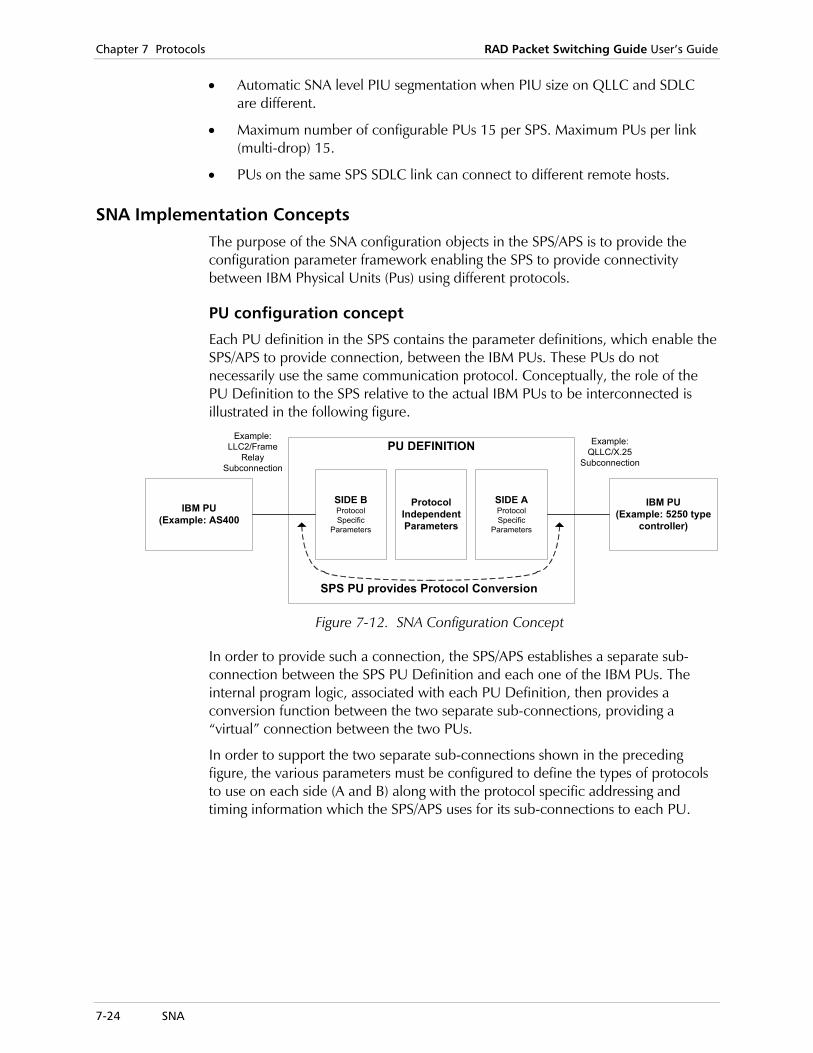
Chapter 7 Protocols RAD Packet Switching Guide User’s Guide
7-24 SNA
• Automatic SNA level PIU segmentation when PIU size on QLLC and SDLC are different.
• Maximum number of configurable PUs 15 per SPS. Maximum PUs per link (multi-drop) 15.
• PUs on the same SPS SDLC link can connect to different remote hosts.
SNA Implementation Concepts The purpose of the SNA configuration objects in the SPS/APS is to provide the configuration parameter framework enabling the SPS to provide connectivity between IBM Physical Units (Pus) using different protocols.
PU configuration concept
Each PU definition in the SPS contains the parameter definitions, which enable the SPS/APS to provide connection, between the IBM PUs. These PUs do not necessarily use the same communication protocol. Conceptually, the role of the PU Definition to the SPS relative to the actual IBM PUs to be interconnected is illustrated in the following figure.
IBM PU(Example: AS400
IBM PU(Example: 5250 type
controller)
SIDE AProtocolSpecific
Parameters
SIDE BProtocolSpecific
Parameters
ProtocolIndependentParameters
SPS PU provides Protocol Conversion
Example:LLC2/Frame
RelaySubconnection
Example:QLLC/X.25
Subconnection
PU DEFINITION
Figure 7-12. SNA Configuration Concept
In order to provide such a connection, the SPS/APS establishes a separate sub-connection between the SPS PU Definition and each one of the IBM PUs. The internal program logic, associated with each PU Definition, then provides a conversion function between the two separate sub-connections, providing a “virtual” connection between the two PUs.
In order to support the two separate sub-connections shown in the preceding figure, the various parameters must be configured to define the types of protocols to use on each side (A and B) along with the protocol specific addressing and timing information which the SPS/APS uses for its sub-connections to each PU.
RAD Packet Switching Guide User’s Guide Chapter 7 Protocols
SNA 7-25
SNA PU Protocol Implementation
In the process of facilitation an end-to-end connection between a pair of Peer PUs, the SPS supports a separate local connection between itself and each one of the PUs. The SPS then performs the internal function of protocol conversion, which ‘grafts’ the two separate local connections into a single virtual end-to-end connection between these peer PUs (with the SPS acting as a transparent intermediary).
As part of this process, the SPS supports various protocols in its local connections to the PUs. The SPS supports synchronous SDLC, LLC2-Frame Relay and QLLC-X25. In each case, the SPS can perform the Primary or Secondary role of the protocols, for attachment to terminal or host equipment, respectively. The SPS is capable of providing a virtual connection between any pair of these protocols.
Protocol Spoofing or local termination is the process performed by the SPS, whereby all protocol polling, response and control frames are limited to data traffic within the local sessions between the SPS and each peer PU. The SPS passes only pure data aver the WAN to the partner peer PU. The SPS implements protocol spoofing for SDLC, LLC2 and QLLC, both primary and secondary modes.
Global SNA Parameters
The Global SNA parameters define the characteristics that are common to the entire SNA sub-system, including all PU definitions, SNA protocols SDLC links. The following parameters are configured:
Frame Relay LLC Source MAC Address
Source MAC address of the SPS, used for all connections of PUs over Frame Relay or Ethernet.
Default Frame Relay port
Default destination Frame Relay port that the device sends the frame to when the frame is accepted by the LLC2 link, but its addressing does not correspond to any of the configured LLC2.
Default Frame Relay DLCI
Used when SPS receives LLC2 over Frame Relay data traffic only. This parameter is applicable when the SPS receives LLC2 over Frame Relay data traffic only. This parameter defines the default destination DLCI for the defined Default Frame Relay port.
Chapter 7 Protocols RAD Packet Switching Guide User’s Guide
7-26 SNA
SNA X.25 Implementation on the SPS
X.25 Routing of SNA Protocols within the SPS
The following is the revised routing algorithm used by the SPS, which takes into consideration the PU subaddressing capability.
IF PID == 0xC3 or 0xCB then
| SDLC PAD does the following routing procedure:
| IF User Data Field of Call Indication contains QXID then
| | IF IDNUM/IDBLK in User Data Field == IDNUM/IDBLK in any PU definition
| | | Route the call to that matching PU definition.
| | OTHERWISE, reject the incoming Call Indication.
| OTHERWISE
| IF X.25 Subaddress is present in incoming call packet
| | IF X.25 subaddress == Subaddress in any non-connected PU Definition
| | | Route the call to that matching PU definition.
| | OTHERWISE, reject the incoming Call Indication.
| OTHERWISE
| IF there is any non-connected PU definition available
| | Route the call to that PU Definition
| OTHERWISE, reject the incoming Call Indication
|
OTHERWISE the SPS routes the call according to its central routing table
Call User Data and Facilities
This feature is supported for End-to-End XID Processing and Local XID Processing.
The default value is blank, No negotiation (00) and No Call User Data.
This parameter is applicable for outgoing calls only and is used with the X.25 called address and X.25 autocall parameters. When the SPS/APS PU sends a request for call, it can include Facilities and Call User Data in the request. The Call User Data is encoded in hexadecimal, in order to enable the inclusion of non-printable characters. This parameter can be up to 30 bytes long (60 hexadecimal digits). Each pair of digits represents one bytes in the manner shown below:
Digit number 0 1 2 3 4 5 58 59 max. 60 digits Byte number 0 1 2.......................29 max. 30 bytes
Byte 0 (digits 0 and 1) is reserved for X.25 Facilities. The remaining bytes define the Call User Data, as it will appear in the call request packet.
For more detailed configuration instructions and examples of the Call User Data and Facilities, see SNA in Chapter 2.

RAD Packet Switching Guide User’s Guide Chapter 7 Protocols
SNA 7-27
APPN/End to End XID Processing Implementation in the SPS
Backward Compatibility to Existing Local XID Processing Functionality
Each PU definition on the SPS can be configured as End-to-End XID Processing or Local XID Processing, where Local XID Processing configuration represents the previously existing SPS functionality. Both Local XID Processing and End-to-End XID Processing devices can be simultaneously attached to the same SPS SDLC link in a multi-dropped configuration. However, all devices attached to the same SDLC link, must implement the same SDLC role. Devices configured as Local XID Processing cannot engage in End to End XID Processing sessions and devices configured as End to End XID Processing cannot engage in Local XID Processing sessions.
Use of the SDLC address
SDLC Transmission using Broadcast Address hex FF
The SPS sends XID with SDLC address of hex FF in two cases:
• If the parameter “More than 1 PU participate on this link == N” and the SPS is implementing the SDLC Primary Link Station role
• If the SPS is passing a negotiable XID (also only allowed when parameter “More than 1 PU participate on this link == N”).
The SPS can discover the SDLC address of an adjacent Secondary station, when that secondary station is the sole device on the link (SDLC point-to-point).
Discovery of Adjacent Link Station SDLC Address
If parameter “More than 1 PU participate on this link == N,” the SPS will configure itself to use whatever SDLC address is received in response to its sending XID with address hex FF. In this case, any predefined SDLC address in the device configuration is disregarded and instead, the dynamically discovered SDLC address is used for the duration of the session.
SDLC Reception of Broadcast Address hex FF
The SPS will respond to the broadcast address using the address of the single device configured on that SPS SDLC line. Note that according to SDLC architectural rules, the broadcast address is allowed on point-to-point lines only. Therefore such a line when used with the SPS would have to be configured with parameter “More than 1 PU participate on this link == N”.
Establishing the Link Role
After power-up or reset, NOVRAM user configuration in the general PU configuration determines whether the SPS performs the Primary or Secondary link role for a given PU connection. The SPS then monitors all received XID traffic on a per PU basis, and adjusts the SPS link role accordingly.
Chapter 7 Protocols RAD Packet Switching Guide User’s Guide
7-28 SNA
SDLC Link Considerations
On a point-to-point SDLC link, the link role of the SPS can change one or more times between connections without having to reset the SPS. On a multi-point link, the link role becomes fixed after the first device successfully connects, and cannot be changed without system reset.
Default SDLC Link Role
The Default Link Role effects how the SPS makes use of and responds to the SDLC broadcast address, and whether it will perform initial XID polling or expect to be polled. The Default Link Role is defined on a per link basis, i.e. all PUs on the same link assume the same link role. The definition of "Default Link Role" is: that of the link role which the SPS assumes, when it is in-between connections. The power-up or reset Default Link Role of the SPS is determined according to the link role configured in the SDLC line configuration. On point-to-point links, upon establishment of each new connection, the SPS updates its default Link Role, with the link role of the newly established connection. On multi-point links, this updating of the Default Link Role occurs upon the first successful connection of a device. NULL XID due to the XID initiation parameter are always transmitted by the SPS unconditional of Link Role.
Link Role Negotiation
End to End XID Processing allows for communicating PUs to simply announce to each other their static link roles, or alternatively to dynamically negotiate their roles. The SPS supports both of these methods. Dynamic negotiation on multi-point SDLC links is not allowed according to the End to End XID Processing architecture. Therefor, if during operation of the SPS,an attempt is made to pass a negotiation XID over one of its SDLC links for which more than one PU is defined, the SPS takes the following action: the negotiation XID is transformed into a fixed XID using a static link role according to the Default Link Role for that SPS link.

RAD Packet Switching Guide User’s Guide Chapter 7 Protocols
SNA 7-29
Attachment of the SPS SDLC link to a Modem Sharing Device
SPS PU Link Role=Secondary: SPS connected on a tributary link, in parallel with other PUs
The SPS must be configured on its SDLC Line Configuration, with parameter Physical Mode set to Idles between flags. Parameter Link participates with more than one PU should be set to Yes.
Host
PU Device-A
PU Device-B
SPS HPAD
ModemSharingDevice
SDLC
Figure 7-13. HPAD Connected on a Tributary Link
In certain configurations, the Modem sharing device appears as a DTE which supplies clock on pin-24 of its interface. In this case, the SPS must be set up physically as a DTE, and be connected to the modem-sharing device using a cable with pin out as follows:
Figure 7-14. Modem Sharing Device Pin Out
Chapter 7 Protocols RAD Packet Switching Guide User’s Guide
7-30 Ethernet
7.8 Ethernet
Introduction to Ethernet The RAD Packet Switching devices provide connection to Ethernet networks. The Ethernet system is comprised of the following basic elements:
• The Physical Medium
• Access Control
• The Ethernet frame.
Physical Medium
The physical medium refers to the medium used for sending the Ethernet signals between computers on the network. Ethernet is a 10-Mbps broadcast bus technology. All stations on the network share the same communication channel (bus) and all transceivers on the network receive every transmission (broadcast).
Ethernet is a “best effort delivery” system since no acknowledgment is provided to the sender about whether a packet was ever received. If the receiving computer happens to be turned off when the packet is sent, the sending computer will never receive acknowledgment that the packet was lost. It is the responsibility of higher-level protocols to verify whether or not packets are received.
Access Control
Ethernet access control is distributed because there is no central authority granting access in the network. The method Ethernet uses for carrier access is called Carrier Sense Multiple Access with Collision Detect (CSMA/CD). Multiple machines can access the Ethernet at the same time, and each one must determines whether the path is clear by listening to see if a transmission is in progress. If the line is clear, the packet is sent. The only problem that arises with this method is that sometimes more than one machine will decide to transmit at the same instant. When this happens, a collision occurs. During transmission, the sending machine listens to the line in order to detect whether a collision occurs. If there is a collision, the host interface stops transmitting, and waits a certain amount of time before starting the transmission again. In order to prevent both machines from retransmitting again at the same time, Ethernet uses a binary exponential backoff policy, whereby, each sender delays resending by a random time after each collision. This avoids the potential for a major traffic jam of the transmission system.
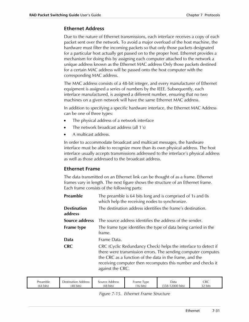
RAD Packet Switching Guide User’s Guide Chapter 7 Protocols
Ethernet 7-31
Ethernet Address
Due to the nature of Ethernet transmissions, each interface receives a copy of each packet sent over the network. To avoid a major overload of the host machine, the hardware must filter the incoming packets so that only those packets designated for a particular host actually get passed on to the proper host. Ethernet provides a mechanism for doing this by assigning each computer attached to the network a unique address known as the Ethernet MAC address Only those packets destined for a certain MAC address will be passed onto the host computer with the corresponding MAC address.
The MAC address consists of a 48-bit integer, and every manufacturer of Ethernet equipment is assigned a series of numbers by the IEEE. Subsequently, each interface manufactured, is assigned a different number, ensuring that no two machines on a given network will have the same Ethernet MAC address.
In addition to specifying a specific hardware interface, the Ethernet MAC Address can be one of three types:
• The physical address of a network interface
• The network broadcast address (all 1’s)
• A multicast address.
In order to accommodate broadcast and multicast messages, the hardware interface must be able to recognize more than its own physical address. The host interface usually accepts transmissions addressed to the interface’s physical address as well as those addressed to the broadcast address.
Ethernet Frame
The data transmitted on an Ethernet link can be thought of as a frame. Ethernet frames vary in length. The next figure shows the structure of an Ethernet frame. Each frame consists of the following parts:
Preamble The preamble is 64 bits long and is comprised of 1s and 0s which help the receiving nodes to synchronize.
Destination address
The destination address identifies the frame’s destination.
Source address The source address identifies the address of the sender. Frame type The frame type identifies the type of data being carried in the
frame. Data Frame Data. CRC CRC (Cyclic Redundancy Check) helps the interface to detect if
there were transmission errors. The sending computer computesthe CRC as a function of the data in the frame, and the receiving computer then recomputes this number and checks it against the CRC.
Preamble (64 bits)
Destination Address (48 bits)
Source Address (48 bits)
Frame Type (16 bits)
Data (358-12000 bits)
CRC 32 bits
Figure 7-15. Ethernet Frame Structure
Chapter 7 Protocols RAD Packet Switching Guide User’s Guide
7-32 IP Protocol
7.9 IP Protocol
Introduction to IP Protocol The Internet system contains a number of interconnected packet networks supporting communication among host computers using the Internet protocols. These protocols include the Internet Protocol (IP), the Internet Control Message Protocol (ICMP), the Transmission Control Protocol (TCP), UDP and application protocols dependent upon them.
All Internet protocols use IP as the basic data transport mechanism. IP is a datagram, or connectionless, internetworking service, that includes provision for addressing, type-of-service specification, fragmentation and reassembly, and security information. ICMP is considered an integral part of IP, although it is architecturally layered upon IP. ICMP provides error reporting, flow control and first-hop gateway redirection.
Reliable data delivery is provided in the Internet protocol suite by transport-level protocols such as TCP, which provides end-to-end retransmission, resequencing and connection control. Transport-level connectionless service is provided by the User Datagram Protocol (UDP).
Networks and Gateways
Constituent networks are generally divided into two classes:
• LANs
• WANs.
In the Internet model, constituent networks are connected together by IP datagram forwarders, called gateways or IP routers.
A gateway is connected to two or more networks, appearing to each of these networks as a connected host. It has a physical interface and an IP address on each of the connected networks. Forwarding an IP datagram requires that the gateway choose the address of the next-hop gateway, or for the final hop, the destination host. This choice, called “routing”, depends upon a routing database within the gateway.
This routing database should dynamically reflect the current topology of the Internet system. To do this , the gateway participates in distributed routing and reachability algorithms with other gateways. Gateways provide datagram transport only, and they seek to minimize the state information necessary to sustain this service in the interest of routing flexibility and robustness.

RAD Packet Switching Guide User’s Guide Chapter 7 Protocols
IP Protocol 7-33
Autonomous Systems
For technical, managerial, and sometimes political reasons, the gateways of the Internet system are grouped into collections called autonomous systems. The gateways included in a single autonomous system are expected to:
• Be under the control of a single operations and maintenance (O&M) organization
• Employ common routing protocols among themselves, to maintain their routing databases dynamically.
A number of different dynamic routing protocols have been developed. The particular choice of routing protocol within a single autonomous system is generically called an interior gateway protocol (IGP).
IP Addressing Architecture IP addresses contain a 32-bit value, and usually is written in decimal dot notation, such as four octets, each separated by a dot.
An IP address is composed of a network ID and host identifications. Each physical network and each host has its own unique network address. Routers and gateways have one or more addresses (depending on the number of interfaces that they have).
Forms of IP Addresses
There are five forms of IP addresses, as follows:
Class A 126 networks, each having up to (16M-2) nodes.
Possible values: (1.0.0.0 - 126.0.0.0)
Class B (16K-2) networks, each having up to (64K-2) nodes.
Possible values: (127.0.0.0 - 191.255.0.0)
Class C (2M-2) networks, each having up to 254 nodes.
Possible values: (192.0.0.0 - 223.255.255.0)
Class D Multicast address.
Possible values: (224.0.0.0 - 240.0.0.0)
Class E Reserved for future use.
Possible values: (241.0.0.0 - 248.0.0.0)

Chapter 7 Protocols RAD Packet Switching Guide User’s Guide
7-34 IP Protocol
For example, the binary address:
10000000 00000111 00001111 00000001
indicates the decimal dot notation, 128.7.15.1 .
This is a Class B address. The network ID is 128.7 and the host ID is 15.1.
10.2.0.37
TO 10.0.0.0Gateway
192.5.48.5192.5.48.1 proNET-10192.5.48.0
proNET-10Host
192.5.48.3 192.5.48.7
128.10.2.3
Ethernet 128.10.0.0
Multi-homedHost
EthernetHost
EthernetHostGateway
128.10.2.8 128.10.2.70 128.10.2.26
Figure 7-16. Sample IP Address Assignment
Special IP Addresses
0.0.0.0 This host.
0.host_number Host on this net.
255.255.255.255 Limited broadcast (local net).
Net_number.255 Directed broadcast for the specified net.
127.anything Loopback (this should never appear on the net).
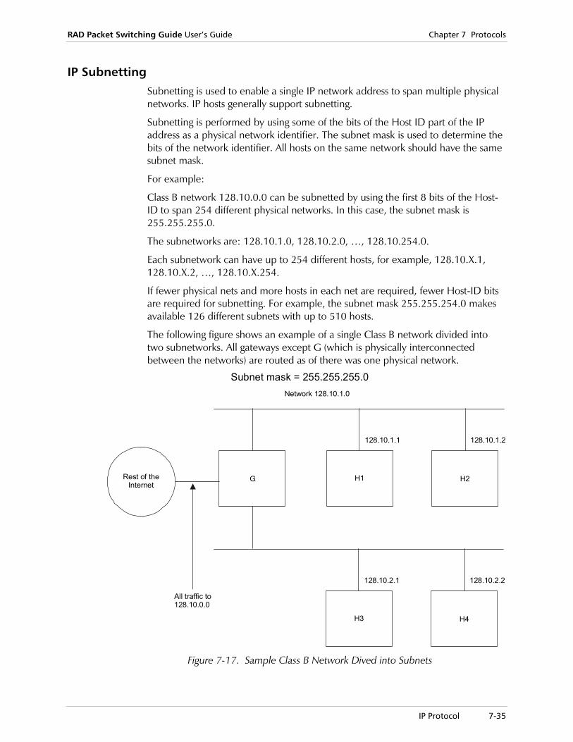
RAD Packet Switching Guide User’s Guide Chapter 7 Protocols
IP Protocol 7-35
IP Subnetting Subnetting is used to enable a single IP network address to span multiple physical networks. IP hosts generally support subnetting.
Subnetting is performed by using some of the bits of the Host ID part of the IP address as a physical network identifier. The subnet mask is used to determine the bits of the network identifier. All hosts on the same network should have the same subnet mask.
For example:
Class B network 128.10.0.0 can be subnetted by using the first 8 bits of the Host-ID to span 254 different physical networks. In this case, the subnet mask is 255.255.255.0.
The subnetworks are: 128.10.1.0, 128.10.2.0, …, 128.10.254.0.
Each subnetwork can have up to 254 different hosts, for example, 128.10.X.1, 128.10.X.2, …, 128.10.X.254.
If fewer physical nets and more hosts in each net are required, fewer Host-ID bits are required for subnetting. For example, the subnet mask 255.255.254.0 makes available 126 different subnets with up to 510 hosts.
The following figure shows an example of a single Class B network divided into two subnetworks. All gateways except G (which is physically interconnected between the networks) are routed as of there was one physical network.
Rest of theInternet
Network 128.10.1.0
Subnet mask = 255.255.255.0
G H2H1
All traffic to128.10.0.0
128.10.1.1 128.10.1.2
H4H3
128.10.2.1 128.10.2.2
Figure 7-17. Sample Class B Network Dived into Subnets
Chapter 7 Protocols RAD Packet Switching Guide User’s Guide
7-36 RIP
7.10 RIP
RIP is a protocol in a series of routing protocols, based on the Bellman-Ford (or distance vector) algorithm. This algorithm has been used for routing computations in computer networks since the early days of the ARPANET. The particular packet formats and protocols described here are based on the “routed” program, which is included with the Berkeley distribution of Unix. It has become a standard for exchange of routing information among gateways and hosts. For this reason it is implemented by most commercial vendors of IP gateways.
RIP is intended for use within the IP-based Internet. The Internet is organized into a number of networks, connected by gateways. The networks are either point-to-point links or more complex networks, such as Ethernet or ARPANET. IP datagrams, addressed to some host, pass through the hosts and gateways.
Routing is the method by which the host or gateway decides where to send the datagram. It can send the datagram directly to its destination, if that destination is on one of the networks that are directly connected to the host or gateway. However, the interesting case is when the destination is not directly reachable. In this case, the host or gateway attempts to send the datagram to a gateway that is near the destination. The goal of a routing protocol is very simple. It is to supply the information that is needed for routing.
When complying with RIP, once a router is installed and has started operating, it sends messages to all of its neighbors. This is necessary in order to update their tables.
RIP forces a router to send update messages every thirty seconds. These messages contain routes that the router knows, and their metrics. If a router does not receive an update message for 180 seconds from another router, it assumes the router to be unreachable. This timeout of 180 seconds allows a router to miss five update messages, without being marked unreachable. This is necessary, since the media might be unreliable and loose datagrams.
Every update message contains a list of the autonomous systems the routers knows to reach and their metrics. If the metric in an update message is lower than the metric in the router’s table, the router updates the metric and the next hop fields in its table.
The packet switching devices support RIP 1 and RIP 2. This support may be configured to ON or Off and modified with some proprietary elements.

RAD Packet Switching Guide User’s Guide Chapter 7 Protocols
Telnet 7-37
7.11 Telnet
The TCP/IP protocol suite includes a simple remote terminal protocol called Telnet.
Telnet enables a user at one site to establish a TCP connection to a login server at a remote site. This involves passing the keystrokes from the user’s terminal directly to the remote machine, as if they were typed at the remote terminal.
Telnet also carries output data from the remote machine back to the user’s terminal.
The Packet Switching devices support both client and server Telnet features.
serverclient
User Terminal
Using NVT Format serversystem
Figure 7-18. Client Server Application (using NVT Format)
The client feature enables the user to connect to a remote Telnet server via a dumb terminal.
Terminalsps/aps/apd
x.25or FR
TelnetServer
RTelnet Client
Figure 7-19. Remote Telnet Server via a Dumb Terminal
The terminal is connected to the SPS via a X.28 asynchronous channel .To open a Telnet session, the user enters the Telnet IP address. For example: Telnet 192.114.24.30. Assuming there is a correct IP routing for the address, a Telnet session is opened to the remote server.
The server feature enables a Telnet client to connect to a remote packet switching device. This may be used as an IP gateway to Packet Switching networks.
sps/aps/apd
x.25or FR
TelnetClient Telnet Server
Figure 7-20. Remote Telnet Client
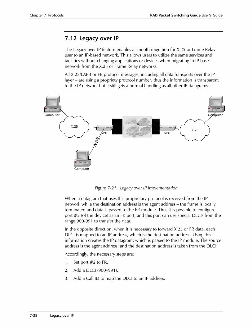
Chapter 7 Protocols RAD Packet Switching Guide User’s Guide
7-38 Legacy over IP
7.12 Legacy over IP
The Legacy over IP feature enables a smooth migration for X.25 or Frame Relay user to an IP-based network. This allows users to utilize the same services and facilities without changing applications or devices when migrating to IP base network from the X.25 or Frame Relay networks.
All X.25/LAPB or FR protocol messages, including all data transports over the IP layer – are using a propriety protocol number, thus the information is transparent to the IP network but it still gets a normal handling as all other IP datagrams.
IPX.25
SPS SPS
Computer
X.28
Computer
X.25
Computer
Figure 7-21. Legacy over IP Implementation
When a datagram that uses this proprietary protocol is received from the IP network while the destination address is the agent address – the frame is locally terminated and data is passed to the FR module. Thus it is possible to configure port #2 (of the device) as an FR port, and this port can use special DLCIs from the range 900-991 to transfer the data.
In the opposite direction, when it is necessary to forward X.25 or FR data, each DLCI is mapped to an IP address, which is the destination address. Using this information creates the IP datagram, which is passed to the IP module. The source address is the agent address, and the destination address is taken from the DLCI.
Accordingly, the necessary steps are:
1. Set port #2 to FR.
2. Add a DLCI (900–991).
3. Add a Call ID to map the DLCI to an IP address.
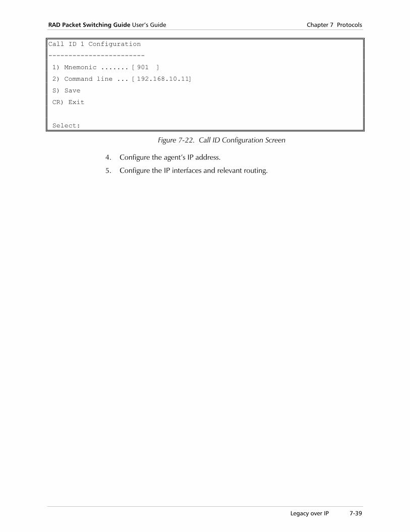
RAD Packet Switching Guide User’s Guide Chapter 7 Protocols
Legacy over IP 7-39
Call ID 1 Configuration
------------------------
1) Mnemonic ....... [901 ]
2) Command line ... [192.168.10.11]
S) Save
CR) Exit
Select:
Figure 7-22. Call ID Configuration Screen
4. Configure the agent’s IP address.
5. Configure the IP interfaces and relevant routing.

Chapter 7 Protocols RAD Packet Switching Guide User’s Guide
7-40 Legacy over IP
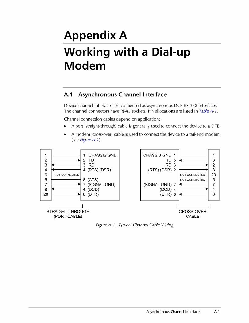
Asynchronous Channel Interface A-1
Appendix A Working with a Dial-up Modem
A.1 Asynchronous Channel Interface
Device channel interfaces are configured as asynchronous DCE RS-232 interfaces. The channel connectors have RJ-45 sockets. Pin allocations are listed in Table A-1.
Channel connection cables depend on application:
• A port (straight-through) cable is generally used to connect the device to a DTE
• A modem (cross-over) cable is used to connect the device to a tail-end modem (see Figure A-1).
1234657820
1 CHASSIS GND 2 TD 3 RD 4 (RTS) (DSR)
8 (CTS) 7 (SIGNAL GND) 4 (DCD) 6 (DTR)
NOT CONNECTED
1328
205746
CHASSIS GND 1TD 5RD 3
(RTS) (DSR) 2
(SIGNAL GND) 7(DCD) 4(DTR) 6
NOT CONNECTED
NOT CONNECTED
STRAIGHT-THROUGH(PORT CABLE)
CROSS-OVERCABLE
Figure A-1. Typical Channel Cable Wiring
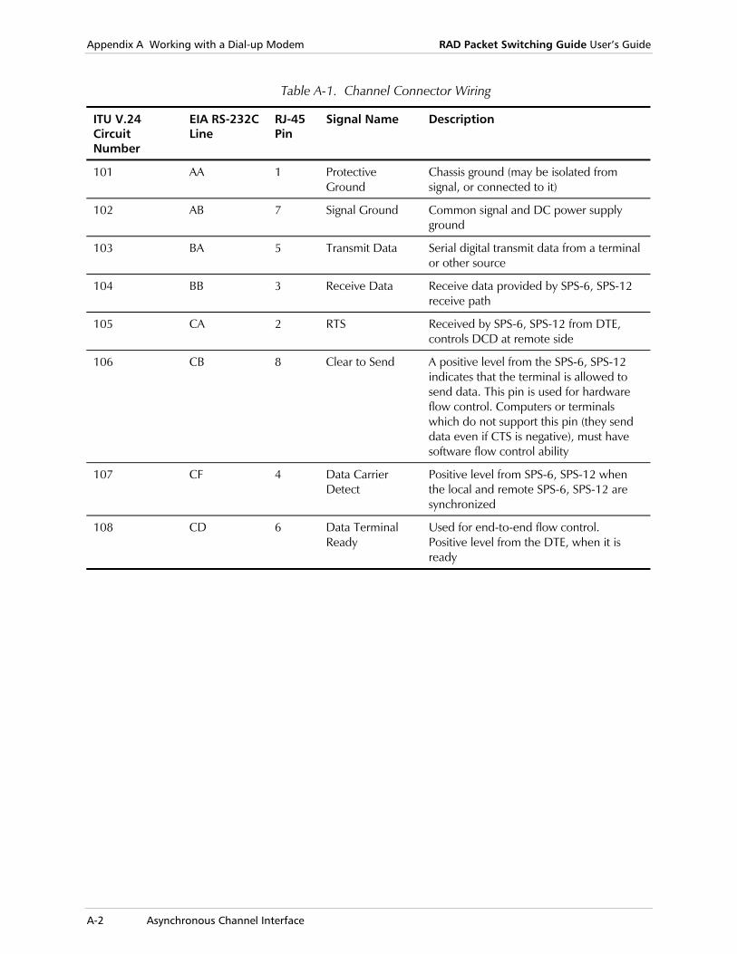
Appendix A Working with a Dial-up Modem RAD Packet Switching Guide User’s Guide
A-2 Asynchronous Channel Interface
Table A-1. Channel Connector Wiring
ITU V.24 Circuit Number
EIA RS-232C Line
RJ-45 Pin
Signal Name Description
101 AA 1 Protective Ground
Chassis ground (may be isolated from signal, or connected to it)
102 AB 7 Signal Ground Common signal and DC power supply ground
103 BA 5 Transmit Data Serial digital transmit data from a terminal or other source
104 BB 3 Receive Data Receive data provided by SPS-6, SPS-12 receive path
105 CA 2 RTS Received by SPS-6, SPS-12 from DTE, controls DCD at remote side
106 CB 8 Clear to Send A positive level from the SPS-6, SPS-12 indicates that the terminal is allowed to send data. This pin is used for hardware flow control. Computers or terminals which do not support this pin (they send data even if CTS is negative), must have software flow control ability
107 CF 4 Data Carrier Detect
Positive level from SPS-6, SPS-12 when the local and remote SPS-6, SPS-12 are synchronized
108 CD 6 Data Terminal Ready
Used for end-to-end flow control. Positive level from the DTE, when it is ready

RAD Packet Switching Guide User’s Guide Appendix A Working with a Dial-up Modem
Asynchronous System User A-3
A.2 Asynchronous System User
For the asynchronous system user, working through a dial-up modem is much the same as working through leased line.
The only difference with leased line use is that the first user that opens a session through the dialed link, will wait up to 2 minutes (dialing time) before the session is opened. All other users that try to open a session, when the link is in the process of dialing, will wait. When the connection is established, all the users will be connected and new users that will try to open a session will succeed.
• To activate this option, open the X.25 Link n Configuration screen and change parameter 23 (Line) from 1024 to 256.
• If the dialed link is to be disconnected after 5 minutes if no session is working on that link, change parameter 23 (Line) from 1024 to 261.
• The backup option is enabled if you define the dialed link in the routing table as the last option for an address (see Routing Table Configuration in Chapter 2).
In this case, if you try to open a session through a link that is not in sync, the switch tries to open a session through its second option in the routing table. If the second option is a dialed link, it is activated. If you selected the 512 option, the dialed link will be disconnected when the leased line is fixed. This allows you to open a session on the leased line.

Appendix A Working with a Dial-up Modem RAD Packet Switching Guide User’s Guide
A-4 V.35 Link Interface
A.3 V.35 Link Interface
The connector of the interface is a 34-pin VAPL female connector, wired as follows:
Table A-2. V.35 Link Interface, Connector Pin Allocations
Pin Designation Direction Function
A FGND --- Frame gound
B SGND --- Signal ground
C RTS OUT Request to send
D CTS IN Clear to send
E DSR IN Data set ready
F DCD IN Carrier detect
H DTR OUT Data Terminal ready
J RI IN Ring indicator
P TD(A) OUT TX data - A wire
R RD(A) IN RX data - A wire
S TD(B) OUT TX data - B wire
T RD(B) IN RX data - B wire
U ETC(A) OUT External TX CLK - A wire
V RC(A) IN RX CLK - A wire
W ETC(B) OUT External TX CLK - B wire
X RC(B) IN RX CLK - B wire
Y TC(A) IN TX CLK - A wire
Z ERC(B) OUT External RX CLK - B wire
AA TC(B) IN TX CLK - B wire
BB ERC (A) OUT External RX CLK - A wire
HH RLB OUT Remote loop
JJ LLB OUT Local loop
KK TM IN Test loop
Direction: IN- input to device OUT- output from device.
Note
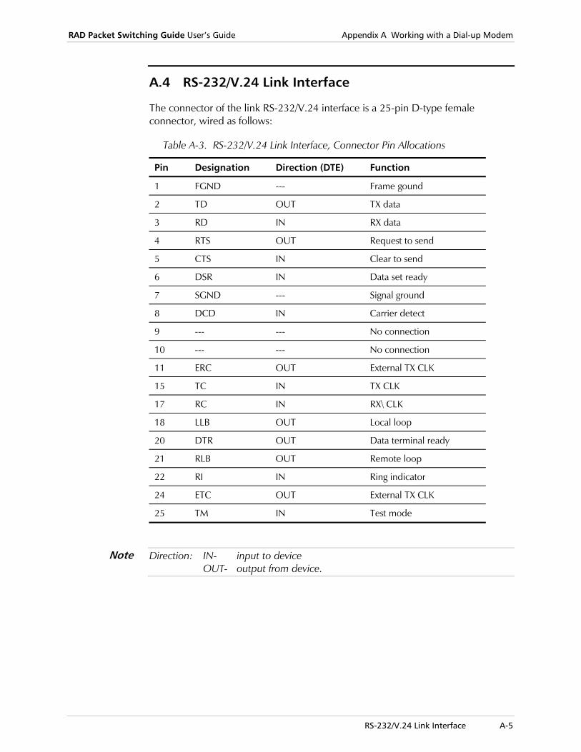
RAD Packet Switching Guide User’s Guide Appendix A Working with a Dial-up Modem
RS-232/V.24 Link Interface A-5
A.4 RS-232/V.24 Link Interface
The connector of the link RS-232/V.24 interface is a 25-pin D-type female connector, wired as follows:
Table A-3. RS-232/V.24 Link Interface, Connector Pin Allocations
Pin Designation Direction (DTE) Function
1 FGND --- Frame gound
2 TD OUT TX data
3 RD IN RX data
4 RTS OUT Request to send
5 CTS IN Clear to send
6 DSR IN Data set ready
7 SGND --- Signal ground
8 DCD IN Carrier detect
9 --- --- No connection
10 --- --- No connection
11 ERC OUT External TX CLK
15 TC IN TX CLK
17 RC IN RX\ CLK
18 LLB OUT Local loop
20 DTR OUT Data terminal ready
21 RLB OUT Remote loop
22 RI IN Ring indicator
24 ETC OUT External TX CLK
25 TM IN Test mode
Direction: IN- input to device OUT- output from device.
Note

Appendix A Working with a Dial-up Modem RAD Packet Switching Guide User’s Guide
A-6 RS-530 Link Interface
A.5 RS-530 Link Interface
The connector of the link RS-530 interface is a 25-pin D-type female connector, wired as follows:
Table A-4. RS-530 Link Interface, Connector Pin Allocations
Pin Designation Direction (DTE) Function
2 TD OUT TX data - A wire
3 RD(A) IN RX data - A wire
4 RTS(A) OUT Request to send - A wire
5 CTS(A) IN Clear to send - A wire
6 DSR(A) IN Data set ready - A wire
7 SGND --- Signal ground
8 DCD(A) IN Carrier detect - A wire
9 RC(B) IN RX CLK - B wire
10 DCD(B) IN Carrier detect - B wire
11 ETC(B) OUT External TX CLK - B wire
12 TC(B) IN TX CLK - B wire
13 CTS(B) IN Clear to send - B wire
14 TD(B) OUT TX data - B wire
15 TC(A) IN TX CLK - A wire
16 RD(B) IN RX data - B wire
17 RC(A) IN RX data - A wire
18 LLB OUT Local loop
19 RTS(B) OUT Request to send - A wire
20 ERC(A) OUT Data terminal ready - A wire
21 RLB OUT Remote loop
22 DSR(B) IN Data set ready - B wire
23 ERC(B) OUT Data terminal ready - B wire
24 ETC(A) OUT External TC CLK - A wire
25 TM IN Test mode
Direction: IN- input to device OUT- output from device.
Note
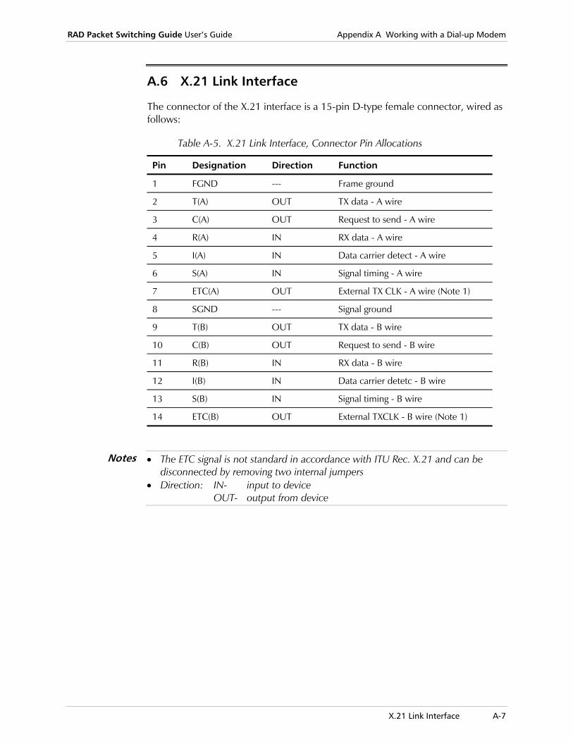
RAD Packet Switching Guide User’s Guide Appendix A Working with a Dial-up Modem
X.21 Link Interface A-7
A.6 X.21 Link Interface
The connector of the X.21 interface is a 15-pin D-type female connector, wired as follows:
Table A-5. X.21 Link Interface, Connector Pin Allocations
Pin Designation Direction Function
1 FGND --- Frame ground
2 T(A) OUT TX data - A wire
3 C(A) OUT Request to send - A wire
4 R(A) IN RX data - A wire
5 I(A) IN Data carrier detect - A wire
6 S(A) IN Signal timing - A wire
7 ETC(A) OUT External TX CLK - A wire (Note 1)
8 SGND --- Signal ground
9 T(B) OUT TX data - B wire
10 C(B) OUT Request to send - B wire
11 R(B) IN RX data - B wire
12 I(B) IN Data carrier detetc - B wire
13 S(B) IN Signal timing - B wire
14 ETC(B) OUT External TXCLK - B wire (Note 1)
• The ETC signal is not standard in accordance with ITU Rec. X.21 and can be disconnected by removing two internal jumpers
• Direction: IN- input to device OUT- output from device
Notes
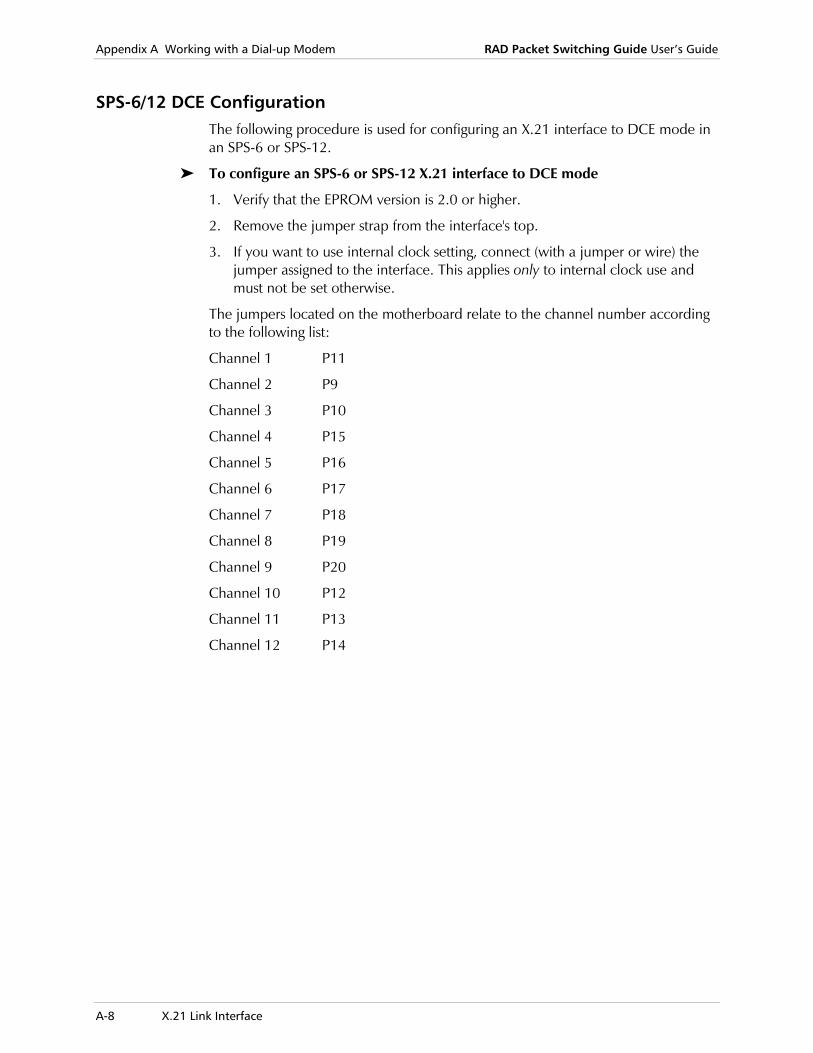
Appendix A Working with a Dial-up Modem RAD Packet Switching Guide User’s Guide
A-8 X.21 Link Interface
SPS-6/12 DCE Configuration The following procedure is used for configuring an X.21 interface to DCE mode in an SPS-6 or SPS-12.
To configure an SPS-6 or SPS-12 X.21 interface to DCE mode
1. Verify that the EPROM version is 2.0 or higher.
2. Remove the jumper strap from the interface's top.
3. If you want to use internal clock setting, connect (with a jumper or wire) the jumper assigned to the interface. This applies only to internal clock use and must not be set otherwise.
The jumpers located on the motherboard relate to the channel number according to the following list:
Channel 1 P11
Channel 2 P9
Channel 3 P10
Channel 4 P15
Channel 5 P16
Channel 6 P17
Channel 7 P18
Channel 8 P19
Channel 9 P20
Channel 10 P12
Channel 11 P13
Channel 12 P14

B-1
Appendix B List of Character Codes Table B-1 lists the character codes used in International Alphabet 5 (IA5) and the corresponding ASCII values.
In addition, Table B-2 of this appendix lists the definitions and common uses of the main control codes.
Table B-1. Character Codes
IA5 Designation ASCII Value Character
0/0 00 NUL
0/1 01 SOH
0/2 02 STX
0/3 03 ETX
0/4 04 EOT
0/5 05 ENQ
0/6 06 ACK
0/7 07 BEL
0/8 08 BS
0/9 09 HT
0/10 10 LF
0/11 11 VT
0/12 12 FF
0/13 13 CR
0/14 14 SO
0/15 15 SI
1/0 16 DLE
1/1 17 DC1 (X-ON)
1/2 18 DC2 (TAPE)
1/3 19 DC3 (X-OFF)
1/4 20 DC4
1/5 21 NAK
1/6 22 SYN
1/7 23 ETB
1/8 24 CAN

Appendix B List of Character Codes RAD Packet Switching Guide User’s Guide
B-2
Table B-1. Character Codes (Cont.)
IA5 Designation ASCII Value Character
1/9 25 EM
1/10 26 SUB
1/11 27 ESC
1/12 28 FS
1/13 29 GS
1/14 30 RS
1/15 31 US
2/0 32 SP
2/1 33 !
2/2 34 *
2/3 35 #
2/4 36 $
2/6 38 &
2/7 39 ‘
2/8 40 (
2/9 41 )
2/10 42 *
2/11 43 +
2/12 44 ,
2/13 45 -
2/14 46 .
2/15 47 /
3/0 48 0
3/1 49 1
3/2 50 2
3/3 51 3
3/4 52 4
3/5 53 5
3/6 54 6
3/7 55 7
3/8 56 8
3/9 57 9
3/10 58 :
3/11 59 ;
3/12 60 <

RAD Packet Switching Guide User’s Guide Appendix B List of Character Codes
B-3
Table B-1. Character Codes (Cont.)
IA5 Designation ASCII Value Character
3/13 61 =
3/14 62 >
3/15 63 ?
4/0 64 @
4/1 65 A
4/2 66 B
4/3 67 C
4/4 68 D
4/5 69 E
4/6 70 F
4/7 71 G
4/8 72 H
4/9 73 I
4/10 74 J
4/11 75 K
4/12 76 L
4/13 77 M
4/14 78 N
4/15 79 O
5/0 80 P
5/1 81 Q
5/2 82 R
5/3 83 S
5/4 84 T
5/5 85 U
5/6 86 V
5/7 87 W
5/8 88 X
5/9 89 Y
5/10 90 Z
5/11 91 [
5/12 92
5/13 93 ]
5/14 94 |
5/15 95 -
6/0 96 GRAVE ACC.

Appendix B List of Character Codes RAD Packet Switching Guide User’s Guide
B-4
Table B-1. Character Codes (Cont.)
IA5 Designation ASCII Value Character
6/1 97 a
6/2 98 b
6/3 99 c
6/4 100 d
6/5 101 e
6/6 102 f
6/7 103 g
6/8 104 h
6/9 105 i
6/10 106 j
6/11 107 k
6/12 108 l
6/13 109 m
6/14 110 n
6/15 111 o
7/0 112 p
7/1 113 q
7/2 114 r
7/3 115 s
7/4 116 t
7/5 117 u
7/6 118 v
7/7 119 w
7/8 120 x
7/9 121 y
7/10 122 z
7/11 123
7/12 124 |
7/13 125 (ALT MODE)
7/15 127 DEL

RAD Packet Switching Guide User’s Guide Appendix B List of Character Codes
B-5
Table B-2. Definitions and Common Uses of Main Control Codes
Value
Designation Definition and Common Use
00 NUL Null Character
01 SOH Start of Header Used at the beginning of a sequence of characters to indicate address or routing information. Such a text is referred to as a Heading. A STX character terminates a heading.
02 STX Start of Text Used at the beginning of a sequence of characters that must be treated as an entity, in order to reach the ultimate destination. Such a sequence is referred to as a text. STX may be used to terminate a sequence beginning with SOH.
03 ETX End of Text Used to terminate a sequence of characters started with STX.
04 EOT End of Transmission Used to indicate the termination of the transmission. A transmission may include one or more records and their associated headings.
05 ENQ Enquiry A character used to request a response from a remote station. The response that a remote station generates is predefined. A typical response would be station address, station status, content of status buffer, etc.
06 ACK Acknowledgement A character sent by the receiving station to the transmitting station to indicate successful reception of a message.
07 BEL Bell Used to activate the “bell” (auditory signaling device) of the receiving device in the remote station.
08 BS Backspace Used to signal the receiving device to go back one character position.
09 HT Horizontal Tab Used to signal the receiving device to move horizontally to a predetermined position (or by predetermined number of character positions).
10 LF Line Feed Used to signal the receiving device to move downwards by one line interval.
11 VT Vertical Tab Used to signal the receiving device to move vertically to a predetermined position.
12 FF Form Feed Used to signal the receiving device to move to the next top of form (or page).
13 CR Carriage Return Used to signal the receiving device to move to the beginning of the line.
14 SO Shift Out.
15 SI Shift In.

Appendix B List of Character Codes RAD Packet Switching Guide User’s Guide
B-6
Table B-2. Definitions and Common Uses of Main Control Codes (Cont.)
Value
Designation Definition and Common Use
16 DLE Data Link Escape Used in the test of a message to change the meaning of a limited number of following characters. Typical applications of this character are to allow the users supplement the control information and obtain a transparent (test) mode of operation.
17 DC1 X-ON Character sent to the receiving device, to signal it to start (or enable) data transmission when using software flow control.
18 DC2 TAPE (AUX ON) Character sent to signal the receiving station to activate an auxiliary unit.
19 DC3 X-OFF Character sent to the receiving device, to signal it to stop data transmission when using software flow control.
20 DC4 AUX OFF Character sent to signal the receiving station to turn off an auxiliary unit.
21 NAK Negative Acknowledge A character sent by the receiving station to the transmitting station.
22 SYN Synchronous Idle Used by synchronous transmission systems to provide messages and character framing and synchronization.
23 ETB End of Transmission Block Used to indicate the end of a sequence of characters started with SOH or STX. The ETB character is used when the block structure is not necessarily related to the processing format.
24 CAN Cancel Used to signal the logical end of media.
25 EM Special Function 1.
26 SUB Special Function 2.
27 ESC Special function 3 (escape).
28 FS Special Function 4.
29 GS Special Function 5.
30 RS Special Function 6.
31 US Special Function 7.
127 DEL Delete Used to signal the deletion of a character.

Routing and Addressing Versatility C-1
Appendix C Routing and Addressing Versatility
C.1 Routing and Addressing Versatility
Introduction RAD Packet Switching devices Ver. 4.0 or higher enable a user to connect to an X.25 network at different locations while maintaining his X.25 address.
The address of a user connecting to an X.25 network would normally depend on his location. The user would be assigned the main address of the switch into which he is connected, and a local subaddress that differentiates him from the other local users.
Connecting the user with a different address would require massive routing changes over the entire network. This unique address would have to be updated at the Routing Tables of any node leading to the user.
Routing versatility is achieved with two new features: Dynamic Routing and Address Affiliation.
Dynamic Routing This feature enables an address search over certain designated links defined as network links. When a call setup packet is received, the address is searched for in the routing table. If no matching address is found the call setup packet is spread out over all links defined as network links. The packet then “travels” simultaneously in different paths. When the address is found the call is established and the search is terminated. If the address is not found the user is notified. The searching operation guarantees the shortest path will be chosen.
When using the Dynamic Routing feature (i.e. designating some links as network links) there is no need to define the distant addresses in the device's routing table. The call setups will be spread out and established over the network links. If a new distant user is added to the network (even when using an unconventional address) only the local device to which the user is connected has to be updated.
The device Routing Table should however contain two entities: local addresses and APD’s connected to the device. The definition of local addresses in the Routing Table will enable communication with async users attached to the device. The definition of the APD’s is required due to the property of APD’s to receive calls without the use of a Routing Table.

Appendix C Routing and Addressing Versatility RAD Packet Switching Guide User’s Guide
C-2 Routing and Addressing Versatility
The address search mechanism generates much traffic over the network in the setup stage. It is recommended to include the distant static addresses (i.e. the conventional X.25 addresses that don't require versatile routing) in the Routing Table. This prevents unnecessary searching traffic.
The network manager may choose to define only some of the links as network links, thus limiting the searching traffic to those links.
The spread procedure should not be used when accessing a public X.25 address. If not all network nodes are RAD devices the procedure will most probably not operate and may even cause undesirable effects.
• To use the Dynamic Routing (the call setup spread mechanism) it is necessary to delete any -all don’t care digit address (XXXXXX)-entry in the Routing Table (entry 2000 in the default configuration). If this entry is not deleted, the device will route the unknown addressed call setup according to that entry and will not spread it out
• When using Dynamic Routing, the network manager should check that each address is uniquely defined (i.e. only one user may use a specific address). Otherwise, the spread procedure may reach an unwanted user.
For more information refer to the example later in this appendix.
Dynamic Routing Configuration
To enable the address search over designated links, the links have to be defined as network links (with call request spread enabled). This is done using the X.25 link configuration menu (see X.25 Link Parameters in Chapter 2). For parameter 15 (Out Call Options), add the Call Request Enabled option (option number 2).
If an -all don’t care digit address- entry exists in the Routing Table, it must be deleted.
To enable the address search over designated links:
1. In the Link Configuration menu, select 3 (Update Link Parameters) and press <Enter>.
The list of links and their protocols appears.
2. Type the X.25 link number to be defined as a Network link (the link over which you want to enable the call request spread function) and press <Enter>.
The X.25 Link n Configuration screen appears.
3. Select 15 (Out Call Options) and press <Enter>.
4. To define the link as a Network Link, add 2 to your current parameter value and press <Enter>.
5. Type S to save the new configuration.
If an -all don’t care digit address (XXXXX)- entry exists in the Routing Table, you must delete it. To delete this entry, select 2 (Delete Routing Table Entry) in the Routing Table Configuration menu. For more information concerning Routing Table configuration, see Routing Table Configuration in Chapter 2.
Notes
RAD Packet Switching Guide User’s Guide Appendix C Routing and Addressing Versatility
Routing and Addressing Versatility C-3
Address Affiliation The address Affiliation feature enables adding a local user to the device through an async channel using a non-conventional address.
Normally, connecting a new local user to the device requires him to be identified with the device X.25 address and a subaddress. The address Affiliation feature enables the user to be reached at an independent X.25 address (an address that is not correlated to the device address or subaddress).
The Affiliation feature offers complementary use of an X.28 command. This command enables an easy user hookup to the device without the need to reconfigure the Routing Table.
To setup a call to one of the affiliated addresses it is necessary to use the complete address in the connect command even on a local call. Usually when calling locally only the subaddress is used. The affiliated address may not be separated into main and sub addresses and must be used as one complete address.
Address Affiliation Configuration
To connect a new user to an async port/channel Using independent X.25 addresses, special Routing Table entries are reserved. These entries differ between device types and configurations. The entries begin at entry number 1000.
These entries correlate with async ports/channels. When an address of a received call setup request fits one of these entries the call will be established. The device will route the call to the async port/channel correlating the specific entry.
For example: In the SPS-9 device, entries number 1001-1009 are correlated with ports 1-9, respectively- providing these ports are configured as async ports. Entry 1000 is correlated with the command port facility - subaddress 00.
The independent X.25 address must be entered into the Routing Table in one of the special entries. This entry must be correlated with the async port/channel to which the user is connected. The link is defined as a local link.
For more information concerning Routing Table configuration, see Routing Table Configuration in Chapter 2.
The RAD packet switching device offers a special X.28 command that enables quick user login. Using this command replaces the Routing Table procedure described above.
Note
Appendix C Routing and Addressing Versatility RAD Packet Switching Guide User’s Guide
C-4 Routing and Addressing Versatility
To set this special routing table configuration:
1. In the Configuration menu, select 9 (Routing Table) and press <Enter>. The Routing Table Entry Configuration menu appears.
2. In the Routing Table Entry Configuration menu, select 1 (Add Routing Table Entry) and press <Enter>.
A list of existing routing table entries appears.
3. Type a number for the new routing table entry and press <Enter>. The entry number must correlate with the async port/channel number to which the user is connected.
For example, In the SPS-9 device entry 1001 correlates with port 1, entry 1002 with port 2 etc. (The entry number is 1000+i, where i stands for the port number.)
4. In the Routing Table Entry screen, set parameter 1 (Destination Link) to L for local.
5. Set parameter 4 (Address) to the user’s address.
6. Type S to save the new routing entry.
Affil Command
The Affil command enables the address affiliation feature. To use the Affil command, you must type it in the user terminal. The terminal must be physically connected to the device through the async port/channel.
To log the user in:
• At the X.28 prompt, type affil address.
The “new user affiliated” message appears.
To log the user out:
• At the X.28 prompt, type daffil.
The “new user deaffiliated” message appears.
Using the AFFIL command is similar to following the procedure for creating the Routing Table entry described above. Using the DAFFIL command is similar to deleting that entry.
Note

RAD Packet Switching Guide User’s Guide Appendix C Routing and Addressing Versatility
Routing and Addressing Versatility C-5
Example Consider the following configuration:
Terminal30001
A
1
1
23
465
2
Terminalsubaddr 66
B
Terminaladdr 777
subaddr 55C
Adds900
X.25Network
SPS-9
Addr 500
APS-8
Addr 3003
DistantSwitch
to otherusers
async async
to otherusers
to otherusers
Figure C-1. Example of Address Configuration and Routing
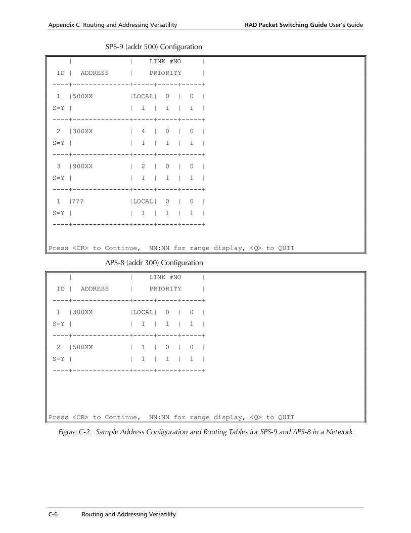
Appendix C Routing and Addressing Versatility RAD Packet Switching Guide User’s Guide
C-6 Routing and Addressing Versatility
SPS-9 (addr 500) Configuration
| | LINK #NO |
ID | ADDRESS | PRIORITY |
----+--------------+-----+-----+-----+
1 |500XX |LOCAL| 0 | 0 |
S=Y | | 1 | 1 | 1 |
----+--------------+-----+-----+-----+
2 |300XX | 4 | 0 | 0 |
S=Y | | 1 | 1 | 1 |
----+--------------+-----+-----+-----+
3 |900XX | 2 | 0 | 0 |
S=Y | | 1 | 1 | 1 |
----+--------------+-----+-----+-----+
1 |??? |LOCAL| 0 | 0 |
S=Y | | 1 | 1 | 1 |
----+--------------+-----+-----+-----+
Press <CR> to Continue, NN:NN for range display, <Q> to QUIT
APS-8 (addr 300) Configuration
| | LINK #NO |
ID | ADDRESS | PRIORITY |
----+--------------+-----+-----+-----+
1 |300XX |LOCAL| 0 | 0 |
S=Y | | 1 | 1 | 1 |
----+--------------+-----+-----+-----+
2 |500XX | 1 | 0 | 0 |
S=Y | | 1 | 1 | 1 |
----+--------------+-----+-----+-----+
Press <CR> to Continue, NN:NN for range display, <Q> to QUIT
Figure C-2. Sample Address Configuration and Routing Tables for SPS-9 and APS-8 in a Network

RAD Packet Switching Guide User’s Guide Appendix C Routing and Addressing Versatility
Routing and Addressing Versatility C-7
SPS-9 Routing Configuration APS-8 Routing Configuration
Links 1 and 3 are defined as network links.
Links 1 and 2 are defined as network links.
Links 5 and 6 are defined as ASYNC links. Terminals B and C were both assigned subaddresses 55 and 56 respectively (the subaddress is configured in the CHANNEL configuration menu. Once links 5 and 6 are defined as ASYNC links they appear as channels 500 and 600 in the channel configuration menus).
Terminal C has, in addition to its subaddress, an unconventional address.
Note that there are no all don’t care digit address- entries in the Routing Tables. This enables the dynamic routing spread facility.
For example:
1. Terminal A generates a call to Terminal C, using one of the following methods: Using C’s conventional address (connect command, such as con 50055).
Using C’s unconventional address (connect command, such as con 777). When the APS-8 does not find a matching address in the Routing Table, it spreads the call throughout links 1 and 2. The call setup is accepted by the SPS-9. The call will then be established and the search procedure terminated.
2. Terminal B generates a call to Terminal C, using one of the following methods: Using C’s subaddress. This is a local call, so the complete address is not
needed.
Using C’s unconventional address (connect command, such as con 777). As this is not a conventional address no shortcuts are allowed. The complete address must be used even though the call is local.
3. A distant terminal logs into the distant switch (upper left side of Figure D-1). The network manager does not need to alter the SPS-9 (addr 500) Routing Table to enable its local users to generate calls to the new terminal. If terminal C wants to generate a call to the new terminal it would simply issue a connect command with the terminal’s address. The call setup will be spread throughout links 1 and 3, and will eventually be established via link 1 (assuming there is no quicker path to reach the distant switch). This providing the links leading to the distant switch are defined as network links. Naturally, the new user would need to be defined in the distant switch.

Appendix C Routing and Addressing Versatility RAD Packet Switching Guide User’s Guide
C-8 Routing and Addressing Versatility
D-1
Appendix D D-Bit Support RAD’s Packet Switching devices Ver 3.0 and higher support the D-bit procedure.
The D-bit (delivery confirmation) is one of the general information identifier bits in the packet information frame. It is used to set either local or end-to-end packet layer delivery acknowledgment. The D-bit may be turned off and on selectively on a per packet basis.
The D-bit is usually set to 0 to indicate that packet layer acknowledgments have only local significant between DTE and DCE.
When the D-bit is set to 1, in a call request data packet, it indicates that acknowledgments have end-to-end signification between source and destination DTEs (for example, when D-bit is set to 1 acknowledgment of packet delivery will be generated from destination DTE to source DTE).
As end-to-end acknowledgment may cause time delays and heavy data flow due to excessive long distance acknowledgments, the D-bit is most efficiently used with the M bit. The M bit is used to indicate continuous data packets. When a large amount of data is divided into smaller packets, each packet, except the last, would have its M bit set on. This is to indicate there is more to come. The last packet would have its D-bit set on to generate delivery confirmation. In this way, delivery indication is achieved without spending extra data flow to indicate the delivery of each and every packet.
The RAD support of the D-bit procedure is transparent to the user and may not be configured. When a packet with a set D-bit is received, the device will forward it according to the standard D-bit procedures without any prior user intervention.

Appendix D D-Bit Support RAD Packet Switching Guide User’s Guide
D-2

Operation E-1
Appendix E RADCONF Program The RADCONF program is used to retrieve and restore the RAD Packet Switching products. RADCONF enables you to save a device configuration and also to restore that particular configuration with the minimum amount of downtime at a later time.
E.1 Operation
The RADCONF program should be implemented only from MS-DOS. If you implement it from Microsoft Windows, the results will be unpredictable.
One of the serial ports (1 or 2) of the computer implementing RADCONF must be connected to the RAD packet switching device in a asynchronous port.
To implement RADCONF:
1. Type Radconf serial_port_number Where the serial_port_number is the PCs serial port number (1 or 2). The RADCONF parameters screen appears (see Figure E-1). For a description of the parameters, see RADCONF Parameters on page E-2.
2. To change one of these parameters, type its number and press <Enter>. Make the change and press <Enter> again.
3. After completing the configuration of the parameters, type Y and press <Enter>. The Options screen appears (see Figure E-2). For a description of the options, see RADCONF Options on page E-3 later in this appendix.
4. Select the option that you want and press <Enter>.
5. To exit the RADCONF program, select 3 (Exit RADCONF) and press <Enter>.
Caution
Note

Appendix E RADCONF Program RAD Packet Switching Guide User’s Guide
E-2 Operation
RADCONF Parameters
STATUS: Waiting for parameters
RAD DATA COMMUNICATIONS LTD.Packet Switching Development GroupUser PC Interface for the RAD Racket Switching devices
V1.0Messages:1. Address : Local 2. Password : None3. Device ID : 4. PC Serial Port : 2Are these parameters acceptable (y/1/2/3/4)?
Input:
Figure E-1. RADCONF Parameters Screen
The three areas of the RADCONF parameters screen are:
Status This area reports the current status of the software. In Figure F-1, the status is waiting for a response from the user.
Messages This area contains RADCONFs messages to the user, usually in the form of a question.
Input The area is for the users parameter/response entry.
The RADCONF screen contains the following parameters
Address Address where RADCONF will configure in order to restore the configuration
Password Current device password.
Device ID Additional means of security. If this is not blank, RADCONF will check that the device to which it connected has this device ID. If it finds a different one, the operation will be terminated. This enables you to double-check that the address matches the device you want to store.
PC Serial Port After opening RADCONF, you can change the target serial port.
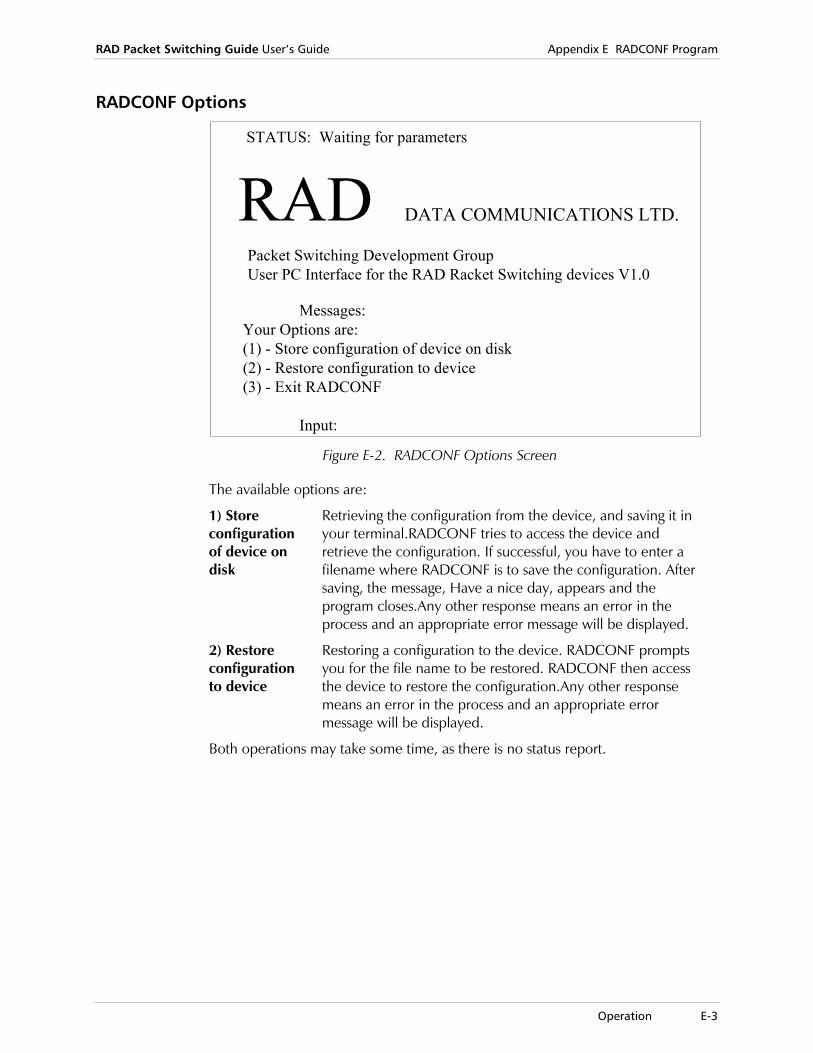
RAD Packet Switching Guide User’s Guide Appendix E RADCONF Program
Operation E-3
RADCONF Options
STATUS: Waiting for parameters
RAD DATA COMMUNICATIONS LTD.
Packet Switching Development GroupUser PC Interface for the RAD Racket Switching devices V1.0
Messages:Your Options are:(1) - Store configuration of device on disk(2) - Restore configuration to device(3) - Exit RADCONF
Input: Figure E-2. RADCONF Options Screen
The available options are:
1) Store configuration of device on disk
Retrieving the configuration from the device, and saving it in your terminal.RADCONF tries to access the device and retrieve the configuration. If successful, you have to enter a filename where RADCONF is to save the configuration. After saving, the message, Have a nice day, appears and the program closes.Any other response means an error in the process and an appropriate error message will be displayed.
2) Restore configuration to device
Restoring a configuration to the device. RADCONF prompts you for the file name to be restored. RADCONF then access the device to restore the configuration.Any other response means an error in the process and an appropriate error message will be displayed.
Both operations may take some time, as there is no status report.

Appendix E RADCONF Program RAD Packet Switching Guide User’s Guide
E-4 Operation

F-1
Appendix F Acronyms ACK Acknowledgement message
AID Address Identifier
ANSI American National Standards Institute
BECN Backward Explicit Congestion Notification
BISYNC Binary Synchronous Communications
CIR Committed Interval Rate
CHAP Challenge Authentication Protocol
CLLM Consolidate Link Layer Management
CRC Cyclic Redundancy Check
CSMA/CD Carrier Sense Multiple Access with Collision Detect
CTS Clear To Send
CUD Call User Data
CUG Closed User Group
DCD Data and Carrier Detect
DCE Data Communication Equipment
DE Discard Eligibility
DLCI Data Link Connection Identifier
DNIC Data Network Identifier Code
DTE Data Terminal Equipment
DTR Data Terminal Ready
EPROM Erasable Programmable Read Only Memory
FECN Forward Explicit Congestion Notification
FEP Front End Processor
FR Frame Relay
FRAD Frame Relay Access Device
HDLC High Level Data Link Control
HPAD Host Packet Assembly Disassembly
IP Internet Protocol
ISDN Integrated Services Digital Network
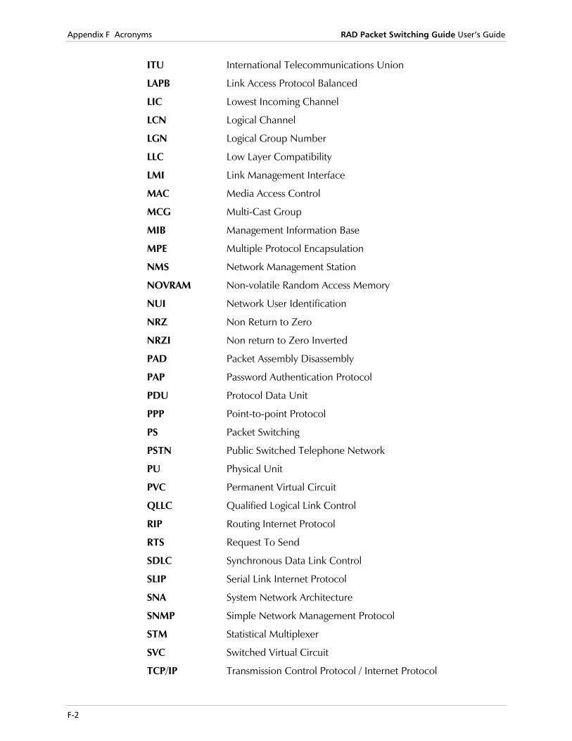
Appendix F Acronyms RAD Packet Switching Guide User’s Guide
F-2
ITU International Telecommunications Union
LAPB Link Access Protocol Balanced
LIC Lowest Incoming Channel
LCN Logical Channel
LGN Logical Group Number
LLC Low Layer Compatibility
LMI Link Management Interface
MAC Media Access Control
MCG Multi-Cast Group
MIB Management Information Base
MPE Multiple Protocol Encapsulation
NMS Network Management Station
NOVRAM Non-volatile Random Access Memory
NUI Network User Identification
NRZ Non Return to Zero
NRZI Non return to Zero Inverted
PAD Packet Assembly Disassembly
PAP Password Authentication Protocol
PDU Protocol Data Unit
PPP Point-to-point Protocol
PS Packet Switching
PSTN Public Switched Telephone Network
PU Physical Unit
PVC Permanent Virtual Circuit
QLLC Qualified Logical Link Control
RIP Routing Internet Protocol
RTS Request To Send
SDLC Synchronous Data Link Control
SLIP Serial Link Internet Protocol
SNA System Network Architecture
SNMP Simple Network Management Protocol
STM Statistical Multiplexer
SVC Switched Virtual Circuit
TCP/IP Transmission Control Protocol / Internet Protocol

RAD Packet Switching Guide User’s Guide Appendix F Acronyms
F-3
TFTP Telnet File Transfer Protocol
TPAD Terminal Packet Assembly Disassembly
TTD Temporary Transmission Delay
UDP User Datagram Protocol
WACK Wait Acknowledgement
XID Exchange Identification

Appendix F Acronyms RAD Packet Switching Guide User’s Guide
F-4
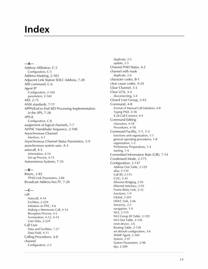
I-1
Index
—A— Address Affiliation, C-5
Configuration, C-5 Address Masking, 2-183 Adjacent Link Station SDLC Address, 7-28 Affil command, C-6 Agent IP
Configuration, 2-160 parameters, 2-160
AID, 2-75 ANSI standards, 7-11 APPN/End to End XID Processing Implementation
in the SPS, 7-28 APS-8
Configuration, C-8 assignment of logical channels, 7-7 ASYNC Handshake Sequence, 2-100 Asynchronous Channel
Interface, A-1 Asynchronous Channel Status Parameters, 5-9 asynchronous system user, A-3 autocall, 4-5
information, 4-14 Set-up Process, 4-15
Autonomous Systems, 7-35
—B— Bisync, 2-82
TPAD Link Parameters, 2-86 Broadcast Address hex FF, 7-28
—C— call
Autocall, 4-14 Facilities, 2-229 Initiation on PVC, 4-6 Making a Mnemonic Call, 4-14 Reception Process, 4-5 Termination, 4-12, 4-14 User Data, 2-229
Call User Data and Facilities, 7-27 Data Field, 4-11
Calling Procedures, 4-8 channel
Configuration, 2-3
duplicate, 2-5 update, 2-5
Channel PAD States, 4-2 channel with mask
duplicate, 2-6 character codes, B-1 clear cause codes, 4-24 Clear Channel, 3-3 Clear LCN, 3-4
disconnecting, 3-4 Closed User Group, 2-45 Command, 4-8
Format of Manual Call Initiation, 4-8 Typing PAD, 4-18 X.28 Call Connect, 4-9
Command Editing characters, 4-18 Procedures, 4-18
Command Facility, 1-1, 1-5 functions and organization, 1-1 general operating procedures, 1-8 organization, 1-3 Preliminary Preparations, 1-4 starting, 1-4
Committed Information Rate (CIR), 7-14 Condensed Mode, 2-175 Configuration, 2-147
Address Out Table, 2-129 alias, 2-134 Call ID, 2-115 CUG, 2-45 Ethernet Bridging, 2-95 Ethernet Interface, 2-93 Frame Relay Link, 2-52 functions, 1-9 Global, 2-201 HDLC Link, 2-66 hierarchy, 2-2 navigation, 1-9 NUI, 2-119 NUI Group ID Table, 2-120 NUI Out Table, 2-126 reset device, 3-6 Routing Table, 2-138 set default configuration, 3-6 SNMP Agent, 2-160 System, 2-97 System Parameters, 2-98 tips, 2-200

Index Packet Switching Guide 5.2 Installation and Operation Manual
I-2
XID Table, 2-153 Congestion, 7-14 CUG
Adding a CUG Subscription, 2-48 Application, 2-45 deleting a CUG subscription, 2-51 Display CUG List, 2-51 Transmission, 2-47 Updating a CUG Subscription, 2-49
CUG Configuration, 2-45 options, 2-45
—D— Data Transfer
stopping, 4-19 DB25 connector, 2-7 D-bit, D-1
procedure, D-1 support, D-1
DCE RS-232 interfaces, A-1 Device Configuration, 2-1 Diagnostics, 6-1
functions, 1-13 Menu, 1-13
Dial Link disconnect a dial link, 3-7
Display Links Parameters, 2-35 Links Protocols, 2-34 Protocol Cut, 5-43
DLCI, 2-52, 7-13 adding, 2-52 deleting, 2-55 Updating, 2-54
DLCI Statistics, 5-27 DTE, 4-4, 4-11, 4-13
Interface States, 4-3 duplicate channel configuration, 2-5 Dynamic Routing, C-1
Configuration, C-3
—E— EBCDIC, 2-230 Enable Software Upgrade, 3-7 Error Handling, 1-8 Establishing the Link Role, 7-29 Ethernet, 7-32
access control, 7-32 Ethernet Address, 7-33 Frame, 7-33 Link Configuration, 2-90 Link Statistics, 5-41 Operation Mode, 2-92 physical medium, 7-32
Event Report Configuration, 2-172 define parameters, 2-172 Parameters, 2-173
—F— Facilities Block, 4-9 Flash Memory Support, 3-7 Forms of IP Addresses, 7-35 Fox test, 6-2 Frame Relay, 7-10, 7-40
Incoming ISDN Call, 7-23 Link Status, 5-24 Nodes, 7-11 Outgoing ISDN Call, 7-23 over ISDN, 7-23 port parameters, 2-60 Protocol Cut, 5-44 Standards, 7-11
Frame Relay Port Parameters updating, 2-55
Funnel, 7-15 adding, 2-148 Configuration, 2-147 deleting, 2-149 displaying, 2-149 updating, 2-148
—G— Global SNA Parameters, 7-26 Group ID Table Entry
adding, 2-121
—H— HDLC, 2-68
Link Status, 5-30 High-Level Data Link Control (HDLC), 7-17 HPAD
Link Parameters, 2-83
—I— Interface Parameters, 2-225 IP
addressing, 2-183 Addressing Architecture, 7-35 Global Configuration, 2-186 Global Parameters, 2-186 Protocol Cut, 5-47 Routing, 2-183 Routing Configuration, 2-185 statistics, 5-47 Subnetting, 7-37
IP interface configuration, 2-187 configuration menu, 2-187 status, 5-50
IP interface entry displaying, 2-189 updating, 2-188
IP Interface Statistics, 5-51 IP Protocol
Networks and Gateways, 7-34 IP Static

Packet Switching Guide 5.2 Installation and Operation Manual Index
I-3
Configuration, 2-193 Configuration menu, 2-193
IP Static entry adding, 2-193 deleting, 2-195 displaying, 2-196 parameters, 2-196 updating, 2-195
ISDN, 2-199, 7-22 Call Check, 6-5 Configuration menu, 2-200 Link Status, 5-33 Routing Table, 2-202 Routing Table Parameters, 2-205
ISDN Accept List Configuration, 2-207 deleting entry, 2-211 displaying entry parameters, 2-211 Parameters, 2-213 updating entry, 2-209
ISDN Algorithm Initiating a Call, 7-22 Receiving a Call, 7-22
ISDN Configuration Operations, 2-200
ISDN link parameters, 2-216 define, 2-216 displaying, 2-218 updating, 2-215
ITUT, 4-9
—L— LANs, 7-34 Legacy over IP, 7-40 Link
Configuration, 2-32 States, 4-3
Link Down, 3-3 disconnecting a link, 3-3
Link Layer, 7-4 Link Up, 3-3 LLC2 over Frame Relay Parameters, 2-231 Local Calls, 4-7 Local PVC Parameters, 2-112 Logical Channels and Logical Channel Groups, 7-6 Loopbacks, 6-4
running a loopback test on a link, 6-4
—M— M bit, D-1 Management Configuration, 2-159
functions, 2-159 Management Station
adding, 2-166 Configuration, 2-166 displaying, 2-168 Parameters, 2-170
Manual Call
Initiation, 4-12 Manual Data Call, 4-11 MCG, 2-179 Menu
Address Out Table Configuration, 2-129 Alias Configuration, 2-134 Call ID Configuration, 2-115 Channel Configuration, 2-3 Channel Protocol Types, 2-4, 2-7, 5-6 Configuration, 1-9, 2-1, 2-18 CUG Configuration, 2-48, 2-51 Diagnostics, 6-1 DLCI Link, 2-54 Ethernet Link Configuration, 2-90 Frame Relay Link Configuration, 2-52 Frame Relay Link n Configuration, 2-52 Funnel Configuration, 2-147, 2-149 IP Configuration, 2-185 IP Interface Configuration, 2-187 IP Static Configuration, 2-193, 2-196 IP Statistics, 5-47 ISDN Accept List Configuration, 2-207 ISDN Configuration, 2-200 ISDN Link Parameters, 2-218 ISDN Routing Configuration, 2-202 Link Configuration, 2-32 Link Types, 2-33 Management Configuration, 2-159 Management Station Configuration, 2-166 MPE Configuration, 2-74 Multicast Group Configuration, 2-178 Multi-Cast Group Configuration, 2-178 NUI Database Configuration, 2-120 NUI Group ID Table Configuration, 2-121 NUI Group Table Configuration, 2-124 NUI Out Table Configuration, 2-126, 2-128 PAP/CHAP Authentication Table, 2-104 Profile Configuration, 2-18 Protocols, 5-43 PVC Configuration, 2-109 Routing Table Entry Configuration, 2-139 SNA Configuration, 2-219 SNA PU Configuration, 2-221 SNMP Agent Configuration, 2-160 Software Upgrade System, 1-7 System Configuration, 2-97 System Control, 1-11, 1-12, 3-1 XID Table Configuration, 2-154
MIB System Group Configuration, 2-164, 2-165 Parameters, 2-164
Mnemonic Call, 4-13 Mnemonic Format, 4-13 MPE
Link Status, 5-35 Port, 2-76 Port Parameters, 2-79 Protocol Frame Structure, 7-20
Multi Point Encapsulation, 2-74

Index Packet Switching Guide 5.2 Installation and Operation Manual
I-4
Multi-Cast Configuration, 2-176 PAD Configuration, 2-177
Multi-Cast Group adding, 2-179 deleting, 2-180 displaying, 2-180 parameters, 2-180 updating, 2-179
Multi-Cast Group Configuration Operations, 2-178
Multiple Sessions, 4-17
—N— network
PVC, 2-114 User ID, 2-119
New Mnemonic Code, 4-13 New Session, 4-17 NOVRAM, 3-5, 3-11
rearranging the non-volatile memory, 3-5 NUI
Configuration, 2-119 database operations, 2-120
NUI Out Table Entry displaying, 2-128
—P— Packet Layer, 7-6 packet switching, 6-4
data calls, 4-8 Packet-Switched Call Processing, 4-2
definitions, 4-2 PAD, 4-19
Code, 4-25 Command Set, 4-19 Control, 4-18 Listing of PAD Command Set, 4-20 parameters, 2-21 Service Signals, 4-20, 4-25
PAD Async Channel Modes, 4-2 PAP/CHAP, 2-108 PAP/CHAP Authentication, 2-103
configuration, 2-103 PAP/CHAP Authentication Entry
displaying, 2-106 Parameters
Address Out Table Entry, 2-133 AID, 2-75, 2-77 Asynchronous Link, 2-72 Bisync Link, 2-82 display the links, 2-35 DLCI, 2-56 Ethernet global, 2-102 Ethernet Link Statistics, 5-42 Frame Relay Global Statistics, 5-45 Frame Relay Link Statistics, 5-25 Funnel, 2-150
HDLC Link Statistics, 5-31 IP interface, 2-190 IP Interface Status, 5-50 ISDN Link Status and Statistics, 5-34 MPE, 2-74 MPE Link Statistics, 5-36 MPE Port, 2-76 Network PVC, 2-114 NUI Group ID Table, 2-124 PAD/FRAD, 2-1, 4-1 PPP channel, 2-14 Routing, 2-142 Routing Table, 5-49 SDLC, 2-70 SLIP channel, 2-13 SNA Link Statistics, 5-38 STM-4, 2-72 STM-8, 2-72 Update Link, 2-34 X.25 Link, 2-36 X.25 Link Statistics, 5-22
password accepted, 1-5 default, 1-5 entering, 1-5 levels, 1-5 setting, 1-5
Permanent Virtual Circuit, 2-109 Physical Layer, 7-4 Ping Test, 6-3 PPP, 2-14 PPP Channel, 2-14 PPP channels, 5-18 Previous Session, 4-17 Priority Parameters, 2-100 Procedures, 4-4
Autocall Initiation, 4-5 Manual Call Initiation, 4-4, 4-8, 4-9
profile configuration, 2-18
Protocol Frame Relay, 7-12 HDLC, 7-17 IP, 7-34 Link Access, 7-3 MPE, 7-20 STM, 7-19
protocol cut screen opening, 5-43
Protocol Type Selection, 5-6 protocols, 7-1 PU configuration concept, 7-25 PU Parameters, 2-223 PU Statistics, 5-39 PVC, 2-109, 4-16
adding, 2-110 deleting, 2-111 displaying, 2-111

Packet Switching Guide 5.2 Installation and Operation Manual Index
I-5
updating, 2-111
—Q— QLLC/X.25 parameters, 2-227
—R— RAD packet switching, 2-152 RAD Packet Switching, 4-17, 4-26 RADCONF, E-1
implementation, E-1 Operation, E-1 Options, E-4 Parameters, E-2
RADCONF Options Restore configuration to device, E-4 Store configuration of device on disk, E-4
RADCONF Parameters Address, E-2 Device ID, E-2 Input, E-2 Messages, E-2 Password, E-2 PC Serial Port, E-3 Status, E-2
recalling the PAD, 4-11 Recalling the PAD, 4-11 Reset, 3-6
resetting the device, 3-6 Reset Statistics, 3-5
statistics counters, 3-5 RIP, 7-38 RIP Protocol, 2-185 RJ-45, A-1 Routing and Addressing Versatility, C-1 Routing Internet Protocol (RIP), 2-185 routing parameters
display, 2-141
—S— Screen
Agent IP Configuration, 2-162 Asynchronous X.28 Channels Status, 5-7 Call ID Configuration, 7-41 Channel Mask, 2-6 Command Facility, 1-5 Default X.25 Link Configuration, 2-36 Display Channels, 2-7 Enable Software Upgrade, 3-7, 3-10 Ethernet Global Parameters, 2-102 Ethernet Link Configuration, 2-95 Ethernet Port Statistics, 5-41 Event Report Configuration, 2-172, 2-173 Fox Test, 6-3 Frame Relay Global Statistics, 5-44, 5-47 Frame Relay Port Configuration, 2-61 Frame Relay Port n DLCI x Statistics, 5-27 Frame Relay Port Statistics, 5-24 Global IP Parameters, 2-186
HDLC Link Configuration, 2-66 HDLC Link Statistics, 5-30 Individual X.28 Asynchronous Channel Status, 5-11 IP Interface n Configuration, 2-190 IP Interface Statistics, 5-51 IP Interface Status, 5-50, 5-51 IP Routing Table Status, 5-49 IP Static Configuration, 2-196 ISDN Accept List Entry Configuration, 2-213 ISDN Call Check, 6-5 ISDN Global Configuration, 2-201 ISDN Link Configuration, 2-216 ISDN Routing Entry Configuration, 2-205 ISDN Status and Statistics, 5-33 Link CUG Subscription, 2-49 Local PVC Configuration, 2-112 Loopback Test, 6-5 Management Station Configuration, 2-170 MIB System Group Configuration, 2-165 MPE Link Statistics, 5-35 MPE Port Configuration, 2-79 Multi-Cast Group Configuration, 2-180 Network PVC Configuration, 2-114 New PVC Configuration, 2-110 NUI Group ID Table Configuration, 2-124 PAP/CHAP Authentication Entry, 2-108 PPP Channel Configuration, 2-15 PPP Channel Statistics, 5-18 Priority Parameters, 2-100 Protocol Configuration, 2-22 PU Interface QLLC/X25 Configuration, 2-227 PU X Interface A LLC2 Configuration, 2-232 RADCONF Options, E-4 RADCONF Parameters, E-2 SDLC Line Configuration, 2-70 SDLC Link Statistics, 5-37 Send Ping, 6-3 SLIP Channel Statistics, 5-16 SLIP Link Configuration, 2-13 SNA Global Configuration, 2-220 SNA Global PU Statistics, 5-46 SNA Link Statistics, 5-37 SNA PU Statistics, 5-40 STM Link Configuration, 2-72 System Parameters Configuration, 2-98 System Status, 5-3, 5-4, 5-6 TFTP Setup, 3-11 TPAD Port Configuration, 2-86 X.25 Link Statistics, 5-21 X.28 Channel Configuration, 2-9 XID Table Configuration, 2-157
SDLC, 2-70 address, 7-28 Link Considerations, 7-30 Parameters, 2-225
SDLC Transmission using Broadcast Address hex FF, 7-28
Set Link Type, 2-33 SLIP, 2-13
channel, 2-13
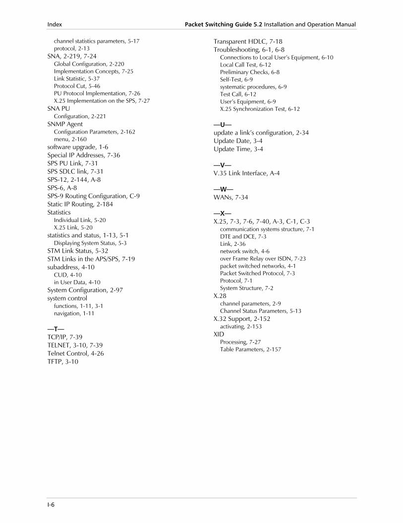
Index Packet Switching Guide 5.2 Installation and Operation Manual
I-6
channel statistics parameters, 5-17 protocol, 2-13
SNA, 2-219, 7-24 Global Configuration, 2-220 Implementation Concepts, 7-25 Link Statistic, 5-37 Protocol Cut, 5-46 PU Protocol Implementation, 7-26 X.25 Implementation on the SPS, 7-27
SNA PU Configuration, 2-221
SNMP Agent Configuration Parameters, 2-162 menu, 2-160
software upgrade, 1-6 Special IP Addresses, 7-36 SPS PU Link, 7-31 SPS SDLC link, 7-31 SPS-12, 2-144, A-8 SPS-6, A-8 SPS-9 Routing Configuration, C-9 Static IP Routing, 2-184 Statistics
Individual Link, 5-20 X.25 Link, 5-20
statistics and status, 1-13, 5-1 Displaying System Status, 5-3
STM Link Status, 5-32 STM Links in the APS/SPS, 7-19 subaddress, 4-10
CUD, 4-10 in User Data, 4-10
System Configuration, 2-97 system control
functions, 1-11, 3-1 navigation, 1-11
—T— TCP/IP, 7-39 TELNET, 3-10, 7-39 Telnet Control, 4-26 TFTP, 3-10
Transparent HDLC, 7-18 Troubleshooting, 6-1, 6-8
Connections to Local User’s Equipment, 6-10 Local Call Test, 6-12 Preliminary Checks, 6-8 Self-Test, 6-9 systematic procedures, 6-9 Test Call, 6-12 User’s Equipment, 6-9 X.25 Synchronization Test, 6-12
—U— update a link’s configuration, 2-34 Update Date, 3-4 Update Time, 3-4
—V— V.35 Link Interface, A-4
—W— WANs, 7-34
—X— X.25, 7-3, 7-6, 7-40, A-3, C-1, C-3
communication systems structure, 7-1 DTE and DCE, 7-3 Link, 2-36 network switch, 4-6 over Frame Relay over ISDN, 7-23 packet switched networks, 4-1 Packet Switched Protocol, 7-3 Protocol, 7-1 System Structure, 7-2
X.28 channel parameters, 2-9 Channel Status Parameters, 5-13
X.32 Support, 2-152 activating, 2-153
XID Processing, 7-27 Table Parameters, 2-157
24 Raoul Wallenberg St., Tel Aviv 69719, IsraelTel: +972-3-6458181, Fax: +972-3-6483331, +972-3-6498250E-mail: , Web site:
Customer Response Form RAD Data Communications would like your help in improving its product documentation. Please complete and return this form by mail or by fax or send us an e-mail with your comments. Thank you for your assistance!
Manual Name: _ _______________________________________
Publication Numb
Please grade the
Installation instruc
Operating instruc
Manual organizati
Illustrations
The manual as a w
What did you like______________ ______________ ______________ ______________ ______________
[email protected] www.rad.com
R
______________________AD Packet Switching Guideer: _ _______________________________________________
man
tions
tions
on
hole
abo____
____
____
____
____
2 5
__________11-252-08/0ual according to the following factors:
Excellent Good Fair Poor Very Poor
❒ ❒ ❒ ❒ ❒ ❒ ❒ ❒ ❒ ❒ ❒ ❒ ❒ ❒ ❒ ❒ ❒ ❒ ❒ ❒
❒ ❒ ❒ ❒ ❒
ut the manual? _________________________________________________________
_________________________________________________________
_________________________________________________________
_________________________________________________________
_________________________________________________________


Error Report Type of Error(s) ❒ Incompatibility with product
or Problem(s): ❒ Difficulty in understanding text
❒ Regulatory information (Safety, Compliance, Warnings, etc.)
❒ Difficulty in finding needed information
❒ Missing information
❒ Illogical flow of information
❒ Style (spelling, grammar, references, etc.)
❒ Appearance
❒ Other _________
Please list the exact page numbers with the error(s), detail the errors you found (information missing, unclear or inadequately explained, etc.) and attach the page to your fax, if necessary. _________________________________________________________________________________________
_________________________________________________________________________________________
_________________________________________________________________________________________
_________________________________________________________________________________________
Please add any comments or suggestions you may have. _________________________________________________________________________________________
_________________________________________________________________________________________
_________________________________________________________________________________________
You are: ❒ Distributor
❒ End user
❒ VAR
❒ Other ________________________
Who is your distributor? _______________________________
Your name and company: ___________________________________________________________
Job title: __________________________________________________________________________
Address: __________________________________________________________________________
Direct telephone number and extension: _______________________________________________
Fax number: ______________________________________________________________________
E-mail: _____________________________________________________________________


900 Corporate Drive, Mahwah, N.J. 07430, Tel: (201) 529-1100
24 Raoul Wallenberg Street, Tel Aviv 69719, Israel, Tel: 972-3-6458181
NORTH AMERICA HEADQUARTERS:
INTERNATIONAL HEADQUARTERS:
Publication No. 211-252-08/05
www.rad.com
Fax: 972-3-6498250, 972-3-6474436, Email: [email protected]
Toll Free: 1-800-444-7234, Fax: (201) 529-5777, Email: [email protected]