rack-based i/o - abb group a power supply unit psf. for a sattcon 35 system the control unit cu45 is...
TRANSCRIPT

I/O System
Rack-based I/O
The rack-based I/O system consists of a central rack and one or two 19 inch expansion racks intended for double size Euro boards. Each rack is equipped with a power supply unit PSF.
For a SattCon 35 system the control unit CU45 is connected to the central rack.
For a Series 200 system connected to a central rack-based I/O, a rack adapter board 200-RANN is mounted in the central rack. This board communicates with the Series 200 CPU via the system bus.
For a Series 200 system connected to a remote rack-based I/O, a rack adapter board 200-RACN is mounted in the central rack. This board communicates with the Series 200 via the ControlNet™ network.
Two expansion racks can be connected to the central rack in a central I/O system and one in a remote I/O system. Each expansion rack is equipped with a bus decoder board PBAD, which communicates with CU45, 200-RANN or 200-RACN in the central rack through a parallel bus cable.
The rack-based system is intended for industrial use and meets the EMC directive 89/336/EEC and the Low Voltage Directive, LVD, 73/23/EEG.
The rack-based I/O has the following main features:
High density I/O system Replacement with power on Large number of I/O boards and
accessories Central or Remote I/O Compatible with both SattCon 35
and Series 200 Digital and analogue I/O boards are
galvanically separated Easy connection of shielded cables Simple upgrading of older I/O
systems

ll
l e
rd
d
e e
e
Bus decodersPBADBus decoder board including bus interconnection socket XPIOS. Handles analogue and digital communication between the central rack and the expansion rack. Also supervises the expansion rack’s internal bus.
The board is powered by +12 V DC from the power supply unit PSF.
Two LEDs on the front indicate power and error.
Two switches on the front are intended for fault diagnosis in the system. The Run/Reset switch resets athe outputs in the expansion rack. TheEnable/Disable switch disconnects a faulty rack for diagnostics without shutting down the rest of the system.
A DIP switch on the side of the boarddetermines the identity of connected expansion racks.
200-RANNRack adapter board for Series 200 system. Handles the communication between system Series 200 and centrarack-based I/O system, and controls thscanning of digital and analogue I/O signals on the local I/O bus.
Each 200-RANN can handle three racks – the central rack where it is installed and two expansion racks.
The board is powered from two sources. Series 200 powers the onboaCPU, memory and related logic whereas the PSF powers the interfacebetween the CPU part of the board anthe local I/O bus.
Three LEDs on the front indicate fail,power and disabled I/O copy (stop).
200-RANN/ARack adapter board 200-RANN with analogue to digital converter, ADSF, included.
2
200-RACNRack adapter board for Series 200 system. Handles the communication between system Series 200 and remotrack-based I/O system, and controls thscanning of digital and analogue I/O signals on the local I/O bus.
Each 200-RACN can handle two racks – the central rack where it is installed and one expansion rack.
The board is powered from the PSF power supply.
Five LEDs on the front indicate fail, power, disabled I/O copy (stop) and communication status.
Two connectors and the ”MODE” rotary switch on the front are used for test and service purposes only.
The other two rotary switches on thefront are used to set the network nodeaddress.
200-RACN/ARack adapter board 200-RACN with analogue to digital converter, ADSF, included.
Power supplyPSFPower supply unit for the PIOS35 rack.One is required in each rack.
The board is powered either from 230 VAC mains or from a separate 24 V DC power unit and produces 5 VDC and 12 V DC, together with a power failure signal.
Maximum load is 50 W when supplied with 230 VAC and 70 W at 24 V DC.
Four LEDs on the front panel indicatesupply for +5 V, +5 VL, +12 V and power failure.
Four sockets for test purposes are located next to the LEDs.
Mains supply selection 110, 220/230or 240 V is made with a switch on the side of the board.
The mains supply is protected by a fuse fitted in the front for easy access.
The secondary side of the mains transformer and the 24 V DC source aralso protected by fuses, located on theside of the board.

l
230V
IAPG
r
o
I/O boardsGeneral informationBoards can be replaced during operation. The switch on the front panel should be set in the “0” position, wherethe input status is frozen in the centralunit and the outputs are set to zero. During normal operation, the switch should be in the “1” position.
LEDs on the front of the board indicate input/output status. The octal address of the input/output is marked beside each LED.
IDPG24 / IDPG48Digital input board with 32 direct current inputs using positive logic. Theinputs are galvanically isolated with optocouplers. The board is available intwo versions for signal levels of 24 and48 V.
IDPG may be used in applications where the plant 0 V is not connected tothe system 0 V, or where there is a special requirement for galvanic signaisolation. IDPG is used to interface signals from devices such as limit switches, photocells etc.
IAPG 230Digital input board with 16 AC inputs (230 V) using positive logic. The inputsare galvanically isolated with optocouplers.
IAPG 230 is used to interface signalsfrom devices such as power switches,relay contacts etc.
3
ODPG.8Digital output board for DC voltage with 32 optocoupled outputs, divided into four separate groups of eight. Themaximum output capacity is 0.8 A per output, subject to maximum 3.2 A per group and 8 A for the entire board.
ODPG.8 is designed for supply voltages between 10–60 V. Since the four groups are completely separated from each other, it is possible to use foudifferent supply voltages for the same board.
Several outputs can be connected tothe same load if they are fed from the same voltage source. If not, they need thave a protective diode in series with the output.
ORG24Digital output board with 16 relay outputs. The relays have single-pole change-over contacts and are providedwith varistor protection.
Maximum relay contact current is 2 Aand maximum relay contact voltage is 250 VAC alternatively 120 V DC.
The supply voltage to the relay coils (24 V DC) is connected to a terminal located on the rear side of the rack.
ODSGDigital short-circuit proof output board with two groups of 16 optocoupled outputs powered by an external supply(+19–30 V DC). Each group is monitored by an overload/short circuit detection bistable. The maximum loadis 0.8 A for each output and 16 A for thecomplete board.
ODSG is intended for loads such as lamps, relays, solenoid valves etc.
When an overload or short circuit condition occurs, the output is switchedoff and the LED for the corresponding channel dims. If the Man/Auto input is active, a yellow LED for that group lights.

,
d
e
h
l
r d
t
et
h
e U
s.
IPA4IPA4 is a digital input board designed to count pulses. The maximum pulse frequency is 10 kHz.
IPA4 has four inputs, each with an 8-bit counter, capable of counting up to 255 pulses. The inputs can be combined in pairs to make two 16-bit counters with a capacity of up to 65535 pulses.
To suppress electrical interference, transmitters with complementary signals should be used.
Phase displaced pulse trains can be used for up/down-counting. The counters can be started, stopped and reset individually.
The common signal reference voltage level can be adjusted and detection of positive and/or negative-going edges can be selected individually for each input.
IPA4 can be used in applications for pulse counting, quantity counting, positioning and speed calculation.
16 LEDs on the front panel show the four counter channels, each with two inputs A and B. The inputs A and B can be combined in different ways, to measure motion in two directions, for instance.
Three sockets for test purposes are located on the front.
The counter channels also have gate inputs to start and stop the counting, and clear inputs to reset the respective counter.
All the input circuits are provided with comparators for transmitters with complementary signals, a means to effectively suppress electrical noise.
IBAAnalogue input board with eight inputs. IBA can either be used on its own or with associated modules. The plug-in modules are for galvanic isolation (MCVG), differential input (MCV200), temperature measurement (MP, MN) or resistance measurement (MR).
When IBA is used without associated modules, the following inputs can be connected: 0–20 mA, 4–20 mA, 0–10 V0–5 V and 1–5 V. Each channel is individually selectable by straps, located on the board.
IBA has high flexibility, very high repeatability and high temperature stability.
If the LED input (current) is used, theintensity of the LED varies with the value of the input signal.
4
OCAHGAnalogue output board with four channels for voltage signals 0–10 V ancurrent signals 0–20 or 4–20 mA, selectable with straps on the board. Thresolution is 8 bits.
The analogue circuits are electricallyisolated from the digital control logic and the control system. The channels are not galvanically separated from eacother.
OCAHG generates analogue signalsto control devices, instruments, etc. Bymeans of the signals DDC and MAN, control can either be automatic (from the control system) or manual via the INCREASE/DECREASE inputs.
Manual control can be executed froma hand module, push-buttons or a digitaoutput board.
OCAHG retains its output values in the event of a CPU failure.
OCVAAnalogue output board with two channels for current signals 0–20 mA o4–20 mA and voltage signals ±10 V or0–10 V. The various ranges are selecteusing connections in the process connector cable.
Each channel can supply both currenand voltage output signals at the sametime. When using a current output the corresponding voltage range must be sto 0–10 V.
The analogue circuits are electricallyisolated from the digital control logic and the control system. The channels are not galvanically separated from eacother.
OCVA can be set up so that the outputs either go to zero or remain at thselected safety state values during CPshut down.
The board has 12-bit resolution for the ±10 V ranges and 11-bit resolutionfor the other current and voltage range

A
ccessoriesOrder codes Function
PIOS/R Basic rack PIOS35 with address panel, power supply PSF and 200-RANN.
PIOS/RA Basic rack PIOS35 with address panel, power supply PSF and 200-RANN/A.
PIOS/RC Basic rack PIOS35 with address panel, power supply PSF and 200-RACN.
PIOS/RCA Basic rack PIOS35 with address panel, power supply PSF and 200-RACN/A.
PIOS/P Basic rack PIOS35 with address panel, power supply PSF, bus interconnec-tion socket XPIOS and bus decoder board, PBAD (also includes screws and mounting devices).
PIOS35 Empty basic rack (for use as expan-sion or central rack).
XPIOS Bus interconnection socket. To be mounted on the rear part of the rack to enable connection of two bus cables to PBAD. Always included with PBAD.
ADSF Central A/D converter. To be mounted on rack adapter board 200-RANN.
IOC351.0M Assembly kit with the following parts: an expansion cable (1 metre) connect-ing the central rack to the first expan-sion rack, a bus extension unit XPBAD, a connector and a cover.
IOC352.5M D:o 2.5 metre.
CPIOS1.0M Cable (1 metre) for parallel bus con-nection between two expansion racks.
CPIOS2.5M D:o 2.5 metre.
200-CBR/R600Cable (0.6 metre) for connecting the Series 200 system to the rack adapter board 200-RANN located in a central rack.
200-CBR/R1000 D:o 1 metre.
Modules for IBA
MCV200
MCVG
MP
MN
MR
Five accessory modules for analogue input board IBA:
Analogue module which permits up to 200 VDC common-mode voltage for each channel, individually.
Analogue module which provides indi-vidual galvanic isolation of up to 750 VDC per channel.
Measures temperature with a Pt100 sensor. MP is linearized. Six ranges.
Measures temperature with a Ni1000 sensor. MN is not linearized.
Measures resistance and is used for position sensing, pressure measure-ment etc. Three ranges.
PTU2 Two ready wired I/O connectors with cables and screw terminal blocks mounted on an aluminium profile.
200-MOUNTKIT Mounting kit for mounting Series 200 central system in a 19” rack.
PTC Digital simulation board with a panel which has 32 switches for simulation of digital signals.
IVAPOT Analogue simulation board with eight potentiometers for simulation of ana-logue signals.
Order codes Function
5
6
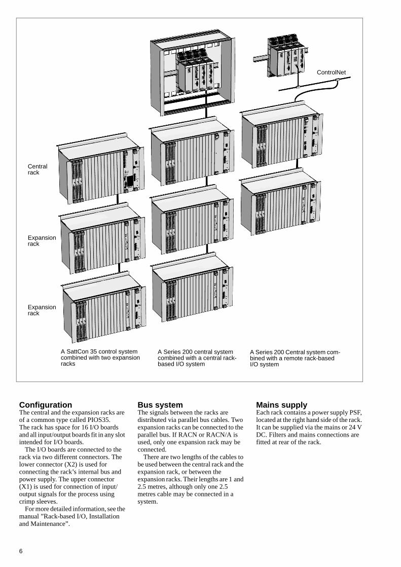
A SattCon 35 control system combined with two expansion racks
A Series 200 central system combined with a central rack-based I/O system
A Series 200 Central system com-bined with a remote rack-based I/O system
Expansion rack
Expansion rack
Central rack
ControlNet
ConfigurationThe central and the expansion racks are of a common type called PIOS35. The rack has space for 16 I/O boards and all input/output boards fit in any slot intended for I/O boards.
The I/O boards are connected to the rack via two different connectors. The lower connector (X2) is used for connecting the rack’s internal bus and power supply. The upper connector (X1) is used for connection of input/output signals for the process using crimp sleeves.
For more detailed information, see the manual ”Rack-based I/O, Installation and Maintenance”.
Bus systemThe signals between the racks are distributed via parallel bus cables. Two expansion racks can be connected to the parallel bus. If RACN or RACN/A is used, only one expansion rack may be connected.
There are two lengths of the cables to be used between the central rack and the expansion rack, or between the expansion racks. Their lengths are 1 and 2.5 metres, although only one 2.5 metres cable may be connected in a system.
Mains supply Each rack contains a power supply PSF, located at the right hand side of the rack. It can be supplied via the mains or 24 V DC. Filters and mains connections are fitted at rear of the rack.

Technical data
General
TemperatureOperating
Non-operating
+5°C to +55°C (max. mean tem-perature over 24 hours is 50°C)–25°C to +70°C
Humidity Max. 90%, non-condensingProtection class IP20Design standard Fulfils the EMC directive 89/336/
EEC and the Low Voltage Direc-tive, LVD, 73/23/EEG for indus-trial environments
Rated current for crimp sleeves 5 ABoard type Double size Euro boardOrder code
Manual “Rack-based I/O Installation and Maintenance” RACKIO-IME
PBAD
The inaccuracy of bus decoder board PBAD is insignificantly low compared with that of the analogue boards and A/D con-verters, i.e. the board has no influence on the overall technical specificationCurrent consumption from PSF Max. 50 mADimensions (incl. panel) H 262 x W 20 x D 190 mmOrder code PBAD
200-RANN
Current consumption from NNbus200-RANN200-RANN/A
400 mA600 mA
Current consumption from PSF Max. 100 mADimensions (incl. panel) H 262 x W 60 x D 190 mmOrder codes 200-RANN
200-RANN/A
200-RACN
Number of channels 1Communication protocol ControlNetSerial interface Separated via a signal trans-
formerSpeed of transfer 5 Mbit/sec.Power supply From Power supply unit PSFCurrent consumption
200-RACN200-RACN/A
400 mA/+5V; max.100 mA/+12V600 mA/+5V; max.100 mA/+12V
ControlNet connector BNC 75 ΩDimensions (incl. panel) H 262 x W 60 x D 190 mmOrder codes 200-RACN
200-RACN/A
PSF
Supply voltageMains supply
Frequency24 V DCRipple on 24 V DCCurrent consumption (nominal input voltage)230 V AC mains24 V DC supply
110/220/240 V AC +15/–10% selectable, 220 V AC accepts also 230 V AC +10/–15%50 Hz ±5% or 60 Hz ±5%24 V DC +20/–15% excl. ripplePeak 5% of nominal voltage
Typ. 0.5 A for max. load 50 WTyp. 3.5 A for max. load 70 W
Output voltagesa
a. (the total output power can limit the current)
+5 V DC, +5 VL
Max. current output
Min. current output+12 V DC
5.1 V DC +0.1/–0.3 V DC during normal operation4 A (+5 V DC and +5 VL com-bined)0.2 A12.5 V DC ±5 V DC max. 4 A, min. 0.2 A
Output powerMains supply24 V DC
Max. 50 WMax. 70 W
Continuous working voltage 240 V ACIsolation test voltage 1776 V AC for one second,
between mains input and protec-tive ground and DC side.
Front panel temperature < 40°C above ambientDimensions (incl. panel) H 262 x W 40 x D 190 mmOrder code PSF
7

IDPG24 / IDPG48
Number of inputs 32Input voltages
IDPG24IDPG48
24 V DC +20/–25%48 V DC +20/–25%
Overvoltage rating 220 V AC max. 10 s.Input current “1” level Typ. 10 mA (+20/–25%)Filter time constant Typ. 10 msLogical levels
IDPG24IDPG48
0 < 5 V DC, 1 > 16 V DC0 < 10 V DC, 1 > 32 V DC
Continuous working voltage
< 75 V DC relative to system logic
Isolation test voltage 500 V DC (one minute)Current consumption 40 mA (internal +12 V DC)System power 4 mA/active input +5 VL (= typ.
130 mA, max. 190 mA +5 VL)Miscellaneous Galvanic isolation in pairs with
one common connectionDimensions (incl. panel) H 262 x W 20 x D 190 mmOrder codes IDPG24
IDPG48
IAPG230
Number of inputs 16 optocoupledInput voltage 230 V AC +10/–15%Overvoltage rating 500 V AC max. 10 s.Input current for activated input
6.5–14 mA, typ. 10 mA (230 V AC +10/–15%, 47–63 Hz)
Frequency range 47–63 HzFilter time constant Typ. 20 msLogical levels Typ. 0 < 70 V DC, 1 > 130 V DCContinuous working voltage 230 V ACIsolation test voltage 1752 V AC for one second,
between inputs and between any system logic and front panel.
Current consumption 20 mA (internal +12 V DC)System power 5–15 mA/active input +5 VL (typ.
160 mA, tot. max. 80–240 mA)Dimensions (incl. panel) H 262 x W 20 x D 190 mmOrder code IAPG230
ODPG.8
Number of outputs 32 optocoupledNumber of separate groups 4Supply voltage 10–60 V DC. The groups can
have common or separate sup-plies
Peak voltage 75 V DC (mean value), max. 60 V DC as above
8
Load current Max. 0.8 A per outputMax. 3.2 A per groupMax. 8 A per board
Surge current Max. 2 A for 50 msLeakage current Max. 2 mA typ. < 0.5 mARecommended external fuses 3.2 A fast-blow per groupVoltage drop, output Max. 2.5 V DC typ. < 1 V DCActivation time Max. 10 µs typ. 5 µsDeactivation time Max. 400 µs typ. 200 µsContinuous working voltage
< 75 V DC relative to system ground
Isolation test voltage 500 V DC for one minute, betweeen each group and sys-tem logic
Current consumption 30 mA (internal +12 V DC) 2–7 mA/active output (+5 VL). Totally 60–230 mA, typ. 140 mA
Dimensions (incl. panel) H 262 x W 20 x D 190 mmOrder code ODPG.8
ORG24
Number of outputs 16Relay coil supply 24 V DCCurrent drawn from relay supply (VR) per energized relay coil
17–25 mA at 24 V DC(VR = 24 V DC, +20/–15%)
Contact voltage ratingsACDC
250 V max. 120 V max.
Contact current ratings (resistive load)ACDCDC
2 A max. 2 A max. (24 V DC +20%)0.6 A max. (48 V DC +20%)Internal varistor for surge sup-pression. External overload pro-tection required for all loads and external surge suppression for inductive loads
Min. contact current 100 mA at 12 V DCRelay operating time 15 ms max., typ. 8 msRelay release time 10 ms, typ. 4 msContact bounce period 2.5 ms max.Relay working life (resistive load)
DCAC
2 A: 1500000 operations2 A: 800000 operations
Continuous working voltage 250 V AC max.Isolation test voltage 1800 V AC for one second,
between each individual relay contact and between any relay contact and system logic or front panel.
Current consumption 20 mA (+12 V DC). 5–15 mA/active output, typ. 10 mA (+5 VL). Totally 80–240 mA, typ. 160 mA
Dimensions (incl. panel) H 262 x W 20 x D 190 mmOrder code ORG24

ODSG
Number of outputs 32 optocoupled and 2 optocou-pled error bistables
Number of inputs 2 optocoupled 24 V DC. 10 mA reset signals
External supply voltage 19–30 V DCVoltage limit Max. 50 V DC for 1 min. (25°C)Load current Max. 0.8 A per output
Max. 16 A per boardShort circuit current Typ. 4 A, max. 10 A, fuse trip
delay ≤ 20 ms (25°C)Leakage current Max. 100 µA, typ. 10 µA. Typical
value for a short circuited output is 10 mA
Recommended external fuses 16 A (slow) per board Resistance Typ. 0.4 Ω, max. 0.6 Ω at 0.5 A.
Typ. 0.6 Ω at 0.8 A (25°C)Activation time Typ. 10 µsDeactivation time Typ. 150 µsCurrent consumption
System (12 V DC)LED (5 VL)
40 mA7 mA/active output, typ. 140 mA
Continuous working voltage
< 75 V DC relative to system ground
Isolation test voltage 500 V DC for one minute, between I/O and system logic
Dimensions (incl. panel) H 262 x W 20 x D 190 mmOrder code ODSG
IPA4
Number of inputs 4 (with 8-bit counter)2 (with 16-bit counter)
Galvanic isolation NoInput impedance 1 kΩ or ≈ 90 ΩPower dissipation Max. 0.25 W across connected
terminating resistorMax. pulse amplitude, complementary inputs
33 V DC (1 kΩ input impedance) or 10 V DC (90 Ω impedance)
Max. pulse amplitude, non-complementary inputs 24 V DCInput voltage difference Min. 1 V DC rel. inverted input or
rel. transition levelMax pulse frequency 10 kHzProcess cabling Twisted-pair cable with individual
shielding for each pair of wiresCurrent consumption 150 mA (+12 V DC, 1.8 W)Reference voltage level 0–10.5 V DC, adjustableDimensions (incl. panel) H 262 x W 20 x D 190 mmOrder code IPA4
IBA
Number of inputs 8Input impedance
CurrentVoltage
250 Ω without LED300 kΩ
Voltage drop Max. 5 V DC without LEDMax. 8 V with LED
Accuracy ±0.2% FS at 25°CTemperature stability ±0.002% FS per °CMax. permanent permissible overload
CurrentVoltage
30 mA30 V DC
Input type Single-ended common typeInput filter (time to 63% of FS)
70 ms ± 10% filter of first order. Breaking point at ≈ 2.3 Hz
Input connector Harting, crimp-pinCrosstalk between channels 79 dB attenuationNon-linearity 0.02% FSRepeating accuracy 0.001% FSRFI immunity Error of less than 0.8% of FS at
10 V/m, 27–1000 MHzCurrent consumption Typ. 90 mA (+12 V DC) for the
board. When modules are used, the current consumption increas-es
Dimensions (incl. panel) H 262 x W 20 x D 190 mmOrder code IBA
IBA-module MCV200
Common mode suppression
72 dB attenuation with 0–10 V ± 5 V DC, otherwise 66 dB
Continuous working voltage
< 75 V DC relative to system ground
Common mode voltage relative to ground Max. 200 V DC (by design)Impedance
Common mode Differential mode
400 kΩ800 kΩ
Temperature stability Max. ±0.003% FS per °CCurrent consumption 4 mA (+12 V DC ) per moduleMiscellaneous All other technical data are the
same as for the IBADimensions H 107 x W 18 x D 13 mmOrder code MCV200
9

IBA-module MCVG
Continuous working voltage
< 75 V DC relative to system ground
Common mode voltage relative to ground
750 V DC without LEDs (by design)250 V DC with LEDs (by design)
Common mode suppression 94 dB attenuationLeakage current 220 V, 50 Hz, 2 µA typ.Accuracy ±0.3% FS at 25°CTemperature stability Max. ±0.002% FS per °CNon-linearity Max. 0.1% FSCurrent consumption 18 mA (+12 V DC) per moduleMiscellaneous All other technical data are the
same as for the IBADimensions H 107 x W 18 x D 13 mmOrder code MCVG
IBA-modules MP, MN and MR
Input impedance Min. 10 MΩAccuracy at 25°C
MP100-MP400
MP600
MN80
MR100-MR1000
±0.4% FS, DIN 43760, α =0.00385±0.6% FS, DIN 43760, α =0.00385Follows the curve, ±0.4% FS
1000 Ω = 0°C871.7 Ω = –30°C1390.1 Ω = 80°C±0.5% FS
Temperature stability Max. ±0.01% FS per °CInfluence of conductor resistance Max. ±0.1% FS per 10 ΩSensor current (typical)
MP160MN80MR1000Other
4 mA0.5 mA0.5 mA3 mA
Measuring rangesMP100MP130MP160MP200MP400MP600MN80MR100MR140MR1000
±0 to +100°C–30 to +130°C±0 to +160°C±0 to +200°C±0 to +400°C±0 to +600°C–30 to +80°C0 to 100 Ω0 to 140 Ω0 to 1000 Ω
543210-1 Temp.
oC
Indicated error oC
-30 -19 -8 3 14 25 36 47 58 69 80
10
Input filter (time to 63% of FS)
Second order filter ± 20%, first breakpoint
MP100MP130MP160MP200MP400MP600MN80MR100MR140MR1000All
500 ms300 ms300 ms300 ms200 ms180 ms200 ms200 ms200 ms150 msSecond breakpoint at 3.4 Hz
Cabling Shielded, no joints. Max. conductor resistance 50 Ω. Uniform length
Non-linearityMPMNMR
Max. 0.3% FSSee curve aboveMax. 0.3% FS
Current consumptionMP160 with transmitterMP160 without trans-mitter
Other with transmitterOther without transmit-ter
+12 V DC.24 mA34 mA. Note that with MP160 it is not possible to have more than 14 boards in a rack, each with 8 MP160 modules.20 mA
30 mAMiscellaneous All other technical data are the
same as for the IBADimensions H 107 x W 18 x D 13 mmOrder codes MP100
MP200MP400MP600MP130MP160MN80MR100MR140MR1000
OCAHG
Number of outputs 4Supply voltage 20–30 V DCSupply current Max. 200 mA at 24 V DC (except
MAN/DDC ind.)Analogue outputs (time to 63% of FS in DDC mode) ≈ 150 msLoad current for voltage outputs Max. 7 mA per outputLoad resistance for current outputs Max. 750 ΩMAN/DDC indication Max. 50 mA per outputAccuracy ±0.5% of FS within the tempera-
ture range +5 to +55°CResolution 8 bitsCurrent consumption 1 mA (+12 V DC)Continuous working voltage
< 75 V DC relative to system ground
Common mode voltage relative to ground 500 V DCDimensions (incl. panel) H 262 x W 20 x D 190 mmOrder code OCAHG

OCVA
Number of outputs 2Supply voltage 24 V DC +20 to –10%Max. ripple 5% of nominal voltageSupply current Max. 140 mA at 24 V DC Response time to 63% of FS of output 1.5 msLoad current for voltage outputs Max. 5 mA per outputLoad resistance for current outputs Max. 750ΩMax. recommended cable length 500 mAccuracy Max. ±0.3%, typ. ±0.15% of FS
at 25°CTemperature stability ±0.002% of FS per °C Linearity error Max. 0.05%, typ. 0.02% of FS
within the temperature range +5 to +55°C
Offset Max. 19.5 mV, 19.5 µA (±4 LSB)Resolution
–10 V – +10 V DC0–10 V DC4–20 mA0–20 mA
12 bits11 bits11 bits11 bits
Current consumption 45 mA (+12 V DC)70 mA (+5 VL)
Continuous working voltage
< 75 V DC relative to system ground
Common mode voltage relative to ground 500 V DCDimensions (incl. panel) H 262 x W 20 x D 190 mmOrder code OCVA
CointrolNet™ is a trademark of Allen-Bradley Company, Inc., a Rockwell Internatio
11
nal Company.

Specifications subject to change without notice.Printed in Sweden. © 1999 ABB Satt AB.
ABB regional center Europe and AfricaVästerås, SwedenPhone:+46 (0) 21 34 20 00Fax:+46 (0) 21 13 78 45
ABB regional center AmericasRochester, USAPhone:+1 716 292 6131Fax:+1 716 273 7014
ABB regional center GermanyMunich, GermanyPhone:+49 (0) 89 84000-144Fax:+49 (0) 89 84000-100
ABB regional center Asia PacificKuala Lumpur, MalaysiaPhone:+60 (0) 3 973 2685Fax:+60 (0) 3 973 9685 00
000.
AE
And
erss
on G
rafis
ka A
B. P
rinte
d in
Sw
eden
199
9.
493-0773-119910 v. 3-2