r2r - apps.dtic.mil · gi : ... to panel shear as oposed to interlaminar shear. this is illustrated...
TRANSCRIPT

AFML-TR-0-4U
r2r
EXPERIMENTAL METHODS FOR DETERMINING SHEAR* • MODULUS OF FIBER REINFORCED COMPOSITE MATERIALS
1. M. HENNESSEY kJAMES M. WHfTN' v .........
M.B.•RILE, 'CA?.-, C LE, A KI,, M n t
TECHNICAL REPORT AFML j..
SEPTEMBER 1905
.,, I- GA
•'ISIA E-iAIR FORCE MATERIALS LAyORATOIA
RESEARCH AND TECHNOLOGY DIVISIONAIR FORCE SYSTEMS COMMAND
WRIGHT.PATTERDON AIR FORCE BASEoo-mi

AFML-TR-65-42
EXPERIMENTAL METHODS FOR DETERMINING SHEARMODULUS OF FIBER REINFORCED COMPOSITE MATERIALS
1. M. HENNESSEYJAMES M. WHITNEY
M. B. RILEY, CAPT., USAF

AFML-TR-65-42
FOREWORD
This report was prepared by the Plastics and Composites Branch, Nonmetallic MaterialsDivision and was initiated under Project No. 7340, "Nonmstallic and Composite Materials,*Task No. 734003 09truotural Plastics and Composites.' The work was administered under thedirection of ths Air Force Materials Laboratory, Research and Technolog Division, withJ. M. %einneosey, James M. Whitney, and Cajtain M. B. Riley as the project engineers.
This report covers work oonducted during the period July, 1964 through December, 1964.
Manuscript released by the author February 3965 for publication as an RTD TechnicalReport.
Thub technical report has been reviewed and is approved.
H. S. SCHWARTZPlastic and Composites BranchNonmetallic Materials DivisionAir Force Materials Laboratory
A FML-TR-65-42
ABSTRACT
The shar modulus of elamilotty of a fiber reinforoed composite l an extremely importantmechanioal property. The problem of experlmentaly datermfning appropriate shear modulusfor orthotropic materioa moh as fiber reinforted oompo;ites is not as simple and straight-forw•rd a In Isotropic materials, and care must be takm both in the experimental methodsand deviatim and usN of the appropriate equations.
This report presents four accepjable methods for d rmini e sher modu•ms of ortho-tropic materials. Two methods are appropriate for dsterminln n-aplans shear modulusa andtwo others re for determinlag Obendlng shoar modulus whie Is apoable in calculatinghelkling loads oa laminated plates and sheUs. A discussion of each nmehod precedes the methodof experimental determination. The lerivatlon of all pertinent equations ar presete In theappendix for eOW referemce.
Preceding Page'S Blank
ItI
AFML-TR-65-42
TABLE OF CONTENTS
• PAGE
INTRODUCTION ................................................. 1CALCULATION OF IN-PLANE SHEAR MODULUS ........................... 3
EXPERIMENTAL DETERMINATION ON IN-PLANE SHEAR MODULUS ............. 4
General Desoription ............................................. 4
Outline of Test Proo.durea ......................................... 4
FOUR POINT LOADING TEST ................................. 10
General Description ........................................... 10
SOutline of Experimental Procedures ................................ 11
TORSION TE;,r ............................................... 14
General Desoription .............. .... .. 14
Outline of Experimental Procedures ................................. ... 15
REFERENCES . . .................................. ........... 19
APPENIXCES ....................................... . ..... 21
APPENDIX I - DERIVATION OF ORTHOTROPIC SHEAR MODULUSEQUATION . . ................................. 21
APPENDIX II - CALCULATION OF SHEAR MODULUS OF A FIBERREINFORCED COMPOSITE FROM THE DEFLECTIONOF A QUARTER-POINT SYMMETRICALLY LOADED
I BEAM WITH A RECTANGULAR CROSS SECTION ......... 29
APPENDIX MI - DERIVATION OF PLATE EQUATION FOR SADDLE SHEARTEST . ............................... 33
APPENDIX IV - TORSION OF AN ORTHOTROPIC BAR ............... 37
I

AFML-TR-65-42
ILLUSTRATIONS
FIGURE PAGE
A. X W £rLNW suOIE5JOU OmarU5Xwe" ...............
2. Laminated Flat Plate ...................................... 2
3. Forcing Square Panel Into Rhombic ............................ 5
4. Plotaur Frame To . .............................................. 5
5. Quarter Point Edgewise Flexure .............................. 5
6. Shear ModuJns Fixture .................................... 12
7. Torsion Member with Elomental Blocks ............................ 15
8. Torsion Tester ......................................... 16
9. Ted Specimen .. ........................................ 17
10. Axis System for Composite ................... 21
11. Two-Dimemsioal Element ................................... 22
12. Stressed Orientation for Element ............................ 22
13. Stress Orientatioo for Element .............................. 23
14. Axis of Strained Orientation ................................ 25
15. Simply Supported Fiber Reinforced Composite Beam with Quarter-PointSymmetric Loading Showing Shear and Moment Diagram ............... 30
16. Orthotropic Plate Loaded at Corners .......................... 33
17. Bar of Arbitrary Cross Seotion SubJected to Torsion ............... 37
18. Cross Section of Bar Having an Arbitrary Shape and Showing Displacements . . . 38
19. Cross Section of Bar Showing Boundary Forces .................... 42
20. Cros Section showing Stressed Element ......................... 42
21. Cros Setion of an Ortotropic Bar SubJected to Tornion .............. 44
22. Unidireotional Composite with Cross Section of Arbitrary Shape ........... 45
23. Reotwglar Cross Section .................................. 46
vi

AFML-TR-65-42
SY MBOLS
Oil = Normal stress acting in the i direction
ij = Shear stress acting on i-J plane
= Normal shear strain in the I direction
Shear strain In the i-j plane
E = Tensile modulus
u = Displacement In the x direction for Cartesian coordinate system
v Displacement In the y direction for Cartesian coordinate system
w = Displacement in the z direction for Cartesian coordinate system
= Poisson's ratio
vii

-•'lt AFML-T! .-66-42
I INTRODUCTION
In determining the usefulness of a composite material as a structural member, It becomes; etremely important to know its behavior under shear stresses. This means that shear strengthand shear modulus must be determined. This report will be concerned with methods forexperimentaly mea_--ring shear w-oziius.
If a flat plate Is subjected to a pure shear stress 9 as shown in Figure 1, it will undergoa shear strain y. defined by the angle 8. Thus Y
iiY
h ha- deformed shop*
Figure 1. Flat Plate Subjected to Shear Strme
In the case of a perfectly elastic body Hooks's law tells us that T Is directly proportionalto Y. The proportionality constant G i1 the shear inodtaus or as it is often called the Amodulusof rigidity.w Thus it is a measure of a body's resistance to deformation due to shear stressesbeing applied.
¶~ .ai a rauCtu v% tapert a u-Mu, r umlvum m *-I- on awo dsi tiflvalues depending on the application of the shear stresses. If a lardinate of n layers is subjectedto shear shress as shown In Figure 1, the deformation will occur in the x-y plane and itsshear modulus may be determined from the shear modulus of each layer by using the followingformula
I G I GGsI= ~ i ti (I)
where G, and t, are the shear modulus and thickness respectively of each individual layer.
The tctal thickness of the panel is denoted by t. G denotes the in-plane shear modulus.
If a laminate is subjected to twisting, It will undergo shear dcformation which Is threedimensional, that is. outside the x-y plane. The rigidity or resistance to twisting of thelaminate now becomes n function of the moment of inertia of the cross section just as thestiffness of a beam oubteoted to bending is a function of the moment of inertia. Thus theformula for G as a function of the properties in each individual layer becomes:

AFML-TR-65-42
nGI : EG1 Ii I2)
iul
where I, is the moment of inertia of the cross section of each individual layer with respect to
the centroldal axis of the laminate cross section and I is the moment of inertia of the entirecross section with respect to the same axis. G denotes the Obending" shear modulus which isappUolable in the calculation of buckling loads of laminated plates and sheets. Thus we cansee from Equations 1 and 2 there is a numerical difference which occurs in the case oflaminates and not in the case of a one layer co ir osite with unidirectional fibers.
Two of the experimental methods reported will Involve twisting (three dimensional defor-mation) of the test sample and will therefore determine the twisting modul'ts of rigidity.Equations will be derived which will allow the modulus of rigidity, for In plane deformation,to be calculated from tensile modulus at (m, 45", and 90" and Poisson's ratio. In-plane sheartests are extremely difficult to perform. The test method described In this report whichdeals with in-plane shear modulus has limitations which will be discussed. The four methodsof shear modulus determination described have all beenused with good results. The equationsused in the calculations have been completely derived for easy reference and appear in theappendix.
It should be noted that all methods presented in this report determine shear modulus dueto panel shear as oposed to Interlaminar shear. This is Illustrated in Figure 2 for the caseof a laminated structure in the form of a flat plate. Panel shear involves shear modulus
YLI1y-[f LLj
Figure 2. Laminated Flat Plate
relating shear stress to shear strairi occurring in the x-y plane. Interlaminar shear involvesshear modulus relating shear stress to shear strain in either the x-z or y-z plane.
2

A FML-TR-65-42
CALCULATIONS OF IN-PLANESHEAR MODULUS
The shear modulus of an orthotropic system exhibiting Hoolian behavior may be obtainedby knowing the modali of elasticity along the natural axis, Poisson's ratio and another elasticmod•ulus at some angle to one of the natural axis.
Mathematically, we may derive this equation by use of the stress-strain relations fororthotropic plates. Then by use of transformation equations, we may derive equations forstress related to a new axis. A similar derivation may be obtained for strain. Relating thestress and strain equation an expression for shear modulus follows:
The equation, when e = 45 is:
± - --L - -L( 2paE 4 5 E ta Ell
Where:
Ge = in-plane shear modulus
E45 ' modulus of Elasticity at 451 to the natura axis
E11 = modulus of Elasticity along a natural axis
A12 - Poisson's Ratio - ratio of strain along the 1 axis to strain along the 2 axis
E2 2 ' modulus of Elasticity normal to E1 1
3
AFML-TR-65-42
EXPERIMENTAL DE&IERMINATION OF IN-PLANESHEAR MODULUS
GENERAL DESCRIPTION
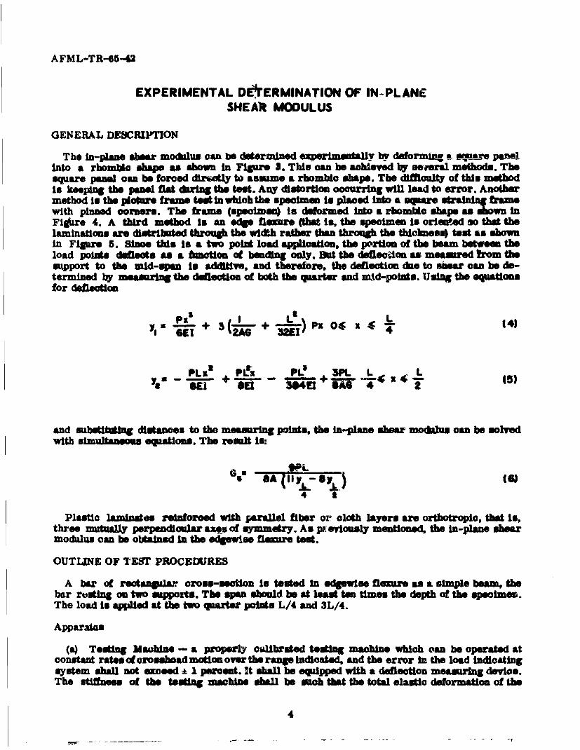
The in-plane abear modulus can be datermlned oexpermently by dafornm a @quaa". pa-nnAinto a rhombic shape as shown in Figure 3. This can be achieved by several methods. Thesquare panel can be forced dir•atly to assume a rbombic shape. The difficulty of this methodis keeping the panel fat dring the test. Any distortion occurring will lead to error. Anothermethod in the pioture frame test in which the specimen is placed into a sqnare strining frawmwith pinned corners. The frame (spelmoe) is deformed into a rbombio shape as shown InFigbre 4. A third method In an edge flexure (tht is, the specimen Is orieated so that thelaminations are distributed through the width rather than through the thickness) test as shownin Figure 5. 8inos this is a two point load applcation, the portion of the beam between theload points deflects a a hunctton of bending only. But tho defloedon as measured bom thesupport to the mid-span is additive, and therefore, the deflection due to shear can be de-termined by measuring the defectlon of both the quarter and mid-points. Using the equationsfor deflection
Pi L a4 L6-9 -+ 3(ke- + PbK 041 x (4)
PLn e PO 3P1. L 4
ySe R1 -a 3w 4E1 UA T 4 2
and substituting distances to the measuring points, the in-plane shear modulus can be solvedwith simultaneous equations. The result is:
6' SA (11 a3.F-Sv34 t
Plastic laminates reinforced with parallel fiber or cloth layers are orthotropic, that is,three mu•ually parpendioular &axs of symmetry. As p•'eviously mentioned, the in-plane sbermodulus can be obtaiued In the edgewise flnexure test.
OUTLINE OF TEST PROCEDURES
A bar of rectanlar oross-section is tested in edgswlee flexure as a simple beam, thebar resting on two supports. The span should be at least ten times the depth of the speoLmeu.The load Is ap&Wied at the two quartar points L/4 and 3L/4.
Apparatus
(a) Testing Macbine - a properly calibrated testing machine which can be operated atconstant rate of orosahoad motion over the range indicated, and the error In the load indicatingsystem shall not seooed * I percent. It shall be equipped with a delection measuring device.The stiffness of the testing machine ehell be mbh that the total elastic deformation of the
4

AFML-1_R-65-42
p1flff 9 /Ifff, r /14 f jff
Figure 3. Forcing Square Panel Into Rhombic
p
Figure 4. Picture Frame Test
p p
pp "YL y
Figure 5. Quarter Point Edgewise Flexure
5

AFML-TR-65-42
system does not exceed 1 percent of the 6DtW deflection of the test specimen dihrng test orappropriate oorrections shall be made. The load indlcating mechanism shall be essentiallyfree from Inertia lag at the crosehead rate used.
(b) Loading Nose and Supports - the loading no.. and supports shall have cylindricalsufacea. In order to avoid excessive Indentation. the zadius of the nose and supports shall beat leas 3_2 m-m (ll1/8 in, fo k& all peoimense
Test Specimens
The specimens may be cut from, shedts, plates, or molded shapes, or may be molded to thedesired finished dimensions.
For Materials 1.6 mmv (1/16 In.) or Greater In Thickness - for edgewise tests the widthof the specimen shall be the thickness of the sheet and the depth shall not exoeed the width(Notes 1 and 2*). For all tests the aspac shall be at least 10 times the depth of the beam. Thbespecimen shall be long emough to allow for overhanging on each end of at leasd 10 percent ofthe span bid in no case less than 6.4 mmn (1/4 in.) on each end. Overhafg shall be sMafloentto provedt the specimen from s@Upping througha the supports.
Number of Test Specimens
(a) At least five speclmons shall be tested for each sample in the case of isotropic ma-terials or molded specimens.
(b) For each sample of animotropic material in sheet form, at least five spocimens shallbe tested for each condition. Recommended conditions are flatwise and edgewise tests on~specimens cut In lengthwise and crosswise directions of the sheet. For purposes of this test,a'length~eaeO shall designate the principle axis of anisotropy, and shall be Interpreted tomean Lixe direction of the sheet known to be the stronger In flexure. OCrosswise' shall be thesheet direction known to be the weaker inflexure, and shall be at 90 dmerea to the legthwisedirection.
Conditioning Test Specimens
Unless otherwise indicated In Material Specifications, all test specimens shall be con-ditioned In accordance with Procedere A described In Section 4(s) of the Methods of Con(tcnIng Plastics and Electrical Insulating Materials for Testing (ASTM Designation; D 618) , andtests shall be oondaote In the Stanahrd Laboratory Atmosphere as defined in th amspecification.
*Noits 1 - Whenever possible, the original mar acse of the sheet shall be unaltered. However,where machine limitations make tt Impossible to follow the above criterion on the unalteredsheet, both surfaces shall be machined to the desired dimensions and the location of the speci-mnans with reference to the total thickness shell be noted. The values obtained on specimenswith machined varfaces may differ from those obtained on specimens with original surfaces.Consequently, any specifications for fLexural properties on the thicker sheets must statewheher the original inarfaes are to be retained or not.
*Note 2 - Edgewise tests are not applicable for sheeds that are so thin that specimensnteeting these requ-rmena cannot be cut. If specimen depth eoceds& the width, bucklingnay occur.
6

AFML-TR-65-420
Procedure
(a) Use an untested specimen for each measurement. Measure the width ard thicknessof the specimen to the nearest 0.03 mm (0.001 in.) at the center of the span. For specimensleos than 2.54 mm (0.100 in.) in thickness, measure the thickness to the nearest 0.003 mm(0.0001 inl.
(b) Determine the span to be used as described in Section 5. After the span is set,measure the actual span lengtb to the nearest 1 percent.
(c) Where Table 1 is used, set the machbir for the specific rate of crosahead motion, oras near as possible to it.
(co Align the loading nose and supports so that the axes of the cylindrical surfaces areparallel and the loading nose is midway between the supports. This parallelism may bechecked by means of a plate with parallel grooves into which the loading nose and supportsWill fit when properly aligned. Center the specimen on the supports, with the long axis ofthe specimen perpendicular to the loading noses and supports.
(e) Apply the load to the specimen at the specified crosshead rate, and take simultaneousload-denlection data. Deflection shall be measured either by gages under the specimen incontact with it at the center of the span, and at one quarter point, the gages being mountedstatilonary relative to the specimen support, or by measurement of the motion of the loadingnose relative to the supports with a gage at mid-span. In either case, appropriate correctionsfor indentation in the specimens and deflections in the weighing system of the machine shallbe made. Load-deflection curves may be plotted to determine shear modulus,
TABLE 1
SUGGESTED DIMENSIONS FOR TEST SPECIMENS
i - I L E ."
Nominal Width of Length of Test Span, Rate of Cross-Specimen Specimen, Specimen, mm (in.) head MotionThickness, mm (in.) ' mm (in.) mm (in.) permm (in.) min.
0.8 (1/32) 25.4 (1) 50.8 (2) 15.9 (5/8) 0. 51 (0.02)1.6 (1/16) 25.4 (1) 50.8 (2) 25.4 (1) 0.76 (0.03)2.4 (3/11) 25.4 (1) 63.5 (2 1/2) 3b.I (11/2) 1.02 (0.04)3.2 (1/8) 25.4 (1) 76.2 (3) 50.8 (2) 1.27 (0.05)4.8 (3/16) 12.7 (1/2) 102 (4) 76.2 (3) 2.03 (0.08)6.4 (1/4) 12.7 (1/2) 127 (5) 102 (4) 2.79 (0.11)9.6 (3/8) 12.7 (1/2) 191 (7 1/2) 152 (6) 4.06 (0.16)
12.7 (1/2) 12.7 (1/2) 254 (10) 203(8) 5.33 (0.21)19.1 (3/4) 19.1 (3/4) 381 (15) 305 (12) 8.13 (0.32)25.4 (1) 25.4 (1) 495 (19 1/2) 406 (16) 10.92 (0.43)
7

AFML-TR-65-42
Rotests
Values for properties of shear modulus shall not be calculated for any specimen thatbreaks or bookes at some obvious, fortuitous flaw, unless moh flaws consttet a variablebeing studied. Retest@ shall be made for any specimms on which values are not calculated.
Caloulstion of Ohar M odelu
A beam is tested In edgewise fleure as a simple beam supported at two points and loadedat the quarter points. The shear modulus in the plane of the panel can be calculated with thefolowing equation.
9PL$A (1P3F- yL) 17)
T I
wbere.
G - In-Plano shear modulus
YL/4 = dalcotion at the quarter point in millimeters (inches)
YL/2 - duflection at mid-span
Note that this equation is based on tho difference between two defleotions. Time eztromecare must be eurlcsed in malng these meamuremente or the reslts will not be aocurate.
A - bd, the cross sectional area in square centimeters (square inches)
P - load at a given point on the load deflectiea curve, In kilograms (pounds)
L - span, in oentimeters (inches)
b - width of beam tested, In centimeters (inches) and
d - depth of beam tested. In oent/meters (inches)
Arithmetic Mean - for each series of tests, the arithmeLo mean of all values obtainedshall be oalculated to three sisifloant figures aL'nd reported as the aiverage value" for theparticular property in question.
Standard Deviation - the standard deviation (eotlmats4 shall be calculated as follows andropored to two sipificant figures:
9 -I
8 ,

AFML-TR-65-42
where:
S - eatimated standard deviation
X - value of single observatlon
n_ - nmbar of obaervtilons
X - arithmetlo moan of the set of observations
Report - the report shall Include the following
(1) Complete Idmmtifloation of the material tested, Including type, source, mainufact•rer'scode number, form, principal dimensions, and previous history,
(2) Direotiono of cutting and loading specimens,
(3) Condttionir. proceduse,
(4) Depth and width of the specimen,
(5) Span lenth,
(6) Span to depra ratio,
(7) Radius of sapports and loading nose,
(8) Rate of croashead motion In millimeters (inch"q per minute,
(M) Maximum strain in the outer fiber of the specimen,
(10) Shear modnlus, average and standard deviation.
The above oc~ins is bamod on ASTM Desigpalon: D 790-63. mStandard Method of Test forF r't PrOpu--- of plPg-Wafts,3 and Milt Sandard 401A, 4Sandwioh Constructions andCore Meterials; Umwral Test Methods.0

A FML-TR-65-42
FOUR POINT LOADING TEST
GEN ERAL DESC RIPTTON
The saddle test or four point loading in useful in determining one of the three possibleshear moduli, where with the torsion test of rectangular beams, the effects of two of thethr•e moduIli are combi"ned. In thhe saddle test, the shear modulus, G, is measured by imposinga pure twisting moment on a square plate. This is accomplished by plncing four equal forcesat the corners of the square plate. The forces are perpendicular to the plate with those forcesat the first and third (diagonal) corners being upward and the other two forces downward. Thecorner loads force the square plate to assume a hyperbolic paraboloid or a saddle shapedsurface. The sections of the surface made by vertical planes through the diagonals are twoidentical parabolas, one concave upward and the other concave downward, with the verticesat the center of the plate.
The shear modulus, G, can be computedfromthe ratio of the imposed loads and the verticaldeflections of the plate with respect to the center of the plate under test. The derivation ofthe following equation is found in Appendix MI.
Sf 3Px yI~
(9)Wts
where:
P - the load applied at each corner (lt)
t - plate thickness (in)
w = deflection of a point (xy) on the diagonal with respect to the center of the plate (in)
(xy) - coordinates of the point on the diagonal (in) (See Figure 16)
G - shear modaluo with respect to the plane of the plate (psi)
The equation becomes:
G X 3Put
where:
u - the diagonal distance from the center to point (x,y)
To insure correct test results the following steps are necessary:
(1) Never exceed one-half the proportional limit of the material.
(2) It is recommended not to lot u exceed half the distance from the center to the cornerof the plate, thus amoiding any localized loading conditions at the corners of the plate.
10

A FML-TR-65-42
(3) Since both the testing machine and the indicated deflection are twice the actual load ateoch corner and the deflections of one point with respect to the center, the indicated values m sybe substituted for P and w.
When possible, fairly thick specimens should be used in order to avoid effects associatedwith initial curvature. The side to thickness ratio should be maintained between 25:1 and 50: 1.If any initial curvature is present, it can be minimized by obtaining two load-doflection curves,one with two given corners deflected downward and the second curve with these cornersdefle ted upward. If there is a large difference in the two calculated shear moduli because ofa deflection which is too large or lack of symmetry in their lay-up, the average of the modulicannot be accepted as a good value of the actual shear modulus. In order to apply this test toorthotropio materials, the orthotropic axis must be parallel to the sides of the specimen(See Appendix HI).
If the plate to deflecting according to theory, then lines drawn on the faces of the squaretest specimen, parallel to the edges, must remain straight during the experiment. A straightedge may be used to determine whether gross departures from the theoretical assumptionsexist in any given plate. Also, the deflections of the four gage points with respect to the centershould be approximately equal.
The shear modulus fixture is shown in Figure 6.
As mentioned before, localized loading effects may exist at the corners. To avoid this, thesharp loading points found in the fixture (Reference 1) may be replaced with roller bearings(micrometer ball attachments). The use of roller bearings at the loading points allows theplate to shift its points of contact as deflection occurs. The rounded surface also distributesforce better than a pointed support which may indent the test plate. This indentation maycause separation of the fibers of a reinforced specimen as the load increases.
In order to eliminate reader error when recordingload verses deflection, the dial indicatormay be replaced with a microformer which allowsuse of the x-y recorder. This newer methodmay be necessary when testing low modulus materials, where the rate of deflection to loadapproaches the 0.3"/min crosshead speed.
OUTLINE OF EXPERIMENTAL PROCEDURES
Direction of Grain - the orthotropic axis of the laminate shall be parallel and perpendicularto the edges of the test specimen.
Test Specimen - the test specimen shall be square, with the thickness equal to the thicknessof the material and the length andwidth not less than 25 nor more than 40 times the thickness.The thickness, length, and width of each specimen shall be measured to an accuracy of not lessthan : 0.3 percent. Care shall betakento avoid obtaining test specimens with initial curvature.
Loading Procedure - the test specimen shall be supported on rounded supports having aradius of curvature not greater than one-half in. (6 mm) on opposite ends of a plate diagonal,and loaded in a similar manner on the opposite ends of the other diagonal. The loading andsupporting frame shall be rigid. Figure 6 indicates the method of test and shows details of theplate shear on four point loading apparatus. The load shall be applied with a continuous anduniform motion of the plate corners to avoid the load and reaction effects. The plate shall notbe stressed beyond its elastic range, and increments of load shall be chosen so that not lesthan 12 and preferable 15 load-deformation readings are taken.
To eliminate the effects of light initial curvature, two sets of data shall be obtained, thesecond set with the panel rotated 90 degrees about an axis through the center of the plate and
11

A FML-TR-65-42
12

A FML-TR-65-42
perpendicular to the plane of the plies. The two results shall be averaged to obtain the shearmovable head at a rate of .003 times the length of the plate in inches (cm), expressed ininches (am) per minute, with a permidlibwe variation ofi 25 percent.
Deformation Measurements - the deformation shall be measured to the nearest 0.001 in.(0.02 mm) at two points on each diagonal equidistant from the center of the plate. Thesemeasurements preferably shall be made at the quarter point of the diagonals, and if otherpoints than these are chosen, care shall be taken to avoid location near the modulus for theplate. A satisfactory arrangement for measuring relative deformation is indicated in Figure 5.
Calculation - the shearing modulus of elasticity shall be calculated as follows:
2t w
where:
G - shearing modulus in pe ,ods per square inch (kg per sq. cm)
P - load applied by the test machine to the panel. (This inad is twice that applied to eachcorner) in pounds frt
t = thickness of the plate in inches, (cm)
w = deflection as read on the dial gage (twice the deflection relati7e to the center) in inches(cm) (Note 3*)
u - distance from the center of the panel to the point where the deflection is measured ininches (one)
The above is based an ASTM Standards for the determination of plate shear.
*Note 3 - The average valuee of panel w are generally taken from the slope of a previouslyplotted load-daflection curve.
13
A FML-TR-65-42
TORSION TEST
GENERAL DESCRIPTION
When a spenimon is suaceratd io toroluorl, a oo-aple normal to UAW axis of the meam~tr is,developed in every cross-ssetion. The formulas for circular shafts of constant cross-sections
are:
I = -T$-ii
G z (12)
These equations are based on the following assumptions: The resultant of external forces Isa couple in the plans perpendicular to the axis of the shaft and these forces are in equilibrium.The specimen is of constant cross-section and during the test the axis remains straight.Planes normal to the axis remain plane and the diameter in any plane remains straight, thatIs, no warping occurs durinn the test.
The material must be homogeneous and Isotropic. The stress must not exceed the propor-tional limit. While Equations (11) and (12) areused to obtain the torsional modulus of rupture,this value Is not the true stress but rather a measure of the relative strengths of variousmaterials.
The ordinary torsion formulas do not apply to a shaft having a cross-section other thancircular. There are several disadvantages associated with nonoircular cross-sections. St.Venant found that plane sections do not remain plane when subjected to torsion. As previouslymentioned in the saddle shear test, three different principal shearing moduli are possible.These shearing stresses correspond to the shearing strains of the three planes of elasticsymmetry. In the torsion test of non-circular cross-seectiQns, these mou il h ave the combinedeffect of two of the three modui.In order to obtain either modulus, it is necessary to combineresults of teats on two or more specimans having different dimensions.
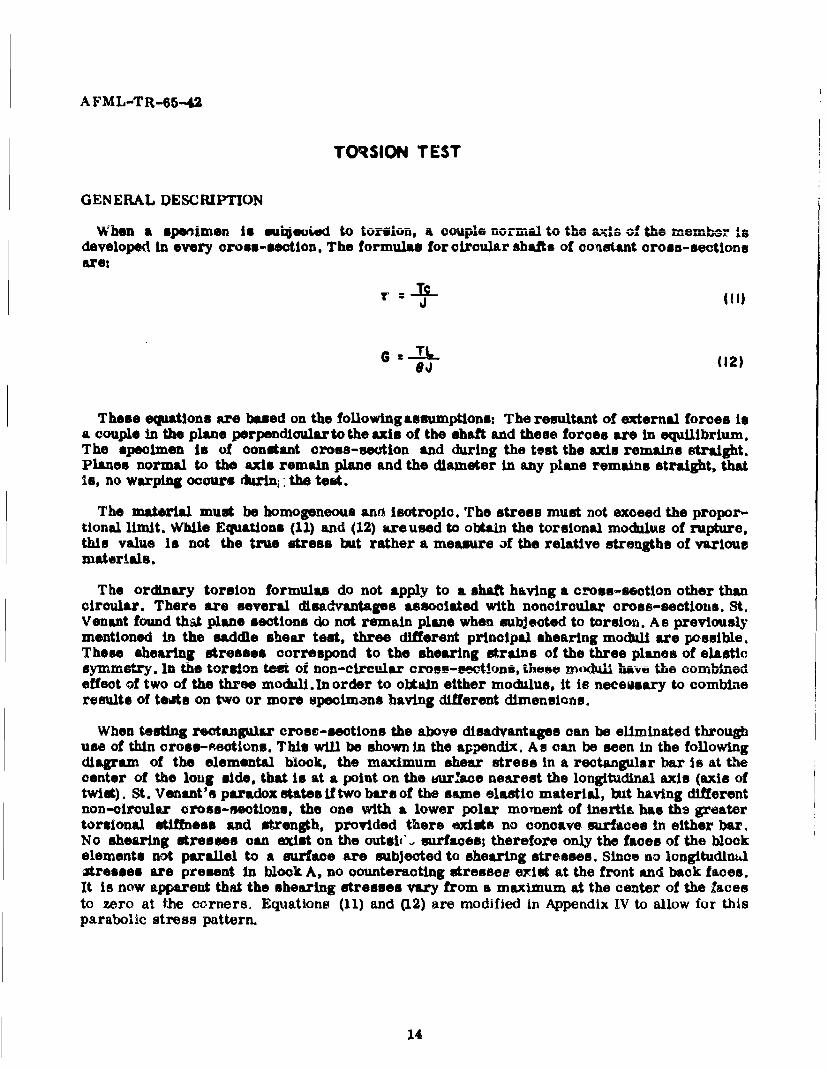
When testing rectangular cross-sections the above disadvantages can be eliminated throughuse of thin cross-sections. This will be shown in the appendix. As can be seen in the followingdiagram of the elemental block, the maximum shear stress in a rectangular bar is at thecenter of the long side, that is at a point on the &unrlace nearest the longitudinal axis (axis oftwist). St. Venant's paradox states if two bars of the same elastic material, but having differentnon-circular cross-sections, the one with a lower polar moment of inertin has the greatertorsional stiffness and strength, provided there exists no concave surfaces in either bar.No shearing stresses can exist on the outsiC, surfaces; therefore only the faces of the blockelements not parallel to a surface are subjected to shearing stresses. Since no lcngitudinulatresses are present In block A, no counteracting stresses erist at the front and back faces.It is now apparent that the shearing stresses vary from a maximum at the center of the Zacesto zero at the corners. Equations (11) and (12) are modified in Appendix IV to allow for thisparabolic stress pattern.
14

A FML-TR-65-42
AssumedVoration
A-- INYI 2
Figure 7. Torsion Member with Elemental Blocks
OUTLINE OF EXPERIMENTAL PROCEDURES
This method describes a procedure for determining the stiffness characteristics oflaminated plastics by direct measurement o0 the apparent modulus of rigidity.
Significance - the property actually measured by this method is the apparent modulus ofrigidity, G, sometimes called the appareot shear modulus of elasticity. It is important to notethat this property ts not the same as the modulus of elasticity, E, measured in tension, flexure,or compression. The measured modulus of rigidity is termed "apparent* since it is the valueobtained by measuring the angular deflection occurring when the specimen is subjected to anapplied torque. Since the specimen may be deflected beyond its elastic limit the calculatedvalue may not represent the true modulus of rigidity within the elastic limit of the material.In addition, the value obtained by this methodwill also be affected by the creep characteristicsof the material, since the time of load application is arbitrarily fixed.
Apparatus
(a) The testing machine must be capable of exerting a torque of approximately 0.12 to1.2 Kg-cm (0.1 to 1.0 lb-in ) on a test specimen with a span of 38.1 mm (1.5 In ). A schematicdiagram of a machine suitable for this test is shown in Figure 8. The amount of torque maybe varied to suit the stiffness of the test specimen. Different weights should be available forthis purpose. The actual amount of torque being applied by any given combination of weights,torque wheel radii, and shaft bearings shall be determined by calibraon.
(b) Timer - a timer accurate to 0.1 sec.
(o) Micrometer - a dead-weight dial type micrometer capable of measuring thicknessesaccurately to 0.0025 mm (0.0001 iný.
15

AFML-TR-65-U
LOAD CORD
TORQUE- PULLEY STOP PINSCALE GRADUATED0-3601
TORQUE PULLEY
PULLEY
BERINGS-<1 1LOAD
SUPPORT-RODSPECIMEN CLAMP SPAN
TEST SPECIMEN
Figure 8. Torsion Tester
16
AFML-TR-65-42
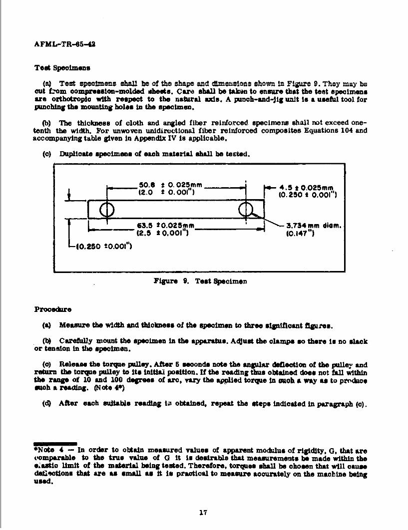
Test Specimens
imlf 'Iwa wjm,.aAr. . a k.ai 11 1w v,E i. ka. ... A ,Uw.. • l ~•.i4 w k*vw. •i 4 C-lp~~b er. j .. U
out from compression-molded dhests. Care shall be takWn to ensure that the test specimensare orthotropio with respect to the natural axis. A punch-and-Jig unit is a useful tool forpunching the mounting holes in the specimen.
(b) The thickness of cloth and angled fiber reinforced specimens shall not exceed one-tenth the width. For unwoven unidirectional fiber reinforced composites Equations 104 andaccompanying table given in Appendix IV is applicable.
(c) Duplicate specimens of each material shall be tested.
am - 50.8 t 0.1025mm 1;
(2.0 t 0. 001) 45t 0,025mmi(0. 250 t0.001 )
*0.025mm a 3.734mm diem.(2.5 * 0.001) (0.147 0)
-10.25 t0."001
Figure 9. Test Specimen
Procedure
(a) Measure the width and thickness of the specimen to three silpafloant figures.
(b) Carefully mount the specimen in the apparatus. Adjust the clamps so there is no slackor tension in the specimen.
(c) Release the torque pulley. After 5 seconds note the angular deflection of the pulley andreturn the torque pulley to its inital• position. If the reading thus obtained does not fall withinthe range of 10 and 100 degrees of arc, vary the applied torque In ouch a way as to produoesuch a reading. (Note 4*)
(d) After each suitable reading ia obtained, repeat the steps indicated in paragraph (c).
*Note 4 - In order to obtain measured values of apparent modulus of rigidity, G, that aretoomparable to the true value of G it is desirabla that measurements be made within theeCatic limit of the material being tested. Therefore, torques shall be chosen that will causedoe±lctions that are as small as it is practical to measure accurately on the macbine beingused.
17

AFML-TR-65-42
CaLlcula~tion
(a) Calaulate the apparent modulus of rigtity, G, as follows
w. (13)wtGS
wheret
T - Torque
w - Width (W21Ot)
t - Thioliemo
6 - Angle of twist
The above tevt are based on ASTM Designation D 1043-61T -Tentative Method of Test forNon-Rigid Plastics as . Function of Temperature by Means of a Torsion Test.M
18
AFML-TR-65-42
REFERENCES
1. F. B. Seely and J. 0. Smith, AdvancedMechanics of Matertals, John Wiley and Sons, 1957.
2. S. Timoshenko and J. N. Goodier, Theory of Elasticity, McGraw-Hill, 1951.
3. H. W. March, E. W. Kuenzi, and W. J. Kommers, 'Method of Measuring the ShearingModuli in Wood," Forest Products Laboratory, Department of Agriculture, Report No. 1301.
4. G. Murphy. Advanced Mechanics of Materials, McGraw-Hill, 1946.
5. S. TimoshonkD andG. H. MacCullough, Elements ofStreng!t of Materials, D. Van NostrandCo., Inc., 1949.
6. E.C.D. Erickson and C.B. Norris, "Tensile Properties of Glass-Fabric Laminates withLaminations Oriented in Any Way," Forest Products Laboratoryg, Deparent of AgricultureReport No. 1853, November, 1955.
7. A.G.H. Diets, Engineering Laminates, John Wiley and Sons, 1949.
8. E.E. Seohler, Elasticity in Engineering, John Wiley and Sons, 1952.
9. A.E.H. Love, A Treatise on the Mathematical Theory of Elasticity, Fourth Edition,Dover, 1944.
10. R. V. Southwell, An Introduction to the Theory of Elasticity, Oxfurd, 1936.
11. S. Timoshenko, Strength of Materials Part I Elementary Theor and Problems, D. VanNostrand, Inc., Third Edition, 1955.
12. S. Timoshenko, Theory of Plates and SheUs, Second Edition, McGraw-Hill, 1959.
13. A.E. Taylor, Advanced Calculus, Ginn and Co., 1958.
19

AFML-TR-45-42
APPENDIX I
DERIVATION OF ORTHOTROPIC SHEAR MODULUS EQUATION
In order to derive an equation for this shear modhus of a two dimensional orthotroptcmaterial as a function of Young's modulus of elasticity and Poimson's Ratio. we start by
Poreoalling the gmnertllad equations of Hookian behavior for two dimensional Wnisotropy.
4x ii xu t yy a uy 114)
4yy a0# O'xx +- all 'yy+ 0ssrxy (15)
y :+ %so, + aKy a, asl 116
If we oonsider an orthotropic material whose elastic constants, parallel and perpendicularto the natural axes, may be measured, then, we may obtain stress-strain relations fororthotropic plates.
y
S~Figure 10. Axis System for Composite
S~In the system. shown (Filpe 10), the equations become-
GoI O'i, Pm O'n or ' i 8
!~E# E~l[t ll Ell(lO
42t2 Et E! 419)
21
I 2•
I

AFML-TR-65-42
The laws of elaeticity are known in directions 1 and 2 but not in the x and y direction. Wedesire to know tne stresses as referred to a set of axes x and y which make an angle 9 withthe natural axes. I and 2. Transformation a•,•latio a for stroas And at-rAn 00- be derivedfrom purely geometrical considerations for this new axis.
The following ann1yo~s derves the needed equations:
Conalder a two-:bmensiond element (Figure 11) subjected to a general stress field,
I - Y y
TRY
%y
Figure 11. Two-Dimensional Element
If the stress distribution is known with respect to a given coordinate axis, then it can be
determined with respect to any other coordinate axis by means of transformation equations.
So then consider an element of unit thickness with one face of unit length perpendicular to
the 1 axis. AUl elements of a body in equilibrium are thexrselves in equilibrium If all external
and internal forces are considered.
2
TII
'0'XX C. .
Figure 12. Stressed Orientation for Element
22

AFML-TR-65-42
Summing forces in the 1 direction (Figure 12):
a-,, - O' 1cos•cosO - .,y sin~cos6-
cyr sinesin 8 - r,, cos8sintf 0
or
"Oil 7. Oxcos8O + Csyysin" + 2 r., sint, zos6 (20)
Similarly, considering an element with face perpendicular to the 2 Wexs:
Y
2
fyY
Figure 13. Stressed Orientt•ton for Element
Summrirng forces in the 2 direction (Figure 13):
c,- " x. sinO sinO + Txy cos0 sinO
- all Cos cos8 + XY sinecos6 a 0
or
Oja z vX. sineG + cyyos'6 - 2 ry sin cose (21)
Then summing forces on either element:
r, + ay. sin~cos6- rxycos~cosO
- ayy cos~sinO + ry sin~sini? = 0
23
AFML-TR-65-42
or- "l " --- •- I.f 'Sl d", , -a ...
rigugw- ShIfUCOOV + T 1 U -Sin V a,2at •yy I~uo X sn •, + x
Summarily,
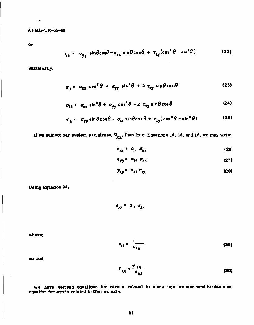
c r cos°e + c"yy singe + 2 r.,y sin cosO (23)
*g2 cr, singe + a- Yc0ll' - 2 T(y sinecose 124)
rim x OyyuSin oS6 - CU sinecose + ;xy(COs6-since) (25)
If we subjeot our system to a stress, Cy , then from Equations 14, 15, and 16, we may write
*xx Q , o xx (26)
cyy O Gl@ 55xx (27)
YX" a85xx (28)
Using Equation 23:
fXx x 4 11 Oxx
where:
all " "-"129)I;X
so that aota.
E z-xx Exx (30)
We have derived equations for stress related to a new axis, we now need to obtaln anequation for strain related to the new axis.
24

A FML-TR-65-42
To set up strain equations at a point in a deformed body, conslder a small length r alongthe 1 axis.
y
I
Figure 14. Axis for Strained Orientation
The projections of this length on the x and y axis are:
Ax r cos 8 131)
'Ay r $in (32)
If you and v are displacements of the point A, the displacements of the point B can ýaexpressed,,
axy
V V + A- + y (34)
After deormation, the coordinates of point B, which were origLna1ly x and y become:
Ax +u -u: Ax + - &t + (u (35)Ox d, av a
Ay + v- z v Ay + - AX + -L &Y (36)
The new length of r after elongation becomes r + C r, therefore:
Ir + e) (2 + + au &
e a
25

A FML-TR-65-42
Dividing by r and substituting for x and y
(i + 4) z [co06(i + +1-v) + sine
+ [Co0111 + f;in (i+ ,)
Since ( and derivativesdu du av dv
T- WIax-
are small quantities, all orders higher than the first may be neglected.
Expand and neglect higher order terms:
I + 2c cosZ1 + 2 cos 2 -A- + 2 sine cos8 duax d
+ sinOI + 2 sin6 --. + 2 sine cosO a.vax
Then the unit strain through a unit area along AB becomes:
E1 cos Am + sine cose & + s;n't 8:E If = Coscos ORy dy
+ sincose -3"dK ( 38)
And aince by the classical strain-displacemont relations:
- u{xi =X du- (39)
dv4 yy J - (40)
the , x c+ y (41)
then
4F RXCoste + y sin'8 + yxy sin~cos8 (42)
and conversely,
26

A FM L-TR-65-42
Ex 'e1 coi'6 + C., sin'O + y,, zin~cos8 (43)
Then using Equation 30
and substituting Equation 43
1 4 OS~ + '911 si"e +-YosinecosG]-rx ~ I IF
and from Equation 43
-I = ______ !!i,8 sin 21
+ -ý' sin~cosi9
By using Eq'iations 17, 18, and 19,
1~ a = ~ -! [-L-ss O' osg - /AI ax min6e
+ ~ ~ _______ siM,, fi oýLto e "XCOS'6 in*
-Cos 48 2 ýLl sin3 9cose uin4B cos Gsin'O
+ E-f + (44)
Solving for G 12 yields-
SCou'Gsino8I ~ siB1 ___ICO$
4 -- 2 ju. vi#n~cos"'a I I45)Ex 4EII Ell I a
2?

A FM L-TR-65-42
When 6 48"
s Is0s : Gas : 14 I L {_2I A,.
E4; Eat2 E4
28

A FML-TR-65-42
APPENDIX II
CALCULATION OF SHEAR MODULUS OF A FIBERREINFORCED COMPOSITE FROM THE DEFLECTIONOF A QUARTER-POINT SYMMETRICALLY LOADED
BEAM WITH A RECTANGULAR CROSS-SECTION
The effect of shearing force on the deflection of a beam has been discussed by Tlmoshenic(Reference 11). He shows that the slope of the deflection curve due to sheir is equal to theshearing strain. Thus
dy r. ___yo VO (47)dx G JWG
wheres
Ys - deflection of beam due to shear
V = shear force
Q = first moment of area about the neutral axis
I - moment of inertia
w - width of the beam at y - 0 (this is assuming the neutral axs is located at y - 0).
Assuming small deflections, the equation for curvature of the deflected curve consideringboth shear and bending is
daY days dtyb M + Q dVd y + a: El 1W -- (48)
dxt dxt dx E iW dx
where:
Yb - deflection due to bending as obtained from the Euler-Bernoulli law.
Looking at Figure 15 we see a simply supported fiber reinforced beam loaded with a forceP at x - L/4 and at x SL/4. Since only the normal stress 7xx and the shear stress 'r XY are
considered, simple beam theory will still apply to the case of an orthotropic material.
For a beam of rectangular cross-sutiton
awdt wds
where d - depth of the beam. Equation 47 becomes
29

AFML-TR-65-42
dy$ 3
dx 2 AG
where A, of course, is the cross-seotion area. Using Equation 48 the equation for curvature
will be
d_ , U+ _j dV (49)dx' El 2AG dx
Using this equation forthe section 0 sx T.L/4 along with the shear and moment diagram we have
dKI EI 2AG dx
dy1 PIi 3P
px 3Px+C
I- IE 2AG + c,3
zt 0 , Y:O, A° ©:0
Px3 +- 3PxY, -iE * "2-A- +*c, A
PLPP
PL
4
moment
Figure 15. Simply Supported Fiber Reinforced Composite Beam with Quarter-PointSymmetric Loading Showing Shear and Moment Diagram
30
AFML-TR-65-42
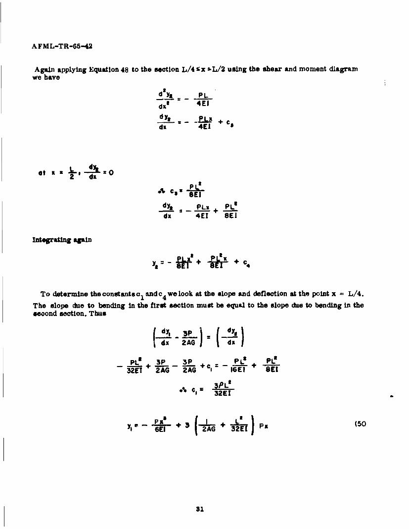
Again applying Equation 48 to the section L/4 'x 5-L/2 using the shear and moment diagramwe have
dl~ PL
dx 4E1dy, • c
dx 4E1
atx dx
.%, c 3 -: '
dy3 2 PLX + PL'
dx 4EI 8E
dx 4EI SCI
Integrating again
yt f--+ P- +c 4
To determine the constants oI and c4 we look at the slope and deflection at the point x = L/4.
The slope due to bending in the first section must be equal to the slope due to bending in theseoond section. Thus
PP(-0xy MA dA'O
P 3P 3P + 0 PO32ES 2AG 2AG : 16E1 + 8EI
*% Cg 3PL'"I c 32E1
-- PX a, . 3 -L + L Px (50
60 ( 2AG~ 32E)(0
31
AFML-TR-65-42
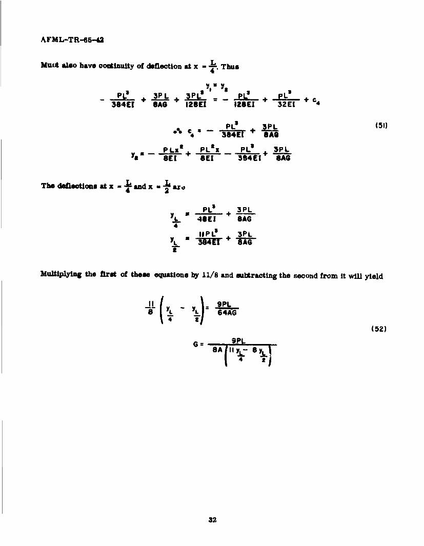
Mutt also have ooninuity of deflection at x Thus4 't
PL! 3 PC + cL' + C384ET sA" 12E(1 IZSEI 32E[ 4
PC % a _PL (51)
PLx + PLax PLI . 3PLYa- SEK SE 3-"4EI+ SAG
The deletio• s at x - and x -" ara42
PL + 3PL
48E1 SAG4
4 IPL+ 3PL
T -Wu reu-
MultiAPYIn the first of these equations by 11/8 and maitracting the second from it will yield
11 YLL 9PLif YL- 64AG
4(52)
G=: 9PL
43
32

A FML-TR-65-42
APPENDIX III
DERIVATION OF PLATE EQUATION FORSADDLE SHEAR TEST
According to St. Venant's princip~le, a square plate loaded with a constant twisting momentalong its edges is statically equivalont to the loading shown in Figure 16, provided the thick-noes of the plate is small in comparison to the other dimensions. For a more detailed Justifica-tion of this statement see Reference ;\2.
y2/ 2M
2MI/ /0_ Pa -71 ,-; 12,
Figure 16. Orthotro)pic Plate Loaded at Corners
1;nv. n,4thnttnnii nlat'an
S(53)
y G-
Let w deflection In z direction of any point point (xy) in the plane of the plate,
-Do (56)
M • +Da v.%) (+,)
33

AFML-TR-65-42
Gf3~5 (58)
where;
Mx - moment per unit length along the edge parallel to the y-axis
My - moment per unit length along the edge parallel to the x-axis.
Mxy W twisting moment per unit length dlstributed along the edges.
DI Exts 3 R EIt
In this particular problem
M 1 M= y 0 ; MXY M,
Using Equation 52
6M,- 6w
Gh 3 Oa
Integrating with respect to x
aw - 6M1
Integrating with respect to y
W =+ ,, y, + f (59)Gts
from Equation 59
0x2-x I
ay4
34

AFML-TR-65-42
Using Equations 56 and 57 with the conditions Mx = a: 0 will yield
fy1it + OA., Y, z 0
; ]+ I" 'x j fit( >
These equations must be 0 for all values of x and yI
0%. fa' (x a C, constant 160)
f," y a C 2: constant (61)
1 #/hY C1 0
I /Lyx C 0
We see the solution to this to c 1 = c 2 = 0. Using Equations 60 and 61:
"(63)0% fit 'C X +C
see f, I yH = ce y +'co 6*
Using Equations 62 and 63 in Equation 68 we have
6MI
w : • xy + C x . c¢ y + C7
whsrI C, i?
wh ere . cT 7 Is a 4 + c 0
Other conditions
35

AFML-TR-65-42
I. w (0,0) 0 066 C 0
2. 0 .-. CS :o
a x I N a 0lyJ -o .0. ,
Now
GM0W 2• xy
Replacing Ml by the tstaticall equitvalent load shown In Figu~re 16 we have
W 3P xy (64)Gtawhore P x 2 M4
If we let u - the diatanoe from the origin along a diagonal of the plate-
U
£Pu (65)
9% W xUZGh-!
*Note 5 - The orthotropic stress-strain relationships are good only when the x and y aidsar both principle axis of symmetry of the orthotropic material. Otherwise Equations 64 and65 will not work.
36

AFML-TR-65-42
APPENDIX IV
TORSION OF AN ORTHOTROPIC BAR
The St. Venant semi-lnvers approach will be used.
•Y
Filgure 17. Par of Arbitrary Cross Section Subjected to Torsion
AssuLme
'Cr.," , yff CrYr zz = rxy"a 0 (66)
Now applying orthotropic stress-strain relationships (assuming x - y axis to be orthotropicaxle of material)
Gxx Txx
-Y E' (o',, - "Y,,, o.,, - ,,,, o-z,)(67)
I €.
"-, " Tz( ~zz -Lz V,,o- - 0.,, -,,,,
31 XYry Y Gyz yZ z - Gas Jz
37

AFML-TR-65-42
we see that
fxx N 4yy =Y 4zz • YXY 0
(XX f,(y,z)
yy ay (68)
z " O----.w & 0Xy)~)u c~vat, af3-~ = a_.• + L V_ a f I o%+ -
xy jy Yx y x
Looking at a cross-section of a bar of arbitrary cross-section we can determine thedisplacements
VI
Figure 18. Cross-Section of Bar Having an Arbitrary Shape and Showing Displacements
P ib a point at an angle e to the x axis and s distance r from the origin. P' Is the same pointafter being rotated through an angle zwhere 0 is the angular twist per unit length. Assuming
the displacements are small we have from Figure 18
u = - r8z sin7 a - Yoz69)
v = rz cos• z J O9
In order to solve an elasticity problem it is necessary to satisfy equilibrium, compatibility,and boundary conditions.

AFML-TR-65-42
Looking first at the equilibrium equations
+ -- ý- + 0+ =Cry Ory
dMy yy yzr + + - = ( 170)
-r., + + -O _ZZ 0ax ,y z
Equations 70 %r1il be satisfied provided
=C Z 0 ----rx 91(,Y (71)Oz
16Z y 0 lryz 9lx~y) (72)
dr Cra + -- = 0 (73)
By using the stress strain relationships, Equations 67, and the strain displacement relation-ships, Equations 68, 71 and 72 are satisfied exactly. Since u and v are continuous functionsthey will satisfy coiPlatibilllfvY
In this approach a stress function 0 (x, y) is used which will satisfy equilibrium. If we picks iuch that
TaZ y (74)
Equation 73 will be satisfied and thus the equilibrium conditions met.
Now looking at the compatibil ty equationsat "xYR at-61 at's yy--- + C'a5
39

AFML-TR-65-42
dya a'z a .y- .+ t76)
OPY ale a'asxz 0- sit + 2 (771
4'60 (/ x ay47asg _ xz xy• + o)
2 - = + -+ -,(78)
a'.",._' o o2r a
ala: Oy dx +80
ia'. a r ~- - a)-ooi4A, al ax a, az
It can be DeeO that SInMS 0 isnot a function of z, Equations 75, 76, 77, and 80 will be satisfied.Using Equationm 78 and 79 along with stress atratn relationships we have
dIXI airdx. * dy /
Using 0 In theme relationships yields
a all# + a, 0
BW ,'Z G 'x a"*' yx' Gu ,y-'- '
40

AFML--TR-65-42
Thus at
- + - - (SI) or a constant
usg the displacemkbts and the streus-strWAi relatloneblPO we hATS
or
rZ.. %a (62)
Lia.. .- i+e (83)
- - - 4.z -8 84
subtracting Equation PA fromi EquatIou 83
1_ am# + - -3-ze
6 a C, it ay a
or
912 + Ze(85)
op I~ ays '
41.
AVML-TR-66-42
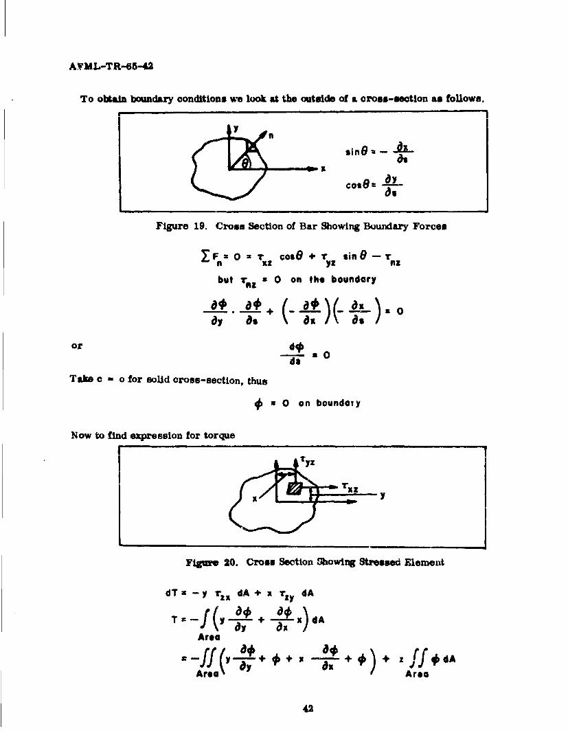
To obtain boundary conditions we look at the outside of a cross-section as follows.
y
sin -
Figure 19. Cross Section of Bar Showing Boundary Forces
Sa- o - r cosO, +r sin 8 -. r
but raz z 0 on the boundary
a0 . a# a0
or
doTake c - o for solid oross-section, thus
* 0 on boundary
Now to find expression for torque
y
Figme 20. Cross Section Showing Stressed Element
dTz--y ri, dA + x rzy dA
T = f (y + _ý X)dA
Area
ff(y -* +#+ z ff #dAArea Area
42
AFML-TR-65-42
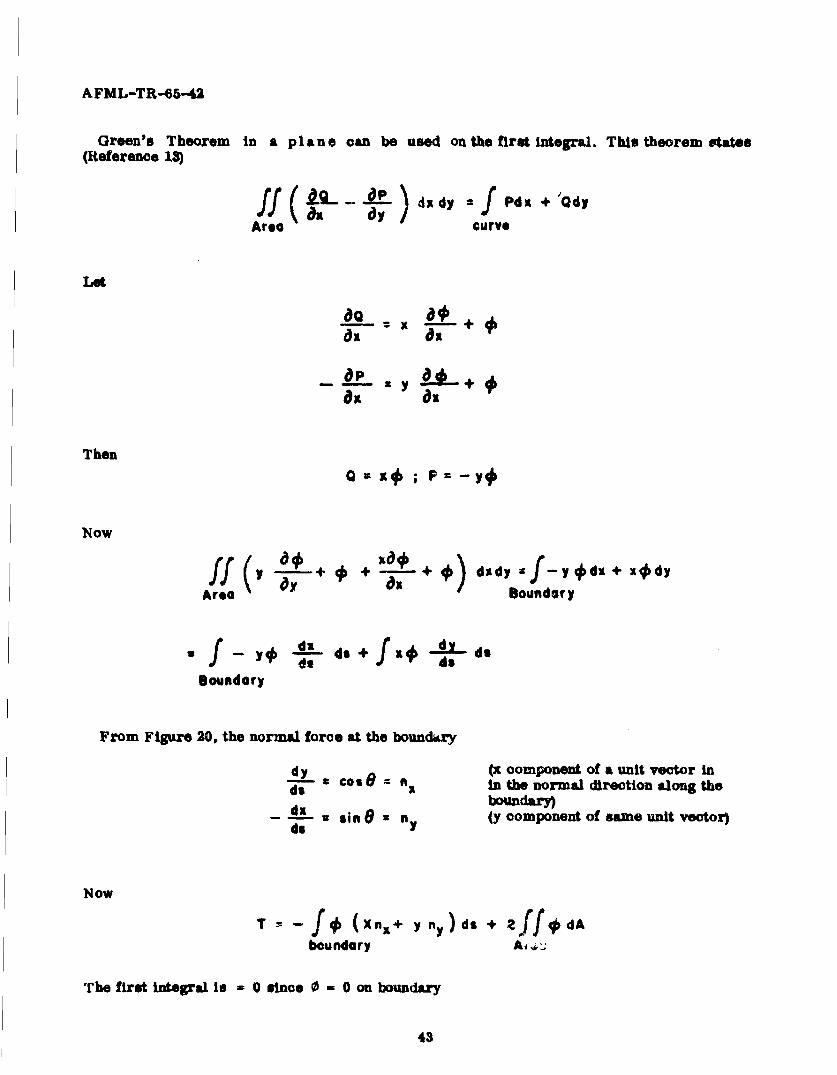
Green's Theorem in a pl a ne can be used on the first integral. This theorem states(Reference 1)
ff ( O-P- d ) d z =f Pdx +'Qd
Area curve
Let
apx y +
Then
Q F1 y#P
Now
S +0 + -+ didy r2j-y~dKt+ j
Area a+ Boundary
do d
Boundary
From Figure 20, the normal force at the boundary
dy Cos 19 =(x component of a unit vector ind� •In the normal direction along the
bound"ry-- d.x sine = ny (y component of same unit vector)do
Now
T -f (Xn+ yn),ds + ,ff 0 , dAboundary A,-,
The first integral Is - 0 since 0 - 0 on boundary
43

AFUL-TR-65-42
T a 2 Jf#dA (86)Area
Figurs 21 shows the crou-mection of an ortbotropic bar subjected to torsion. It wiU beassumed that a/b •i0, which will allow rx. to be nseoeted (Rdereace 2). Thus the stressfmontios 0 will be a famation of y only.
T t
Figure 21. Cross Section of an Orthotropic Bar Subjected to Torsion
Equation 85 will become
!L#-u -- 2 6 (87)
dy
Intagrating Equation 87 yieldis
* -Gxz ay, + C, y + CA
U sing the condition € - 0 at y - •t/2 we have
and
#- 6 - y') e88)
d#a u- u 2 u6 y (89)dy
IVsng ¢quatlon 86 for toz4ue
I wt5 GXZGT f •X 1A• - y- ) dx dy-to
-T
44

AFML-TR-65-42
or
3T (90)wt'9
Let us now look at the cae where the cross-sectiom of a laminate is radially isotropic(that is, GQx - GYd. This is illustrated by the cass of a unidirectional layup of arbitrary
cross-section as shown in Figpre 22.
Figure 22. Unidirectional Composite with Cross Section of Arbitrary Shape
Let the torsional modulus be repremeted by G. Tiros
Gz :Gy :6G
and Equation 8• becoones
t a -v 0
010 0 4K 9- Z0
V ' 00o6 (;
0 K
wh Fisfies t2. Uonidiretiontal Co 0posit wthe Crosnay s in tSsncution of AririySa eld
Thus
V,- -2 G~r 193)
46

AFML-TR-65-42
Tyz = GOr (94)Ty z 3ia
Using Equation 86
T - G ff (r R rd~dr
a-27 f G (r( -Re)rdr
:- VGO (-R' r
Thus
T a (95)2
or
G 2T (96)
The second case we will examine is that of a rectangular bar as shown in Flure 23.
L
Figure 23. Rectangular Cross Section
If 0 ts chosen in this rase by multiplying the equations of the boundaries, the compatibility
condition V 2 0 - 2G q cannot be satisfied. So a nolution will be attempted in terms of a doubleFourier Series
Let
$i Er X I in-nzI M=I m" Wf
46
AFML-TR-65-42
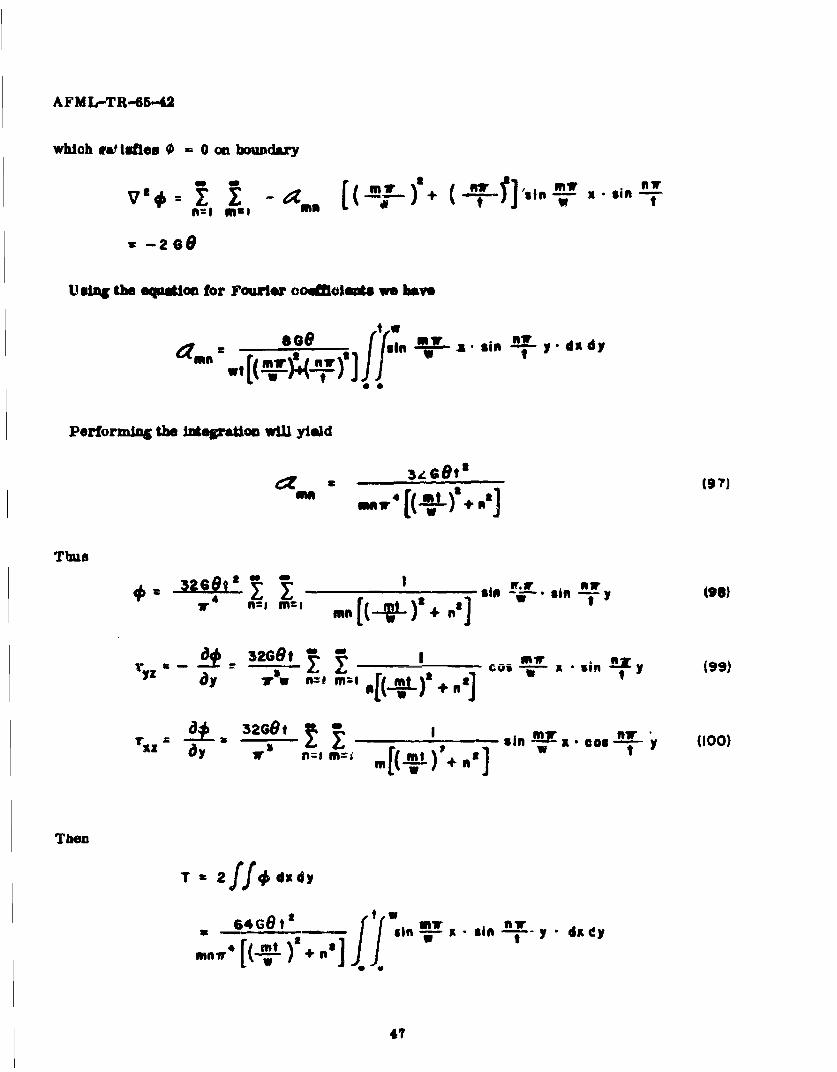
which rat talfes 0 - 0 on bomundary
a - +f] 'Sin x - sin I
3 -268
Using the equation for Fourier coaoflfoemts we bavy
so9 tw L dd
z set? v u--Ia sin ay
a Is
Performing the integation will yield
Sa 3,•,0-t' (97)
Thus
-- r • ,L, CO -* it •,- si y •
4 I m 4 Of SIP~(6
l me [1"r )3 + Mal
Tbun
T " ff/dudy
268t4' t 40
in -i - -y dx G$y
mn,'4 [(xi)'÷.
ThT

AFML-TR-65-42
Let
T 2." CoG tt I2
T (103)
wt
T m1 KOOw t 0.102
K- 2 6 am. I 13
t / IG wt K12
1.5 0.1962.0 0.2292.5 0 .242~3.0 0 .2534.0 0.2816.0 0.299
10.0 0.3120.333
48

UNCLASSI FIEDSeCulity Cas~sificatios
DOCUMENT CONTROL DATA - R&D(4"eiffyi 0044aifjC1tigI of fit*, hod. of abst"te ad it"Id n ME ak~ wmtslm, mus, be Otm d "On As ge 01Ut 1 ov ,-II Iesf a c aedi5~dJ
I ~ ~ ~ ~ ~ ~ ~ ~ ~ ~ ~ g o1un1w A9v' ,~~...au~r .RPORTswCURtiTY C LAUSIP CATION
[ A F I4L (M A N C )
U N C LA S S I F I E DWright-Patterson AFB, Ohio 26 *Ooup
SRIPOR? TITLK
EXPERIMENTAL METHODS FOR DETERMINING SHEAR MOEDULUS OF FIBER REINFORCEDCOMR)SI TE MATERIALS
E'Og9fRqIPTIVII MOT6S (?ypMo aeut #%w n iu.iuivu defts.)
Technical Report :' July_1964 through _December, 1964.S AUTNOR(S) (Los tam. beme fV name. initidla)
Hennessey, J. M.Whitney, James M.Riley, M.S., Capt.2 USAF ______________
C. REPORT DATE ?a. TOTAL6 NO, or PAESK j 76. NO Oir Raew
July 1965 481380, CONTRACT OR SHANT NO. C0 ORIGINA TOR'S REPORT NUMBERA(S)
AFML-TR-65 -42bPRtOJECT NO, 7340Task No. 734003
G. 9*6. STMERJpolrT NO() 001y *a"u tumbe. tat way be assioad
d.
10. A V A IL ABILITY/LIMITATION N@TICU
No limitations
11. SUPPLKIIIENTARY NOTES 12. SPONSORING MILITARY ACTIVITY
AFML( MANC)Wright -Patterson APB, Ohio
1S ABSTRACT
The shear modulus of elasticity of a fiber reinforced is an extremelylimportant mechanical property. The problem of experimentally determiningappropriate shear modulus for orthotropic materials such as fiber reinforcedcomposites is not as simple and straight-forward as in isotropic materials,
4and care must be taken both in the experimental methods and deviation anduse of the appropriate equations.
This report presents four acceptable methods for determining theshear modulus of orthotropic materials. Two methods are appropriate fordetermining in-plane shear modulus and two others are for determining"bending" shear modulus which is applicable in calculating buckling loadsof laminated plates and shells. A discussion of each method precedes themethod of experimental determination. The derivation of all pertinentequations are presented in the appendix for easy reference.
D D 1473 UNCLASSIFI ED_ ___Security Classification

eeiL *leah~M~ a O M a~- .& t.
agv cotw -- -1 ---
I~~~~~~ ~ ~ ~ ~ 09A1AIGIrVT aeytammpm mgrms 111o"b m"I1041 t~L aegs 4~0fl
l~ lowoll, @qAfl4 beeTT bot ", ~
)a 114"93T 5IIC1'T? £LI-WWIATWO -a the .. in1siryi nr~wmwa OsswaweOIta
R.idDoW is *m&mft skv 0 o bo e mco it. Off bp OM oIm. Isimaleag
e~ec ~ p~qS~W~ vthen ~ ftpm Illfwato Swtmm y DO- w goolded ciSGR{ICKV Ambmo dofgg.ili to D.-dw tous DaD UCNmK~E- tkpmmobL
ftw itg have bees wood Owto ealCmW4a pb - -V L4 i maknor agomsel fmil .a~as (*4* ofMa
It- REPORT TTTS.&5m Saw " tciamoin ptipi tube Ow mil alol@4~ hrvl, qp li! wim-tm. T.6w. toa misi shmad be iieabd ___ ________
IS* in muStaut tle Or mm4be silyctiwi~w cs lolttfi~ sy
-w wtt 44 bac wea ~.Iso il" eeam je.
-%, 0 a steetees. ppmoeus toom" mn VURO. H tbe eogm bee.4 #wmab we I.ke Omcr "I Tfm sImkoGwc it~e, 1mcl.w dof U0 a op"Iths reoy Period is Sorwcot..De b.ww Ie Cý1 of cifm ,OtMae t. "m p~mm mk.
WT4c t tue * oft. Iw sad-f umiy p a.v, ad Iswm~
w the tapot. SM40 to atm. owsusar mm.m NW"dIfnOtar) smmor "W swb Immb M *fmya Tite sttteo -w11tv rfw Ola! abw .0ws abowsifi Smalam moP~ IL WWOOK~IM. MUTANTY ACTIVITY fqbe .
00 -dommo petmwl s6tar my IV sawto7 f pwK LPOPT DA~TI $Uom tits 60.. of~ dw qm as ifiry we ) t i'mom as ma ierdepdmin. betS kp eum6
anIbe te-n time &M *1P!ifdl I I &O TWAC - &eaW. an~ asmmwvýI p wat ia iw va *iasmmsmp ofwe dm somM M&, do se.w a# . .wywr epom Orm timslb
Oy 1tTUT&l PINOS3 CW FAGM T. momal c oasi 04 mistyu also alstilom it Oe .wd ad tims abe a.mtot.~tI-II.. maed pe-iim powedgit. ae. v ~abol Symy *A tospt* to ime I says
ýta .Was" OU Ifwow se GRAM 11WSWImid ad U to ll&t d"elo 0 aw of"Osi o (aetolwba aed
a. U.)WnhACT 1GNAN`TNUý doi& fý nW1ys 40w s ~ma 1. upiaau ocipit" resligh t~a, .6 al tlb q1* aw mnewe ale chm l go ms 4w a*"" lbI loubm oO In agu, e.mw4 &a trL ais) toa. it
5 t, a. & a PGJw7T PIMN amos esAy "wsprw womma am am.eiaid knf -rmm )idwsfti t.aras BRamoifiI . -.ild , U Is pas mkwq ~mumbow It
Is twr $11watee tift rftsem tect. a ,wvvel Smdmp be M"4 ofwe toR4AWAT~IC* SXPIS WMIMO "mw ae OM3 w~s 00u',e. Isms ey"%ta .smis .epe s¶ saymmut alos be'0.1 '-v"I musafei 16 aftic ~ us wilaA -09 be whimbu aqi.. 00d "1 910 a. spoWy ft&§*.N*VO.tM 40 PRPIW ~ifits
ap.i .. a Iss obe wigonot o"m~pts Two ?a.obo Ono fim l awal 'as - mm we owPo1bit ems W anw-aIstitt"Ia vepit so Ie off-OWL PPS?- I I a-z m.eagw.Sb-ist sys misty, Ity, mome " e
* .dto mbmm ,ULE1 U Immi. www bm bo"M. '5, -40 Imp in a wet isp sp mew. **" a of IP4owta tremmotaS 01141yof dusew 4mow t omt&O byCro% Pi Tvfm"mo- fIm srw n rtii t *,o
* It. 4%0 wa ssr *~ide a .6*1 tios almo 0 ~ .
m ~ ~ ~ ~ ~ ~ ~ ~ ~ S AVAIL Jtsrv~TAw kv "am wt n
I dmimmsioloammos sas @ Ow upot ýw~b~ dot tst-