search.jsp?r=19690029398 2018-04 … vehicle and propulsion programs division ... translation,...
TRANSCRIPT

https://ntrs.nasa.gov/search.jsp?R=19690029398 2018-06-08T05:03:40+00:00Z

SATIONAL AERONAUTICS AND SPACE ADMINISTRATION Offtce of Space Science and Applications
Launch Vehicle and Propulsion Programs Division Contract NSR 31-001-078
AEROSPACE SYSTEMS and MISSION ANALYSIS RESEARCH
Solar E l e c t r i c Space Mission Analysis
F ina l Report
AMS Report No. 843
Prepared by: 7% &Pi P. M. Lion
Assis tant Professor
M. Handelsman Senior Research S c i e n t i s t
and -,-.
J. P* L o : t Senior Res ;a;r :i Engineer
Approved by: I J. P. i ay toh Research Leader
15 January 1969
Reproduction, t r ans l a t ion , publ icat ion use and disposal i n whole o r i n pa r t by or f o r the United r t a t e s Government is permitted.
Aerospace Systems and Miss ion Andys Ls Rmearch (ASMAR) Program Department of Aeros: i ' e and 1iech:mical Sciences
School of Enginet J ag and Applied Sr ence PRINCET\*rJ UNIVERS TLY

\ \ \ vr asterotd " belt Of
\ \ \
\ Orbit of Earth /
Arrows show Thrust Direction a t 20 day intervals
Optimum Heliocentric Trajectory for a 2 AU Asteroid Rendezvous Using a Solar Electric Propelled Spacecrdft
3 -1 Effect ive Je t Velocity = 5 0 . 0 ~ 1 0 m s
I n i t i a l Acceleration = 5.18x10-~ rn s -2
F l ight Time = 400 days
FRONTISPIECE
- I

iii
SUMMARY
Preliminary mission analyses f o r s o l a r powered, e l e c t r i c rocket
propelled spacecraf t on Mars o r b i t e r , Jup i t e r f lyby and a s t e ro id b e l t explo-
r a t i on , t r a j e c t o r i e s were undertaken wi th in the Aerospace Systems and Mission
Analysis Research (ASMAR) Program a t 2r inceton University.
Mars o r b i t e r t r a j e c t o r i e s i n the years 1971, 1973, 1975, 1977 and
1979 a s analysed by the Hughes A i r c r a f t Company were checked approximately using
an ASMAR modification of the ITEM in te rp lane ta ry t r a j ec to ry computer program.
Another ASMAR computer program, Gordon I, was used t o optimize s o l a r
e l e c t r i c propelled Jup i t e r flyby t r a j e c t o r i e s which iden t i f i ed s eve ra l t r a j e c t o r y
modes and gave an understanding cf the s e n s i t i v i t i e s t o launch vehic le and
propulsion technology.
Preliminary analyses of a s t e ro id b e l t explora t ion missions, e spec i a l l y
rendezvous t r a j e c t o r i e s with advanced technology, ind ica te an i n t e r e s t i n g and
possibly important app l i ca t i on of s o l a r e l e c t r i c propulsion f o r various a s t e ro id ,
planetoid and cometary missions.
ACKNWDGEMENTS
This research was supported froin Headquarters, National Aeronautics
and Space Administration under Contract NSR 31-001-078 during the period 1 Apr i l
1966 through 30 September 1967. M r . J. W. Haughey, Launch Vehicle and Propulsion
Programs Division, Office of Space Science and Applications, and M r . J. Mullin,
E l e c t r i c Propulsion Division, Office of Advanced Research Technology were the
technical monitors. Thanks a r e extended t o them fo r the exce l l en t working
re la t ionsh ips and t o M r . J. W. Stearns , Assis tan t Manager, Propulsion Research
and Advanced Concepts and others a t the J e t Propulsion Laboratory a s w e l l a s t o
a l l o thers associated with the ASMAR Program i n t h i s endeavor.

i v
CONTENTS
TITLE PAGE
FRONTISPIECE
SUMMARY
CONTENTS
FIGURES
TABLE S
I. INTRODUCT ION
11. MARS ORBITER CHECK
A. T r a j e c t o r y Check of S o l a r E l e c t r i c Propel led Mars O r b i t e r s - 1971, 1973, 1975, 1977 and 1979
B. The Modified ITEM Program
111. JUPITER FLYBY STUDY
A. In t roduc t ion B. Optimum Sola r E l e c t r i c Prope l led J u p i t e r Flyby
T r a j e c t o r i e s
IV . ASTEROID BELT EXPLORATION MISSIONS
A. In t roduc t ion B. Discussion of S o l a r - E l e c t r i c Asteroid B e l t
T r a j e c t o r y Resu l t s C. Spacecra f t Radar
V . CONCLUSION WITH RECOMMENDAT IONS
REFERENCES
i
i i
iii
iii
v
v i i
1
2

Figure No.
FIGURES
T i t l e - Page
FRONTISPIECE
u '. , . . .:. , ~?
i ' . ....
Optimum Heliocentr ic Trajectory f o r a 2 AU Asteroid Rendezvous Using a Solar E l e c t r i c Propelled Space- c r a f t
Solar E l e c t r i c Propelled Mars Orbi te r 1971
Solar E l e c t r i c Propelled Mars Orbi te r 1973
Solar E l e c t r i c Propelled Mars Orbi te r 1975
Solar E l e c t r i c Propelled Mars Orbi te r 1977
Solar E l e c t r i c Propelled Mars Orbi te r 1979
Launch Vehicle Performance , Launch Capabi l i ty of the At las (SLV3C)I~entaur f o r the Period 1973- 1977
E l e c t r o s t a t i c (Ion) E l e c t r i c Rocket Performance (Electron Bombardment Thrvls ter with Cesium) f o r the Period 1973-1977
Solar E l e c t r i c Array Performance (Solar E l e c t r i c Array Technology) f o r the Period 1973-1977
J u p i t e r Flyby Trajectory - Mode 1, F l igh t Time 600 Days, Travel Angle 3.25 Rad.
J u p i t e r Flyby Trajectory - Mode 2, F l i g h t Time 600 Days, Travel Angle 5.65 Rad.
J u p i t e r Flyby Trajectory - Mode 3, F l igh t Time 900 Days, Travel Angle 8.525 Rad.
J u p i t e r ~ l y b y Trajectory Modes 1, 2 and 3, Payloads vs . F l i gh t Time
J u p i t e r Flyby Trajectory - Mode 1, Hyperbolic Excess Velocity, Power and Payload vs F l igh t Time
J u p i t e r Flyby Trajectory - Mode 2, Hyperbolic Excess Velocity, Power and Payload vs F l igh t Time
J u p i t e r Flyby Trajectory - Mode 3, Hyperbolic Excess Velocity, Power and Payload vs light ~ i m e
J u p i t e r Flyby Trajectory - Mode 1 600 days Power Factor, Thrust Factor, Thrust Angle, Radius and Travel Angle v s F l igh t Time

FIGURES (Cont inued)
F igurc No. T i t l e - Page
J u p i t e r Flyby T r a j e c t o r y - Mode 3 900 days Power Fac to r , Thrust Fac to r , Thrust Angle, Radius and Travel Angle vs F l i g h t Time
J u p i t e r Flyby T r a j e c t o r y - ode 1, Payload ve Hyperbolic Excess Ve loc i ty f o r Various F l i g h t Times
J u p i t e r Flyby Tra jec to ry - Mode 1, Payload vs F l i g h t Time f o r Various S o l a r E l e c t r i c P ropu l s ion System S p e c i f i c Masses
J u p i t e r Flyby Tra jec to ry - Mode 1, Payload v s F l i g h t Time f o r Various Thrus te r System E f f i c i e n c i e s
J u p i t e r Flyby T r a j e c t o r y P r o f i l e - Mode 1, F l i g h t Time 600 days, Payload 181 kg
J u p i t e r Flyby T r a j e c t o r y - Mode 1, F l i g h t Time 600 days , Payload vs Power, Hyperbolic Excess Ve loc i ty and E f f e c t i v e J e t Ve loc i ty
J u p i t e r Flyby T r a j e c t o r y P r o f i l e - Mode 3 , F l i g h t Time 900 days, Payload 355 kg
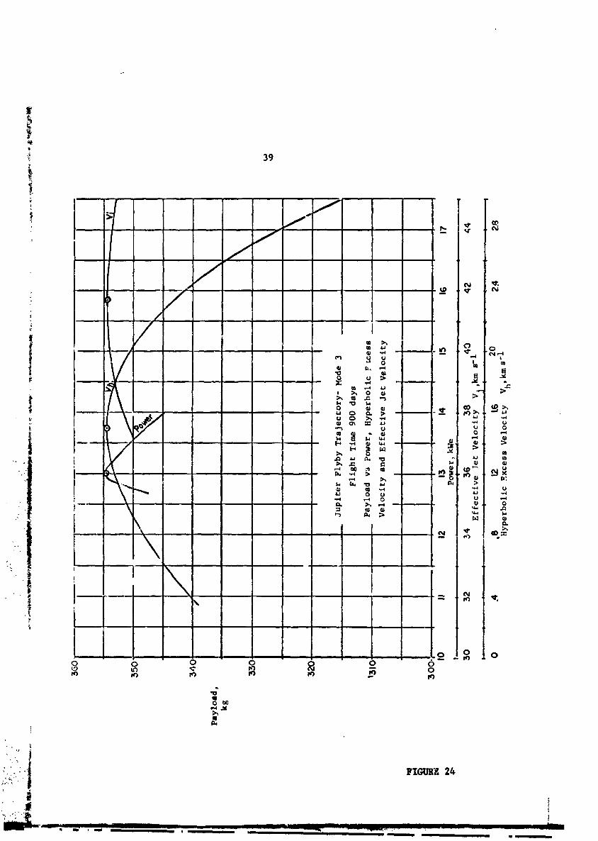
J u p i t e r Flyby T r a j e c t o r y - Mode 3 , F l i g h t Time 900 days , Payload vs Power, E f f e c t i v e Jet Ve loc i ty and Hyperbolic Excess Ve loc i ty
S o l a r E l e c t r i c P rope l l ed As te ro id Rendezvous a t R = 2.0 AU
Sola r E l e c t r i c Propel led As te ro id Rendezvous a t R = 3.0 AU
Sola r E l e c t r i c Propel led As te ro id Rendezvous a t R = 3.5 AU
Sola r E l e c t r i c Propel led As te ro id Rendezvous a t R = 4.0 AU

v i i
TABLES
Table No.
1
2
3
4
5
6
7
8
T i t l e - Solar E l e c t r i c Propelled Mars Orbi ter 1971
Solar E l e c t r i c Propelled Mars Orbi ter 1973
Solar E l e c t r i c Propelled Mars Orbi te r 1975
Solar E l e c t r i c Propelled Mars Orbi te r 1977
Solar E l e c t r i c Propelled Mars Orbi te r 1979
Launch Vehicle Comparison - Jupi te r Flyby
Solar E l e c t r i c Asteroid Rendezvous
Solar E l e c t r i c Asteroid Fly-Through Trajectory 5 P e 1
Solar E l e c t r i c A8 t e ro id Fly-Through Trajectory Type 2

I. INTRODUCTION
I n the f a l l of 1965 a r e p r e s e n t a t i v e of the O f f i c e of Advanced
Research and Technology, NASA Headquarters s o l i c i t e d the h e l p of the ASMAR
Program i n c a r r y i n g o u t some t r a j e c t o r y ana lyses f o r s o l a r e l e c t r i c pro-
p e l l e d s p a c e c r a f t which c e r t a i n developments i n s o l a r a r r a y technology
appeared t o make p r a c t i c a b l e . S t u d i e s had been undertaken by s e v e r a l indus-
t r i a l concerns under c o n t r a c t t o the J e t Propuls ion Laboratory, and the
ASMAR Program work was t o be coordinated w i t h t h i s e f f o r t . A new c o n t r a c t ,
NSR 31-001-078 was awarded t o suppor t the s o l a r e l e c t r i c miss ion a n a l y s i s
and the work was d i r e c t e d by M r . J. Mull in of OART and Mr. J. W. Haughey of
t h e Launch Vehic les and Propuls ion program^ Div i s ion , O f f i c e of Space Science
and Appl ica t ions , NASA Headquarters, who was a l s o monitor o f the ASMAR Basic
Program under Contract NASr-231.
ASMAR Program c o n t a c t a t the J e t Propuls ion Laboratory was M r . .T. W.
StearnR, A s s i s t a n t Manager, Propuls ion Research and Advanced Concept$ Sec t ion ;
and a d o c t o r a l cand ida te i n the ASMAR Program, Mr. G . A. Hazel r igg, J r . , was
ass igned t o JPL f o r the pe r iod February-September 1966 t o engage i n the work
t h e r e on computer ana lyses and programming and provide c l o s e l i a i s o n . Work
a t P r ince ton was c a r r i e d o u t , under the o v e r a l l l e a d e r s h i p of Mr. J. P. Layton,
by Drs. P. M. Lion, M. Haadelaman and C. N. Gordon wi th programming a s s i s t a n c e
provided by A n a l y t i c a l Mechanics Assoc ia tes , Incorporated r e p r e s e n t a t i v e s ,
e s p e c i a l l y M r . J . H. Campbell.
Having made a t imely c o n t r i b u t i o n and completed a c e r t a i n body of
work t h a t approximated the under taking i n i t i a l l y accepted p l u s some pre l iminary
a s t e r o i d b e l t miroion ana lyses , the e f f o r t by the ASMAR Program under c o n t r a c t
NSR 31-001-078 war terminated on 30 September 1967; however, a con t inu ing
i n t e r e s t i n and c a p a b i l i t y f o r t r a j e c t o r y and miss ion a n a l y s i s w i t n e o l a r e l e c t r i c
p ropu l r ion w i l l be maintained under the ASMAR Barjc Program.

11. MARS ORBITER CHbCK
A. T r a j e c t o r y Check of So la r E l e c t r i c Propel led Mars O r b i t e r s - 1971, 1973, 1975, 1977 and 1979
Hughes A i r c r a f t Company, under c o n t r a c t t o the J e t Propuls ion Labo-
r a t o r y , produced a n e x t e n s i v e s tudy of s o l a r - e l e c t r i c p rope l l ed Mars o r b i t e r
and J u p i t e r f lyby miss ions . (I)* Their t r a j e c t o r y r e s u l t s f o r the Mars o r b i t e r
conta ined c e r t a i n op t imiza t ions , allowed f o r s p a c e c r a f t l i m i t a t i o n s and f o r
p lane ta ry p e r t u r b a t i o n s . A t t h e r e q u e s t of NASA Headquarters, a modified ITEM
program (descr ibed below) was used by t h e ASMAR Group a t P r ince ton t o p r o ~ i d e
a check on the Hughes' r e s u l t s f o r the Mars o r b i t e r . The p re l iminary r e s u l t s -
** ** shown on Tables 1 through 5 and Figures 1 through 5 y i e l d a s u b s t a n t i a l
check of the Hughes da ta . However, Hughes was unable t o supply a l l the neces-
s a r y inpu t d a t a i n s u f f i c i e n t d e t a i l f o r a d e f i n i t i v e check. Thus, the
d i f f e r e n c e s shown i n the above r e s u l t s could no t be r e f i n e d and t h e a t t empt
t o o b t a i n a b e t t e r check was abandoncd.
B. The Modified ITPl Program
To check the Hughes' r e s u l t s the ASMAR Group undertook a gene-' r e w r i t e
of the ITEM Computer program which was obta ined from Goddard Space F l i g h t Center .
The ITEM program is a multi-body t r a j e c t o r y program us ing t h e Encke
method uf i n t e g r a t i o n . Changes incorporated i n t h i s program by the ASMAR Group
can be d iv ided i n t o (a) changes t o inc rease f l e x i b i l i t y i n the number and type
of problem which can be handled by t h i s program e n i (b ) c h a n ~ ? s t o improve the
e f f i c i e n c y of the computational procedures used.
* Supersc r ip t numbers i n pa ren theses i n d i c a t e References l i s t e d a t t h e end of t h e r e p o r t .
** Tables and F igures appear fo l lowing t h e f i r s t page of t e x t on which they a r e mentioned.

PRE
LIM
INA
RY
TA
BLE
1
So
lar
Ele
ctr
ic P
rop
elle
d M
ars
Orbiter
1971
Cal
end
ar D
ate
Juli
an
Dat
e
Lea
ve E
art
h s
ph
ere
of
infl
ue
nc
e,
To
(t
0
hrs
) M
ay
8,
1971
24
4108
0.4
38
2
-2
Vie
-Viv
a E
ner
gy
, C
g =
8.
2842
50 km
s
Arr
ive
nea
r.M
aro
, Tf
(t
= 2
30 d
ays
+ 3
hrs
) D
ec
25
, 1
97
1
2441
310.
563
Tra
nsf
er
Ang
l*.
=
172,
.888
O
Ea
rth
E
ph
emer
is
Hug
hes
S/C
M
ass,
kg
m
25
14
.3
Ra
tio
SIC
Mas
s @
Tf/
T0
- 1
App
roac
h S
pee
d
to M
ars,
km
s
1 N
ovem
ber
1966
Mar
s E
ph
emer
is
Hug
hes
Mod
. IT
EM
A
(MI-
H)

Soldr Electric Propelled Mars Orbiter 1971
Launch on May 8, 1971 Fl ight Time 231 days
FIGURE 1 --


Solar Electric Propelled Mars Orbiter 1973
Launch on July I&, 1973 Plight Time 290 days

PREL
IMIN
AR
Y
TABLE
3
So
lar E
lec
tric
P
rop
elle
d
Mar
s O
rbit
er
1975
Cal
end
ar D
ate
Julian D
ate
Vis
-Viv
a E
ner
gy,
Lea
ve E
arth
sp
her
e of
in
flu
ence
, to
(t
= 0 h
rs)
Au
g
17
, 19
75
2442
641.
7036
2
-2
C3 =
5.5
9758
9 km
e
Arr
ive near M
ars,
Tra
nsf
er A
ngl
e =
Tf (
t
= 4
00 d
ays
+ 1
0.5
hrs)
Sep
20,
19
76
2443
042.
141
~4
6.2
98
~
Ear
th
Ep
hem
eris
H
ughe
s
S/C
M
ass,
kg
m
2395
.2
Ra
tio
S/C
M
ass
@T
~/
T~
2 N
ovem
ber 1966
Mar
s E
ph
emer
is
Hughes
Mod
. IT
EM
A(M
I-H
)
App
roac
h S
pee
d
to M
ars,
km s-I

Solar Electric Propelled Mars Orbiter 1975 ,
Launch on Aug 17, 1975 Flight Time 400 days
. , FIGURE 3

. ..
PREL
IMIN
AR
Y
Sol
ar E
lect
ric
Pro
pel
led
Mar
s O
rbit
er
1977
Cal
end
ar D
ate
Ju
lia
n D
ate
Lea
ve E
arth
sp
her
e o
f in
flu
ence
, to
(
t =
0 h
rs)
Sep
6
, 19
77
2443
393.
2549
2
-2
Vie
-Viv
a E
ner
gy,
Cj
= 4.
0621
34 km
s
Arr
ive
nea
r M
ars,
Tf
(t =
430
day
s +
6 h
rs)
Nov
11,
19
78
2443
823.
505
Tra
nsf
er A
ngl
e =
27
3.59
7O
Ear
th
Eph
emer
is
Hug
hes
Ap
pro
ach
Sp
eed
to M
ars,
km s'l
1 N
ovem
ber
1966
- Mars,
- ~
ph
emk
r i&
Hug
hes
Mod. ITEM
- A
m-H
)

Solar Electr ic rope l l ed Mars Orbiter 1977
Launch on Sep 6 , 1977 Fl ight Time 431 days


Solar E l e c t r i c Propelled Mars Orbiter 1979
Launch on Oct 1, 1979 F l i g h t Time 406 days

13
(1) Changes t o increase f l e x i b i l i t y
(a) The program has been converted i n t o a subroutine capable of
i n t eg ra t i ng a t r a j ec to ry eegment, so t ha t a t r a j ec to ry of any configurat ion
can be created by making mult iple c a l l s on the i n t eg ra t i on rou t ine .
(b) The number of p lane ts has been increased from four t o
nine.
(c) The a b i l i t y t o s top the t r a j ec to ry prec ise ly on a given
time, f l i g h t path angle, or radius msgnitude has been included. This allows
more freedom i n the s e l ec t i on of parameters for i t e r a t i o n and optimization.
(d) In a d d i t i m t o programmed t h r u s t modes, t he a b i l i t y t o
inzegrate the ad jo in t equations has been included.
(2 ) Changes t o increase e f f ic iency
(a) Time has been replaced by be t a as the independent va r i ab l e
of t he in tegra t ion . Beta is defined by the following equation:
where a is the semi-major ax i s of t he o r b i t and 8 is t h e incremental
eccent r ic anomaly. This change allows Kepler ' s equation so lu t ion t o be
obtained without i t e r a t i o n , and it allows a more favorable s tep s i z e t o be
chosen for the numer i c a l i n t eg ra t im.
(b) The ephemeris rou t ine was modified t o place a l l necessary
ephemeris d a t a in core a t the same time. This e l iminates tape manipulation
during the computation of a t r a j e c t o r y but r e s t r i c t s t he program t o computers
of a t l e a s t 65K words of core s torage.
(c) The in t eg ra to r has been changed from. s i n g l e s t e p t o multi-
l i n e integrat ion. A t ab l e of 2.5 po in t s is used. The value o i t h i s is:
i The number of Runge-Kutta s t eps necessary for s t a r t i n g
14
is reduced. This a l lows s t a r t i n g of the s i x t h o rde r i n t e g r a t i o n i n about
one- t h i r d of the time p rev ious ly requ i red .
( i i ) Updating of the t a b l e is more e f f i c i e n t s i n c e i t i a on ly
requ i red once every 18 s t e p s i n s t e a d of every s t e p .
va lues a r e
These a r e :
c o r r e c t o r .
( i i i ) P len ty of p o i n t s a r e a v a i l a b l e f o r i n t e r p o l a t i o n i f
d e s i r e d which a r e not conta ined e x a c t l y i n t h e t a b l e .
( i v ) E d i t i n g of the t a b l e s is more e f f i c i e n t .
(d) Three nodes of i n t e g r a t i o n ( a l l s i x t h o r d e r ) h w e been inc laded .
( i ) Backwards d i f f e r e n c e p r e d i c t o r only .
( i i ) Backwards d i f f e r e n c e p r e d i c t o r w i t h a c e n t r a l d i f f e r e n c e
( i i i ) I t e r a t i v e c e n t r a l d i f f e r e n c e c o r r e c t o r .
Two modes of s t a r t i n g a r e included:
( i ) 4 t o 1 Runge-Kutta and backward d i f f e r e n c e p r e d i c t o r .
( i i ) I t e r a t i v e c e n t r a l d i f f e l ence c o r r e c t o r .
These modes a l low any necessary i n t e g r a t i o n accuracy w i t h a c o r r e s -
ponding amount of ~ m p u t e r time.

111. JUPITER FLYBY STUDY
A. I n t r o d u c t i o n
Advances i n hardware technology of s o l a r powered, e l e c t r i c rocke t
propel led space v e h i c l e s have, i n r e c e n t y e a r s , been s u f f i c i e n t t o j u s t i f y
examination of the p o s s i b l e use fu lness of t h i s Fype of p ropu l s ion i n two
ways: (1) performance of h igher energy miss ions wi thou t r e q u i r i n g upra ted
launch v e h i c l e s , and (2) e a r l y t e s t i n g of advanced e l e c t r i c r o c k e t t h r u s t e r
technology w2thout the r a d i a t i o n problems inheren t i n nuc lea r powered systems.
The f i r s t way r e q u i r e s t h a t s o l a r e l e c t r i c p rope l l ed v e h i c l e s compare favorably
t o e x i s t i n g systems f o r s u f f i c i e n t l y important c l a s s e s of miss ions . Indeed,
i f t h i s were s t r o n g l y the case , then s o l a r power could become a key s t e p on
the road t o f u t u r e advanced p ropu l s ion s y s terns. Recognizing the p o s s i b i l i t i e s
f o r solar-powered v e h i c l e s , t h e J e t Propuls ion Laboratory (JPL) i n 1966 incor-
porated s t u d i e s of solar-powered v e h i c l e s i n t h e i r advancel programs. An
examination was conducted of the p o s s i b l e m i s s i ons i c t o which solar-power might
f i t , and from the r e s u l t i n g p o s s i b i l i t i e s , the J u p i t e r f lyby was chosen f o r an
in-depth study. This miss ion was chosen because i t r e p r e s e n t s the f i r s t advanced
mission which might b e n e f i t t o a major e x t e n t from s o l a r - e l e c t r i c propuls ion.
This resea rch was undertaken t o suppor t the .TPL e f f o r t by a n a l y t i c a l and pro-
g r a m i n g work inc lud ing c l a r i f i c a t i o n of the optimum mode by c a r r y i n g o u t the
pre l iminary miss ion ana lyses r epor ted he re in .
B. Optimum Sola r E l e c t r i c Propel led J u p i t e r Flyby T r a j e c t o r i e s
A s tudy of optimum f lyby t r a j e c t o r i e s t o J u p i t e r r ~ s i n g s o l a r e l e c t r i c
propuls ion f o r f l i g h t t imes from 600 t o 900 days i s repor ted i n t h i s s e c t i o n .
The launch v e h i c l e used was t h e A t l a s S ~ ~ 3 C / ~ e n t a u r . A "flyby" t r a j e c t o r y
matches t h e p o s i t i o n of the t a r g e t p l a n e t - i n t h i s c a s e J u p i t e r - w i t h no

16
cons t r a in t on the ve loc i ty . Optimum i n t h i s repor t means maximized payload
o r ne t spacecraf t mass a t the t a rge t .
Low-thrust opt imizat ion of the J u p i t e r f lybys was accomplished by
the Gordon 2 computer program which was developed a t Pr inceton under Contract
NASr-231. This program is a two-body, two-dimensional, f i n i t e t h r u s t , t r a -
jectory opt imizat ion program. I n add i t i on t o optimizing the t h r ~ . s t d i r e c t i o n
and the switch times of the propulsion system, o ther s i g n i f i c a n t parameters
associated with the t r a j e c t o r y can be optimized such a s j e t ve loc i ty , power
l eve l , hyperbolic excess ve loc i ty , launch-time and f l i g h t time.
Modifications t o the program f o r t h i s study include
(1) The capab i l i t y of parer v a r i a t i o n a s a funct ion of s o l a r
rad ius , including the appropriate a d j o i n t equations.
(2) Subroutines which give the launch veh ic l e performance f o r a
v a r i e t y of launch vehic les , and so l a r a r r a y and e l e c t r i c rocket ion engine
performance.
(3) Addition of an ephemeris rou t ine which computes i n i t i a l and
f i n a l condi t ions used i n the i t e r a t i o n , given the J u l i a n launch da t e and t r i p
t i m e . A second rout ine searches the ephenxiris tape f o r launch configurat ions
which correspond t o given boundary condi t ions. This permits the i d e n t i f i c a t i o n
of appropriate launch da t e s which correspond t o optimum angle t r a j e c t o r i e s .
(4) Addition of sweep c a p a b i l i t i e s fo r s eve ra l parameters including
launch da t e , t r i p time, j e t ve loc i ty , power, and hyperbolic excess ve loc i ty .
(5) Provision fo r a f i n i t e hyperbolic ve loc i ty a t the a r r i v a l planet .
The magnitude of the hyperbolic ve loc i ty can be spec i f i ed and i t s d i r e c t i o n
spec i f ied o r optimized.

17
(6) Improved i n t e g r a t i o n and i t e r a t i o n p r o c e d w e s . The i n t e g r a t i o n
was improved from second o r d e r t o f o u r t h o rde r i n the p red ic to r - :o r rec to r
scheme. The i t e r a t i o n r o u t i n e s were improved f o r g r e a t e r s t a b i l i t y through
the i n c l u s i o n of a n automat ic c o r r e c t i o n l i m i t e r . The r e s u l t s a r e a f a s t e r
and more uniform convergence.
The fol lowing assumptions were used i n t h e J u p i t e r f lyby t r a j e c t o r y
op t imiza t ion :
(1) The space v e h i c l e is considered t o be comprised of power supply
and t h r u s t e r s , p r o p e l l a n t , p r o p e l l a n t tankage and payload. The payload inc ludes
a l l items no t included i n the o t h e r c a t e g o r i e s . Mass of t h e power system is
assumed t o be p r o p o r t i o n a l t o t o t a l power. The power system s p e c i f i c mass, a , - 1
is taken t o be 30 kg kWe throughout t h e s tudy (except f o r the s e n s i t i v i t y
ana lyses ) . Tankage mass is assumed t o be p r o p o r t i o n a l t o f u e l expended, wi th
t h e f a c t o r of p r o p o r t i o n a l i t y 0.05. No s p e c i f i c al lowance is made f o r s t r u c t u r e
mass, :o i t must be considered p a r t of the payload.
(2) J u p i t e r and E a r t h were assumed t o be i n cop lanar , c i r c u l a r o r b i t s .
Departure and a r r i v a l coord ina tes were taken t o be t h e p l a n e t a r y c e n t e r s and
t h e i r mass was ignored dur ing the low t h r u s t h e l i o c e n t r i c t r a j e c t o r y . Depar-
t u r e and a r r i v a l d a t e s were taken t o g ive a n optimum c e n t r a l ang le .
(3 ) The launch v e h i c l e was t h e A t l a s SLV3CICentaur. The r e l a t i o n s h i p
between i n j e c t e d mass and hyperbol ic excess v e l o c i t y was ob ta ined i r o n the NASA
OSSA Launch Vehicle Es t ima t ing Fac to r s (2) and is shown i n Figure 6 a s a curve
f i t and i ts d e r i v a t i v e s .
( 4 ) Except f o r s e n s i t i v i t y ana lyses a l l t r a j e c t o r i e s optimized power
l e v e l , j e t v e l o c i t y , and hyperbol ic excess v e l o c i t y .

LAUNCH VEHl CLE PERFORMANCE
Launch Capability of the Atlos (SCV3C)/Centour_ far the period 1973-1977
Ref I N A S A , Launch Vah~ch Ettimakg f i c t m for Cirnrrutiaq OSSA Ptotpectut 1967, Novunkr 1966
Cuw Fit of Glow Spococmft Mom Vwmus Hypubolle Ercerr Velocity

(5) Propuls ion system e f f i c i e n c y is assumed t o be a f u n c t i o n of
j e t v e l o c i t y . This r e l a t i o n s h i p , was provided by NASA Headquarters(3) and is
shown i n Figure 7.
(6) The v a r i a t i o n of s o l a r power w i t h d i s t a n c e from the sun was
(1) obta ined from the Hughes Study Report . The r e l a t i o n s h i p is shown i n
Figure 8.
(7 ) The range of f l i g h t t imes i n v e s t i g a t e d was 500 t o 900 days.
One of the i n t e r e s t i n g r e s u l t s of the s tudy was the i d e n t i f i c a t i o n
of t h r e e d i f f e r e n t modes f o r s o l a r e l e c t r i c p rope l l ed J u p i t e r f lybys over the
range of f l i g h t times i n v e s t i g a t e d . Mode 1, shown i n Figure 9, is a d i r e c t
f l i g h t w i t h t h r u s t always a c t i n g i n the g e n e r a l d i r e c t i o n of the v e l o c i t y and
energy always inc reas ing . Travel ang les f o r t h i s mode a r e t y p i c a l l y f o u r
r ad ians . Mode 2 , shown i n Figure 10, r e q u i r e s a n i n i t i a l r e t r o - t h r u s t thus
dec reas ing energy and a l lowing the s p a c e c r a f t t o f a l l i n toward t h e Sun. A t
the p e r i h e l i o n of t h i s t r a j e c t o r y , where power i s maximum, the t h r u s t d i r e c t i o n
has swung around and now suppor t s the motion s o the s p a c e c r a f t energy i n c r e a s e s .
Travel ang les f o r t h i s mode a r e t y p i c a l l y s i x r a d i a n s . Mode 3, shown i n
Figure 11, has t h r e e d i f f e r e n t phases where the t h r u s t a l t e r n a t e l y s u p p o r t s ,
opposes ana a g a i n suppor t s the motion and the energy is correspondingly inc reased ,
decreased, and inc reased . These t r a j e c t o r i e s a r e t y p i c a l l y e i g h t r a d i a n s .
The p r i n c i p a l r e s u l t , a p l o t of payload vs t r a v e l time is shown i n "
Figure 12. For s h o r t t r a v e l t imes, Mode 1 is the b e s t ; whereas, f o r longer
t r i p t imes Mode 3 is b e s t . For the p a r t i c u l a r v e h i c l e c h a r a c t e r i s t i c s used,
the c rossover p o i n t is about 870 days. Mode 2 is never optimum (except l o c a l l y ) .
F igures 13, 14 and 15 show f u r t h e r d e t a i l s on Modes 1, 2 and 3 , r e s p e c t i v e l y :
power, hyperbol ic excess v e l o c i t y and j e t v e l o c i t y a r e p l o t t e d ve r sus t r i p time.

ELECTROSTATIC (ION) ELECTRIC ROCKET PERFORMANCE
Electron Bombardment Thruster with Cesium fw the Period 1973-1977
Ref: N A S A(JBMullin) Letter Doted January 19, 1967
0 10 20 30 40 60 60 70 2
0- -- -2 . .
- 4
-6 -
-8 ,
-I0 - - 1 0 10 20 30 40 50 60 70
. Effective Jot Valodtv Voj , km s - 1
Curve Flt, Including Firat and Second Dorivotlve~,ot Ovw0Il Eftioncy VD. Effodiw 3.1 Velocity
1 .EJ~F,L. .--

Curve Fit of Poww Vurua Rodlur

Jupiter Flyby Trajectory - Mode 1 ,
Flight Time 600 days Travel Angle 3.25 rad.
Arrows indicate thrust direct ion
FIGURE 9

Arrows indicate thrust direct ion
Jupiter Flyby Trajectory - Mode 2
Flight Time 600 days Travel Angle 5.65 rad.


10
Pow
er , kW
e
2.6
2.9
3.2
3.5
38
4.!
4.4
4
.7
50
H
yp
erb
oli
c E
xc
ess
Ve
loc
ity
Vl,,
krn
S
55-
-
2s
52
- 1
Is
E
ffe
cti
ve
T
et
Ve
loc
ity
b
km
s 35
S
I
J

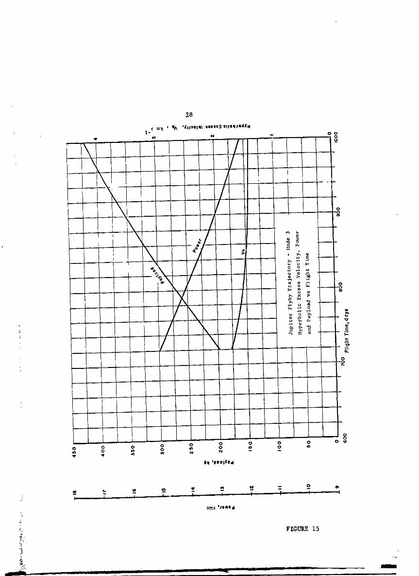
FIGURE 15

Figure 16 shows a t yp i ca l (600 day) Mode 1 t r a j e c t o r y p r o f i l e (See Figure 9 ) ;
s imi l a r ly , Figure 17 shows a p r o f i l e f o r 900 day Mode 3 t r a j e c t o r y (See Figure
11).
The t r a jec tor iea j u s t described optimized power l eve l , j e t ve loc i ty ,
and hyperbolic excess ve loc i ty a s wel l a s the t h r u s t program. The s e n s i t i v i t y
of Mode 1 t r a j e c t o r i e s t o off-optimum condi t ions and v a r i a t i o n of prescr ibed
parame ters was a l s o s tudied a s described below.
Figure 18 shows the va r i a t i on of payload versus hyperbolic excess
ve loc i ty f o r a number of f l i g h t times. I n t h i s c-we the optimum is q u i t e f l a t .
Figure 19 shows the e f f e c t on payload of an improvement i n powerplant s p e c i f i c
mass over a range of f l i g h t times. The o r i g i n a l t r a j e c t o r i e s vere computed
- 1 using a t 30.0 kg We . The e f f e c t of a reduct ion t o a = 27.0 and 24.0 is
shown. For t h i s p l o t , t r a j e c t o r i e s were r e -~p t imized using these new values
of a . Over the range inves t iga ted the e f f e c t on ne t mass is f o r p r a c t i c a l
purposes, l i n e a r wi th a , and independent of f l i g h t time. Figure 20 shows the
e f f e c t of an improvement i n t h rus t e r system e f f i c i ency over a range of f l i g h t
times. For t h i s p l o t , the t vs V. curve, o r i g i n a l l y provided by Reference 3 J
was increased by 10 and 20%. The t r a j e c t o r i e s were then re-optimized. Again
the improvement appears t o be r e l a t i v e l y independent of f l i g h t time.
To determine the e f f e c t upon payload of va r i a t i ons i n power l eve l ,
j e t ve loc i ty , and hyperbolic excess ve loc i ty , two example t r a j e c t o r i e s were
chosen. The f i r s t is a Mode 1, 600 day f l i g h t wi th payload of about 181 kg.
This d i r e c t t r a j e c t o r y i 8 s imi l a r t o t h a t p lo t t ed i n Figure 9, and the a c t u a l
t r a j ec to ry p r o f i l e is shown i n Figure 21. S e n s i t i v i t y of payload t o t he a b w e
parameters is shown i n Figure 22.

I I
I I
I
I
I J
up
iter
F
lyb
y T
raje
cto
ry -
Mod
e 1
600
day
e
Pow
er
Fa
cto
r,
Th
rust
Fa
cto
r,
Th
rust
An
gle,
Rad
ius
and
Tra
vel
A
ngl
e v
s F
lig
ht
Tim
e
Th
rust
Fa
cto
r &
P
ower
F
act
or
Fli
gh
t T
ime,
d
ay
e

FIGURE 17

Ju
pit
er
Fly
by
Tra
ject
ory
- M
ode
1 P
ay
loa
d v
s H
yp
erb
oli
c E
xce
ss V
elo
cit
y
for
V
ari
ou
s F
lig
ht
Tim
es

Pay
load
,
800
900
Flight Time,
day
8

#K
)
Pa
ylo
ad
,
, P
ay
loa
d v
s F
lig
ht
Tim
e fo
r V
ari
ou
s T
hru
ster
Sys
tem
Eff
icie
nc
ies
800
900
Fli
gh
t T
ime,
d
ay
s


Flig
ht n
me,
days
- : -

3 7
The other t ra jec tory chosen for study vas a Mode 3, 900 day f l i g h t
with payload of about 355 kg. Tho plo t of a s imilar t ra jec tory is shown i n
Figure 11 and the actual t ra jec tory p r o f i l e i n Figure 23. Sens i t iv i ty of the
payload t o pcwer, e f fec t ive jet veloci ty and hyperbolic excess ve loci ty is
sham i n Figure 24.
Referring t o the sharp f a l l o f f of payload with power va r i a t ion seen
i n Figures 22 and 24, it should be noted t h a t both ef fec t ive jet veloci ty and
hyperbolic excess veloci ty (and thus i n i t i a l mass) were held constant while
the power was varied. Therefore, varying power is essen t i a l ly the same as
varying init.i.1 th rus t t o mass r a t io . Previous studies a t Princeton have
sham a l so t h a t the payload was qui te sensi::ir.. t o t h i s parameter. I f
e f fec t ive jet veloci ty and hyperbolic excess ve loci ty had been re-optimized
f o r each new power level a s has been done i n a number of previously studies,
the f a l l o f f of payload with power would be more gradual and the curve would
l i e abwe tha t shown in Figures 22 and 24.
An in teres t ing comparison of the capab i l i t i e s of three launch
vehicles was made using the Gordon Program: Atlas (SLV3C) /Centaur,
Titan 111-C (1207) /Centaur and Saturn IBICentaur . The resu l t s are shown i n
Table 6 below. The mission is a 600 day, so lar e l e c t r i c , Jupi ter flyby,
assiuning coplanar c i r cu la r o rb i t s . The t r a j ec to r i e s are f u l l y optimized:
thrus t ing program, e f fec t ive j e t veloci ty, i n i t i a l acceleration, power and
hyperbolir excess velocity. Transfer angle has a l s o been optimized. The
resu l t ing payloads are:
Atlas (SLV3C) /Centaur 174.86 kg
Titan 1114 (1207) /Centaur 1943.39 kg
Saturn I~ ICen taur 1778.50 kg
The speci f ic mass of the powerplant was taken t o be 26.0 kg meo1. Tankaw
and s t ruc ture fac tor were assmed t o be .06 and .08, respectively.


I n i t i a l Mass, kg
Powerplant , kg
Table 6
Launch Vehicle Conwariron - Jupiter Flyby
Mode 1 - Flight Time 600 daya
Propellant, kg
Propellant Tanks, kg
Structure, kg
Payload, kg
I n i t i a l Power, We
Efficiency, q
Hyperbolic Excess Velocity, km s'l
Effect ive Je t Velocity, km 8-1 32.532
I n i t i a l Acceleration, m s-i 0.5583*10-~ 0 . 3 2 7 2 ~ 1 0 - ~

IV. ASIEROID BELT EXPLORATION MISSIONS
A. Introduction
The i n t e r e s t i n and value of s c i e n t i f i c missions t o explore the
as tero id b e l t has been discussed i n a number of published papers and reports . (4- 10)
I n addit ion t o s c i e n t i f i c i n t e r e s t i n the as tero ids per se, there is a l s o the
need t o know more about the as tero ids from the viewpoint of collision - avoid-
ance between the as tero ids and any interplanetary spacecraft passing through B
the b e l t as w e l l a s the contribution of the as tero ids t o the dangerous-sized
pa r t i c l e s and debris throughout the rest of the so la r system. (11-15) An
as tero id be1.t fly-through mission is examined i n Refs. 4 and 5. Four rendezvous
missions t o the as tero ids Eros, Ceres, Icarus, and Vesta, respectively, a r e
eramined-in Ref. 5. Since a l l of these mission s tudies a r e based upon chemical
propulsion, it was decided t o make some preliminary analyses based on so la r
e l e c t r i c rocket propulsion.
B. Discussion of Solar-Electric Asteroid Belt Trajectory Results
The f e a s i b i l i t y of optimal rendezvous t r a j ec to r i e s t o t a rge t s within
the as tero id b e l t , using a so la r -e lec t r i c propelled spacecraft, launched by one
of three des ignated boosters [Atlas (SLV3C) /Centaur, Ti tan 111-C (1207) /f:entaur,
or Saturn l ~ / ~ e n t a u r ] was i n i t i a l l y reported i n ASMAR Status Report dated
1 October 1967. 'I6) A omre complete set of da ta i r presented and s-;ired
i n t h i s report.
'The general pa t tern of the as tero id rendezvous t r a j e c t o r i e s is shown
i n the FRONTISPIECE.
Figures 25, 26, 27 and 28 show curves of payload m i n i t i a l so la r PI'
e l e c t r i c power a t 1 AU Po, hyperbolic excere veloci ty squared C and e f fec t ive 3 *

So
lar
Arr
av
Pow
er
4,0
00
Pay
load
PI
, kg
So
lar
Ele
ctri
c P
rop
elle
d A
eter
oid
Ren
dez
vou
s a
t R
- 2.0
AU
300
350
400
450
500
550
Fli
gh
t T
ime,
d
ays
Eff
ecti
ve
Jet
V
elo
city
Vo,
- - - - -20 16
Hyp
erb
olic
E
xces
s V
elo
city
S
qu
ared
,
-12
C3,
2 (k
m
8
4 0

FIGURE 26


Ryp
erb
ol i
c
Ex
cess
V
elo
city
30
Sq
uu
ed,
C?,
So
lar
Arr
ay
Pcw
er
7 5
1,6
00
Pay
load
,
So
lar
Ele
ctr
ic P
rop
elle
d A
ster
oid
Ren
dez
vou
s a
t R
* 4
.0 A
U
1 L
a~
nc
h~
eh
icle
s
Sat
urn
l~
/Ce
nta
ur
Fli
gh
t T
ime,
d
ays
Eff
ec
tiv
e
Je
t P
V
I V
elo
cit
y, V j *

j e t ve loc i ty V vs f l i g h t t i m e f o r the A t l a s ( S ~ ~ 3 ~ ) / ~ e n t a u r and the Saturn J 1~:centaur boosters , f o r rendezvous m;ssions t o r a d i i R = 2.0, 3.0, 3.5 and
4.0 AU, which includes the approxiamte rb.li.1 ex t en t of the a s t e ro id b e l t .
This da ta is a l s o presented i n tabular form i n Table 7. These t r a j e c t o r i e s
a r e fixed- time, two-dimensional optimized fo r M X ~ ~ W I payload wi th respec t
t o the t h r u s t program, P V C and t r a v e l angle. The following q u a n t i t i e s 0' y 3
a r e input data: e l e c t r i c rocket propulsion system s p e c i f i c mss fac to r a =
20.0 kg kweD1, (44 lb~ /kVe) , s t r u c t u r e f ac to r = 0.08, tankage f ac to r = 0.06,
t h rus t e r system e f f i c i ency rl = a funct ion of V (Figure 7), the s o l a r power 1
f a l l -o f f funct ion = a funct ion of s o l a r d i s tance R (Figure 8), and the launch
vehic le c h a r a c t e r i s t i c s . (2) The s p e c i f i c m a s s f ac to r is considered t o be repre-
s en t a t i ve of advanced s o l a r a r r a y technology i n the period when these missions
would be performed. These a r e rendezvous t r a j e c t o r i e s , which match the l oca l
he l i ocen t r i c c i r c u l a r o r b i t a l ve loc i ty a t each designated rad ius , R. Thus the
t r a j ec to ry matches the o r b i t of the average a s t e ro id , assumed c i r c u l a r . Match
t o prescribed e l l i p t i c a l o r b i t s i s e a s i l y obtainable , i f desired. Since the
a s t e ro ids are c lo se ly grouped about the e c l i p t i c plane, there i s not expected
t o be a s i g n i f i c a n t change i n payload performance between these two-dimensional
( e c l i p t i c plane) t r a i e c t o r i e s and a c t u a l three-dimer.siona1 ones. The jus t i f i-
ca t ion fo r t h i s statement is t h a t it i e knom t h a t f o r small o r b i t a l i n c l i n a t i o n
angles , which is the case here, there i s only a small payload performance penal ty i
(15) i fo r non-coplanarity, using e l e c t r i c propulsion on in t e rp l ane t a ry t r a j e c t o r i e s .
Figures 25 through 28 and Table 7 rhow c l e a r l y , assuming a minimum
payload l i m i t of about 340 kg (750 lb r ) , t h a t rendezvour mirr ionr wi th in the
e n t i r e a s t e ro td b e l t a r e f ea s ib l e using the Saturn lB/centrur booster and s o l a r
e l e c t r i c propulsion. The payload m s r e r , while funct ion of the t r i p time a s

47
Table 7
Solar Electric Aateroid Rendervou~
Net Electric Fin41 Je t Electric i I Final Tim (Final la88 Power Electric Exh4urt Engine C3 Ravel payload ? Radiur Pawarplent) a t 1 AU Pwer ~ e l o c i t y Efficiency Angle ~ a r r
m88 Po Pf
Saturn l ~ / ~ e n t a u r Plua Solar Electric
2.0 300 1245 123.6 37.7 30.0 60 17.8 2.66 695
' I I I
Optimal Thrurt, V s C 3 , Po. structure Factor -0.08 j
= 20.0 kg kwe-1 , . . . T.nk8g. Factor - 0. C3

ohown, remain amply adequate i n most cares f o r a wide spectrum of experileents,
comunicat ion capab i l i t i e s , tercmirul maneuverr, c r u i r i n g a m n g a numbetr of
loca t ions wi th in the a r t e r o i d b e l t , o r b i t i n g around o r surface-landing upon a n
as te ro id , e t c . A de tu i led examination of such experiarentr and terminal maneuvers,
while of considerable i n t e r e s t and importance, was beyond the planned rcope of
t h i s work, and has not been performed. The Atlar (SL~X)/Centaur boorter p lus
s o l a r e l e c t r i c propulr ion appears adequate (based upon the 340 kg minLrmrm pay-
load l i m i t ) a t R = 2.0 AU f o r t r i p timer g rea t e r than about 400 days, not
adequate a t R = 3.0 AU f o r t r i p times less than 700 days, marginally adeq -e
a t R = 3.5 Air f o r t r i p times grea ter than about 950 day8 and not adequate a t
R = 4.0 AU f o r t r i p times less than 1,000 days. Thus, i t appearr t h a t the
Atlas ( S ~ v X ) / ~ e n ~ u r booster plus s o l a r e l e c t r i c propulsion is marginally
s u i t a b l e f o r rendexvous missions t o region8 wi th in the a s t e ro id b e l t up t o
about R = 3.5 AU, depending upon the mximum allowable f l i g h t tima and the mini-
mum allowable p y l o a d mass.
It must be kept i n mind t h a t the s o l a r - e l e c t r i c powerplant masses a r e
not i nc1uded .h the above payloadr. This i r a n important point when making
comparisons with non-electr ic propelled rystemr, which requi re separa te rourcer
o f e l e c t r i c power, and which a r e usua l ly charged aga ins t the payload mass. On
the o ther hand, the optimum power l e v e l s a r e i n soma iur tancer lar~,er than prac- .- p;6,
t i c ab le with c e r t a i n cons t r a in t s such an sbroudr, e t c . v; i . .
under
u r w l
where
m r
The e l e c t r i c power ava i l ab l e a t the t r a j ec to ry terminal8 is l i s t e d
the heading Pi i n n b l e 7. The power a t any d i r t ance R i r given by the
equa t ion
Pi -.Po f(R) (1)
Po i r the i n i t i a l power a t 1 A U and f(R) is tha prercr ibed va r i a t i on of
with molar d i r tance R. For the Saturn l ~ / c e n t . u r , the terminal power

uaing a spacecraft antenna diameter of 7.5 f e e t , should be adequate for most
q : colnwnication mads, :md can provide a b i t r a t e of 20,000 bi t s / sec a t 5.0 AU
range t o Earth, uoing the 85 foot DSIF ground antenna. mi8 power level
(10 Kw) is a l s o adequate fo r the larger of two experimental radars mentioned
i n the following sec t ion of t h i s report . The d e s i r a b i l i t y of a te levis ion
capabil i ty, not nacessarily real-time, implies that high data r a t e s w i l l be
required a t ranges up t o 5.0 AU. For real-timc television, using Apollo te le-
v i r ion paraamters, FM modulation, 5.0 AU range, 85 foot ground antenna, 7.5 foot
spacecraft antenna, 160 kUe cf power would be required. This would be reduced
t o 30 kWe by use of an 18 foot spacecraft antenna.
The ci rcular ized rendezvous t r a j e c t a i a r &*weed abwe comprise
only o w subclass of the t o t a l number of potent ia l ly uoefrrl t r a j ec to r i e s t o
explore the asteroids. For example, another subclaas of mndezvous t r a j ec to r i e s
a r e rendemmus missions t o speci f ic named ast;lroida, with known o r b i t a l elements.
S t i l l other type8 of t r a j ec to r i e s , such as a (kruiser" or sp i ra l ing t ra jec tory
may provide be t t e r sampling of the t o t a l as tero id d i s t r ibu t ion within the b e l t ,
i f t h i s is the s c i e n t i f i c missron obj?ctive, i n radius (solar distance), i n
angle (circr~nsolar) and i n depth (direct ion conon1 t o e c l i p t i c plrne) than
rendezwwr t r a j ec to r i e s . Such missionr may accomplish more per mission do l l a r
mearured i n terms of data-gathering and i n accumlat ion of sc ien t i f ir: knowledge
d 3 t h n rede tvour t r a j ec to r i e s . Of c m r r e , it may be possible t o design rendez-
a
vow t r a j ec to r i e s which provide a good s u p l i n g of the b e l t p r io r t o o r even
rubrequent t o reaQtvour with s spec i f i c u t e r o i d , i f su f f i c i en t propulsion
cclpability ir available.
Another t ra jec tory o u b c l u r i r tba flyby o r fly-through type of
' ! 8i88gOa which can &liver more payload than the rendezvous type, but .fro har d

disadvantages, a s w i l l be discussed now. Two examples of fly-by or f ly -
through t r a j ec to r i e s were inwet iga ted br ief ly . The r e s u l t s a r e tabulated
i n Tables 8 and 9. The f i r s t t ra jec tory type (labeled Type 1, Table 8)
consis ts ,of a 450-day t r i p t o R = 4.0 AU. Optimal thrus t is used t o 8 - 2.0 AU,
then thrus t is cu t o f f , and the vehicle coasts t o 4.0 AU. The t ra jec tory goec
on be., nd 4.0 AU but was not computed. This t ra jec tory has the foi,awing
advantage over the rendezvous types: A so la r distance of 4.0 AU (spanning the
bel t ) is reached i n only 450 days, which tri? time is not achievable a t a l l ,
with any of the designated boosters, for the c i rcular -orbi t rendezvous type
trajectory t o R = 4.0 AU, and t h i s with payloads comparable t o those of the
c i r w l a r - o r b i t rendezvous ty; a t R = 2.0 AU. However, there a r e corresponding
disadvantages, such a s r m a l l e r t ravel angle (poorer circumeolar sampling)
and fa8 t e r t rans it time through the b e l t (increased exper inent observationa!.
d i f f i c u l t i e s ) compared with the open-angle c i rcular -orbi t rendezvous t ra jec-
tories . For example, fo r the Saturn lB/Centaur, compkrison between the above
450 day Type 1 t r a jectorv, and the 900-day c i rcul nr-orbit rendezvous t r a jec-
tory shows tha t the t ravel angle and time within the b e l t 4-2 t o 4 AU ) fo r the J
; l a t t e r a r e r'espectively each approximately twice tha t of the fo rmr . This is
t
shown i n Table 8.
It can be seen frorn Table 8 tha t the performattce of the Titan 111-C
(1207)/centaur and the Sa-.urn l~ /Cen taur boosters are very similar t o each
other. Part ly for t h i s reason an extensive separate s e t of t ra jec tory compu-
tat ions using the Titan booster was not undertaken. Another coaanent on
Table 8 (and 9) is tha t a powerplant syecif i c mass fac tor of a = 26.0 kg kwe-'
va8 wed instead of 20.0 kg kweol w e d for Table 7 , due t o the c-utat iw k i n g
done a t two d i f fe ren t time periods. While t h i r difference i n a can produce

51
Table 8
Solar Electric Asteroid Fly-Through Trajectory Type l*
Saturn 1 B Titan 111 C
I n i t i a l Pouer, Po, kUe 31.2 27.7
Effective Jet Velocity, V h 8-I J '
31.4 31.4
I imibo l i c Excess Velocity Squared,
-2 I n i t i a l Thrust Accel., R40, m s 0.30 x 10'~ 0.26 x 10'~
I n i t i a l Mss, mo, kg 3,475 3,530
Engine Efficiency, T
Payloadmss, m kg PI'
Saturn 1B =tan 111 c (1207) /Centaur /Centaur
Travel Trave 1 D i s tance , AlXSle, Distance, W l e ,
AU tad. AU rad.
within bel t 2-6 AU): within bel t (u 2-4 AU) : time = 300 days t h e = 300 days angle = 0.76 rad. angle = 0.8 rad.
For comparison: Saturn lB/Centaur, 900-day, 4.0 AU rendezvous: within belt: tip = 700 days, angle = 1.7 rad.
* Type 1 trajectory: 450 days t o R = 4.0 AU. timal thrust control t o n = 2.010, coast to.4.OAU. a - 26.0 4 -3, tankage factor = 0.06, structure factor = 0.08.

Table 9
Solar E lec t r i c Asteroid Fly-Through Trajectory Type 2*
Titan I II-C(l207) /centaur
I n i t i a l pawer, Po, kYe 53.3
Jet exhaust veloci ty, V b s-' 31.4 j '
Byperbolic Exres Velocity Squared, C,, (h s-1) 5 53.7
-2 I n i t i a l th rus t accel., PIIO, r s 0.30 t
Engine efficiency, q 0.53 . .
Travel Ti=, Distance , h g l e , Mass, days AU rad . Normalized
Wiihin b e l t (N2-4 AU), outward-bound leg: Time = 310 days Angle = 0.69 rad.
* Type 2 t rajectory: 700 days t o R = 4.5 AU. Optimal continuous thrust .
Terminal veloci ty = 0, tangential veloci ty open and l e s s than local c i r cu la r veloci ty, so tha t spacecraft f a l l s back in to be l t .

meaningful difference
53
.oad, i t is not large enough t .o invalidat :e the
overa l l remarks on comparative performance betwen rendezvous and nonrendezvous
subclasses of t r a j ec to r i e s made i n the preceeding paragraph.
rite second type of t ra jec tory (labeled Type 2, Table 9) cons is ts
of a 700 day t r i p t o R = 4.5 AU, optimal continuous thrus t , terminal r a d i a l
veloci ty = 0 and terminal horizontal veloci ty = open, but less than local
c i r c u l a r ve loci ty a t R = 4.5 AU, s o tha t the spacecraft f a l l s back i n t o the
bel t . 'Ihe r s s u l t s (Table 9) are not very pranising, as compared t o p r e . i ~ u ~
t r a j ec to r i e s , i n terms of payload, and time and angle spent within the belt
on the outb.mnd leg. A possible s ign i f i can t improvement might be achieved
by shortening the t r i p tLae soarewhat by z e ~ e c i u g the radius t o R = 4.0 AU,
and by including the re turn (inbound) l eg contributions t o the time and angle
within the bel t .
A very novel poss ib i l i ty A s a so la r -e lec t r i c mission t o accomplish
0 a complete 360 sampling i n circumsolar angle i n the b e l t i n a reasonable
time by use of a retrograde so la r orbi t . It is proposed t o e s t ab l i sh such an
o r b i t by means of a Jupiter swing-by, t o put the spacecraft in to a retrograde
c i r cu la r o r e l l i p t i c o r b i t within the bel t . Oae disadvantage of such a t r a -
jectory would be the very high r e l a t i v e ve loc i t i e s between the as tero ids i n
t h e i r posigrade o r b i t s and the spacecraft i n its retrograde o rb i t . More study
is needed t o e s t ab l i sh t ra jec tory f e a s i b i l i t y , and t o aesess the aggravated
experinental d i f f i c u l t i e s due t o the high spacecraft veloci ty r e l a t i v e t o the
asteroids.

C. Spacecraft Radar
The desirabi l i ty of an on-board radar for detection, range, angle
and other possible measurements on asteroids i n a program aimed a t exploration
of the be l t is discussed i n the l i tera ture . ( 4 s 5 ) In addition, s o r type of
radar is required t o furnish input data for asteroid col l is ion avoidance
sys terns. 11s12s13 For exploration, the radar vould need to be supplemented
by other equipeent for detailed iieasuremnts of asteroid size, o rb i ta l elements,
rotation, and surf ace cbarac teris t ics . For col l is ion avoidance, additional
subsystems would be needed for asteroid target tracking, trajectory prediction,
and nmneuverability coe~and and control.
A study of the feasib5li ty of such a radar was completed, and is
reported i n de t a i l i n Ref. 18, and i n slmmary form in Ref. 16. Silscc Ref. 18
is an available and self-contained report, there is no need t o repeat de ta i l s
a t length i n th is f i na l report. It is concluded i n Ref. 18 that some type
of radar w i l l be both useful and feasible assuming continued development of
the state-of-the-art in to the 1970's. There is presently a problem i n estimating
the radar capabil i t ies. As an exploration tool, the value of the radar would
be measured by the number of detected asteroids. Any e s t h a t e of t h i s number
depends upon an asstlmed asteroid distr ibution i n number, s ize and velocity i n
the belt. A t present, th is distr ibution i s completely unknown, except for the
largest asteroids, which comprise, i t is thought, a very small fraction of the
total . Hence the calculated radar usefulness varies by several orders of
magnitude, depending upon the assumed distribution. lbo radars and various scan
modes are examined, a smaller one a t 0.1 kWe and a larger one a t 10 kwe average
power, using an up- to-date asteroid distribution.

V.
lim
CONCLUSION WITH RECrnNMTIoNS
The work presented i n t h i s repor t must be considered t o be pre-
.inary and exploratory i n nature from the standpoint of f u l l y optimized
mislsions. However, the r e s u l t s do a t t e s t t o a considerable capabi l i ty fo r
broad optimization of s o l a r e l e c t r i c propelled spacecraft t r a j ec to r i e s
recognizing const ra in ts r e l a t ed t o r e a l i s t i c modelling of f l i g h t paths i n the
so la r system using ac tua l planetary ephemerides. Further development of
t ra jec tory analysis capabi l i ty is recomxmded t o understand more f u l l y the
interact ions between r e a l i s t i c t r a j ec to r i e s , available. spacecraft technologies
a d actual mission performance with so la r e l e c t r i c propulsion. The capabi l i ty
fo r analyzing other more complex and deta i led missions should be established
without undue delay.
The Mars o rb i t e r 1971-79 checks provided a subs tant ia l , although
tentat ive, agreement with the Hughes Ai rc ra f t Company t ra jec tor ies . It is
recoomended that i n the fu ture f u l l record of input data and const ra in ts be
retained s o that cross checks of the r e s u l t s can be made with de f in i t ive accu-
racy.
The solar e l e c t r i c propelled Jupi ter flyby t r a j ec to r i e s using the
A t l a s (SLV3C)ICentaur launch vehicle disclosed several d i s t i n c t modes and t h e i r
r e l a t i v e charac ter is t ics . T h t ra jec tory analysis computer programs were shown
t o be capable of extensive f l e x i b i l i t y i n optimizing the mission and i n deter-
mining the s e n s i t i v i t i e s among the various parameters. It is recomrrended that
fur ther and improved. analyses of Jup i t e r f lybys and swingbys be undertaken a s
the de f in i t ion of mission requirements; i.e. - payloads, f l i g h t t-s, e t al . ,
bet- more c e r t a i n and deta i led and i n the l i g h t of technology advances. Launch
vehicle, e sp~c ic r l ly Titan family and newer booster, cha rac te r i s t i c s and cos t s
w i l l be of considerable importance and nust be factored in to the analyses.

Asteroid missions a re sham t o be in teres t ing p o s s i b i l i t i e s for
solar powered-electric rocket propelled spacecraft. The asteroid rendezvous
missions a re par t icular ly suited t o solar e l e c t r i c propulsion and the power
requirements of the payloads, vhich may include radare, can probably be w e l l
s a t i s f i e d fram the so la r array pcwer sources. Other asteroid, planetoid and
cometary missions including retrograde f l i g h t paths may benefi t f rau the unique
character is t ics of so la r e l e c t r i c propulsion. It is recamnended again tha t the
Titan family and other intermediate launch vehicles be studied fo r t h e i r
appl icabi l i ty of these missions.
There are many more variables t o be exploited i n the concepting of
spacecraft and t h e i r t r a j ec to r ies for missions where so la r e l e c t r i c propulsion
may be applicable and optimum. It is recamnended tha t a t tent ion be given w e l l
ahead of the requirement f o r the a a l y s i s of fu ture missions t o the development
of the needed trajectory analysis capabil i ty for use in the concepting of the
spacecraft with t h e i r payloads. T o do t h i s it w i l l be necessary t o handle
solar system constraints and f l i g h t path requirements in r e a l i s t i c and detai led
fashion in the t ra jec tory analysis, project the applicable propulsion and other
systems technology, and identify the science payloads with t h e i r mass, volume
and power requirements as pa r t of an ongoing program for solar system
exploration.

REFERENCES
Hughes Aircraft Company, Solar-Powered E lec t r i c Propulsion Spacecraft Study , J e t Propulsion Laboratory Contract No. 95144 (December 1965) . NASA Launch Vehicle Estimating Factors for Generating OSSA Prospectus 1967, November 1966.
NASA Headquarters (J. P. Mullin) Let ter , dated January 19, 1967.
Greenspan, J. A., Technology Requirements for Deep Space Measurements, Asteroid Fly-Through Mission, I l l i n o i s I n s t i t u t e of Technology Research I n s t i t u t e (IITRI) Report No. S-2, April 1966.
Friedlander, A. L. and Vickers, R. S., A Survey of Missions t o the Asteroids, IITRI Report No. M-3 (undated).
Narin, F., Spat ia l Distr ibution and Motion of the Known Astemids, AIAA Journal Spacecraft & Rockets, Vol. 3, No. 9, September 1966, 1438-1440.
Wood, J. A., Meteroites and Asteroids, Advances i n the Astronautical Sciences, Vol. 19, U~lmanned Exploration of the Solar System, Denver, 1965, American Astronautical Society Publicat ion.
Bernstein, R., '?he Ast-roids - A Twenty-Year Survey of the Li tera ture , General ElectrL- Company, Missile and Space Division, Report R64SD19, March 1964.
Kohler, G. M., The Importance of Minor Planets in Space Exploration, I.A.F. Meeting, Varna, Bulgaria, September 1962.
Moore, G. 0. and Jensen R., C o m e t and Close Approach Asteroid Mission, Advances i n the Astronautical Sciences, Vol. 20, Pt. 2, American Astro- nautical Society Publicat ion, May 1965.
Volkoff, J. J., System Protec'ion Requirements for the Resistance of Meteoroid Penetration Damage, AIAA Journal Spacecraft and Rockets, Vol . 3, No. 1, January 1966, 26-34.
Marshall, R., Shielding of Jupi ter Flyby Spacecraft from Meteoroid.3, California I n s t i t u t e of Technology, Jet Ptopuls io~, Laboratory, In ter - off i ce Memo 2947-69, March 1, 1966.
Electronic Systems Requirements Study for Asteroid Col l i s ion Avoidance, Exhibit "A", NASA EKC, R&D 67-263.
Dixon, W. J., Major System Design Probleme f o r Deep Space Probes, AIAA Paper 66-887.
Bender, D. F., Asteroid Encounters on Mars Missions, Space Flight Mechanics Specia l i s t Conference, Denver, Colorado, Pslerican Aetronautical Society Preprint 66-124, July 1966.

16. Lion, P. M., Aerospace Systems and Mission P--alysis Research Sta tus Report fo r the Period 1 July-30 September 1967, Princeton University, 1 October 1967.
17. Melbourne, W. G., In te rp lane tary Tra j ec to r i e s and Payload Capabi l i t i es of Advanced Propulsion Vehicles, Cal i forn ia I n s t i t u t e of Technology, J e t Propulsion Laboratory, Technical Report No. 32-68, March 31, 1961.
18. HasJelsman, M., Preliminary Study of Radar Subsystems f o r Asteroid Belt Exploration Spacecraft , ASAR Memo No. 5, Aerospace Systems and Miss ion Analysis Research Group, Princeton University, 3 Gctober 1967.