search.jsp?r=19660019085 2019-04 … amplitude generatar and the z fmutitm the80 devices am...
TRANSCRIPT

https://ntrs.nasa.gov/search.jsp?R=19660019085 2019-05-06T11:39:51+00:00Z
f i
TECHNICAL DATA
CONTRACT NO. !&S 9-2988 No. OF PAGES
r 1 REPORT NO. 60009-97 MODEL
3&
OATE 1 PAGE NO.

Tv
v.
PAGE
1
3
3
6
13
17
24
25
29
P 32
-
L 45 7 8
I, IHTRODDCTION
In October 1963, tbb B a l l Aemaystanns C m received a contract f r o m
built ps1 Agsm T a r g e t Iaiage Generator.
and used by USA on o part task trainer.
This device wau delimred, evaluated, -
In J& 196b, this contract f o r GEOS, HAS 9-2988, was l e t to Bel1 Aero-
s~rstsrs to add an earfih to the scene and h s a t &a electronically generatad
target into this acme. The earth gearrator portiioa of the system was a
radically new concept utilizing the general principle developed in the target
generator, but extending theas through the us8 of 8 wrl i ible frequsncj. man
arrangement that would increase the resolution by plpviding approxiaPtaly 2000
scan lines from one horieon to the appoaitu horizon. The GEx>S system MI alro
new, in that, it would provide color features through a PlJribg spot suanner,
and target insetting by the uao of recording storage tubes, Ftlrther, the sys-
tem required new hi@ frequency 21" magnetically deflected displpgs that could
be reg i s tered a.lequately to provide a color scene.
m u development@ wbro neceasary and the stote-of-the-.rt na8 being extended a8
f olltmst
fn all three of these are-,
c. The target iasstting required the use of a new recording starage tube,
the Ragtham CK 1500, that had the capabilltf of being cycled throu#i
writa, r u d , and erase in 16 millisecond pezd.aRa. Ala0 a three cycle
program had t o be used rather thsn tho n o d fartr cycle progrpa of
priRc, twits, read, and erase.
The displayar bad ta ba large screen oaci l loscops w i t h a spot ValociQ
capabtlity of at least an l w / w c which wa8 twice %?xi% available bi
any preview equiparant. In addition, two c o m p l e m n n ~ phosphors had
to be usad on two tube8 t o obtain the ap?roxisate colars meen f h m
orbit.
dlchroica, and the phosphors had to be chosen and tested fbr this
4
d.
F i l m f o r the b e m a r , proper colcr separation and c d b i n g
d . m display, rrigh brmbd58S On the a S p h y 8 ZkaS n8CSSSPrlg t0 Xt?ZkU
up f o r the 10011 1088 through the inMnifq Optic6 8yChB1 t o which the
displays would be attached,
During the course of the contract, additions were made to adapt the agr-
tam t o the phain l Full H l m i a n Simulator.
window displays with approplriatcr -&daw aJdS transfonnstions, multfplcxsrs,
right Window baett ing, etc.
Thest included #e a d a t i o n of' right
It also Included a nback tranafor?wIA.an" to provide trazzsforrmd o f i s s t
s*--%z= ti!! %=pXsee~=& E$ %e t= ?Flats? P m u r-t v i a d o w target d.&o
sgstssr, ubce the back aide b- and shadfng for each Vindow is different;
and sev#d im8teac-l Oi marma3. targat attibde tXansforaPtia%

I scan generator where the ICM MI earth relatad but also oriented
ance with the heading of the spacecraft,
accord-
In t h i s sptam, the whole earth cap
from horizm to horizon would not be scramad, but only the partion ahead of
the vshicle,
This vstem required spacecralt anglea f m m the NASA camputor defined
in a 10 , 9, ld sequence. An early meeting w i u l NAS4 personnel resulted 3.n change ta the 8, ,
b sequence due to mmvailab511~ of the o t h r angles. This forced us t o scan
tihe whole earth cap below the whkle and ultinately r e s u l t e d .Ln a lowar resolu-
tion irr the syatsa than ortginnllg intended, even though yc rlfdn*t expect the.
resolution drop at t$6 ttne the change waa mads.
me rcaalutim decreaae c m s from the f ac t t h t tinn ia wasted
ocannbg area8 of the aorth beyond the im?rtadhtS dndaw f i e l d of View.

+37 Date 4 Model Po90 4 BELL AEROSYSTEMS W S P A N Y
Chockud Dots Airplona R e p a t a w g L
I

I a
I k
0 FROM
C OWLPUT E R
i , 1
-7- --r-
-+ -T
5-0


aowrd ow1 a surface 88 shown
spat a t conatant range frolr the spacecraft with the intent that the perspsc-
tim dlxbaian-i wad be d i m h t ~ d .
way and the functions on5]?6 not changed because it re.fuced ths neces3.rJ rangs
of operation of the divider,
F Q m e 2, This wa8 initirilly dona to h p the
Later t?w divider had t o be fnstallsd -7'-
To obtain signals for the flying spot acanner, the x and y aman sig-
nals transfarsad k.am thia sph8fical 8uTfaOO to #e earth surface, This is
done with a lrrultipller inside the sprth raster generator,
Functionally, t h l a 8can generator i8 shown Figure 3. The heart
of the sgstsra is the VH) (Varipble Frequency Oscillator), Modulator, and 90'
$!!me shFtter.
grim fuactian geniwatur and a control circuit that cowpetmates for nm-
rineadtier ia the VFO and phase shifter.
a iategratlng type 6axtaoth generator which 18 reset wfth a pulse developed
f rom the 60 - lisrs, at
bhnhhg and atultiplexing, The frequency ftaLEtian generator is s spsc fa l~
desigmd in canjanctiaa W f t h the x - 7 amplitude generatar and the z fmutitm
The80 devices a m controlled by a timb barn genm&or, a irS-
The ti= barn generator f~ simp4
mi8 pilm becombs the trigger for the whole

FIGURE 2

L
1
c a a ,
CL I- - 0
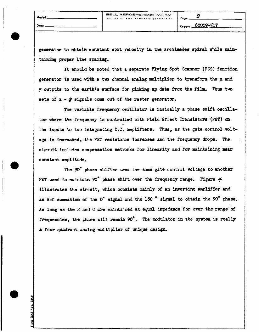
gemrater to obtain constant spot velocity in the Archimtdecl spiral while lepin-
taining proper line spacing.
It ahodd be noted that a separate Flying Spat Scanner (PSS) function
generatar 1s used tdth a trJ0 c h m d &og multiplier t0 %mnefcr~a the I: and
~r outputs to the earth's mwface far picklng up data f r o w the film. Thus two
seta of 1: - i signals c o w out of #e raster generatm.
The variable frequency oscillator is basically a phatae 8hift oscffla-
tor where the frerquency i a controlled With Fie ld Effect Tranelst~rs (FET) on
the tnptata to two intagrating D.C. amplifiers.
age i s facreaaad, the FisT reelstance Increasss and the frequency drops.
circuit +AGIW~US compensation networks for linearity and for maintaining near
canstPnt amplitude.
t
Thus, as the gate control volG
The
The 90' phase shifter uses the same gate control voltage t o another
FhT used t o maintain 90' phase s h i f t over the frequency rulge.
illustrates the cfrcnit , which consists mainly of an hmrtw amplifier and
an R-C sunmation of the 0' s l g n i l and the 180
As lcmg as the R and C a m maintained at equal hpdance for over the range of
fraquenciss, the phase vill renmh 90.. The =Mator in the systs3m is redly
a four quadrant analog ntultiplier of unique design,
Figure 4
signal to obtain the 90' phase.


L E y.
2
Date R. port eoooeP7
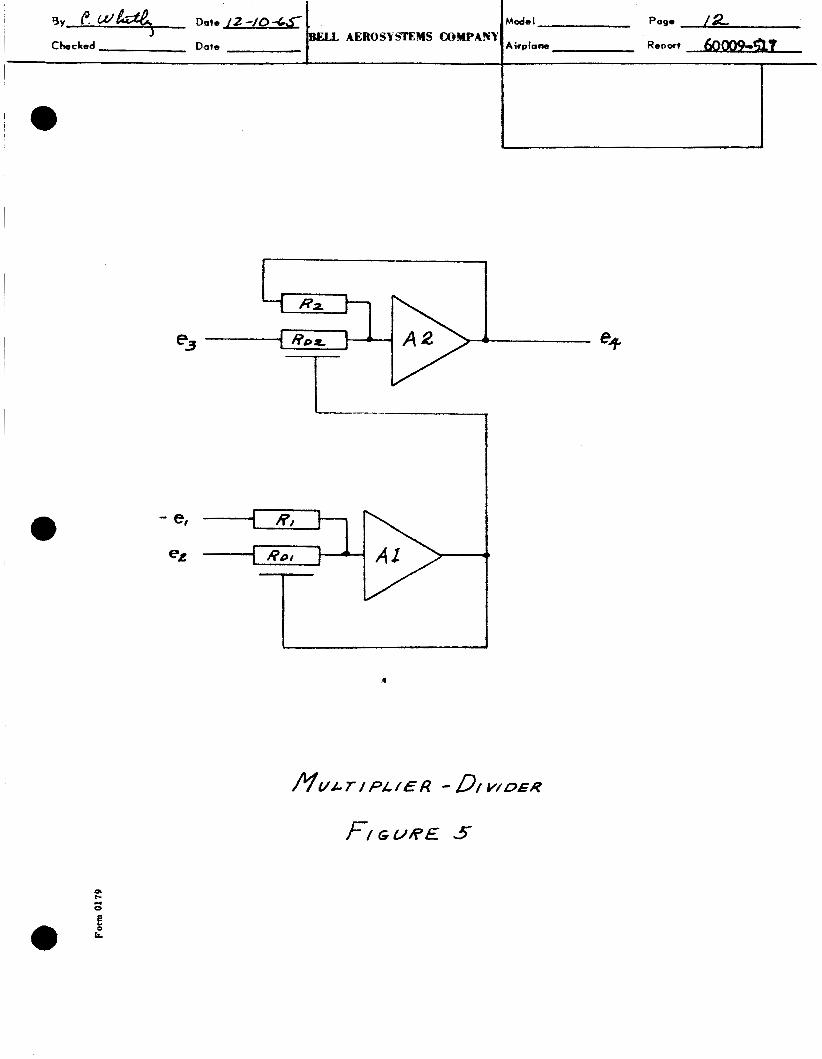
Figura shaws 8 geaeral block diagram of thia bTQ of device.
m when properly controlled (3 1 RD2 and matched
- %? "3
- RD2
Substituting ( 2 ) in (4) M ham
As a multiplier, 02 is held constant. Also an additlano1 offset is
lnasrted into the Plapllfier AT to o b t a i n four quadrant operation.
offset is subtracted o u t on the output of the lividor.
This D.C.
BY,%, Dote /t -/04.<
e3
, Mode I POgQ /a BELL AEROSYSTEYS COMPANY I Checked Dote
I Airpiom Report 6 a - C
7
I Dah
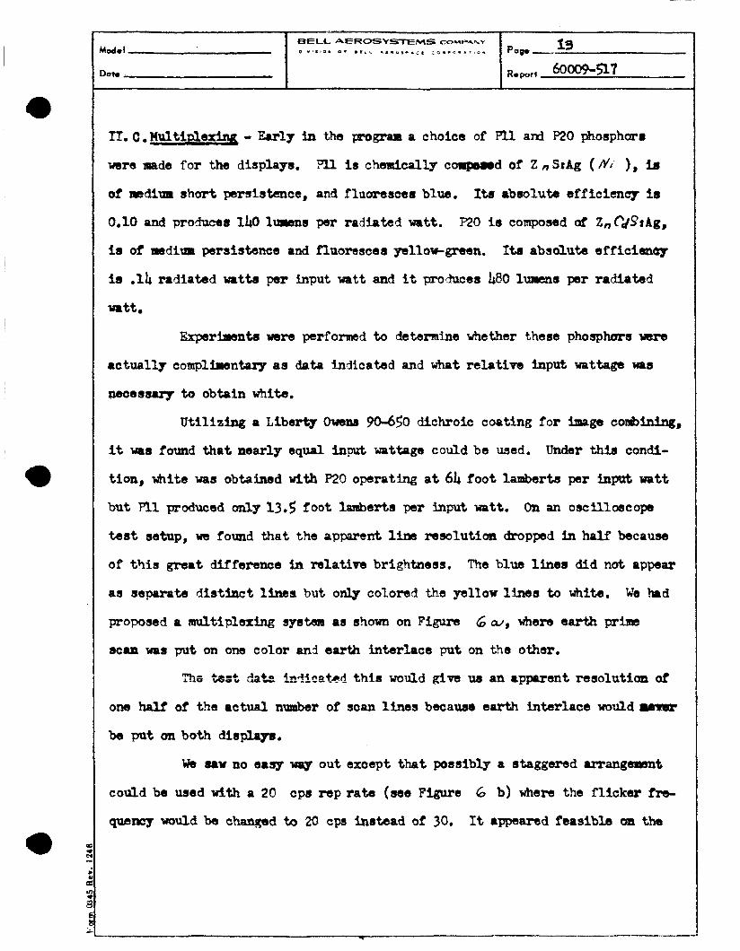
rI. c. H u l t i d k l q - Early in the program a choice of P l l ard P20 phosphor8
were made far the displays.
of sbdium short paraistence, and fluorsscsrs blue.
0.10 and produces 140 lumens per radiated watt.
is of aasdium persistence and fluoresces yellow-green.
is .14 radiated watts per input watt and it pmhces &BO lumens per radiated
watt
is cfiaraicpllp eorpewd of 2 n SzAg ( dl ), iS
Its absolutsr efffcimcy I s
p20 is composed of Z,pds’tAg,
Ita absolute efficis3uLp
Ekperiraanb were perfonnad to determine whether these phosphera were
actually complirsntorg a1 data indicated and what relativa b p u t wattage uas
WUa88U7 to obtain wfifb.
Utilizing a Liberty owbns 96-650 dichroic c o a t h e f o r Image co~&ln.ing,
it -8 found that nearly equal input wattage could be used, Undsr thb condi-
tion, whits was obtained w i t h P20 operating a t 64 foot Lambarts per input watt
but F l l podueed only 13.5 foot lanibarts per hput watt.
test setup, we found t h a t the apparent 1- ramlutian dropped in half because
of thia great dfffersnce In relative brightness.
as separato d i s t i n c t lints but only colored the yellow 1-s to white.
proposed a nmltlplaxlng s y s t m as shown on Figure
bcpa was put on one color an d earth interlace put on t!a other.
On an o a c i l l ~ c o p s
Tfie blue line8 did nat appear
We had
6 W , where earth p r b
mL- AIIO *&~t &+a th i s M u l d &vS UZI a r m e n t ~ S O l U t i ~ of
one hall of the actual number of scan lines becauss earth interlace w o l d w
be put an both disphyu.
wb mu no easy way out except that possibly a staggered pfiangmwnt
could be wed wlth a 20 cps rep rate (we Figure 6 b) where the f l i c k e r fra-
~ p s n c y would be changed ta 20 cps instead of 30. It appeared feasible 011 the


I 0
0 P-
i: 8 I
I ) .
1 1 . . --+--

I
e
a

The derivation is baaed an the
t
The design air wis that this frequency accurlng at l@, the maxi-
ma smplitpde capabiliv of the vldso BysteBI would pzvducre the requirsd rssolu-
ticme
caiE?mlatim of this*point to ths 3 bb point of the Sgsteoa anpli-
tade rtmptmse curve is difficult vlthout knowledge of the CUL'WI of IndiVidrral
arnplifian in the video chin.
to t b rise time characteristit of a d d e o chpin.
Row)vdr, an app-oxinste correlation can be mida
The transient rsspimse of a good video spstaa has dnimm over=
shoot er w#up. The transient response is shorn blow. If the as- aair
rpde that the 8irmsaiaPl responre above can bs appraxfnnted by the triana;rlar
responss shown, then the t e r m - t %a lof of the rise %!me. 1 2
I, m 18.8 L I ~ E I O ~
(IIC + - 10 x 18.8 188 nanom X 0.19 mdcrosec

e
0
a
a. The phatomltlplier noise dae to aigaal (this ia nut t i h a
sase aa dark current now).
b, pbasphor noise dub to &ranulur &wcture of' the tub0 sur2aae.
b theoretical signal to RHS mise ratio of thfrty to arm waa cal-
d a t e d . Previous experience s h m tht thi8 58 a goad qtlality phtzue.
A laboratosg pLK16'1 yo8 built a t MU us- the actual co?apomnte.
The flying spat wa8 tnv8rsed acros5 a ramr edge to obtain No fib wa8 wed,
vwiEicatian of plrrvlow calculation.

a. Rise t h e of 55 8180 under wny carefSlv controlled c m d . l t l o n ~ .
b. Riw tins of 96 aaaoseaond ander n o d al%gnmex& condlt16xu.
I


I , 1 1 I

MIRROR
i I
i I I

L
I I
-- .
I
/--- I

/
I i
Report 60009-517 j

I Doto

irar D.C. to 100 XC.
Checkout of the s p f r reresled several pram not anticimtad.
Firs-, the earth88 maptie f h l d serctrely rffmted registration 80 that a8
position of the displrfr ww altered, the reglabation ~ . b changed. This -t

crot for twa s\rcaersive 16 Billisscond
Qw paTiod and writing fn Iy)w intaraatlon during the mxt psriod,
the other tube fr erasing far

a
a
I
!
Doc, I
a
a
0
a
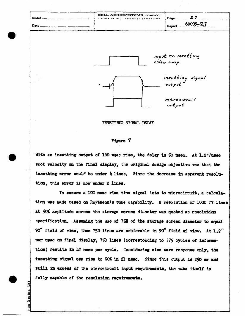
ChssrrcLtlan of the inmtttng hole on the earth atra in the f i n d
d f s p 4 showad a mll-defined, ahup insstting pattern Indicative of Mgh
r e s o l u ~ .
, . -\

a * L
I 1
n
E
!
Y
i
J


I kI*
.

u I
0 I-
-.( 0