r135 (e) 2004 - organisation internationale de … · ... of its member states. ... energy by...
TRANSCRIPT
Spectrophotometers for medical laboratories
Spectrophotomètres pour laboratoires médicaux
OIM
L R
135
Edi
tion
2004
(E)
OIML R 135Edition 2004 (E)
ORGANISATION INTERNATIONALE
DE MÉTROLOGIE LÉGALE
INTERNATIONAL ORGANIZATION
OF LEGAL METROLOGY
INTERNATIONAL
RECOMMENDATION
OIML R 135: 2004 (E)
2
Contents
Foreword ........................................................................................................................................................................... 3
1 Scope .................................................................................................................................................................... 4
2 Terminology .......................................................................................................................................................... 4
3 Description of the spectrophotometer ................................................................................................................ 8
4 General requirements ........................................................................................................................................ 10
5 Metrological requirements ................................................................................................................................ 11
6 Technical requirements ..................................................................................................................................... 12
7 Practical instructions ......................................................................................................................................... 13
8 Metrological controls ......................................................................................................................................... 13
Annex A Overall performance tests .......................................................................................................................... 15
Annex B Performance tests during disturbances .................................................................................................... 18
Annex C Test report format ...................................................................................................................................... 20
Annex D Outline of a certificate for type approval ................................................................................................. 46
Bibliography ................................................................................................................................................................... 47
OIML R 135: 2004 (E)
3
Foreword
The International Organization of Legal Metrology(OIML) is a worldwide, intergovernmental organizationwhose primary aim is to harmonize the regulations and
metrological controls applied by the national metrologicalservices, or related organizations, of its Member States.
The two main categories of OIML publications are:
• International Recommendations (OIML R), which aremodel regulations that establish the metrological charac-teristics required of certain measuring instruments andwhich specify methods and equipment for checking theirconformity; the OIML Member States shall implementthese Recommendations to the greatest possible extent;
• International Documents (OIML D), which are inform-ative in nature and intended to improve the work of themetrological services.
OIML Draft Recommendations and Documents are devel-oped by technical committees or subcommittees which areformed by the Member States. Certain international andregional institutions also participate on a consultation basis.
Cooperative agreements are established between OIML andcertain institutions, such as ISO and IEC, with the objective
of avoiding contradictory requirements; consequently, manu-facturers and users of measuring instruments, test labor-atories, etc. may apply simultaneously OIML publicationsand those of other institutions.
International Recommendations and International Docu-ments are published in French (F) and English (E) and aresubject to periodic revision.
This publication - reference OIML R 135, edition 2004 (E) -was developed by the OIML Technical Subcommittee TC 18/ SC 5 Measuring instruments for medical laboratories. Itwas approved for final publication by the InternationalCommittee of Legal Metrology in 2003 and will be submittedto the International Conference of Legal Metrology in 2004for formal sanction.
OIML publications may be obtained from the Organization’sheadquarters:
Bureau International de Métrologie Légale11, rue Turgot - 75009 Paris - FranceTelephone: 33 (0)1 48 78 12 82Fax: 33 (0)1 42 82 17 27E-mail: [email protected]: www.oiml.org
OIML R 135: 2004 (E)
4
1 Scope
This Recommendation provides requirements fordefining, testing and verifying the performance ofspectrophotometers used in clinical chemistrylaboratories to determine concentrations of analytes insamples of blood, serum, plasma, liquor cerebro-spinalis, urine, etc. derived from the human body bymeasuring the characteristic partial internal absorb-ances of prepared solutions in optical cells (cuvettes).
The major components specified in this Recom-mendation reflect the current technology and are notintended to preclude new developments.
The following are beyond the scope of thisRecommendation and are therefore not covered by it:
• Influences on the accuracy of measurement byautomated preparation and automated supply ofsamples;
• Sampling plans, sample preparations andmeasurement procedures for specific clinicalanalytes;
• Spectrophotometers at the development stage;• Spectrophotometers in bedside monitoring systems
and in self-checking monitoring systems; and• Reflection spectrometers and atomic absorption
spectrometers.
2 Terminology
For the purpose of this Recommendation, theTerminology below applies.
2.1 Absorption
Transformation of radiant energy to a different form ofenergy by interaction with matter. [ISO 6286, Table 1,No. 7]
2.2 Incident flux (φO)
Radiant luminous flux of the radiation striking anexternal surface of the medium. [ISO 6286, Table 1,No. 1]
Note: The coherent SI unit is the watt (W).
2.3 Transmitted flux (φtr)
Radiant luminous flux of the radiation emerging fromthe medium through an external surface which in theflux direction is opposite to the external surface of theflux incidence. [Adapted from ISO 6286, Table 1, No. 2]
Note: The coherent SI unit is the watt (W).
2.4 Transmittance (τ = φtr/φO)
Ratio of the transmitted radiant luminous flux to theincident flux. [ISO 6286, Table 1, No. 4]
Note: Transmittance has the dimension one and isexpressed with the derived coherent SI unit one(1).
2.5 Absorbance (A = lg(1/τ))
Logarithm to base ten of the reciprocal of thetransmittance. [ISO 6286, Table 1, No. 5]
Note: Absorbance has the dimension one and isexpressed with the derived coherent SI unitone (1).
2.6 Optical path length (b)
Distance covered by the radiation flux between theentry and exit surfaces of a solution contained in anoptical cell. [ISO 6286, Table 2, No. 13]
Note: The coherent SI unit is the metre (m), but thecentimetre (cm) or millimetre (mm) are usuallypreferred.
2.7 Amount of substance concentration (c)
Amount of substance of the compound dissolved,divided by the volume of the solution. [Adapted fromISO 6286, Table 2, No. 21.2]
Note: The coherent SI unit is the mole per cubic metre(mol/m3), but the mole per litre (mol/l, mol/L) orits subunits are often preferred.
Spectrophotometers for medical laboratories

OIML R 135: 2004 (E)
5
2.8 Specific molar absorption coefficient (ε = A/bc)
Absorbance divided by the optical pathlength b and theamount of substance concentration c.
Note 1: The derived SI unit is the square metre permole (1 m2/mol), but the litre per mole per mm(L/(mol ⋅ mm)) or litre per mole per cm(L/(mol ⋅ cm)) is often used.
Note 2: The specific molar absorption coefficient eslightly depends on the amount of substanceconcentration c.
2.9 Law of Bouguer-Lambert and Beer (A = lg (1/τ) = εbc)
Absorbance A is proportional to the optical pathlengthb and the amount of substance concentration c.
Note: Conditions for validity: A beam of parallelmonochromatic radiation traverses, at normalincidence, an absorbing medium with plane-parallel surfaces and which is homogeneous,isotropic, non-luminescent and non-scattering.[Adapted from ISO 6286, clause 3.3]
2.10 Sample flux (φs)
Radiant luminous flux of monochromatic radiationtransmitted by an optical cell containing the solutionon which the measurement is made and reaching thedetector. [ISO 6286, Table 2, No. 17]
Note: The coherent SI unit is the watt (W).
2.11 Reference flux (φr)
Radiant luminous flux of monochromatic radiationtransmitted by an optical cell containing the solutionused as reference and reaching the detector. [ISO 6286,Table 2, No. 16]
Note: The coherent SI unit is the watt (W).
2.12 Sample solution
Part of a fluid taken from a system and intended toprovide information about the properties of the system.
Note 1: The sample solution contains as a componentthe analyte and is applied to the sensor of ameasuring system and provides the outputsignal.
Note 2: In laboratory medicine the “system” usually isa subsystem of a patient such as blood orurine. [Adapted from [9], subclauses 4.114 and4.4]
2.13 Blank solution; reference solution
Solution similar to the sample solution but which doesnot contain the analyte.
Example: Solvent.
2.14 Calibration solution, standard solution
Solution of known concentration of the analyteproviding the independent variable of the calibrationfunction.
2.15 Intercomparison solution
Solution used in an external quality assessmentscheme. The assigned reference value of absorbance ofthis solution is known to the external qualityassessment scheme organizer only.
2.16 Reference material for absorbance
Material of sufficient homogeneous and well-established absorbance to be used for the calibration orcontrol of spectrophotometers.
Note: It may be in the form of a liquid or solid; forexample a glass filter. [Adapted from ISO Guide 30 andVIM, clause 6.13]
2.17 Certified reference material or absorbance
Reference material, accompanied by a certificate, thespectral absorbance of which is certified by aprocedure which establishes metrological traceabilityto a national or international standard of absorbance,and for which each certified quantity value isaccompanied by a measurement uncertainty at a statedlevel of confidence. [Adapted from ISO Guide 30 andVIM, clauses 6.1, 6.2, 6.3 and 6.14]
2.18 Characteristic partial internal absorbance Ac (Ac = lg(φr/φs) = εbc)
Fraction of the absorbance of the solution on which themeasurement is made due to a specified component.[Adapted from ISO 6286, Table 2, Nos. 19 and 20]

OIML R 135: 2004 (E)
6
Note 1: The characteristic partial internal absorbancehas the dimension one and is expressed withthe derived coherent SI unit one (1).
Note 2: The absorbance of the optical cell containingthis solution is corrected for. Conditions forvalidity: see 2.9.
2.19 Beer’s factor (Kε = εb = Ac/c)
Characteristic partial internal absorbance divided bythe amount of substance concentration of the analyte.The Beer’s factor is constant for specified experimentalconditions.
Note 1: The coherent SI unit is the cubic metre permole (m3/mol) but often the litre per mole(l/mol, L/mol) is preferred.
Note 2: For conditions of validity see 2.9.
2.20 Relative instrumental spectral function; detected radiant power spectrum
Function proportional to the product of the relativespectral distribution of the radiant energy, the relativespectral transmittance of all optical parts and therelative spectral sensitivity of the detector. [Adaptedfrom [5], clause 5]
Note: The relative instrumental spectral functiongenerally has different values for each particularwavelength.
2.21 Spectral width at half maximum value
Difference between a higher and lower wavelengthvalue at which the value of an optical quantity isreduced to half of its maximum value between the twowavelengths.
Note 1: The coherent SI unit is the metre (m), but oftenthe nanometre (nm) is used.
Note 2: The optical quantity can be e.g. radiantluminous flux, absorbance, etc.
2.22 Spectral width at one-hundredthmaximum value
Difference between a higher and lower wavelengthvalue at which the value of an optical quantity isreduced to 1/100 of its maximum value between thetwo wavelengths.
Note 1: The coherent SI unit is the metre (m), but oftenthe nanometre (nm) is used.
Note 2: The optical quantity can be e.g. radiantluminous flux, absorbance, etc.
2.23 False radiation fraction
Fraction of the signal recorded by the detector forradiation of all wavelengths outside the 1.01-fold of theone-hundredth value width out of the total signal at aparticular wavelength setting. [Adapted from [5],clause 5.3]
Note 1: The false radiation fraction has the dimensionone and is expressed with the derived coherentSI unit one (1).
Note 2: Radiation entering the spectrophotometerfrom the outside through leaks is not includedby this concept.
2.24 Catalytic activity
Property of a component corresponding to thecatalyzed substance rate of conversion of a specifiedchemical reaction in a specified measurement system.
Note 1: The coherent SI unit is the mole per second(mol/s), also called the “katal” (kat).
Note 2: Throughout this Recommendation the“component” is an enzyme.
Note 3: The quantity “catalytic activity” relates to anamount of active enzyme, not its concentration(see 2.25).
Note 4: The measurement procedure employingdefined indicator substance is an essentialelement for the definition of the measurand.
Note 5: In many instances, instead of the conversionrate of the substrate ascribed in the short nameof the enzyme analyte, e.g. “creatine kinase”,the conversion rate of an indicator substanceas substrate of a combined reaction, e.g.NADH, is measured. Then the measurandshould be defined as “catalytic activity of theenzyme as measured by the conversion rate ofan indicator substance in a specified systemaccording to a given measurement procedure”,e.g. “catalytic activity of creatine kinase asmeasured by the rate of conversion of NADH inthe IFCC reference procedure in humanserum”. [ISO 18153, clause 3.2]
2.25 Catalytic activity concentration; catalytic concentration
Catalytic activity of a component divided by the volumeof the original system.

OIML R 135: 2004 (E)
7
Note 1: The derived coherent SI unit is the mole persecond per cubic metre (mol/(s ⋅ m3)), alsocalled kat/m3. In laboratory medicine the moleper second per litre (mol/(s ⋅ L)) is also fre-quently used.
Note 2: Throughout this Recommendation the“component” is an enzyme and the “originalsystem” can be, e.g., the plasma of a bloodsample. [ISO/DIS 18153, clause 3.3]
2.26 Resolution of a spectrophotometer; resolving power of a spectrophotometer
Mean of the wavelength of two adjacent emission orabsorption lines, the signals of which are practicallystill separated by the spectrophotometer, divided by theabsolute wavelength difference of the two lines.
Note: Two equally strong emission lines are consideredas resolved, if the signal in the region betweenthe two maxima of the lines is reduced to at least80 % of the line’s maxima.
Two equally strong absorption lines are considered asresolved, if the extinction between the two maxima isreduced to at least 90 % of the line’s maxima. [Adaptedfrom [7], clause 4.5]
2.27 Error (of a measuring instrument)
Difference between the indication of a measuringinstrument (here a spectrophotometer) and a truevalue of the corresponding input quantity.
Note 1: Since a true value is indeterminable by nature,a conventional true value, i.e. an assignedvalue or best estimate of the value is used inpractice.
Note 2: For a material measure, the indication is thevalue assigned to it. [Adapted from VIM 5.20]
2.28 Intrinsic error
Error of a measuring instrument, determined underreference conditions.
Note: The initial intrinsic error is the intrinsic error ofa measuring instrument as determined prior toperformance tests and durability evaluations(see 2.32). [VIM 5.24]
2.29 Fault
Difference between the error and the intrinsic error ofa measuring instrument (here a spectrophotometer).[OIML D 11, 3.9]
2.30 Significant fault
Fault greater than the value specified in theappropriate Recommendation. [OIML D 11, 3.10]
2.31 Permanent automatic checking facility
Facility incorporated in a measuring instrument whichenables significant faults to be detected and acted uponand which operates on each measurement cyclewithout the intervention of the operator. [Adapted fromOIML D 11, 3.18 and 3.18.1]
2.32 Durability
Ability of a measuring instrument to maintain itsperformance characteristics over a stated period of use.[OIML D 11, 3.17]
2.33 Durability error
Difference between the intrinsic error over a period ofuse and the initial intrinsic error of a measuringinstrument. [OIML D 11, 3.11]
2.34 Significant durability error
Durability error greater than the value specified in theappropriate Recommendation. [OIML D 11, 3.12]
2.35 Durability protection facility
Facility that is incorporated in a measuring instrumentwhich enables the detection of and action uponsignificant durability errors. [OIML D 11, 3.19]
2.36 Maximum permissible error (of a measuring instrument); limits of permissible error (of a measuring instrument)
Extreme value of an error permitted by specifications,regulations, etc. for a given measuring instrument.[VIM, 5.21]
2.37 Calibration
Set of operations that establish, under specifiedconditions, the relationship between values ofquantities indicated by a measuring instrument or
OIML R 135: 2004 (E)
8
measuring system, or values represented by a materialmeasure or a reference material, and the corres-ponding values realized by standards.
Note 1: The result of a calibration permits either theassignment of values of measurands to theindications or the determination of correctionswith respect to indications.
Note 2: A calibration may also determine othermetrological properties such as the effect ofinfluence quantities.
Note 3: The result of a calibration may be recorded ina document, sometimes called a calibrationcertificate or a calibration report. [VIM, 6.11]
2.38 Type evaluation
Systematic examination and testing of the performanceof one or more samples of an identified type ofmeasuring instrument against documented require-ments, the results of which are contained in theevaluation report, in order to determine whether thetype may be approved.
Note: The term “pattern” is used in legal metrologywith the same meaning as “type”; below only theterm “type” is used. [VIML, 2.5]
2.39 Type approval
Decision of legal relevance, based on the evaluationreport, that the type of measuring instrument complieswith the relevant statutory requirements and is suitablefor use in the regulated area in such a way that it isexpected to provide reliable measurement results overa defined period of time. [VIML, 2.6]
2.40 Verification of a measuring instrument
Procedure other than type approval which includes theexamination and marking of a measuring instrumentand/or issuing of a verification certificate, thatestablishes and confirms that the measuringinstrument complies with the statutory requirements.[VIML, 2.13]
3 Description of the spectrophotometer
3.1 Principle
The principle of measurement by a spectrophotometeris the weakening of electromagnetic radiation bymutual interactions between the photons and theelectrons of the molecules during the passage througha medium. Because of the particular structure of itsmolecules, the absorbance of an analyte in a samplesolution is characteristic with respect to thewavelength of the radiation.
Absorbance is quantitatively described by the law ofBouguer-Lambert and Beer. The condition of itsapplication is the absence of scattering and reflectionin the solution and cuvette.
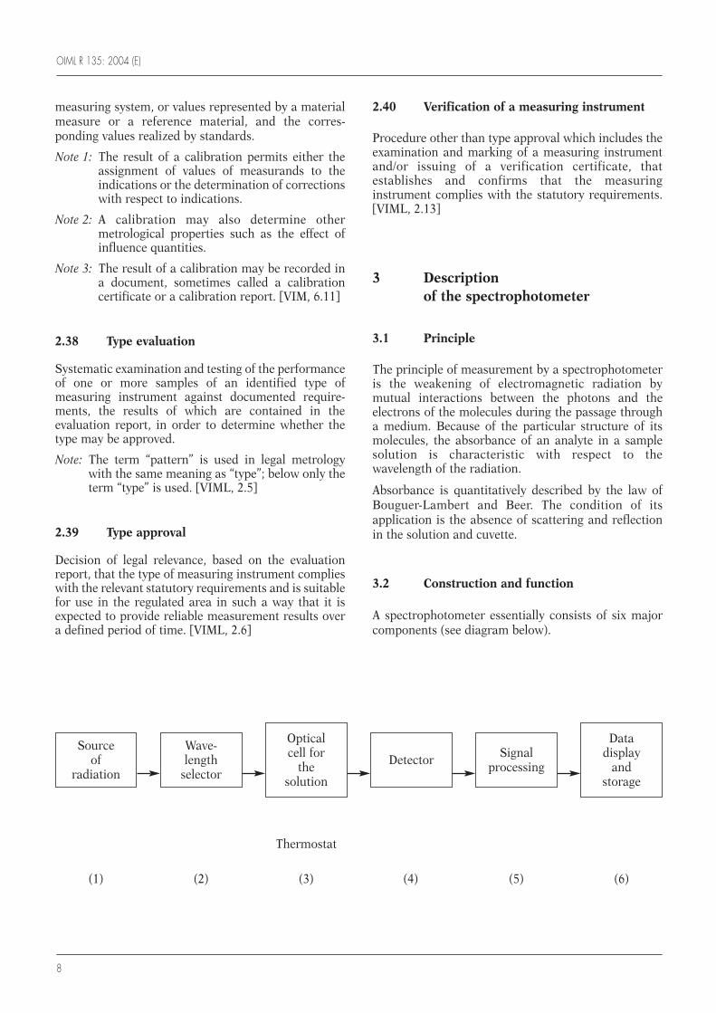
3.2 Construction and function
A spectrophotometer essentially consists of six majorcomponents (see diagram below).
Source of
radiation
Wave-length
selector
Optical cell for
the solution
Detector Signal processing
Data display
and storage
Thermostat
(1) (2) (3) (4) (5) (6)
OIML R 135: 2004 (E)
9
3.2.1 Source of radiation
Device that provides radiation.
Examples: Continuous spectra of radiation are emittedby tungsten filament lamps in the visible and nearinfrared ranges, and by deuterium lamps in the ultra-violet range. Line spectra are emitted by metal vaporlamps (Hg, Na, Cd, etc.).
Note: A spectrophotometer may be equipped with oneor more sources of radiation.
3.2.2 Wavelength selector
Device to isolate a wavelength interval of narrowbandwidth from the spectrum emitted by the radiationsource. There are three categories of wavelengthselectors:
• Specified bandpass selectors, realized by absorptionor interference filters;
• Selectors for continuous variation of wavelength(monochromators): prisms or gratings spatiallydecompose the spectrum of radiation, and a slitallows only a narrow region of wavelengths to pass.The combination of monochromator and slitwidthdetermines the spectral resolution;
• Selectors for the simultaneous measurement of alarge part of, or even the complete spectrum(polychromators): Here the optical cell precedes thewavelength selector. Prisms or gratings spatiallydecompose the spectrum of the transmitted flux andeach component of an array of several hundredphotodiodes selects and detects a narrow region ofwavelengths simultaneously with the other ones.
Complementary devices such as collimators, lenses,mirrors, diaphragms and slits give the radiation beamthe appropriate spatial definition, i.e. cross-section,parallelism, focus, path type (single or double beam),etc.
3.2.3 Optical cell (cuvette) to carry the solution
A transparent container for the solution ofmeasurement, which is traversed by the radiation flux.At the wavelengths of the measurement the optical cell(cuvette) should absorb as little radiation flux aspossible. The solution may be a sample, a reference ora calibration solution. Diluents and/or reagents may beadded to the solution.
Usually the radiation beam horizontally traverses thesolution in the optical cell. The distance between theinternal, plane, optical surfaces determines the opticalpath length for the solution. Different solutions may be
introduced into different optical cells or via a flow-through optical cell.
In another version the radiation beam traverses thesolution in the optical cell in the vertical direction. Inthat case, the optical path length is calculated from thevolume of the solution and the inner cross-sectionalarea of the optical cell. Numerous such optical cellsmay be combined to form a microplate.
The optical cell is supported and positioned by a carrierwhich may be mechanically operated.
The temperature of the optical cell may be regulated bya thermostat.
A housing of the optical cell keeps away the ambientlight.
For correction of the absorbances of the optical celland the reference solution (see 2.13) in single-beaminstruments, the sample flux is subsequently comparedwith the reference flux. In double-beam instruments,the comparison is carried out simultaneously using twooptical cells, each traversed by one of the two beams.
3.2.4 Detector
Device that is directly affected by flux of radiation,particularly transforming energy of the transmittedflux of radiation into electrical energy. Threephotoelectric effects can be employed as follows:• Photoemissive effect: phototubes, multiplier
phototubes;• Photoconductive effect: photoresistors;• Photovoltaic effect: non biased photodiodes
(photocells), biased photodiodes (also avalanchephotodiodes) and phototransistors.
A variable attenuator is used to match the intensity ofthe transmitted flux to the properties of the detector.
Double-beam instruments use either two separatedetectors or a single one, which alternately receives thetwo beams at a sufficiently high frequency.
In polychromator instruments, an array of severalhundred photodiodes or a charge coupled device (CCD)simultaneously detects a large part of, or even thecomplete spectrum of the transmitted flux of radiation.
3.2.5 Signal processing system
The signal furnished by the detector is amplified eitherby a DC amplifier or, if the flux is chopped by means ofelectromechanical, electronic or other devices, by anAC amplifier.
The amount of substance concentration value c of theanalyte is calculated from the signal.
OIML R 135: 2004 (E)
10
Examples: Supposing Beer’s factor Kε (2.19) isconstant,
a) The factor method yieldsc = Ac / Kε ,
b) The quotient method yieldsc = Ac cst / Ast and
c) The difference method yieldsc = cst + (Ac – Ast) / Kε ,
where:
Ac is the characteristic partial internal absorbance(2.18);
Ast is the absorbance of the standard solution (2.14);and
cst is the analyte amount of substance concentrationof the standard solution.
3.2.6 Data display and storage system
The data display and storage system presents andrecords the data of patient samples, calibrations andquality controls.
Usually the instrument is equipped with a standardinterface for personal computers.
3.2.7 Automation
Operation procedures of the spectrophotometer maybe more or less automated, with an internal or externalcomputer and appropriate appliances.
3.2.8 Permanent automatic checking facility
Checks components for significant faults, for examplethe electric current of the radiation source, the detectorvoltage, the temperature regulation or the automaticwashing of the cuvettes.
3.2.9 Durability protection feature
Checks individual components or assemblies of theinstrument for deterioration.
3.2.10 Time-dependent measurement methods
The catalyzed substance rate of conversion during aspecified chemical reaction is determined bymeasuring the time variation of the characteristicabsorbance of one of the substances involved. Fromthis time variation of the characteristic absorbance theconcentration of the analyte, which in most cases takes
part as a substrate or an effector, is calculated byapplication of known values of the specific molarabsorbance coefficient, the reaction rate constant (forthe kinetic method), the law of Bouguer-Lambert andBeer, the Michaelis-Menten equation, etc.
In the end-point method, the characteristic absorbanceof the indicating substance is measured twice: in theinitial state without the enzyme and in the end state,when the substrate is practically completely convertedby the enzyme. The reference solution can usually beomitted.
The kinetic method is suitable for first-order reactionsand pseudo-first-order reactions (the concentration ofthe co-reactant is considerably higher than that of thesubstrate to be determined) which are characterized byexponential concentration-time curves. Thecharacteristic absorbance of the indicating substance ismeasured twice during the reaction. The change of thischaracteristic absorbance in a fixed time interval isdirectly proportional to its initial amount of substanceconcentration for a given rate constant. Only a singlecalibrator solution is necessary. This “fixed-time”measurement method is especially suited forautomated light absorption spectrometers. Referencesolution and determination of the initial absorbancecan usually be omitted.
4 General requirements
4.1 Spectrophotometers for medical laboratoriesshall be designed and manufactured such that theirerrors of measurement do not exceed the maximumpermissible errors of measurement under ratedoperating conditions (see Table 1).
4.2 Spectrophotometers for medical laboratoriesshall be designed and manufactured such that whenthey are exposed to disturbances, significant faultseither do not occur, or are detected and reacted uponby means of a checking facility.
4.3 Spectrophotometers for medical laboratoriesshall be designed and manufactured such that after astated period of use, significant durability errors ofmeasurement either do not occur, or are detected andreacted upon by means of a durability protectionfeature.
4.4 Spectrophotometers for medical laboratoriesshall be designed and manufactured such that thepossibility of incorrect handling by personnel isminimized.
OIML R 135: 2004 (E)
11
4.5 The type of a spectrophotometer for medicallaboratories is considered to comply with theprovisions in 5.1, 5.2 and 5.3 if it successfully passesthe examination and tests specified in Annex A andAnnex B.
5 Metrological requirements
5.1 Rated operating conditions and reference conditions
The rated operating conditions and referenceconditions shall be as given in Table 1.
5.2 Limits of permissible errors and limit of false radiation fraction
5.2.1 The maximum permissible error ofwavelength selection under reference conditions shallbe 1 nm.
5.2.2 The maximum permissible error ofmeasurement of the characteristic partial internalabsorbance Ac under reference conditions shall be 0.03 Ac + 0.01.
5.2.3 The false radiation fraction shall not exceedthe value 0.02.
5.3 Requirements of durability
5.3.1 The durability of wavelength selection underreference conditions shall be such that after 24 hours
and 48 hours of use the maximum permissible errorindicated in 5.2.1 is not exceeded.
5.3.2 The durability of measurement of thecharacteristic partial internal absorbance Ac underreference conditions shall be such that after 24 hoursand 48 hours of use the maximum permissible errorindicated in 5.2.2 is not exceeded.
5.4 Measurement interval and resolution
5.4.1 The minimum interval of usable wavelengthsshall be 340 nm to 800 nm. Spectrophotometers withspecified bandpass selectors (filters) or with a linespectrum source of radiation shall discontinuouslycover at least this interval.
5.4.2 If the wavelength setting of thespectrophotometer is not continuously but onlygradually adjustable, the wavelength selection settingaccuracy shall be equal to or less than 1 nm. Thisrequirement is not applicable to spectrophotometerswith specified bandpass selectors (filters) or with a linespectrum source of radiation.
5.4.3 The minimum interval of absorbancemeasurement values shall be 0 to 2.
5.4.4 The resolution for the absorbance measure-ment shall be at least 200 or more.
5.5 Significant faults
Significant faults are faults whose values exceed thoseindicated in 5.2 (cf. also 2.30).
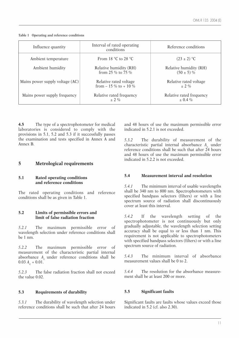
Table 1 Operating and reference conditions
Influence quantity Interval of rated operating Reference conditionsconditions
Ambient temperature From 18 °C to 28 °C (23 ± 2) °C
Ambient humidity Relative humidity (RH) Relative humidity (RH) from 25 % to 75 % (50 ± 5) %
Mains power supply voltage (AC) Relative rated voltage Relative rated voltage from – 15 % to + 10 % ± 2 %
Mains power supply frequency Relative rated frequency Relative rated frequency ± 2 % ± 0.4 %
OIML R 135: 2004 (E)
12
5.6 Performance tests under reference conditions
5.6.1 For type evaluation the entirespectrophotometer shall be tested under referenceconditions (5.1) with respect to:
• Error of wavelength selection;
• Error and linearity of absorbance measurementvalues;
• Spectral resolution of absorbance measurementvalues;
• False radiation fraction;
• Durability of absorbance measurement values.
5.6.2 The results of the tests specified in 5.6.1 shallmeet the applicable requirements of 5.2, 5.3, 5.4.2, and5.4.3.
5.7 Performance tests during disturbances
5.7.1 For type evaluation the entire spectro-photometer shall be tested under the appropriatereference conditions (5.1), while the followingdisturbances are consecutively and separately applied:
• Dry heat;
• Cold;
• Vibration (sinusoidal);
• Mechanical shock;
• Disturbance of AC power supply;
• Short-time power reduction;
• Bursts (transients);
• Electrostatic discharge; and
• Radiated, radio frequency, electromagnetic fields.
5.7.2 The results of the tests specified in 5.7.1 shallmeet the requirements of 4.2 and 5.2.2, respectively.
6 Technical requirements
6.1 In single-beam spectrophotometers, intensityfluctuations of the radiation source shall be avoided bya regulation circuit.
6.2 The resolution of the display device shallfulfill the resolution requirements for wavelengthselection (5.4.2) and absorbance measurement (5.4.4).
6.3 The warm-up time of the spectrophotometershall not exceed 15 minutes.
6.4 The response time of the spectrophotometershall not exceed 10 seconds.
Note: The response time is the time required fortransition from 10 % to 90 % of the stationarycharacteristic absorbance of an indicatorsubstance.
6.5 The expanded uncertainty (coverage factor 2;level of confidence 95 %) of the temperature regulationof the thermostat at the place(s) of the optical cell(s)(cuvette(s)) shall not exceed 0.5 K.
6.6 If the spectrophotometer includes accessoriesfor time-dependent measurement methods (see 3.2.10),the relative expanded uncertainty (coverage factor 2;level of confidence 95 %) of time interval measurementshall not exceed 3 % in the case of the end-pointmethod and 1 % in the case of the kinetic method.
6.7 If the spectrophotometer includes accessoriesfor time-dependent measurement methods (see 3.2.10),the time control shall cover at least the time intervalfrom 15 seconds to 10 minutes.
6.8 When the spectrophotometer is used forrecording absorption spectra, the relative expandeduncertainty (coverage factor 2; level of confidence95 %) of the base line position caused by electroniccomponents (zero line drift) shall not exceed 2 % of therespective ordinate range.
6.9 The spectrophotometer shall accept opticalcells (cuvettes) as currently used, especially rectangularcells with the optical path length 10 mm.
6.10 The spectrophotometer shall includechecking facilities. In the case of an automatedspectrophotometer, they shall work permanently andautomatically.
6.11 The spectrophotometer shall includedurability protection features. In the case of anautomated spectrophotometer, they shall workpermanently and automatically.
6.12 The marking on the spectrophotometer shallbe conspicuous and at least comprise the followingparticulars:• Name or trade mark of the manufacturer;• Model or type designation and serial number;
OIML R 135: 2004 (E)
13
• Power requirements; and• Safety requirements according to national
regulations.
7 Practical instructions
7.1 Manufacturers of spectrophotometers shallprovide an operating manual including the followinginformation:
a) Description of the scope of application;
b) Description of the function of the spectro-photometer;
c) Statement of the appropriate ambient conditionsfor use, storage, and transport of the spectro-photometer;
d) Identification of the rated operating conditions andreference conditions;
e) Identification of the maximum permissible errorfor wavelength selection;
f) Identification of the maximum permissible error ofabsorbance measurements;
g) Identification of the specified intervals ofwavelength selection and absorbance meas-urement;
h) Identification of the spectral half width atmaximum and of the spectral width at one-hundredth at maximum value for the specifiedinterval of wavelengths and, for spectro-photometers with specified bandpass selectors(filters), identification of the specific wavelengths;
Note: The requirements for the spectral half width atmaximum are specific to clinical application.
i) Description of appropriate use;
j) Instructions for the checking facilities and thedurability protection feature, including theprocedures for testing them;
k) Instructions for routine calibration procedures andschedules;
l) Instructions for routine maintenance proceduresand schedules;
m) Instructions on how to react upon faults;
n) Identification of the usable optical cells (cuvettes);
o) Identification of the computer interface;
p) Description of the software.
7.2 For spectrophotometers with specifiedbandpass selectors (filters) for specific wavelengths,the appropriate reference materials for executing theperformance tests according to the requirements ofthis Recommendation shall be supplied by themanufacturer of the spectrophotometer together withdescriptions and instructions for their use.
7.3 On request, the manufacturer ofspectrophotometers should provide specificinformation regarding the possibility of substandardperformance under the following conditions:
a) Outside the prescribed rated operating conditions;
b) After an accidental mechanical, electrical orthermal shock.
7.4 The accuracy of the wavelength selection andabsorbance measurement values has to be controlled atregular time intervals by measurements of standardsolutions, intercomparison solutions, referencematerials for absorbance and certified referencematerials for absorbance.
8 Metrological controls
Note: The tests shall be carried out by testing orverification laboratories that are acknowledgedeither for the OIML Certificate System or forother purposes according to the nationalregulations of the countries concerned.
8.1 Type evaluation
8.1.1 The documentation submitted by themanufacturers with the application for type approvalshall include the following information:
a) Description of the optical, mechanical, andelectrical principles of measurement;
b) Description of the technical design on the basis ofthe optical and electrical principles ofmeasurement;
c) Identification of the metrological and technicalperformances;
d) Description of how the tests for the checkingfacilities and the durability protection feature areto be carried out;
OIML R 135: 2004 (E)
14
e) Data and other information on performance testsand calibrations to determine whether the designof the spectrophotometer meets the requirementsof this Recommendation;
f) Operating manual (see 7.1).
8.1.2 The application for type approval shall beaccompanied by a document or other evidence to provethat the design and properties of the spectro-photometer comply with the requirements of thisRecommendation.
8.1.3 The documentation according to 8.1.1 and8.1.2 shall be evaluated, and especially the operatingmanual shall be reviewed for completeness and clarityof the operating instructions.
8.1.4 The test or verification laboratory shall carryout performance tests with respect to metrologicalrequirements described in section 5, particularly aslisted in 5.6 and 5.7 and described in Annexes A and B,or may accept the manufacturer’s test data to confirmacceptability of the performance.
8.1.5 The report on spectrophotometer testscarried out during type evaluation shall at least containthe information according to the format provided inAnnex D. A specific form may be developed accordingto national preferences. The manufacturer shall beprovided with specific comments on any test failures.
8.1.6 If the spectrophotometer meets all require-ments and successfully passes all tests for typeapproval, the testing or verification laboratory shallissue an approval certificate. The information to begiven in a certificate is outlined in Annex D.
8.2 Initial verification of any givenspectrophotometer
8.2.1 The verification laboratory shall examine theinformation provided by the manufacturer as specifiedin 8.1.
8.2.2 The verification laboratory shall examine thespectrophotometer’s type approval certificate and themanufacturer’s marking.
8.2.3 For initial verification the entirespectrophotometer shall be tested as described inAnnex A under reference conditions (5.1) with respectto:• Error of wavelength selection;• Error and linearity of absorbance measurement
values;• False radiation fraction.
8.2.4 The laboratory shall provide a verifiedspectrophotometer with an external verification markwhich indicates conformity with the provisions of thisRecommendation. Additional verification marks shallbe attached to protect the optical system and, ifnecessary, other elements of the spectrophotometeragainst modification or alteration after verification.
8.2.5 The laboratory shall indicate the period ofvalidity of the verification.
8.2.6 A spectrophotometer shall undergosubsequent verification after repair or replacement ofcomponent parts or units of its electrical control andreadout system.

OIML R 135: 2004 (E)
15
A.1 The objective of these tests is to verifycompliance with the requirements of 4.1 and 5.6 bymeasuring the following performance characteristicsof a spectrophotometer for medical laboratories:• Error of wavelength selection;• Error and linearity of absorbance measurement
values;• Spectral resolution of absorbance measurement
values;• False radiation fraction;• Reproducibility error of absorbance measurement
values.
A.2 The tests shall be carried out under referenceconditions (5.1) with various certified reference filtersfor absorbance on the intact light absorptionspectrometer. Dismantling of the spectrophotometerfor the test is generally not intended.
The certified reference filters shall be used incombination with their matching reference filters. Thereference values of the certified reference filters aretaken as assigned values. In order to justify this, theexpanded uncertainty (coverage factor 2; level ofconfidence 95 %) of the reference values of the certifiedreference filters shall not exceed one third of themaximum permissible errors indicated in 5.2.1 and5.2.2.
Note: The preservation of the certified reference filtersincludes periodic calibration, storage undersuitable conditions and maintenance.
A.3 To test whether any single measurementvalue fulfills the respective requirements of 5.2, asample test according to an ISO statistical method shallbe executed with a certain number of measurementvalues. The values of the test measurements areassumed to be random and independent samplemembers of a normally distributed population. To meetthe measurement deviation requirement, a two-sidedstatistical tolerance interval, calculated from the valuesof the test measurements, shall fit into the interval ofthe reference value minus and plus the maximum
permissible error of any single measurement value asgiven in 5.2. In other words, the two followinginequations shall be fulfilled:
x– + ks ≤ xref + e,
x– – ks ≥ xref – e,
where:
x– = n
Σi=l
xi / n is the sample average;
xi is the value of a samplemember;
n is the sample size;
k is the tolerance limit factor;
s =
√n
Σi=l
(xi – x–)2 /(n – 1) is the sample standarddeviation (SD);
xref is the assigned referencevalue of the certifiedreference filter;
e is the maximum permissibleerror.
The requirement of maximum permissible error of anysingle measurement value given in 5.2 is assumed to becomplied with if both of the two inequalities arefulfilled.
International Standard ISO 3207, Table 8, [10] liststolerance limit factors for the construction of two-sidedstatistical tolerance intervals when the true populationaverage and the true standard deviation are not known.
For the purpose of this Recommendation the tolerancelimit factor k shall be based on the fixed probability(level of confidence) p = 0.95, i.e. the statisticaltolerance interval will contain at least the proportionp = 0.95 of the population of measurement values.
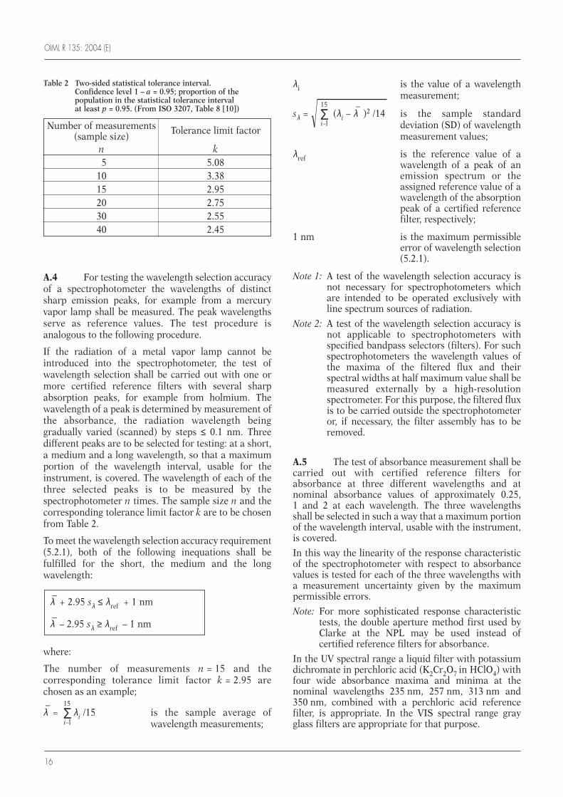
A sample size of n = 15 is recommended, so that k = 2.95 follows for the tolerance limit factor. Othernumbers of measurements, as given in Table 2, may beselected; then the corresponding values of k shall beused.
Annex A
Overall performance tests
(Mandatory)
OIML R 135: 2004 (E)
16
A.4 For testing the wavelength selection accuracyof a spectrophotometer the wavelengths of distinctsharp emission peaks, for example from a mercuryvapor lamp shall be measured. The peak wavelengthsserve as reference values. The test procedure isanalogous to the following procedure.
If the radiation of a metal vapor lamp cannot beintroduced into the spectrophotometer, the test ofwavelength selection shall be carried out with one ormore certified reference filters with several sharpabsorption peaks, for example from holmium. Thewavelength of a peak is determined by measurement ofthe absorbance, the radiation wavelength beinggradually varied (scanned) by steps ≤ 0.1 nm. Threedifferent peaks are to be selected for testing: at a short,a medium and a long wavelength, so that a maximumportion of the wavelength interval, usable for theinstrument, is covered. The wavelength of each of thethree selected peaks is to be measured by thespectrophotometer n times. The sample size n and thecorresponding tolerance limit factor k are to be chosenfrom Table 2.
To meet the wavelength selection accuracy requirement(5.2.1), both of the following inequations shall befulfilled for the short, the medium and the longwavelength:
where:
The number of measurements n = 15 and thecorresponding tolerance limit factor k = 2.95 arechosen as an example;
λ–
= 15
Σi–l
λi /15 is the sample average ofwavelength measurements;
λ–
+ 2.95 sλ ≤ λref + 1 nm
λ–
– 2.95 sλ ≥ λref – 1 nm
λi is the value of a wavelengthmeasurement;
sλ =
√15
Σi–l
(λi – λ–
)2 /14 is the sample standarddeviation (SD) of wavelengthmeasurement values;
λref is the reference value of awavelength of a peak of anemission spectrum or theassigned reference value of awavelength of the absorptionpeak of a certified referencefilter, respectively;
1 nm is the maximum permissibleerror of wavelength selection(5.2.1).
Note 1: A test of the wavelength selection accuracy isnot necessary for spectrophotometers whichare intended to be operated exclusively withline spectrum sources of radiation.
Note 2: A test of the wavelength selection accuracy isnot applicable to spectrophotometers withspecified bandpass selectors (filters). For suchspectrophotometers the wavelength values ofthe maxima of the filtered flux and theirspectral widths at half maximum value shall bemeasured externally by a high-resolutionspectrometer. For this purpose, the filtered fluxis to be carried outside the spectrophotometeror, if necessary, the filter assembly has to beremoved.
A.5 The test of absorbance measurement shall becarried out with certified reference filters forabsorbance at three different wavelengths and atnominal absorbance values of approximately 0.25, 1 and 2 at each wavelength. The three wavelengthsshall be selected in such a way that a maximum portionof the wavelength interval, usable with the instrument,is covered.
In this way the linearity of the response characteristicof the spectrophotometer with respect to absorbancevalues is tested for each of the three wavelengths witha measurement uncertainty given by the maximumpermissible errors.
Note: For more sophisticated response characteristictests, the double aperture method first used byClarke at the NPL may be used instead ofcertified reference filters for absorbance.
In the UV spectral range a liquid filter with potassiumdichromate in perchloric acid (K2Cr2O7 in HClO4) withfour wide absorbance maxima and minima at thenominal wavelengths 235 nm, 257 nm, 313 nm and350 nm, combined with a perchloric acid referencefilter, is appropriate. In the VIS spectral range grayglass filters are appropriate for that purpose.
Table 2 Two-sided statistical tolerance interval. Confidence level 1 – a = 0.95; proportion of thepopulation in the statistical tolerance interval at least p = 0.95. (From ISO 3207, Table 8 [10])
Number of measurements Tolerance limit factor (sample size)
n k5 5.08
10 3.3815 2.9520 2.7530 2.5540 2.45
OIML R 135: 2004 (E)
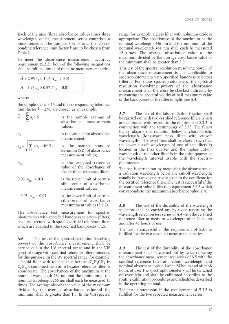
17
Each of the nine (three absorbance values times threewavelength values) measurement series comprises nmeasurements. The sample size n and the corres-ponding tolerance limit factor k are to be chosen fromTable 2.
To meet the absorbance measurement accuracyrequirement (5.2.2), both of the following inequationsshall be fulfilled for all of the nine measurement series:
where:
the sample size n = 15 and the corresponding tolerancelimit factor k = 2.95 are chosen as an example;
A–
= 15
Σi–l
Ai /15 is the sample average ofabsorbance measurementvalues;
Ai is the value of an absorbancemeasurement;
sA =
√15
Σi–l
(Ai – A–)2 /14 is the sample standard
deviation (SD) of absorbancemeasurement values;
Aref is the assigned referencevalue of the absorbance ofthe certified reference filters;
0.03 Aref + 0.01 is the upper limit of permis-sible error of absorbancemeasurement values;
– 0.03 Aref – 0.01 is the lower limit of permis-sible error of absorbancemeasurement values (5.2.2).
The absorbance test measurement for spectro-photometers with specified bandpass selectors (filters)shall be executed with special certified reference filterswhich are adapted to the specified bandpasses (7.2).
A.6 The test of the spectral resolution (resolvingpower) of the absorbance measurement shall becarried out in the UV spectral range and in the VISspectral range with certified reference filters intendedfor this purpose. In the UV spectral range, for example,a liquid filter with toluene in n-hexane (C6H5CH3 inC6H14), combined with an n-hexane reference filter, isappropriate. The absorbances of the maximum at thenominal wavelength 269 nm and the minimum at thenominal wavelength 266 nm shall each be measured 15times. The average absorbance value of the maximumdivided by the average absorbance value of theminimum shall be greater than 1.5. In the VIS spectral
Α–
+ 2.95 sA ≤ 1.03 Aref + 0.01
Α–
– 2.95 sA ≥ 0.97 Aref – 0.01
range, for example, a glass filter with holmium oxide isappropriate. The absorbance of the maximum at thenominal wavelength 446 nm and the minimum at thenominal wavelength 451 nm shall each be measured15 times. The average absorbance value of themaximum divided by the average absorbance value ofthe minimum shall be greater than 3.0.
This test of the spectral resolution (resolving power) ofthe absorbance measurement is not applicable tospectrophotometers with specified bandpass selectors(filters). For these spectrophotometers, the spectralresolution (resolving power) of the absorbancemeasurement shall therefore be checked indirectly bymeasuring the spectral widths of half maximum valueof the bandpasses of the filtered light; see A.4.
A.7 The test of the false radiation fraction shallbe carried out with two certified reference filters whichare calibrated with respect to the requirement 5.2.3 inconjunction with the terminology of 2.23. The filtershighly absorb the radiation below a characteristicwavelength (long-wave pass filter with cut-offwavelength). The two filters shall be chosen such thatthe lower cut-off wavelength of one of the filters islocated in the first quarter and the higher cut-offwavelength of the other filter is in the third quarter ofthe wavelength interval usable with the spectro-photometer.
The test is carried out by measuring the absorbance ata radiation wavelength below the cut-off wavelength;usually both wavelengths are given in the certificate forthe certified reference filter. The test is successful if themeasurement value fulfils the requirement 5.2.3 whichcorresponds to the minimum absorbance value 1.70.
A.8 The test of the durability of the wavelengthselection shall be carried out by twice repeating thewavelength selection test series of A.4 with the certifiedreference filter at medium wavelength after 24 hoursand after 48 hours of use.
The test is successful if the requirement of 5.3.1 isfulfilled for the two repeated measurement series.
A.9 The test of the durability of the absorbancemeasurement shall be carried out by twice repeatingthe absorbance measurement test series of A.5 with thecertified reference filter at medium wavelength andnominal absorbance value 1 after 24 hours and after 48hours of use. The spectrophotometer shall be switchedoff overnight and shall be calibrated according to theroutine calibration procedures and schedules describedin the operating manual.
The test is successful if the requirement of 5.3.2 isfulfilled for the two repeated measurement series.
OIML R 135: 2004 (E)
18
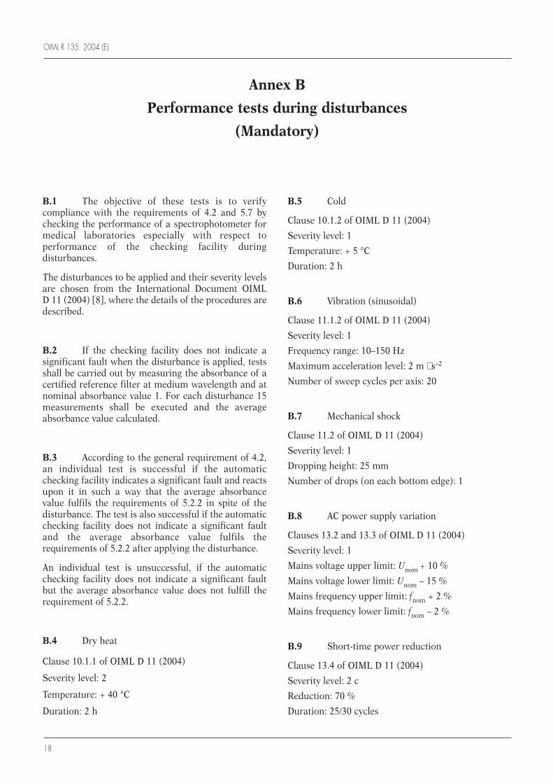
B.1 The objective of these tests is to verifycompliance with the requirements of 4.2 and 5.7 bychecking the performance of a spectrophotometer formedical laboratories especially with respect toperformance of the checking facility duringdisturbances.
The disturbances to be applied and their severity levelsare chosen from the International Document OIMLD 11 (2004) [8], where the details of the procedures aredescribed.
B.2 If the checking facility does not indicate asignificant fault when the disturbance is applied, testsshall be carried out by measuring the absorbance of acertified reference filter at medium wavelength and atnominal absorbance value 1. For each disturbance 15measurements shall be executed and the averageabsorbance value calculated.
B.3 According to the general requirement of 4.2,an individual test is successful if the automaticchecking facility indicates a significant fault and reactsupon it in such a way that the average absorbancevalue fulfils the requirements of 5.2.2 in spite of thedisturbance. The test is also successful if the automaticchecking facility does not indicate a significant faultand the average absorbance value fulfils therequirements of 5.2.2 after applying the disturbance.
An individual test is unsuccessful, if the automaticchecking facility does not indicate a significant faultbut the average absorbance value does not fulfill therequirement of 5.2.2.
B.4 Dry heat
Clause 10.1.1 of OIML D 11 (2004)
Severity level: 2
Temperature: + 40 °C
Duration: 2 h
B.5 Cold
Clause 10.1.2 of OIML D 11 (2004)
Severity level: 1
Temperature: + 5 °C
Duration: 2 h
B.6 Vibration (sinusoidal)
Clause 11.1.2 of OIML D 11 (2004)
Severity level: 1
Frequency range: 10–150 Hz
Maximum acceleration level: 2 m ⋅ s–2
Number of sweep cycles per axis: 20
B.7 Mechanical shock
Clause 11.2 of OIML D 11 (2004)
Severity level: 1
Dropping height: 25 mm
Number of drops (on each bottom edge): 1
B.8 AC power supply variation
Clauses 13.2 and 13.3 of OIML D 11 (2004)
Severity level: 1
Mains voltage upper limit: Unom + 10 %
Mains voltage lower limit: Unom – 15 %
Mains frequency upper limit: fnom + 2 %
Mains frequency lower limit: fnom – 2 %
B.9 Short-time power reduction
Clause 13.4 of OIML D 11 (2004)
Severity level: 2 c
Reduction: 70 %
Duration: 25/30 cycles
Annex B
Performance tests during disturbances
(Mandatory)
OIML R 135: 2004 (E)
19
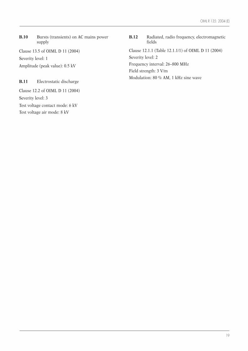
B.10 Bursts (transients) on AC mains powersupply
Clause 13.5 of OIML D 11 (2004)
Severity level: 1
Amplitude (peak value): 0.5 kV
B.11 Electrostatic discharge
Clause 12.2 of OIML D 11 (2004)
Severity level: 3
Test voltage contact mode: 6 kV
Test voltage air mode: 8 kV
B.12 Radiated, radio frequency, electromagneticfields
Clause 12.1.1 (Table 12.1.1/1) of OIML D 11 (2004)
Severity level: 2
Frequency interval: 26–800 MHz
Field strength: 3 V/m
Modulation: 80 % AM, 1 kHz sine wave

OIML R 135: 2004 (E)
20
Explanatory notes to the Test report format
i) General
This Test report format, which is informative with regard to the implementation of OIML Recommendation R 135in national regulations, presents a standardized format for the results of the various tests and examinations to whicha type of a spectrophotometer for medical use shall be submitted with a view to its approval.
It is recommended that all metrology services or laboratories evaluating types of spectrophotometers according toOIML R 135 or to national or regional regulations based on OIML R 135 use this Test report format, directly or aftertranslation into a language other than English or French.
It is also recommended that this Test report format in English or French (or in both languages) be transmitted bythe country performing the tests to the relevant authorities of another country, under bi- or multilateral cooperationagreements.
In the framework of the OIML Certificate System for Measuring Instruments, use of the Test report format ismandatory.
ii) Page numbering
In addition to the sequential numbering at the bottom of each page, a space has been left at the top of each page(starting on page 21) for numbering the pages of the reports established following this model. In particular each testis reported individually on a separate page following the relevant format.
For a given report it is advisable to complete the sequential numbering of each page by indicating the total numberof pages in the report.
Annex C
Test report format
(Mandatory for application within the OIML Certificate System for Measuring Instruments)
Report page …/… OIML R 135: 2004 (E)
21
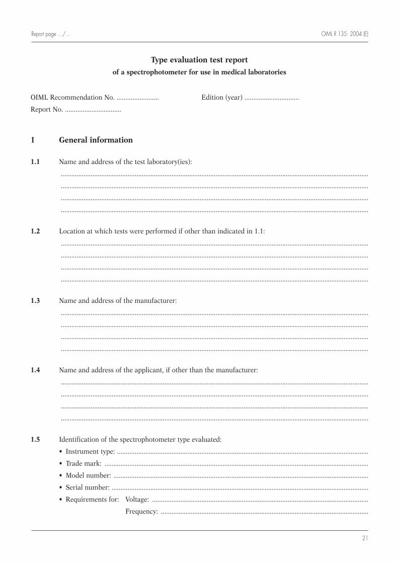
Type evaluation test report
of a spectrophotometer for use in medical laboratories
OIML Recommendation No. ........................ Edition (year) ...............................
Report No. ................................
1 General information
1.1 Name and address of the test laboratory(ies):
...............................................................................................................................................................................
...............................................................................................................................................................................
...............................................................................................................................................................................
...............................................................................................................................................................................
1.2 Location at which tests were performed if other than indicated in 1.1:
...............................................................................................................................................................................
...............................................................................................................................................................................
...............................................................................................................................................................................
...............................................................................................................................................................................
1.3 Name and address of the manufacturer:
...............................................................................................................................................................................
...............................................................................................................................................................................
...............................................................................................................................................................................
...............................................................................................................................................................................
1.4 Name and address of the applicant, if other than the manufacturer:
...............................................................................................................................................................................
...............................................................................................................................................................................
...............................................................................................................................................................................
...............................................................................................................................................................................
1.5 Identification of the spectrophotometer type evaluated:
• Instrument type: ...............................................................................................................................................
• Trade mark: ......................................................................................................................................................
• Model number: .................................................................................................................................................
• Serial number: ..................................................................................................................................................
• Requirements for: Voltage: ...........................................................................................................................
Frequency: ......................................................................................................................

OIML R 135: 2004 (E) Report page …/…
22
1.6 Review of the operating manual: Acceptable m Deficient m
Comments: ...........................................................................................................................................................
...............................................................................................................................................................................
...............................................................................................................................................................................
...............................................................................................................................................................................
...............................................................................................................................................................................
2 Summary of the information in the operating manual and visual inspection
2.1 Rated operating conditions; intervals:
Ambient temperature: from ............ °C to ............ °C
Ambient humidity: from ............ % RH to ............ % RH
Mains power supply voltage (AC): ............ V, range from .......... V to .......... V
Mains power supply frequency: ............ Hz, range from .......... Hz to .......... Hz
Comments: ...........................................................................................................................................................
...............................................................................................................................................................................
...............................................................................................................................................................................
...............................................................................................................................................................................
...............................................................................................................................................................................
2.2 Interval of usable wavelength selection: from ............... nm to ............... nm
Comments: ...........................................................................................................................................................
...............................................................................................................................................................................
...............................................................................................................................................................................
...............................................................................................................................................................................
...............................................................................................................................................................................
2.3 Resolution of wavelength selection: ................ nm
Comments: ...........................................................................................................................................................
...............................................................................................................................................................................
...............................................................................................................................................................................
...............................................................................................................................................................................
...............................................................................................................................................................................
2.4 Interval of absorbance measurement: from ................. to ...................
Comments: ...........................................................................................................................................................
...............................................................................................................................................................................
...............................................................................................................................................................................
...............................................................................................................................................................................
...............................................................................................................................................................................
Report page …/… OIML R 135: 2004 (E)
23
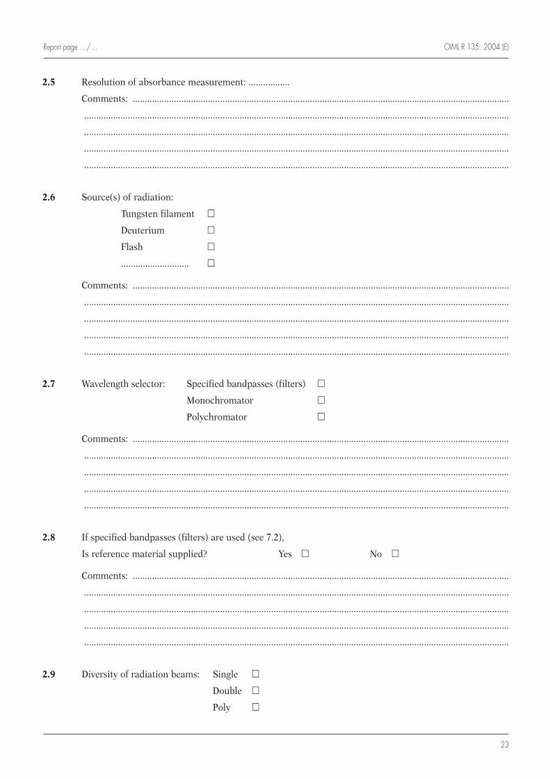
2.5 Resolution of absorbance measurement: .................
Comments: ...........................................................................................................................................................
...............................................................................................................................................................................
...............................................................................................................................................................................
...............................................................................................................................................................................
...............................................................................................................................................................................
2.6 Source(s) of radiation:
Tungsten filament m
Deuterium m
Flash m
............................ m
Comments: ...........................................................................................................................................................
...............................................................................................................................................................................
...............................................................................................................................................................................
...............................................................................................................................................................................
...............................................................................................................................................................................
2.7 Wavelength selector: Specified bandpasses (filters) m
Monochromator m
Polychromator m
Comments: ...........................................................................................................................................................
...............................................................................................................................................................................
...............................................................................................................................................................................
...............................................................................................................................................................................
...............................................................................................................................................................................
2.8 If specified bandpasses (filters) are used (see 7.2),
Is reference material supplied? Yes m No m
Comments: ...........................................................................................................................................................
...............................................................................................................................................................................
...............................................................................................................................................................................
...............................................................................................................................................................................
...............................................................................................................................................................................
2.9 Diversity of radiation beams: Single m
Double m
Poly m
OIML R 135: 2004 (E) Report page …/…
24
Comments: ...........................................................................................................................................................
...............................................................................................................................................................................
...............................................................................................................................................................................
...............................................................................................................................................................................
...............................................................................................................................................................................
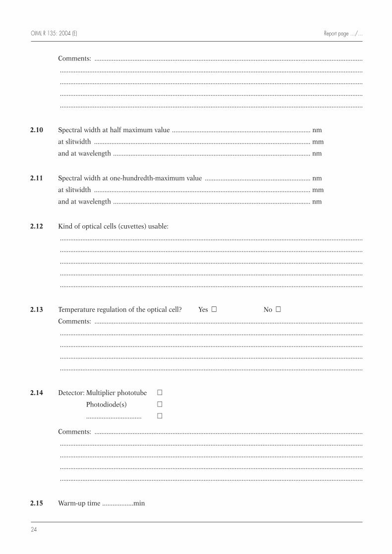
2.10 Spectral width at half maximum value ................................................................................ nm
at slitwidth ............................................................................................................................. mm
and at wavelength .................................................................................................................. nm
2.11 Spectral width at one-hundredth-maximum value ............................................................. nm
at slitwidth ............................................................................................................................. mm
and at wavelength .................................................................................................................. nm
2.12 Kind of optical cells (cuvettes) usable:
...............................................................................................................................................................................
...............................................................................................................................................................................
...............................................................................................................................................................................
...............................................................................................................................................................................
...............................................................................................................................................................................
2.13 Temperature regulation of the optical cell? Yes m No m
Comments: ...........................................................................................................................................................
...............................................................................................................................................................................
...............................................................................................................................................................................
...............................................................................................................................................................................
...............................................................................................................................................................................
2.14 Detector: Multiplier phototube m
Photodiode(s) m
................................ m
Comments: ...........................................................................................................................................................
...............................................................................................................................................................................
...............................................................................................................................................................................
...............................................................................................................................................................................
...............................................................................................................................................................................
2.15 Warm-up time ..................min
Report page …/… OIML R 135: 2004 (E)
25
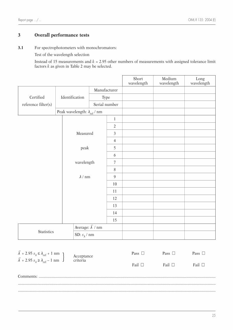
3 Overall performance tests
3.1 For spectrophotometers with monochromators:
Test of the wavelength selection
Instead of 15 measurements and k = 2.95 other numbers of measurements with assigned tolerance limitfactors k as given in Table 2 may be selected.
λ–
+ 2.95 sλ ≤ λref + 1 nmAcceptance
Pass m Pass m Pass m
λ–
+ 2.95 sλ ≥ λref – 1 nm } criteriaFail m Fail m Fail m
Comments: ............................................................................................................................................................................
................................................................................................................................................................................................
................................................................................................................................................................................................
Short Medium Long wavelength wavelength wavelength
Manufacturer
Certified Identification Type
reference filter(s) Serial number
Peak wavelength: λref / nm
1
2
Measured 3
4
peak 5
6
wavelength 7
8
λ / nm 9
10
11
12
13
14
15
StatisticsAverage: λ
–/ nm
SD: sλ / nm
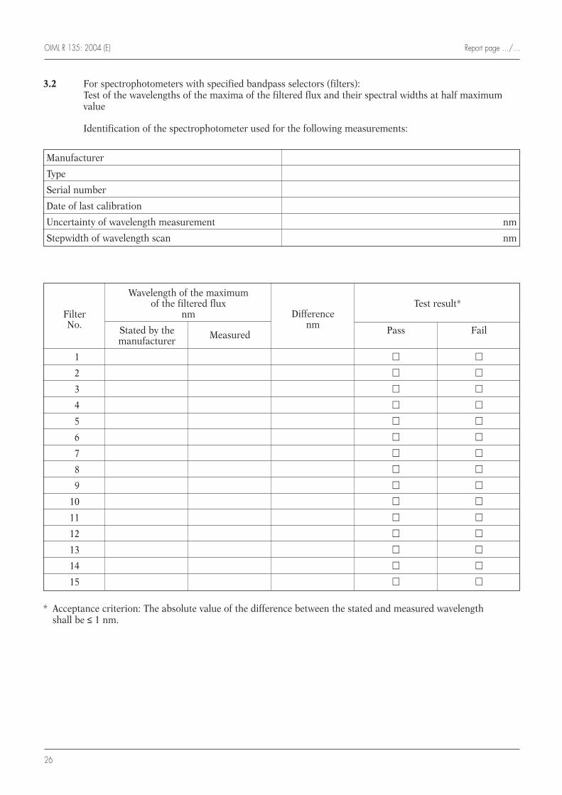
OIML R 135: 2004 (E) Report page …/…
26
3.2 For spectrophotometers with specified bandpass selectors (filters): Test of the wavelengths of the maxima of the filtered flux and their spectral widths at half maximumvalue
Identification of the spectrophotometer used for the following measurements:
* Acceptance criterion: The absolute value of the difference between the stated and measured wavelength shall be ≤ 1 nm.
Manufacturer
Type
Serial number
Date of last calibration
Uncertainty of wavelength measurement nm
Stepwidth of wavelength scan nm
Wavelength of the maximum of the filtered flux
DifferenceTest result*
Filter nmnmNo. Stated by the Measured Pass Fail
manufacturer
1 m m
2 m m
3 m m
4 m m
5 m m
6 m m
7 m m
8 m m
9 m m
10 m m
11 m m
12 m m
13 m m
14 m m
15 m m
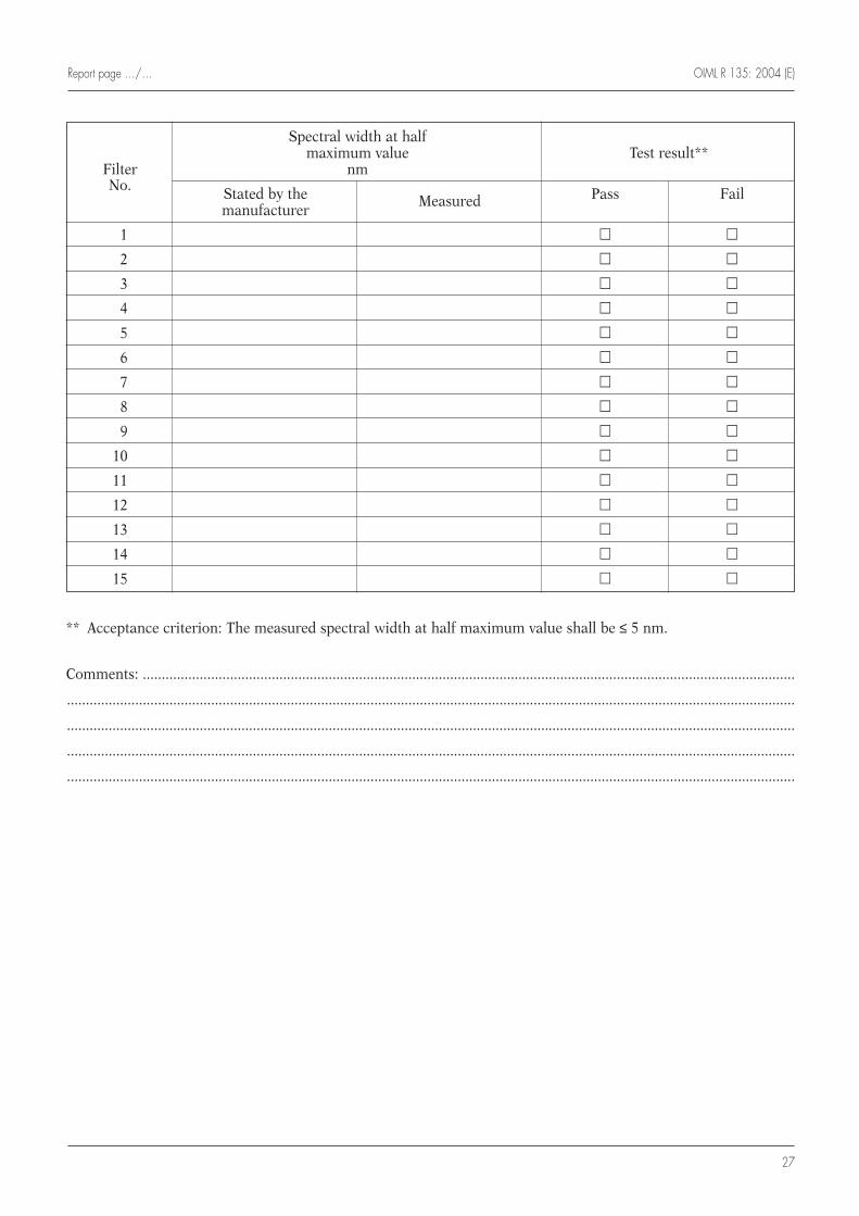
Report page …/… OIML R 135: 2004 (E)
27
** Acceptance criterion: The measured spectral width at half maximum value shall be ≤ 5 nm.
Comments: ............................................................................................................................................................................
................................................................................................................................................................................................
................................................................................................................................................................................................
................................................................................................................................................................................................
................................................................................................................................................................................................
Spectral width at half maximum value Test result**
Filter nmNo. Stated by the Measured Pass Fail
manufacturer
1 m m
2 m m
3 m m
4 m m
5 m m
6 m m
7 m m
8 m m
9 m m
10 m m
11 m m
12 m m
13 m m
14 m m
15 m m
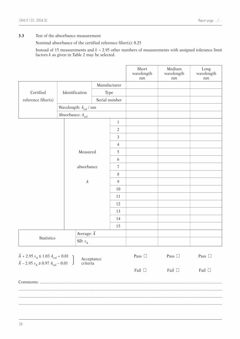
OIML R 135: 2004 (E) Report page …/…
28
3.3 Test of the absorbance measurement
Nominal absorbance of the certified reference filter(s): 0.25
Instead of 15 measurements and k = 2.95 other numbers of measurements with assigned tolerance limitfactors k as given in Table 2 may be selected.
A– + 2.95 sA ≤ 1.03 Aref + 0.01Acceptance
Pass m Pass m Pass m
A– – 2.95 sA ≥ 0.97 Aref – 0.01 } criteria
Fail m Fail m Fail m
Comments: ............................................................................................................................................................................
................................................................................................................................................................................................
................................................................................................................................................................................................
................................................................................................................................................................................................
Short Medium Long wavelength wavelength wavelength
nm nm nm
Manufacturer
Certified Identification Type
reference filter(s) Serial number
Wavelength: λref / nm
Absorbance: Aref
1
2
3
4
Measured 5
6
absorbance 7
8
A 9
10
11
12
13
14
15
StatisticsAverage: A–
SD: sA

Report page …/… OIML R 135: 2004 (E)
29
3.4 Test of the absorbance measurement
Nominal absorbance of the certified reference filter(s): 1
Instead of 15 measurements and k = 2.95 other numbers of measurements with assigned tolerance limitfactors k as given in Table 2 may be selected.
A– + 2.95 sA ≤ 1.03 Aref + 0.01Acceptance
Pass m Pass m Pass m
A– – 2.95 sA ≥ 0.97 Aref – 0.01 } criteria
Fail m Fail m Fail m
Comments: ............................................................................................................................................................................
................................................................................................................................................................................................
................................................................................................................................................................................................
................................................................................................................................................................................................
Short Medium Long wavelength wavelength wavelength
nm nm nm
Manufacturer
Certified Identification Type
reference filter(s) Serial number
Wavelength: λref / nm
Absorbance: Aref
1
2
3
4
Measured 5
6
absorbance 7
8
A 9
10
11
12
13
14
15
StatisticsAverage: A–
SD: sA

OIML R 135: 2004 (E) Report page …/…
30
3.5 Test of the absorbance measurement
Nominal absorbance of the certified reference filter(s): 2
Instead of 15 measurements and k = 2.95 other numbers of measurements with assigned tolerance limitfactors k as given in Table 2 may be selected.
A– + 2.95 sA ≤ 1.03 Aref + 0.01Acceptance
Pass m Pass m Pass m
A– – 2.95 sA ≥ 0.97 Aref – 0.01 } criteria
Fail m Fail m Fail m
Comments: ............................................................................................................................................................................
................................................................................................................................................................................................
................................................................................................................................................................................................
................................................................................................................................................................................................
Short Medium Long wavelength wavelength wavelength
nm nm nm
Manufacturer
Certified Identification Type
reference filter(s) Serial number
Wavelength: λref / nm
Absorbance: Aref
1
2
3
4
Measured 5
6
absorbance 7
8
A 9
10
11
12
13
14
15
StatisticsAverage: A–
SD: sA
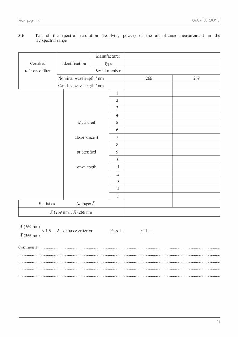
Report page …/… OIML R 135: 2004 (E)
31
3.6 Test of the spectral resolution (resolving power) of the absorbance measurement in the UV spectral range
A– (269 nm)—————— > 1.5 Acceptance criterion Pass m Fail mA– (266 nm)
Comments: ............................................................................................................................................................................
................................................................................................................................................................................................
................................................................................................................................................................................................
................................................................................................................................................................................................
................................................................................................................................................................................................
Manufacturer
Certified Identification Type
reference filter Serial number
Nominal wavelength / nm 266 269
Certified wavelength / nm
1
2
3
4
Measured 5
6
absorbance A 7
8
at certified 9
10
wavelength 11
12
13
14
15
Statistics Average: A–
A– (269 nm) / A– (266 nm)
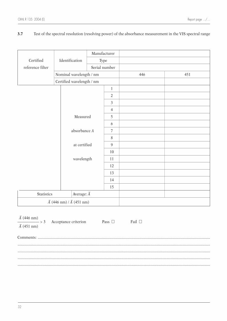
OIML R 135: 2004 (E) Report page …/…
32
3.7 Test of the spectral resolution (resolving power) of the absorbance measurement in the VIS spectral range
A– (446 nm)—————— > 3 Acceptance criterion Pass m Fail mA– (451 nm)
Comments: ............................................................................................................................................................................
................................................................................................................................................................................................
................................................................................................................................................................................................
................................................................................................................................................................................................
................................................................................................................................................................................................
Manufacturer
Certified Identification Type
reference filter Serial number
Nominal wavelength / nm 446 451
Certified wavelength / nm
1
2
3
4
Measured 5
6
absorbance A 7
8
at certified 9
10
wavelength 11
12
13
14
15
Statistics Average: A–
A– (446 nm) / A– (451 nm)
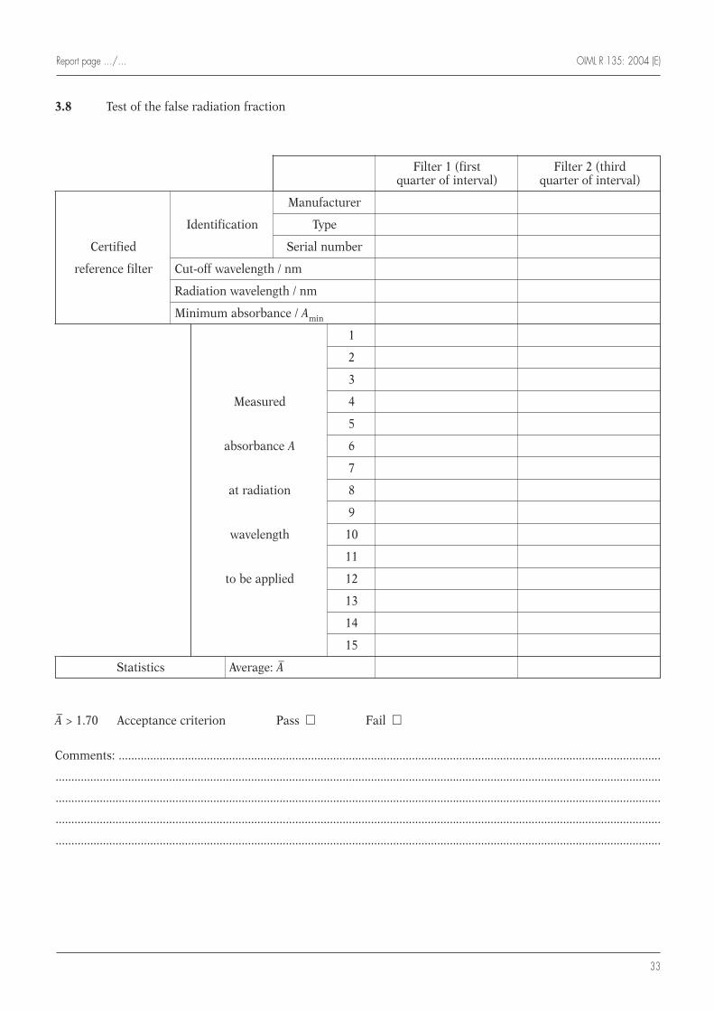
Report page …/… OIML R 135: 2004 (E)
33
3.8 Test of the false radiation fraction
A– > 1.70 Acceptance criterion Pass m Fail m
Comments: ............................................................................................................................................................................
................................................................................................................................................................................................
................................................................................................................................................................................................
................................................................................................................................................................................................
................................................................................................................................................................................................
Filter 1 (first Filter 2 (third quarter of interval) quarter of interval)
Manufacturer
Identification Type
Certified Serial number
reference filter Cut-off wavelength / nm
Radiation wavelength / nm
Minimum absorbance / Amin
1
2
3
Measured 4
5
absorbance A 6
7
at radiation 8
9
wavelength 10
11
to be applied 12
13
14
15
Statistics Average: A–
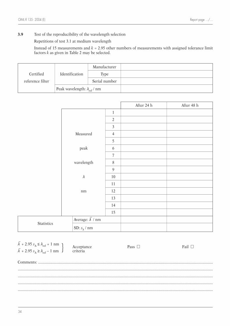
OIML R 135: 2004 (E) Report page …/…
34
3.9 Test of the reproducibility of the wavelength selection
Repetitions of test 3.1 at medium wavelength
Instead of 15 measurements and k = 2.95 other numbers of measurements with assigned tolerance limitfactors k as given in Table 2 may be selected.
λ–
+ 2.95 sA ≤ λref + 1 nmAcceptance Pass m Fail m
λ–
+ 2.95 sA ≥ λref – 1 nm } criteria
Comments: ............................................................................................................................................................................
................................................................................................................................................................................................
................................................................................................................................................................................................
................................................................................................................................................................................................
................................................................................................................................................................................................
Manufacturer
Certified Identification Type
reference filter Serial number
Peak wavelength: λref / nm
After 24 h After 48 h
1
2
3
Measured 4
5
peak 6
7
wavelength 8
9
λ 10
11
nm 12
13
14
15
StatisticsAverage: λ
–/ nm
SD: sλ / nm
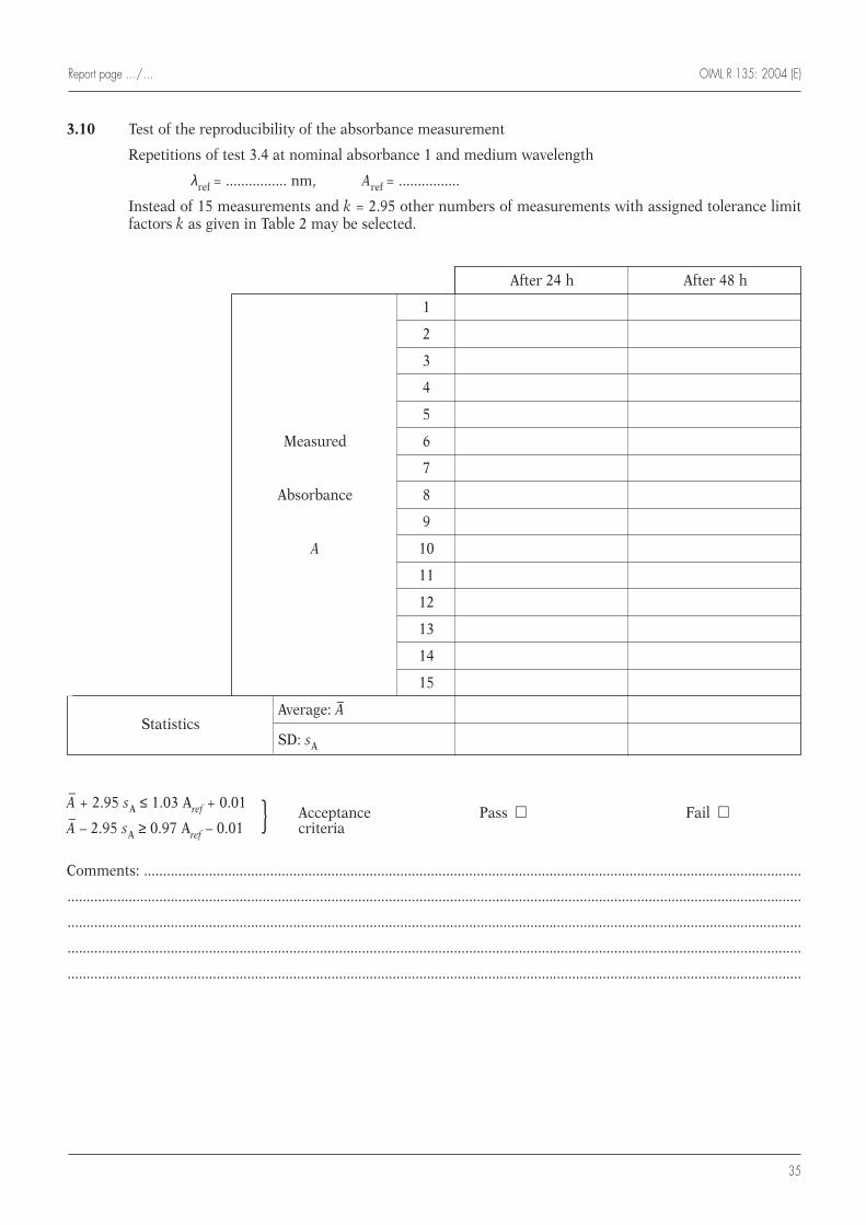
Report page …/… OIML R 135: 2004 (E)
35
3.10 Test of the reproducibility of the absorbance measurement
Repetitions of test 3.4 at nominal absorbance 1 and medium wavelength
λref = ................ nm, Aref = ................
Instead of 15 measurements and k = 2.95 other numbers of measurements with assigned tolerance limitfactors k as given in Table 2 may be selected.
A–
+ 2.95 sA ≤ 1.03 Aref + 0.01Acceptance Pass m Fail m
A–
– 2.95 sA ≥ 0.97 Aref – 0.01 } criteria
Comments: ............................................................................................................................................................................
................................................................................................................................................................................................
................................................................................................................................................................................................
................................................................................................................................................................................................
................................................................................................................................................................................................
After 24 h After 48 h
1
2
3
4
5
Measured 6
7
Absorbance 8
9
A 10
11
12
13
14
15
StatisticsAverage: A–
SD: sA

OIML R 135: 2004 (E) Report page …/…
36
4 Performance tests during disturbances
Instead of 15 measurements and k = 2.95 other numbers of measurements with assigned tolerance limitfactors k as given in Table 2 may be selected.
4.1 Identification of the certified reference filter used for the following absorbance measurements duringdisturbances. (Repetitions of test 3.4 at nominal absorbance value 1 and medium wavelength)
4.2 Test of the absorbance measurement during the disturbance: Dry heat
Clause 10.1.1 of OIML D 11
Severity level: 2; Temperature: + 40 °C; Duration: 2 h
The automatic checking facility indicates significant fault: Yes m No m
If “No”, measure 15 absorbance values A:
Statistics: Average: A– = ............., SD: sA = .................
A–
+ 2.95 sA ≤ 1.03 Aref + 0.01Acceptance Pass m Fail m
A–
– 2.95 sA ≥ 0.97 Aref – 0.01 } criteria
Comments: ............................................................................................................................................................................
................................................................................................................................................................................................
................................................................................................................................................................................................
................................................................................................................................................................................................
................................................................................................................................................................................................
Manufacturer
Type
Serial number
Certified wavelength λref used / nm
Certified absorbance Aref at the wavelength λref
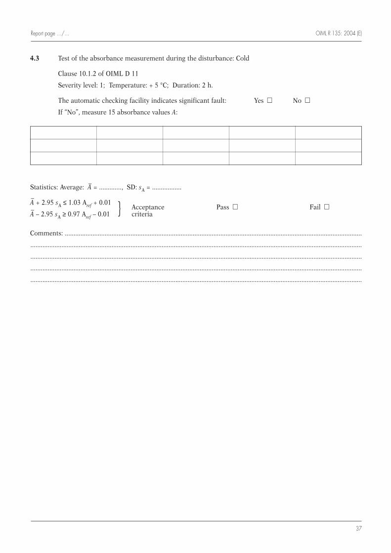
Report page …/… OIML R 135: 2004 (E)
37
4.3 Test of the absorbance measurement during the disturbance: Cold
Clause 10.1.2 of OIML D 11
Severity level: 1; Temperature: + 5 °C; Duration: 2 h.
The automatic checking facility indicates significant fault: Yes m No m
If “No”, measure 15 absorbance values A:
Statistics: Average: A– = ............., SD: sA = .................
A–
+ 2.95 sA ≤ 1.03 Aref + 0.01Acceptance Pass m Fail m
A–
– 2.95 sA ≥ 0.97 Aref – 0.01 } criteria
Comments: ............................................................................................................................................................................
................................................................................................................................................................................................
................................................................................................................................................................................................
................................................................................................................................................................................................
................................................................................................................................................................................................
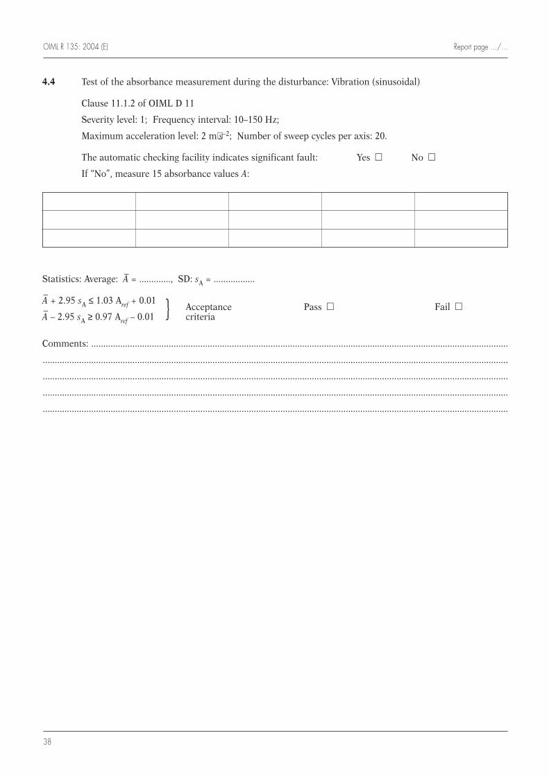
OIML R 135: 2004 (E) Report page …/…
38
4.4 Test of the absorbance measurement during the disturbance: Vibration (sinusoidal)
Clause 11.1.2 of OIML D 11
Severity level: 1; Frequency interval: 10–150 Hz;
Maximum acceleration level: 2 m⋅s–2; Number of sweep cycles per axis: 20.
The automatic checking facility indicates significant fault: Yes m No m
If “No”, measure 15 absorbance values A:
Statistics: Average: A– = ............., SD: sA = .................
A–
+ 2.95 sA ≤ 1.03 Aref + 0.01Acceptance Pass m Fail m
A–
– 2.95 sA ≥ 0.97 Aref – 0.01 } criteria
Comments: ............................................................................................................................................................................
................................................................................................................................................................................................
................................................................................................................................................................................................
................................................................................................................................................................................................
................................................................................................................................................................................................
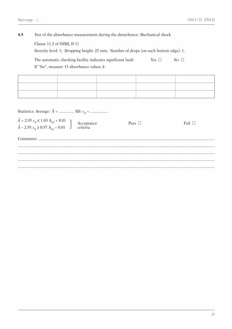
Report page …/… OIML R 135: 2004 (E)
39
4.5 Test of the absorbance measurement during the disturbance: Mechanical shock
Clause 11.2 of OIML D 11
Severity level: 1; Dropping height: 25 mm; Number of drops (on each bottom edge): 1.
The automatic checking facility indicates significant fault: Yes m No m
If “No”, measure 15 absorbance values A:
Statistics: Average: A– = ............., SD: sA = .................
A–
+ 2.95 sA ≤ 1.03 Aref + 0.01Acceptance Pass m Fail m
A–
– 2.95 sA ≥ 0.97 Aref – 0.01 } criteria
Comments: ............................................................................................................................................................................
................................................................................................................................................................................................
................................................................................................................................................................................................
................................................................................................................................................................................................
................................................................................................................................................................................................
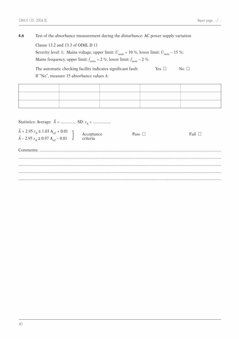
OIML R 135: 2004 (E) Report page …/…
40
4.6 Test of the absorbance measurement during the disturbance: AC power supply variation
Clause 13.2 and 13.3 of OIML D 11
Severity level: 1; Mains voltage, upper limit: Unom + 10 %, lower limit: Unom – 15 %;
Mains frequency, upper limit: fnom + 2 %, lower limit: fnom – 2 %.
The automatic checking facility indicates significant fault: Yes m No m
If “No”, measure 15 absorbance values A:
Statistics: Average: A– = ............., SD: sA = .................
A–
+ 2.95 sA ≤ 1.03 Aref + 0.01Acceptance Pass m Fail m
A–
– 2.95 sA ≥ 0.97 Aref – 0.01 } criteria
Comments: ............................................................................................................................................................................
................................................................................................................................................................................................
................................................................................................................................................................................................
................................................................................................................................................................................................
................................................................................................................................................................................................
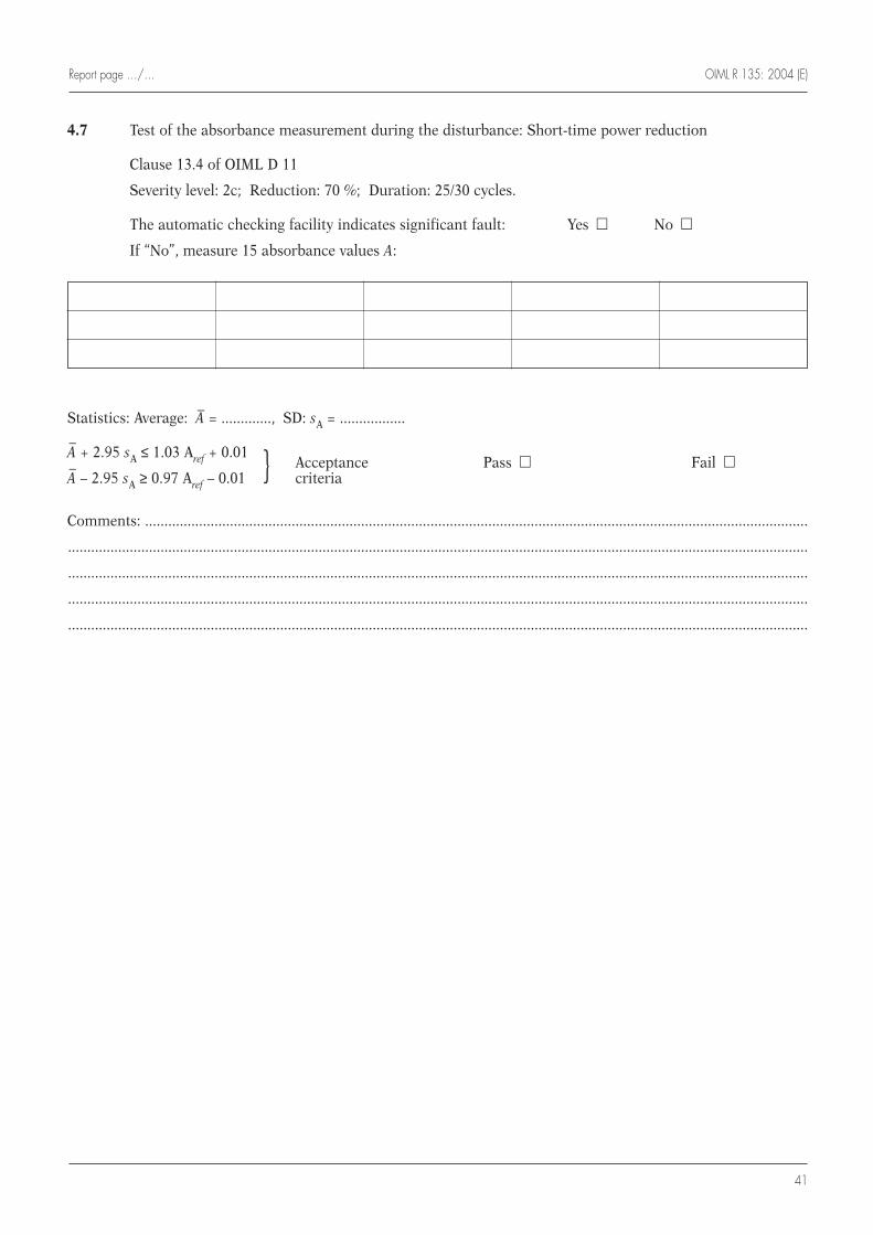
Report page …/… OIML R 135: 2004 (E)
41
4.7 Test of the absorbance measurement during the disturbance: Short-time power reduction
Clause 13.4 of OIML D 11
Severity level: 2c; Reduction: 70 %; Duration: 25/30 cycles.
The automatic checking facility indicates significant fault: Yes m No m
If “No”, measure 15 absorbance values A:
Statistics: Average: A– = ............., SD: sA = .................
A–
+ 2.95 sA ≤ 1.03 Aref + 0.01Acceptance Pass m Fail m
A–
– 2.95 sA ≥ 0.97 Aref – 0.01 } criteria
Comments: ............................................................................................................................................................................
................................................................................................................................................................................................
................................................................................................................................................................................................
................................................................................................................................................................................................
................................................................................................................................................................................................
OIML R 135: 2004 (E) Report page …/…
42
4.8 Test of the absorbance measurement during the disturbance: Bursts (transients) on AC mains powersupply
Clause 13.5 of OIML D 11
Severity level: 1; Amplitude (peak value): 0.5 kV.
The automatic checking facility indicates significant fault: Yes m No m
If “No”, measure 15 absorbance values A:
Statistics: Average: A– = ............., SD: sA = .................
A–
+ 2.95 sA ≤ 1.03 Aref + 0.01Acceptance Pass m Fail m
A–
– 2.95 sA ≥ 0.97 Aref – 0.01 } criteria
Comments: ............................................................................................................................................................................
................................................................................................................................................................................................
................................................................................................................................................................................................
................................................................................................................................................................................................
................................................................................................................................................................................................
Report page …/… OIML R 135: 2004 (E)
43
4.9 Test of the absorbance measurement during the disturbance: Electrostatic discharge
Clause 12.2 of OIML D 11
Severity level: 3; Test voltage: contact mode: 6 kV; air mode: 8 kV.
The automatic checking facility indicates significant fault: Yes m No m
If “No”, measure 15 absorbance values A:
Statistics: Average: A– = ............., SD: sA = .................
A–
+ 2.95 sA ≤ 1.03 Aref + 0.01Acceptance Pass m Fail m
A–
– 2.95 sA ≥ 0.97 Aref – 0.01 } criteria
Comments: ............................................................................................................................................................................
................................................................................................................................................................................................
................................................................................................................................................................................................
................................................................................................................................................................................................
................................................................................................................................................................................................
OIML R 135: 2004 (E) Report page …/…
44
4.10 Test of the absorbance measurement during the disturbance: Radiated, radio frequency, electromagneticfields
Clause 12.1 (Table 12.1.1/1) of OIML D 11
Severity level: 2; Frequency range: 26–800 MHz; Field strength: 3 V/m; Modulation: 80 % AM, 1 kHz sine wave.
The automatic checking facility indicates significant fault: Yes m No m
If “No”, measure 15 absorbance values A:
Statistics: Average: A– = ............., SD: sA = .................
A–
+ 2.95 sA ≤ 1.03 Aref + 0.01Acceptance Pass m Fail m
A–
– 2.95 sA ≥ 0.97 Aref – 0.01 } criteria
Comments: ............................................................................................................................................................................
................................................................................................................................................................................................
................................................................................................................................................................................................
................................................................................................................................................................................................
................................................................................................................................................................................................
Report page …/… OIML R 135: 2004 (E)
45
5 Brief statement of the conclusions as to whether the spectrophotometer tested meetsthe requirements of this Recommendation
................................................................................................................................................................................................
................................................................................................................................................................................................
................................................................................................................................................................................................
................................................................................................................................................................................................
6 Person(s) responsible for the testing
Name: ...................................................................................................................................................................
Title: ......................................................................................................................................................................
Signature: .............................................................................................................................................................
Date: ......................................................................................................................................................................
OIML R 135: 2004 (E)
46
Annex D
Outline of a certificate for type approval
(Informative)
D.1 Name and address of manufacturer or distributor:
...............................................................................................................................................................................
...............................................................................................................................................................................
...............................................................................................................................................................................
...............................................................................................................................................................................
D.2 Spectrophotometer model and serial number(s):
...............................................................................................................................................................................
...............................................................................................................................................................................
...............................................................................................................................................................................
D.3 List of performance tests applied:
...............................................................................................................................................................................
...............................................................................................................................................................................
...............................................................................................................................................................................
D.4 Identification of approval mark(s) or label(s), and its (their) location(s):
...............................................................................................................................................................................
...............................................................................................................................................................................
...............................................................................................................................................................................
D.5 Description of tests to be carried out on verification, if appropriate:
...............................................................................................................................................................................
...............................................................................................................................................................................
...............................................................................................................................................................................
Note: For issuing OIML Certificates of Conformity within the OIML Certificate System, the use of the GeneralModel for a Certificate (Annex A of OIML B 3 (Ex. P 1) OIML Certificate System for Measuring Instruments(Edition 2003) [11]) is mandatory.
OIML R 135: 2004 (E)
47
[1] International Vocabulary of Basic and General Terms in Metrology (VIM), 2nd edition 1993, InternationalOrganization for Standardization, Geneva
[2] International Vocabulary of Terms in Legal Metrology (VIML), Edition 2000, Bureau International deMétrologie Légale (BIML), Paris
[3] ISO Guide 30:1992, Terms and definitions used in connection with reference materials
[4] ISO 6286:1982, Molecular absorption spectrometry -Vocabulary - General – Apparatus
[5] International Federation of Clinical Chemistry (IFCC), Guidelines (1984) for listing specifications ofspectrometers in clinical chemistry, prepared for publication by G. Bechtler, R. Haeckel, H. Lappe and W.Tausch, J. Clin. Chem. Clin. Biochem., Vol. 22, 1984, No. 8, 565
[6] ISO DIS 18153:2000 In vitro diagnostic medical devices – Measurement of quantities in samples of biologicalorigin – Metrological traceability of values for catalytic concentration of enzymes assigned to calibrators andcontrol materials
[7] DIN 58 960, Part 3, 1988, Photometers for analytical tests; concepts for characterization of technical propertiesfor absorption photometers
[8] OIML D 11, General requirements for electronic measuring instruments, Edition 2004
[9] Dybkaer, René, Vocabulary for use in measurement procedures and description of reference materials inlaboratory medicine, Eur. J. Clin. Chem. Clin. Biochem. 35(2), 141-173, 1997
[10] ISO 3207:1975, Statistical interpretation of data - Determination of a statistical tolerance interval
[11] OIML B 3 (Ex. P 1) OIML Certificate System for Measuring Instruments , Edition 2003
Bibliography

Printed in France GRANDE IMPRIMERIE DE TROYES