r scheepers supervisor: prof. ps heyns 19 february 2014 · move towards full 3d, 3dcs. research...
TRANSCRIPT

1
Physical Asse autical EngineeringUniversity of Pretoria
�
A Comparative Study of Finite Element Methodologies for Torsional Vibration Response Calculations of Bladed Rotors
R Scheepers
Supervisor: Prof. PS Heyns
19 February 2014

2
Overview
� Background
� Research contribution
� Experimental testing
� Modelling methodologies
� Measured and calculated results
� Conclusions
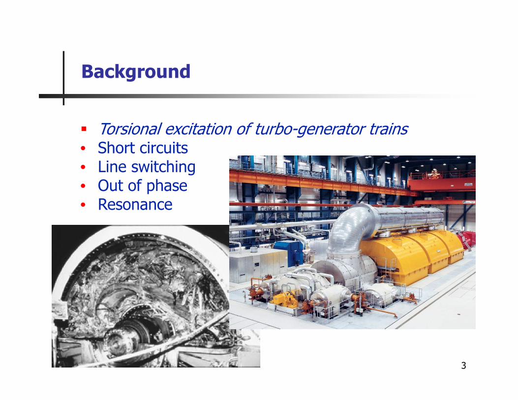
Background
3
� Torsional excitation of turbo-generator trains• Short circuits• Line switching• Out of phase• Resonance

Background
4
� Conventional modelling• 1D lumped mass/distributed parameter FE models• LP blade participation – rigid blades• Sudden diameter change• Blade-to-disk rigidity
� Improved accuracy required� Move towards full 3D, 3DCS

Research Contribution
5
� Effect of blade stagger angle• Level of blade participation• Response frequencies• Damping
� Direct comparison of different FE methodologies• Solution time• Accuracy
90° stagger angle
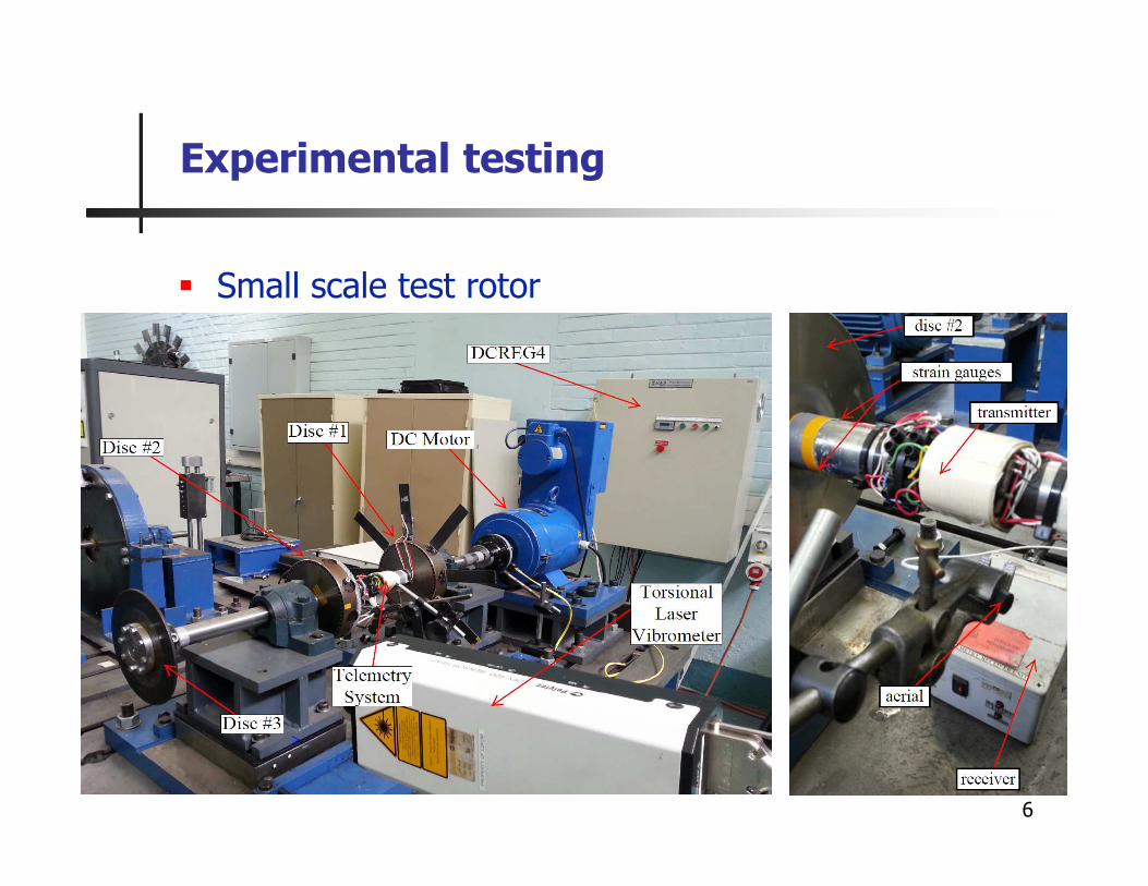
Experimental testing
6
� Small scale test rotor

Modelling Methodologies
7
� Full 3D FEA
� 3D Cyclic symmetric
� 1D lumped mass

Modelling Methodologies
8
� 1D lumped mass – blade coupling

Results
9
� Effect of blade stagger angle
90 deg 45 deg 0 deg no blades0
0.5
1
1.5
2
2.5
3
3.5
4
dam
ping
(%
)
blade stagger angle
F2
F3b
F3a
F4
0 rpm 0 rpm
90deg 45deg 0deg no blade100
150
200
250
300
350
400
450
500
550
blade stagger angle
freq
uenc
y (H
z)
F2 1D
F3b 1D
F3a 1D
F4 1D
F2 meas
F3b meas
F3a meas
F4 meas

0 500 1000 1500
150
200
250
300
350
400
450
500
550
angular velocity (rpm)
freq
uenc
y (H
z)
F2 3D
F3b 3D
F3a 3D
F4 3D
F2 meas
F3b meas
F3a meas
F4 meas
Results
10
� Effect of centrifugal force
0° blade stagger angle
0 500 1000 1500
150
200
250
300
350
400
450
500
550
angular velocity (rpm)
freq
uenc
y (H
z)
F2 3D
F3b 3D
F3a 3D
F4 3D
F2 meas
F3b meas
F3a meas
F4 meas
45° blade stagger angle

Results
11
� Effect of stagger angle on mode shapes
0 0.2 0.4 0.6 0.8 1 1.2 1.4
-0.5
0
0.5
1
normalized shaft length
norm
aliz
ed to
rsio
nal d
ispl
acem
ent
geometryF
2 0deg
F3b
0deg
F3a
0deg
F4 0deg
F2 45deg
F3b
45deg
F3a
45deg
F4 45deg
F3b
90deg
F3a
90deg
F4 90deg

Results
12
� Blade response

Results
13
� Accuracy
� Solution times• 3DCS – 80% reduction• 1D – 99% reduction
Conclusions
14
� Stagger angle affects level of blade participation� Torsional frequencies and damping is affected by stagger
angle� FE approaches are all usable depending on required
accuracy and available resources� Field testing must be done under dynamic conditions� DC motor & controller can be used for torsional excitation
of small scale test rotors

Acknowledgements
15
� Prof. PS Heyns� Dr. Abrie Oberholster� Mr. Francesco Pietra� Dr. Mark Newby � Mr. George Breitenbach� Mr. Herman Booysen� Eskom Power Plant Engineering Institute
(EPPEI)� NRF Technology and Human Resources
Programme (THRIP)