r modular framing elements structural …pic-designcatalog.com/images/pdfcat/section_9.pdfr modular...
TRANSCRIPT

DESIGN
®
www.pic-design.comInteractive catalog ■ CAD ■ e-commerce
Phone: 800-243-6125 ■ FAX: 203-758-8271E-Mail: [email protected]
PIC-STIX* modular framing elementsoffer a simplified approach to structuralconstruction that is becoming State - of - the -Art for industrial and laboratory applications.
The system consists of an asssortment ofanodized aluminum PIC-STIX extrusions incombination with a wide range of joining andfastening elements and accessories.
The PIC-STIX system allows you toconstruct structures of many configurationsand sizes. It is easy to assemble variousstructures without special training or tooling.A few simple hand tools are all that is required.
All joint connections are fastened together toprovide flexibility and quick changeover as wellas reuse of all elements.
PIC-STIX —Extrusions with T-Slot grooves are clearanodized for corrosion free finish. Thelongitudinal slots are utilized for inserting
T-Bolts and nuts anywhere along its length toattach connecting brackets and accessories.
The PIC-STIX elements consists of:■ Extrusions: Light and regular extrusions of
various constructions■ Mounting Components: Extrusion Corners,
various Brackets and Braces■ Fastening Hardware: T-Nuts, Cross and End
Connectors, Turn & Lock T-Bolts, T-Bolts,Mounting Screws and Washers
■ Accessories: Leveling and Anchoring Plates,Adjustable Legs, Casters, Handles, Hinges,End Plates, Gaskets, and Door Slide Tracks.
Typical applications for modular constructionelements:
■ Industrial & Laboratory Apparatus■ Machine Support Frames■ Linear Motion Systems■ Work Stations - Benches■ Handling & Robotic Systems■ Tooling & Fixture Supports■ Machine Guarding Structures
Ordering FlexibilityPIC Design makes it easy for you to incorpo-rate PIC-STIX in your design. Order any ofthe following options:
■ Order PIC-STIX system components sothat you can design, cut and assemble inyour shop the system you need when youneed it.
■ Design the system you want includingdetailed extrusion lengths, provide a bill ofmaterial and let PIC provide you with a kitof components ready for assembly in yourshop.
■ Provide PIC with a detailed print and bill ofmaterials, and have PIC assemble and shipthe completed system to you. This optionworks best when PIC-STIX are used as aplatform for a PIC Linear Motion System.
■ Now also available in miniature size using1/4"-20 hardware.
9-1
DESIGN
RECISIONNDUSTRIALOMPONENTS
R
R
MODULAR FRAMING ELEMENTSSTRUCTURAL EXTRUSIONS
MOUNTING HARDWARE AND ACCESSORIES
Now InStandard &Miniature
Styles

DESIGN
®
www.pic-design.comInteractive catalog ■ CAD ■ e-commerce
Phone: 800-243-6125 ■ FAX: 203-758-8271E-Mail: [email protected]
Load at center
Span
Load at center
Span Span
Load at end
7000
6500
6000
5500
5000
4500
4000
3500
3000
2500
2000
1500
1000
500
10 20 30 40 50 60 70 80 90 100 110 1205Span in inches (L)
Load
in lb
s (P)
7000
6500
6000
5500
5000
4500
4000
3500
3000
2500
2000
1500
1000
500
10 20 30 40 50 60 70 80 90 100 110 1205Span in inches (L)
Load
in lb
s (P)
2700
2500
2300
2100
1900
1700
1500
1300
1100
900
700
500
300
100
10 20 30 40 50 60 70 80 90 100 110 1205Span in inches (L)
Load
in lb
s (P)
2900
1.5 1.5
1.5 1.5
1.51.5
1.51.5
.25
.75
.75
TECHNICAL SECTIONStructural Design Guidelines — Standard
9-2
Individual profile length and load requirements should not exceed the curve in any load example. If this occurs, choosea profile with a larger section modulus to stay below the curve.
Load Condition:
Suggested Applications■■■■■ SX1010L (1" x 1") — Light
Ideal for machine guards, enclosures, anddisplays.
■■■■■ SX1015L (1" x 11/2") — LightEnclosures, benches.
■■■■■ SX1515L(11/2" x 11/2") — LightLight load bearing structures, guarding andlightweight support frames.
■■■■■ SX1515 (11/2" x 11/2") —Medium load bearing structures, a goodcombination of structural strength in acompact size.
■■■■■ SX1530 (11/2" x 3") —Used for larger and stronger structures andmachine frames. The center of this extrusioncan be used to run air or electrical lines.
■■■■■ SX3030 (3" x 3") —For larger structures where maximumstrength is desired The center of theseextrusions can also be used to run air orelectrical lines.
All PIC-STIX extrusions have a 1 or 3 degreedecline from extrusion edge to slot centerline.When fasteners are properly tightened, thefeature serves as a lock mechanism to keepthem tight.
Standard mounting and connecting bracketshave clearance holes for 5/16" dia. connect-ing screws which are all on .75" and 1.5"centers.PIC fastener brackets, extrusions, hardwareand accessories provide an unlimited systemfor structural design and assembly.
* Angle is 1O on SX1010L, SX1015L, SX1515L,and SX1545L
y =PL3
3.5 x 10⁹
y =PL3
1.89 x 10⁹
y =PL3
5.17 x 10⁸
y =PL3
2.60 x 10⁸
y =PL3
9.78 x 10⁷
y =PL3
5.28 x 10⁷
y =PL3
1.44 x 10⁷
y =PL3
7.26 x 10⁶
3O*
PIC-STIX
Profile Part Number SX3030 SX1530 SX1530 SX1515 SX1515L
Moment of Inertia-in4 3.26 .481 1.173 .242 .108
Section Modulus-in3 2.173 .641 1.76 .323 .136
y =PL3
4.65 x 10⁸
y =PL3
9.24 x 10⁸
y =PL3
3.38 x 10⁹
y =PL3
6.26 x 10⁹
y = Deflection In Inches
Fixed at both ends,load at center
Fixed at one end,load at unsupported end
Fixed at one end, sliding at one end,load at center
y = Deflection In Inches y = Deflection In Inches
DESIGN
®
www.pic-design.comInteractive catalog ■ CAD ■ e-commerce
Phone: 800-243-6125 ■ FAX: 203-758-8271E-Mail: [email protected]
10 20 30 40 50 60 70 80 90 100 110 120
Span in inches (L)
250
500
750
1000
1250
1500
1750
2000
2250
2500
2750
3000
3250
3500
Load
lbs
(P)
3750
4000
10 20 30 40 50 60 70 80 90 100 110 120
Span in inches (L)
250
500
750
1000
1250
1500
1750
2000
2250
2500
2750
3000
3250
3500
Load
lbs
(P)
10 20 30 40 50 60 70 80 90 100 110 120
Span in inches (L)
500
750
1000
1250
1500
1750
Load
lbs
(P)
250
2000
Load at center
Span
Load at center
Span Span
Load at end
9-3
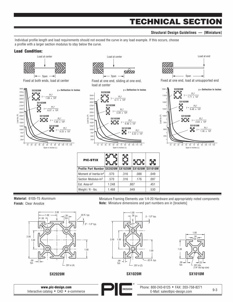
TECHNICAL SECTIONStructural Design Guidelines — [Miniature]
Individual profile length and load requirements should not exceed the curve in any load example. If this occurs, choosea profile with a larger section modulus to stay below the curve.
Load Condition:
Fixed at both ends, load at center Fixed at one end, load at unsupported endFixed at one end, sliding at one end,load at center
PIC-STIX
Profile Part Number SX2020M SX1020M SX1020M SX1010M
Moment of Inertia-in4 .570 .316 .088 .049
Section Modulus-in3 .570 .316 .176 .097
Est. Area-in2 1.248 .807 .451
Weight / ft - lbs. 1.468 .949 .530
y =PL3
9.33 x 10⁷
y =PL3
1.69 x 10⁸
y =PL3
6.07 x 10⁸
y =PL3
1.09 x 10⁹
y = Deflection In InchesSX2020M
SX1020M
SX1020M
SX1010M
y =PL3
5.22 x 10⁷
y =PL3
9.46 x 10⁷
y =PL3
3.39 x 10⁸
y =PL3
6.11 x 10⁸
y = Deflection In InchesSX2020M
SX1020M
SX1020M
SX1010M y =PL3
1.46 x 10⁶
y =PL3
2.64 x 10⁶
y =PL3
9.48 x 10⁶
y =PL3
1.71 x 10⁷
y = Deflection In InchesSX2020M
SX1020M
SX1020M
SX1010M
1.00.50
.26typ.
1.00
2.00
45°
.03 R. typ.
.09typ.
.201 ø (4)
.5° - 1.0° typ.
2.00
1.00 1.00
.26typ.
.09typ.
.23
1.00
.201 dia.(1/4" dia tap size)
1.00
2.00 1.00
1.00
.201 ø (2)
.09typ.
.02 R. typ.
.26
45°
.5 - 1.0° typ.
SX2020M SX1020M SX1010M
Material: 6105-T5 AluminumFinish: Clear Anodize
Miniature Framing Elements use 1/4-20 Hardware and appropriately noted componentsNote: Miniature dimensions and part numbers are in [brackets]

DESIGN
®
www.pic-design.comInteractive catalog ■ CAD ■ e-commerce
Phone: 800-243-6125 ■ FAX: 203-758-8271E-Mail: [email protected]
MODULAR FRAMING ELEMENTSPIC-STIX Structural T-Slot Extrusions
9-4
PIC-STIX — T-Slot Extrusions
Basic Size Wall Type Maximum Length Weight per Foot Estimated Area * Part Number*(Inch) (Inch) (lbs.) (Square Inch) (Length Code)
1.5 x 1.5 Light 144 1.03 .878 SX1515L -
1.5 x 1.5 corner Light 144 .86 .729 SX1545L -
1.5 x 1.5 Standard 144 1.40 1.164 SX1515 -
1.5 x 3.0 Standard 144 2.48 2.051 SX1530 -
3.0 x 3.0 Standard 144 3.83 3.188 SX3030 -
1.0 x 1.0 Miniature 144 .53 .451 SX1010M -
1.0 x 2.0 Miniature 144 .95 .807 SX1020M -
2.0 x 2.0 Miniature 144 1.47 1.248 SX2020M -
* Custom lengths may be ordered to .01" increments up to the maximum length.The tolerance on cuts is ±1/32". For a precision milled cut with a tolerance of±.005", add “P” after length in the part number.All custom lengths will carry an appropriate cut off charge.
NOTES: 1. Custom cut lengths on request — contact factory2. Pre-drilled access holes, connector holes, tapped endholes available on request — contact factory3. Up to 106 inch lengths shipped via UPS; over 106 inchlengths shipped via truck
Material: 6105-T5 AluminumFinish: Clear AnodizeModulus Of Elasticity: 11,000,000 PSI
������������ ��������������� �������
������ �������������� ������ ������
���
���
����
����
����
����
���� ����������� ������
�������
��������������
����
����������
����
���
���� ������� ������
�������
����
���
����
����
���
���� ����������� ������
����
���
����
���
��� ������
���
���
���� ��������� ������
�������
����
���
���
�����������
�������
����
���� ����������� ������
�������
DESIGN
®
www.pic-design.comInteractive catalog ■ CAD ■ e-commerce
Phone: 800-243-6125 ■ FAX: 203-758-8271E-Mail: [email protected]
.19
.343 DIA.[.281]
1.38[1.0]
3.00[2.0]
3.00[2.0]
3.00[2.0]
3.00[2.0]
.25[.19]
.25[.19]
.343 DIA.[.281]
2.88[2.0]
1.00
.50
.343 dia.2.00
2.00
.28 typ.
1.00 typ.
.343 DIA.[.281]
2.88[2.0]
.19
1.00
1.00
1.00.50
.343 dia.
.28 typ. 1.50[1.0]
1.38[1.0]
.343 DIA.HOLES (2)[.281]
.25[.19]
1.50[1.0]
1.50[1.0]
1.50[1.0]
.25[.19]
9-5
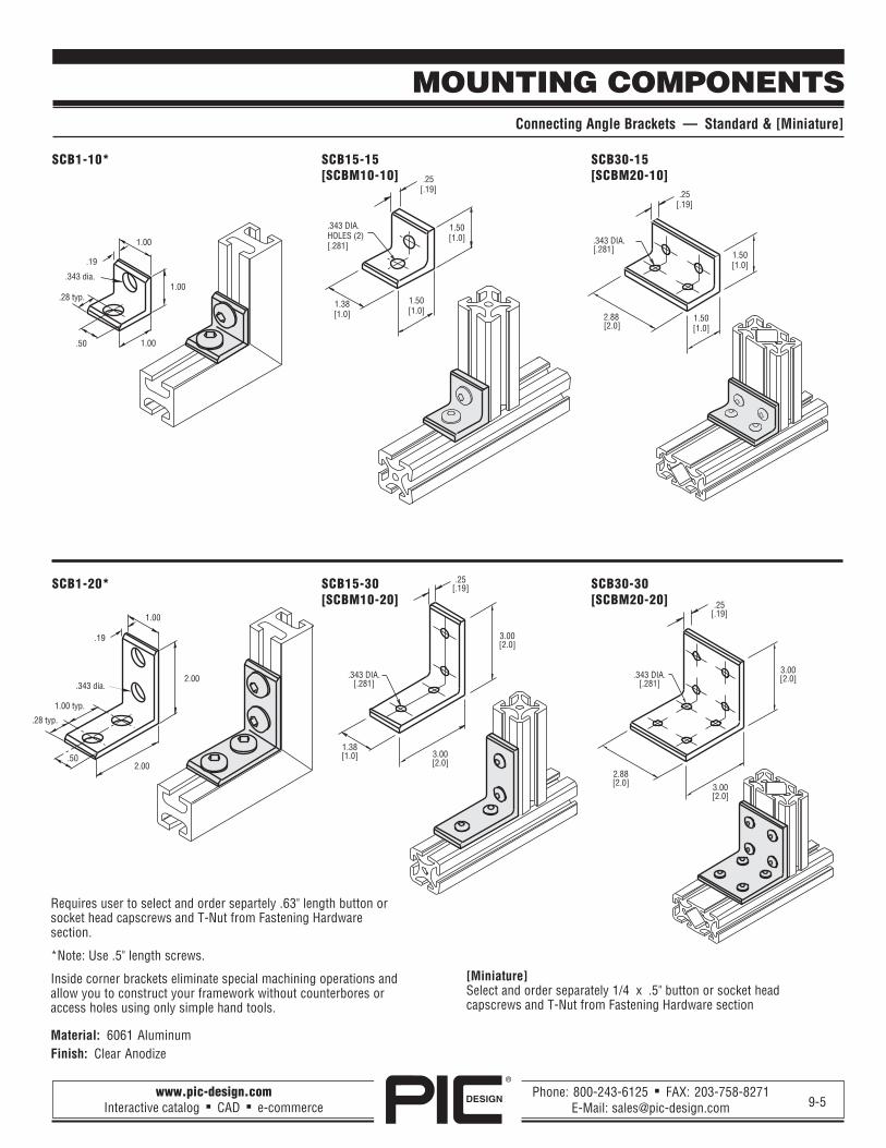
MOUNTING COMPONENTSConnecting Angle Brackets — Standard & [Miniature]
SCB1-10* SCB15-15 SCB30-15[SCBM10-10] [SCBM20-10]
SCB1-20* SCB15-30 SCB30-30[SCBM10-20] [SCBM20-20]
Requires user to select and order separtely .63" length button orsocket head capscrews and T-Nut from Fastening Hardwaresection.
*Note: Use .5" length screws.
Inside corner brackets eliminate special machining operations andallow you to construct your framework without counterbores oraccess holes using only simple hand tools.
Material: 6061 AluminumFinish: Clear Anodize
[Miniature]Select and order separately 1/4 x .5" button or socket headcapscrews and T-Nut from Fastening Hardware section

DESIGN
®
www.pic-design.comInteractive catalog ■ CAD ■ e-commerce
Phone: 800-243-6125 ■ FAX: 203-758-8271E-Mail: [email protected]
5/16-18
.50
.38
.38
Tapped for1/4-20bolts (2)
.50
.50
45°
45°
A
.343 dia.for 5/16 dia x 1.25 SHCS
5/16-18
.50
.88
.50
MOUNTING COMPONENTSExtrusion Corners / 45O Supports — Standard & [Miniature]
9-6
Extrusion corners /45° supports are designed tostrengthen corners and provide a flush andclean connection. The support connects withhardware consisting of socket head cap screws,washers and economy T-nuts (hardwareIncluded).
Material: 6061-T6 AluminumFinish: Clear Anodize
PIC-STIX A CornerExtrusion (Inches) Part NumberPart Number
SX1010L 4.00 SCX1010-4SX1515L 3.00 SCX1515-3SX1515L 9.00 SCX1515-9SX1515 3.00 SCX1515-3
SX1515 9.00 SCX1515-9SX1530 3.00 SCX1530-3SX1530 9.00 SCX1530-9SX3030 3.00 SCX3015-3SX3030 9.00 SCX3015-9SX1010M 6.00 SCX1010M-6SX1020M 6.00 SCX1020M-6
MOUNTING BRACKETSPanel Mounting Angle, Corner Joint & Straight Bracket — Standard & [Miniature]
Corner BracketsUse with extrusion part numbers SX1010Land SX1015L. Requires SCH8-05 screw andSCH2-10 nut (2ea).Material: AluminumFinish: Clear Anodize
Panel Mounting AngleRequires SCH9-06 and nut, plus appropriatepanel mounting hardware.Material: AluminumFinish: Clear Anodize
Corner Joint and Panel BracketHardware Included. Access hole suggested fortightening screw.Material: AluminumFinish: Clear Anodize
SCX1010-1 SCB1 SCB1-CP
[SCX1010M-1 requires SCH8M-05 & SCH2M-10 Nut, 2 each]
1.00
.81
1.50[1.50]
5/16 Dia. CB[1/4”]
1.50[1.50]
.343 DIA.(2) HOLES
.621.00
.50
1.00
.25 THICKPANEL
1.00
.50
.12
Panel MountHardware Included.Material: Aluminum, Finish: Clear Anodize
SCB1-P

DESIGN
®
www.pic-design.comInteractive catalog ■ CAD ■ e-commerce
Phone: 800-243-6125 ■ FAX: 203-758-8271E-Mail: [email protected]
�������� !"#�$������%
����
�������� !"#�$������% ����
���$�����%
�������� !"#� ���
���
�������� !"#�$������%
���
��$���%
���$���%
����&'(�")*+,���$����&� �%
���$��%
��$���%
����$���%
����$���%
���$���%
���$��%
����$���%
���$���%
����$���%
-. ���/01.��.23��4/.2����#��2�5��, "����$, "�6��%
���7��0,8����15,8����*$2��7��0,8����6%
����$���%
����$���%
���$���%
����&'(�")*+,���$����&� �%
���$��%��$���%
����$���%
����$���% ���$��%
����$���%
����
����&'(�")*+,��� ����
���$���%
����&'(�")*+,���$����&� �%
���$��%
��$���%
����$���%
����$���%
���$���%
���$��%
����$���%
���$���%
���$���%
����&'(�")*+,���$����&� �%
���$��%
��$���%
����$���%
����$���%
���$���%
���$��%
����$���%
�������������������� ���,233�����0 5�7 5�, "����/5�77��0!��2��������������(.29�429���� .� 5(41����
�������!�� �,233�����0 5�7 5�, "����/5�7 4�, "�42�����$, "�6����/5�7 4�, "�6���42����%��������(..1�,���.���� :. /;-17��5 1 �
�������!�� ��"���#�� ��,233�����0 5�7 5�, "����/5�7 4�, "�42�����$, "�6����/5�7 4�, "�6���42����%���������(..1�,���.���� :. /;-17��5 1 �
�������!�� �,233�����0 5�7 5�, "��� 4�, "�42�����$, "�6���/5�7 4�, "�6���42����%��������(..1�,���.���� :. /;-17��5 1 �
�������!� $��������(.29�429���� .� 5(41����
���$���%
"���#�� ����������!�� �,233�����0 5�7 5�, "����/5�7 4�, "�42�����$, "�6����/5�7 4�, "�6���42����%��������(..1�,���.���� :. /;-17��5 1 �
��!�%"&��'��!�%"(&��)
��!�%�&��'��!�%�(&��)
��!*
��!�&��'��!�(&��)
��!�%&��'��!�%(&*�)
��!�&��'��!�(&*�)
��!+'��!+()
9-7
MOUNTING COMPONENTSAdjustable Joint and Steel Corner Braces — Standard & [Miniature]
Pivot T-NutsLoads into extrusion from the side.Not to be used on SX1010L and SX1015L.
Connector T-NutsLoads into extrusion from end only.
SCH1-P SCH1[SCH1M-P]
Economy T-NutsSCH2-15 Long T-Nut[SCH2M-15]
SCH2-10 T-Nut[SCH2M-10]
Material: Alloy SteelFinish: Zinc Plate
FASTENING HARDWARE — STANDARD & [MINIATURE]
DESIGN
®
www.pic-design.comInteractive catalog ■ CAD ■ e-commerce
Phone: 800-243-6125 ■ FAX: 203-758-8271E-Mail: [email protected]
������ �<�������/=>15�
����
��������
������ �<����������
/=>15�
������ �<����������
/=>15�����
��������
����� �<�����������
01.��
����� �<�����������
����� �<�����������
�. /������
�
*
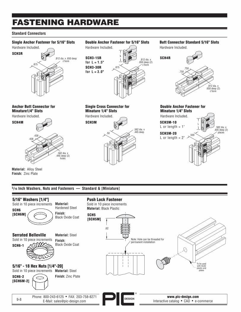
FASTENING HARDWAREStandard Connectors
9-8
5/16" Washers [1/4"]Sold in 10 piece increments
SCH6[SCH6M]
Serrated BellevilleSold in 10 piece increments
SCH6-1
5/16" - 18 Hex Nuts [1/4"-20]Sold in 10 piece increments
SCH6-2[SCH6M-2]
5/16 Inch Washers, Nuts and Fasteners — Standard & [Miniature]
Single Anchor Fastener for 5/16" SlotsHardware Included.
Double Anchor Fastener for 5/16" SlotsHardware Included.
Butt Connector Standard 5/16" SlotsHardware Included.
SCH3RSCH3-15R SCH4Rfor L = 1.5"SCH3-30Rfor L = 3.0"
Push Lock FastenerSold in 10 piece incrementsMaterial: Black Plastic
SCH5[SCH5M]
Anchor Butt Connector forMinature1/4" SlotsHardware Included.
Single Cross Connector forMinature 1/4" SlotsHardware Included.
Double Anchor Fastener forMinature 1/4" SlotsHardware Included.
SCH4M SCH3M SCH3M-10L or length = 1"
SCH3M-20L or length = 2"
Material: Alloy SteelFinish: Zinc Plate
Material: Steel
Finish: Zinc Plate
Material: Steel
Finish:Black Oxide Coat
Material:Hardened Steel
Finish:Black Oxide Coat
.62
Note: Hole can be threaded forpermanent installation
To be usedwith SCA2plastic end
plates

DESIGN
®
www.pic-design.comInteractive catalog ■ CAD ■ e-commerce
Phone: 800-243-6125 ■ FAX: 203-758-8271E-Mail: [email protected]
1/4[.19]
L
L (Inch) PartNumber
.50 SCH9-05
.63 SCH9-06
.75 SCH9-071.0 SCH9-101.25 SCH9-121.5 SCH9-15
Standard Screws
L (Inch) PartNumber
.44 SCH9M-04
.50 SCH9M-05
.63 SCH9M-06
.75 SCH9M-071.0 SCH9M-101.25 SCH9M-12
Miniature Screws
L(inch)
L(inch)
9-9
FASTENING HARDWAREFasteners / T-Slot Bolts and Screws — Standard & [Miniature]
Drop In And Turn 5/16" - 18 T-BoltsLoads into extrusion from side.Material: Alloy SteelFinish: Zinc Plate
Economy 5/16" - 18 T-BoltsLoads from end only. Sold in increments of 10 pieces.Material: Alloy SteelFinish: Zinc Plate
5/16" - 18 Standard Socket Head Cap Screws [1/4"-20]Sold in increments of 10 pieces.Material: Alloy SteelFinish: Black Oxide
5/16" - 18 Standard Button Head Cap Screws [1/4"-20]Sold in increments of 10 pieces.Material: Alloy SteelFinish: Black Oxide
L (Inch) PartNumber
.50 SCH8-05
.63 SCH8-06
.75 SCH8-071.0 SCH8-101.25 SCH8-121.5 SCH8-152.0 SCH8-20
SCH8- SCH9-
L (Inch) Part Number
.75 SCH7-071.00 SCH7-101.25 SCH7-121.50 SCH7-152.00 SCH7-20
L (Inch) Part Number
.75 SCH6-071.00 SCH6-10
SCH6- SCH7-
Plastic End PlatesUse with part number SCH5. Color: Black
SCA2-
SCA2-1515For extrusionSX1515[SCA2M-1010] for SX1010M
SCA2-1530For extrusionSX1530 [SCA2M-1020]for SX1020M
SCA2-3030For extrusionSX3030[SCA2M-2020]for SX2020M
Door Tracks, Plastic End Plates, Gasket and Covers — Standard & [Miniature]
ACCESSORIES
T-Slot Cover Panel Gasket
Standard Screws
L (Inch) PartNumber
.44 SCH8M-04
.50 SCH8M-05
.63 SCH8M-06
.75 SCH8M-071.0 SCH8M-101.25 SCH8M-12
SCH8M-Miniature Screws
L(inch)
SCH9M-
L(inch)
L
SCH5[SCH5M]
Plastic T-Slot Cover and Panel GasketSold in 6 foot lengths.
SCA3 [SCA3M] — GraySCA3Y [SCA3YM] — Yellow

DESIGN
®
www.pic-design.comInteractive catalog ■ CAD ■ e-commerce
Phone: 800-243-6125 ■ FAX: 203-758-8271E-Mail: [email protected]
.56 dia. thrufor flooranchor
[.44 Dia.]
Drilled andC'Bored
for 5/16 SHCS(2) places
[1/4-20 SHCS]
1/2-13UNC Thru
[3/8-16 UNC]
1.50 [1.00]
1.50[1.00]
2.50[1.88]
1.50[1.00]
.75 [.50]
.75[.50]
.75 [.50]
4.50[3.00]
Use withappropriateSCE Bracket
1/2-13 UNC[1/4-20]
1 1/8[.50]
3.0[1.5]
1 7/8 DIA.[1.0]
1.25[1.38]
1.50[1.0]
.62[.38]
1.75 3.00[2.50]
3.004.00
[3.75]
.38
.75
1.50[1.0]
5/16-18 UNCthru
(4) holes
Drilled andC'Bored
for 5/16 SHCS(2) places
[1/4-20 SHCS]
.75 [.50]
1.50[1.00]
Drilled andC'Bored
for 5/16 SHCS(4) places
[1/4 SHCS]
3.00[2.00]
1.50[1.00]
1/2-13UNC Thru[3/8-16
UNC Thru]
.75 [.50]
.75[.50]
1.50 [1.00]
3.00[2.00]
.75 [.50]
1.50[1.00]
Drilled andC'Bored
for 5/16 SHCS(4) places
[1/4 SHCS]
1/2-13 UNC Thru[3/8-16 UNC Thru]
.56 dia. thrufor flooranchor
1.50[1.00]
4.50[3.00]
1.50[1.00]
3.00[2.00]
.75 [.50]
.75 [.50]1.50
[1.00]
.75 [.50]
1.50[1.00]
1.75[1.13]
Drilled andC'Bored
for 5/16 SHCS(2) places
[1/4 SHCS]
3.00[2.00]
1.50[1.00]1/2-13
UNC Thru[3/8-16
UNC Thru].75 [.50]
1.50[1.00]
.75 [.50]
.75[.50]
1.50 [1.00]
ACCESSORIESLeveling, Anchor and Caster Plates. Adjustable Legs and Casters — Standard & [Miniature]
9-10
Leveling PlateRequires SCH8-10(2) [SCH8M-10].Use with SCE4 [SCE4M] adjustable leg.Material: AluminumFinish: Clear Anodize
SCE1 [SCE1M]
Leveling PlateRequires SCH8-10(4) [SCH8M-10].Use with SCE4 [SCE4] adjustable leg.Material: AluminumFinish: Clear Anodize
SCE2 [SCE2M]
Leveling Anchor PlateRequires SCH8-10(4) [SCH8M-10].Use with SCE4 [SCE4M] adjustable leg.Material: AluminumFinish: Clear Anodize
SCE2-A [SCE2M-A]
3" and 4" Caster PlateRequires SCH8-10(4).Use with SCE5 caster.Material: AluminumFinish: Clear Anodize
SCE3 [SCE3M]
Adjustable Leg1,800 pound maximum capacity.Material: SteelFinish: Bronze Coating
SCE4 [SCE4M]
Leveling Anchor PlateRequires SCH8-10(2) [SCH8M-10].Use with SCE4 [SCE4M] adjustable leg.Material: AluminumFinish: Clear Anodize
SCE1-A [SCE1M-A]
Description Part Number
3" caster-swivel SCE5-3S3" caster-fixed SCE5-3F3" caster-swivel / brake SCE5-3B4" caster-swivel SCE5-4S4" caster-fixed SCE5-4F4" caster-swivel / brake SCE5-4B
3" and 4" CasterUse with SCE3 caster plate (see above).
SCE5-
SCE5-3 SCE5-4
SCE5-3 (SCE5-3B shown)90 pound maximum capacity.
SCE5-4 (SCE5-4F shown)130 pound maximum capacity.
3" Caster 4" Caster
3 Dia.Caster
Brake
▲
.12
3.82
4 Dia.Caster
.12
5.0

DESIGN
®
www.pic-design.comInteractive catalog ■ CAD ■ e-commerce
Phone: 800-243-6125 ■ FAX: 203-758-8271E-Mail: [email protected]
1.625Dia.
[1.13]
.31[.25]
2.00Dia.
[1.38]
.375 Dia. [.31 Dia.]Boss Bronze Bearing Std.
.74[.24]
1.66
.62
1.50
3.00
3.00
1.75
.328 DIA. THRU(4) HOLES
.12
1.1[.83]
1.97[1.42]
7.047[3.68]
C’bored forSCH8-06
[SCH8M-05](2 required)
9-11
ACCESSORIESStandard & [Miniature
T-Slot RollerIdeal for guided linear applications, mount toextrusion end or T-Slot; rolls in the mating T-Slot.Hardware included.Material: Delrin with Bronze BearingColor: White
SCA6[SCA6M]
Plastic HandleColor: Black.Hardware included.
SCA9-3[SCA9M-3]
Aluminum HandleFinish: Clear Anodize.Hardware included.
SCA9-2
Magnetic Door Latch AssemblyHardware included.Material: Plastic with metal magnetColor: Brown
SCA8
Aluminium HingeFinish: Clear Anodize.
SCA7-2
Plastic HingeHardware included.Color: Black.
SCA7-1
2.50
1.88
1.50.75
2.25
.28 DIA. THRU(4) HOLES
����� �
���
����
����� �
���
����
�������
DESIGN
®
www.pic-design.comInteractive catalog ■ CAD ■ e-commerce
Phone: 800-243-6125 ■ FAX: 203-758-8271E-Mail: [email protected]
����&5�..!052!���
��� ����
���
����
���
��� ������ ��������
��&� �<���&���
����
����
����
�����
����
����
�����
�����
����
���
������
��� ����
����&� �&5�..!052
��1
����
���
������
��� �����
����&� �&5�..!052
��1
������
���
��&� �<���&���
����
����
����
�����
EndHoles
Y
XEndHoles
Y2Y1
X
EndHoles
Y2Y1
X1
X2
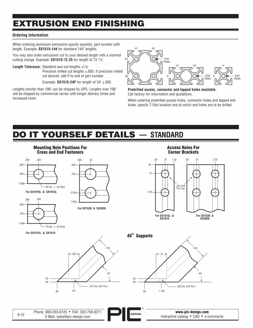
EXTRUSION END FINISHINGOrdering Information
9-12
When ordering aluminum extrusions specify quantity, part number withlength. Example: SX1515-144 for standard 144" lengths.
You may also order extrusions cut to your desired length with a nominalcutting charge. Example: SX1515-72.25 for length of 72 1/4".
Length Tolerance: Standard saw cut lengths ±1/32
Precision milled cut lengths ±.005. If precision milledcut desired, add P to end of part number
Example: SX1515-24P for length of 24" ±.005
Lengths shorter than 106" can be shipped by UPS. Lengths over 106"will be shipped by commercial carrier with longer delivery times andincreased costs.
DO IT YOURSELF DETAILS — STANDARD
Mounting Hole Positions ForCross and End Fasteners
Access Holes ForCorner Brackets
Predrilled access, connector and tapped holes available.Call factory for information and quotations.
When ordering predrilled access holes, connector holes and tapped endholes, specify T-Slot location and at which end holes are to be drilled.
45o Supports
For SX1010L & SX1015L
For SX1515L & SX1515
For SX1530 & SX3030
For SX1515L &SX1515
For SX1530 &SX3030