r-j3ib mate maintenance manual for europe b-81525en-1-01
TRANSCRIPT

FANUC Robot series
MAINTENANCE MANUAL
B--81525EN--1/01
For Europe
R--J3iB Mate CONTROLLER
B--81525EN--1/01 Table of Contents
c--1
PREFACE p--1. . . . . . . . . . . . . . . . . . . . . . . . . . . . . . . . . . . . . . . . . . . . . . . . . . . . . . . . . . . . . . . .
I SAFETY PRECAUTIONS
1. SAFETY PRECAUTIONS 3. . . . . . . . . . . . . . . . . . . . . . . . . . . . . . . . . . . . . . . . . . . . . . .1.1 OPERATOR SAFETY 4. . . . . . . . . . . . . . . . . . . . . . . . . . . . . . . . . . . . . . . . . . . . . . . . . . . . . . . . . . . .
1.1.1 Operator Safety 6. . . . . . . . . . . . . . . . . . . . . . . . . . . . . . . . . . . . . . . . . . . . . . . . . . . . . . . . . . . . . . . . . . .1.1.2 Safety of the Teach Pendant Operator 7. . . . . . . . . . . . . . . . . . . . . . . . . . . . . . . . . . . . . . . . . . . . . . . . . .1.1.3 Safety During Maintenance 9. . . . . . . . . . . . . . . . . . . . . . . . . . . . . . . . . . . . . . . . . . . . . . . . . . . . . . . . .
1.2 SAFETY OF THE TOOLS AND PERIPHERAL DEVICES 10. . . . . . . . . . . . . . . . . . . . . . . . . . . . . .1.2.1 Precautions in Programming 10. . . . . . . . . . . . . . . . . . . . . . . . . . . . . . . . . . . . . . . . . . . . . . . . . . . . . . . . .1.2.2 Precautions for Mechanism 10. . . . . . . . . . . . . . . . . . . . . . . . . . . . . . . . . . . . . . . . . . . . . . . . . . . . . . . . . .
1.3 SAFETY OF THE ROBOT MECHANISM 11. . . . . . . . . . . . . . . . . . . . . . . . . . . . . . . . . . . . . . . . . . . .1.3.1 Precautions in Operation 11. . . . . . . . . . . . . . . . . . . . . . . . . . . . . . . . . . . . . . . . . . . . . . . . . . . . . . . . . . . .1.3.2 Precautions in Programming 11. . . . . . . . . . . . . . . . . . . . . . . . . . . . . . . . . . . . . . . . . . . . . . . . . . . . . . . . .1.3.3 Precautions for Mechanisms 11. . . . . . . . . . . . . . . . . . . . . . . . . . . . . . . . . . . . . . . . . . . . . . . . . . . . . . . . .
1.4 SAFETY OF THE END EFFECTOR 12. . . . . . . . . . . . . . . . . . . . . . . . . . . . . . . . . . . . . . . . . . . . . . . . .1.4.1 Precautions in Programming 12. . . . . . . . . . . . . . . . . . . . . . . . . . . . . . . . . . . . . . . . . . . . . . . . . . . . . . . . .
1.5 SAFETY IN MAINTENANCE 13. . . . . . . . . . . . . . . . . . . . . . . . . . . . . . . . . . . . . . . . . . . . . . . . . . . . .
1.6 WARNING LABEL 14. . . . . . . . . . . . . . . . . . . . . . . . . . . . . . . . . . . . . . . . . . . . . . . . . . . . . . . . . . . . . .
II MAINTENANCE
1. OVERVIEW 19. . . . . . . . . . . . . . . . . . . . . . . . . . . . . . . . . . . . . . . . . . . . . . . . . . . . . . . . . . .
2. CONFIGURATION 20. . . . . . . . . . . . . . . . . . . . . . . . . . . . . . . . . . . . . . . . . . . . . . . . . . . . .2.1 EXTERNAL VIEW OF THE CONTROLLER 21. . . . . . . . . . . . . . . . . . . . . . . . . . . . . . . . . . . . . . . . .
2.2 COMPONENT FUNCTIONS 24. . . . . . . . . . . . . . . . . . . . . . . . . . . . . . . . . . . . . . . . . . . . . . . . . . . . . . .
2.3 PREVENTIVE MAINTENANCE 25. . . . . . . . . . . . . . . . . . . . . . . . . . . . . . . . . . . . . . . . . . . . . . . . . . .
3. TROUBLESHOOTING 26. . . . . . . . . . . . . . . . . . . . . . . . . . . . . . . . . . . . . . . . . . . . . . . . . .3.1 POWER CANNOT BE TURNED ON 27. . . . . . . . . . . . . . . . . . . . . . . . . . . . . . . . . . . . . . . . . . . . . . . .
3.1.1 Teach Pendant Cannot be Turned On 28. . . . . . . . . . . . . . . . . . . . . . . . . . . . . . . . . . . . . . . . . . . . . . . . . .3.1.2 Initial Screen Remains on the Teach Pendant 29. . . . . . . . . . . . . . . . . . . . . . . . . . . . . . . . . . . . . . . . . . . .
3.2 ALARM OCCURRENCE SCREEN 30. . . . . . . . . . . . . . . . . . . . . . . . . . . . . . . . . . . . . . . . . . . . . . . . .
3.3 SAFETY SIGNALS 33. . . . . . . . . . . . . . . . . . . . . . . . . . . . . . . . . . . . . . . . . . . . . . . . . . . . . . . . . . . . . .
3.4 MASTERING 34. . . . . . . . . . . . . . . . . . . . . . . . . . . . . . . . . . . . . . . . . . . . . . . . . . . . . . . . . . . . . . . . . . .
3.5 TROUBLESHOOTING USING THE ERROR CODE 36. . . . . . . . . . . . . . . . . . . . . . . . . . . . . . . . . . .
3.6 TROUBLESHOOTING USING FUSES 92. . . . . . . . . . . . . . . . . . . . . . . . . . . . . . . . . . . . . . . . . . . . . .
3.7 TROUBLESHOOTING BASED ON LED INDICATIONS 96. . . . . . . . . . . . . . . . . . . . . . . . . . . . . . .
3.8 POSITION DEVIATION FOUND IN RETURN TO THE REFERENCE POSITION(POSITIONING) 106. . . . . . . . . . . . . . . . . . . . . . . . . . . . . . . . . . . . . . . . . . . . . . . . . . . . . . . . . . . . . . . . .
3.9 VIBRATION OBSERVED DURING MOVEMENT 107. . . . . . . . . . . . . . . . . . . . . . . . . . . . . . . . . . . . .
3.10 MANUAL OPERATION IMPOSSIBLE 108. . . . . . . . . . . . . . . . . . . . . . . . . . . . . . . . . . . . . . . . . . . . . .

B--81525EN--1/01Table of Contents
c--2
4. PRINTED CIRCUIT BOARDS 110. . . . . . . . . . . . . . . . . . . . . . . . . . . . . . . . . . . . . . . . . . . .4.1 ROBOT CONTROLLER PC BOARD (A16B--3200--0450) 111. . . . . . . . . . . . . . . . . . . . . . . . . . . . . . .
4.2 EMERGENCY STOP PC BOARD (A20B--1008--0022, --0023) 115. . . . . . . . . . . . . . . . . . . . . . . . . . . .
4.3 BACKPLANE PC BOARD (A20B--2003--0330) 116. . . . . . . . . . . . . . . . . . . . . . . . . . . . . . . . . . . . . . . .
5. SERVO AMPLIFIERS 117. . . . . . . . . . . . . . . . . . . . . . . . . . . . . . . . . . . . . . . . . . . . . . . . . . .5.1 OUTLINE DRAWINGS 118. . . . . . . . . . . . . . . . . . . . . . . . . . . . . . . . . . . . . . . . . . . . . . . . . . . . . . . . . . .
5.1.1 Power Supply Module PSM (A06B--6115--H001) 118. . . . . . . . . . . . . . . . . . . . . . . . . . . . . . . . . . . . . . . .5.1.2 Servo Amplifier Module (A06B--6114--H205, A06B--6114--H302) 119. . . . . . . . . . . . . . . . . . . . . . . . . . .
5.2 LED OF SERVO AMPLIFIER 120. . . . . . . . . . . . . . . . . . . . . . . . . . . . . . . . . . . . . . . . . . . . . . . . . . . . . .5.2.1 LED of Power Supply Module 120. . . . . . . . . . . . . . . . . . . . . . . . . . . . . . . . . . . . . . . . . . . . . . . . . . . . . . .5.2.2 LED of Servo Amplifier Module 121. . . . . . . . . . . . . . . . . . . . . . . . . . . . . . . . . . . . . . . . . . . . . . . . . . . . .
6. SETTING THE POWER SUPPLY 122. . . . . . . . . . . . . . . . . . . . . . . . . . . . . . . . . . . . . . . . .6.1 BLOCK DIAGRAMS OF THE POWER SUPPLY 123. . . . . . . . . . . . . . . . . . . . . . . . . . . . . . . . . . . . . .
6.2 CHECKING THE POWER SUPPLY UNIT 124. . . . . . . . . . . . . . . . . . . . . . . . . . . . . . . . . . . . . . . . . . .
6.3 CHECKING THE POWER SUPPLY MODULE 124. . . . . . . . . . . . . . . . . . . . . . . . . . . . . . . . . . . . . . . .
6.4 SELECTING THE TRANSFORMER CONNECTION 125. . . . . . . . . . . . . . . . . . . . . . . . . . . . . . . . . . .
7. REPLACING A UNIT 126. . . . . . . . . . . . . . . . . . . . . . . . . . . . . . . . . . . . . . . . . . . . . . . . . . .7.1 REPLACING THE PRINTED--CIRCUIT BOARDS 127. . . . . . . . . . . . . . . . . . . . . . . . . . . . . . . . . . . .
7.1.1 Replacing the Backplane Board (Unit) 128. . . . . . . . . . . . . . . . . . . . . . . . . . . . . . . . . . . . . . . . . . . . . . . . .7.1.2 Replacing the Robot Controller PC Board and Printed--Circuit Boards on the Backplane Unit 129. . . . . .7.1.3 Replacing the Emergency Stop PC Board 130. . . . . . . . . . . . . . . . . . . . . . . . . . . . . . . . . . . . . . . . . . . . . . .
7.2 REPLACING CARDS AND MODULES ON THE ROBOT CONTROLLER PC BOARD 131. . . . . .
7.3 REPLACING THE TRANSFORMER 135. . . . . . . . . . . . . . . . . . . . . . . . . . . . . . . . . . . . . . . . . . . . . . . .7.3.1 Replacing the Brake Power Transformer 135. . . . . . . . . . . . . . . . . . . . . . . . . . . . . . . . . . . . . . . . . . . . . . .7.3.2 Replacing the Power Transformer 136. . . . . . . . . . . . . . . . . . . . . . . . . . . . . . . . . . . . . . . . . . . . . . . . . . . . .
7.4 REPLACING THE EMERGENCY STOP UNIT 137. . . . . . . . . . . . . . . . . . . . . . . . . . . . . . . . . . . . . . .
7.5 REPLACING THE MAGNETIC CONTACTOR 138. . . . . . . . . . . . . . . . . . . . . . . . . . . . . . . . . . . . . . .
7.6 REPLACING SERVO AMPLIFIERS 139. . . . . . . . . . . . . . . . . . . . . . . . . . . . . . . . . . . . . . . . . . . . . . . .
7.7 REPLACING THE TEACH PENDANT 140. . . . . . . . . . . . . . . . . . . . . . . . . . . . . . . . . . . . . . . . . . . . . .
7.8 REPLACING THE CONTROL SECTION FAN MOTOR 141. . . . . . . . . . . . . . . . . . . . . . . . . . . . . . . .
7.9 REPLACING THE FAN MOTOR OF THE SERVO AMPLIFIER CONTROL UNIT 142. . . . . . . . . .
7.10 REPLACING THE DOOR FAN UNIT AND HEAT EXCHANGER 143. . . . . . . . . . . . . . . . . . . . . . . .
7.11 REPLACING THE OPERATOR PANEL 144. . . . . . . . . . . . . . . . . . . . . . . . . . . . . . . . . . . . . . . . . . . . .
7.12 REPLACING THE POWER SUPPLY UNIT 145. . . . . . . . . . . . . . . . . . . . . . . . . . . . . . . . . . . . . . . . . .
7.13 REPLACING A FUSE 146. . . . . . . . . . . . . . . . . . . . . . . . . . . . . . . . . . . . . . . . . . . . . . . . . . . . . . . . . . . .7.13.1 Replacing a Fuse on the Robot Controller PC Board 146. . . . . . . . . . . . . . . . . . . . . . . . . . . . . . . . . . . . . .7.13.2 Replacing a Fuse on the Emergency Stop PC Board 147. . . . . . . . . . . . . . . . . . . . . . . . . . . . . . . . . . . . . . .7.13.3 Replacing the Fuse on the Power Supply Module 148. . . . . . . . . . . . . . . . . . . . . . . . . . . . . . . . . . . . . . . . .7.13.4 Replacing the Fuse on the Servo Amplifier Module 149. . . . . . . . . . . . . . . . . . . . . . . . . . . . . . . . . . . . . . .
7.14 REPLACING A RELAY 150. . . . . . . . . . . . . . . . . . . . . . . . . . . . . . . . . . . . . . . . . . . . . . . . . . . . . . . . . .7.14.1 Replacing a Relay on the Emergency Stop PC Board 150. . . . . . . . . . . . . . . . . . . . . . . . . . . . . . . . . . . . . .
7.15 REPLACING BATTERY 151. . . . . . . . . . . . . . . . . . . . . . . . . . . . . . . . . . . . . . . . . . . . . . . . . . . . . . . . . .7.15.1 Battery for Memory Backup (3 VDC) 151. . . . . . . . . . . . . . . . . . . . . . . . . . . . . . . . . . . . . . . . . . . . . . . . .

B--81525EN--1/01 Table of Contents
c--3
III CONNECTION
1. GENERAL 155. . . . . . . . . . . . . . . . . . . . . . . . . . . . . . . . . . . . . . . . . . . . . . . . . . . . . . . . . . . .
2. BLOCK DIAGRAM 156. . . . . . . . . . . . . . . . . . . . . . . . . . . . . . . . . . . . . . . . . . . . . . . . . . . . .
3. CONNECTION DETAILS 157. . . . . . . . . . . . . . . . . . . . . . . . . . . . . . . . . . . . . . . . . . . . . . . .3.1 CONNECTING THE POWER SUPPLY CABLE 158. . . . . . . . . . . . . . . . . . . . . . . . . . . . . . . . . . . . . . .
3.2 FANUC I/O LINK 159. . . . . . . . . . . . . . . . . . . . . . . . . . . . . . . . . . . . . . . . . . . . . . . . . . . . . . . . . . . . . . . .
3.3 CONNECTING THE I/O LINK CABLE 161. . . . . . . . . . . . . . . . . . . . . . . . . . . . . . . . . . . . . . . . . . . . . .
3.4 EMERGENCY STOP CIRCUIT 163. . . . . . . . . . . . . . . . . . . . . . . . . . . . . . . . . . . . . . . . . . . . . . . . . . . .3.4.1 Emergency Stop Circuit Diagram 163. . . . . . . . . . . . . . . . . . . . . . . . . . . . . . . . . . . . . . . . . . . . . . . . . . . . .3.4.2 External Emergency Stop Input 164. . . . . . . . . . . . . . . . . . . . . . . . . . . . . . . . . . . . . . . . . . . . . . . . . . . . . .3.4.3 External Emergency Stop Output 165. . . . . . . . . . . . . . . . . . . . . . . . . . . . . . . . . . . . . . . . . . . . . . . . . . . . .
3.5 CONNECTION OF SERVO AMPLIFIER 166. . . . . . . . . . . . . . . . . . . . . . . . . . . . . . . . . . . . . . . . . . . . .
3.6 CONNECTION OF ROBOT 167. . . . . . . . . . . . . . . . . . . . . . . . . . . . . . . . . . . . . . . . . . . . . . . . . . . . . . .
3.7 CONNECTION OF TEACH PENDANT CABLE 168. . . . . . . . . . . . . . . . . . . . . . . . . . . . . . . . . . . . . . .
3.8 CONNECTION OF CABLE FOR RS--232--C/RS--422 169. . . . . . . . . . . . . . . . . . . . . . . . . . . . . . . . . . .
3.9 CONNECTING A CABLE TO A PERIPHERAL DEVICE 170. . . . . . . . . . . . . . . . . . . . . . . . . . . . . . .3.9.1 Peripheral Device Interfaces CRM79 and CRM81 170. . . . . . . . . . . . . . . . . . . . . . . . . . . . . . . . . . . . . . . .3.9.2 When the Robot is Connected to the CNC by a Peripheral Device Cable 171. . . . . . . . . . . . . . . . . . . . . . .3.9.3 Digital I/O Signal Specifications 182. . . . . . . . . . . . . . . . . . . . . . . . . . . . . . . . . . . . . . . . . . . . . . . . . . . . . .
3.9.3.1 Peripheral device interface CRM 79 and CRM 81 182. . . . . . . . . . . . . . . . . . . . . . . . . . . . . . . . . .
3.9.4 Peripheral Device Cable Connector 184. . . . . . . . . . . . . . . . . . . . . . . . . . . . . . . . . . . . . . . . . . . . . . . . . . .3.9.5 Recommended Cables 185. . . . . . . . . . . . . . . . . . . . . . . . . . . . . . . . . . . . . . . . . . . . . . . . . . . . . . . . . . . . .
3.10 END EFFECTOR INTERFACE 186. . . . . . . . . . . . . . . . . . . . . . . . . . . . . . . . . . . . . . . . . . . . . . . . . . . . .3.10.1 Connecting the Mechanical Unit and End Effector 186. . . . . . . . . . . . . . . . . . . . . . . . . . . . . . . . . . . . . . . .3.10.2 Digital I/O Signal Specifications of End Effecter Control Interface 188. . . . . . . . . . . . . . . . . . . . . . . . . . .
3.11 TREATMENT FOR THE SHIELDED CABLE 189. . . . . . . . . . . . . . . . . . . . . . . . . . . . . . . . . . . . . . . . .
4. TRANSPORTATION AND INSTALLATION 190. . . . . . . . . . . . . . . . . . . . . . . . . . . . . . . .4.1 TRANSPORTATION 191. . . . . . . . . . . . . . . . . . . . . . . . . . . . . . . . . . . . . . . . . . . . . . . . . . . . . . . . . . . . .
4.2 INSTALLATION 191. . . . . . . . . . . . . . . . . . . . . . . . . . . . . . . . . . . . . . . . . . . . . . . . . . . . . . . . . . . . . . . .
4.3 EXTERNAL CONTROLLER DIMENSIONS 192. . . . . . . . . . . . . . . . . . . . . . . . . . . . . . . . . . . . . . . . . .
4.4 INSTALLATION CONDITION 193. . . . . . . . . . . . . . . . . . . . . . . . . . . . . . . . . . . . . . . . . . . . . . . . . . . . .
4.5 ADJUSTMENT AND CHECKS AT INSTALLATION 193. . . . . . . . . . . . . . . . . . . . . . . . . . . . . . . . . . .
4.6 NOTE AT INSTALLATION 194. . . . . . . . . . . . . . . . . . . . . . . . . . . . . . . . . . . . . . . . . . . . . . . . . . . . . . . .
4.7 DISABLING HAND BREAK 194. . . . . . . . . . . . . . . . . . . . . . . . . . . . . . . . . . . . . . . . . . . . . . . . . . . . . .
APPENDIX
A. TOTAL CONNECTION DIAGRAM 197. . . . . . . . . . . . . . . . . . . . . . . . . . . . . . . . . . . . . . . .
B. PERIPHERAL INTERFACE 208. . . . . . . . . . . . . . . . . . . . . . . . . . . . . . . . . . . . . . . . . . . . .B.1 SIGNAL TYPES 209. . . . . . . . . . . . . . . . . . . . . . . . . . . . . . . . . . . . . . . . . . . . . . . . . . . . . . . . . . . . . . . . .

B--81525EN--1/01Table of Contents
c--4
B.2 I/O SIGNALS 210. . . . . . . . . . . . . . . . . . . . . . . . . . . . . . . . . . . . . . . . . . . . . . . . . . . . . . . . . . . . . . . . . . .B.2.1 Input Signals 210. . . . . . . . . . . . . . . . . . . . . . . . . . . . . . . . . . . . . . . . . . . . . . . . . . . . . . . . . . . . . . . . . . . . .B.2.2 Output signals 211. . . . . . . . . . . . . . . . . . . . . . . . . . . . . . . . . . . . . . . . . . . . . . . . . . . . . . . . . . . . . . . . . . . .
B.3 SPECIFICATIONS OF DIGITAL INPUT/OUTPUT 212. . . . . . . . . . . . . . . . . . . . . . . . . . . . . . . . . . . . .B.3.1 Overview 212. . . . . . . . . . . . . . . . . . . . . . . . . . . . . . . . . . . . . . . . . . . . . . . . . . . . . . . . . . . . . . . . . . . . . . .B.3.2 Input/Output Hardware Usable in the R-J3iB Mate Controller 212. . . . . . . . . . . . . . . . . . . . . . . . . . . . . . .B.3.3 Software Specifications 213. . . . . . . . . . . . . . . . . . . . . . . . . . . . . . . . . . . . . . . . . . . . . . . . . . . . . . . . . . . .
C. OPTICAL FIBER CABLE 214. . . . . . . . . . . . . . . . . . . . . . . . . . . . . . . . . . . . . . . . . . . . . . .

B--81525EN--1/01 PREFACE
p--1
PREFACE
This manual describes the following models.
Model Abbreviation
FANUC Robot LR Mate 100iB LR Mate100iB
FANUC Robot LR Mate 200iB LR Mate200iB

I SAFETY PRECAUTIONS

B--81525EN--1/01 1. SAFETY PRECAUTIONSSAFETY PRECAUTIONS
3
1 SAFETY PRECAUTIONS
For the safety of the operator and the system, follow all safety precautionswhen operating a robot and its peripheral devices installed in a work cell.

1. SAFETY PRECAUTIONS B--81525EN--1/01SAFETY PRECAUTIONS
4
Operator safety is the primary safety consideration. Because it is verydangerous to enter the operating space of the robot during automaticoperation, adequate safety precautions must be observed.
The following lists the general safety precautions. Careful considerationmust be made to ensure operator safety.
(1) Have the robot system operators attend the training courses held byFANUC.
FANUC provides various training courses. Contact our sales office for details.
(2) Even when the robot is stationary, it is possible that the robot is stillready to move state and is waiting for a signal. In this state, the robotis regarded as still in motion. To ensure operator safety, provide thesystem with an alarm to indicate visually or aurally that the robot isin motion.
(3) Install a safety fence with a gate so that no operator can enter the workarea without passing through the gate. Equip the gate with aninterlock that stops the robot when the gate is opened.
The controller is designed to receive this interlock signal. When the gate isopened and this signal received, the controller stops the robot in an emergency.For connection, see Fig.1.1.
(4) Provide the peripheral devices with appropriate grounding (Class 1,Class 2, or Class 3).
(5) Try to install the peripheral devices outside the work area.
(6) Draw an outline on the floor, clearly indicating the range of the robotmotion, including the tools such as a hand.
(7) Install a mat switch or photoelectric switch on the floor with aninterlock to a visual or aural alarm that stops the robot when anoperator enters the work area.
(8) If necessary, install a safety lock so that no one except the operatorin charge can turn on the power of the robot.
The circuit breaker installed in the controller is designed to disable anyone fromturning it on when it is locked with a padlock.
1.1OPERATOR SAFETY

B--81525EN--1/01 1. SAFETY PRECAUTIONSSAFETY PRECAUTIONS
5
(9) When adjusting each peripheral device independently, be sure to turnoff the power of the robot.
Safety gate which executes with opening the door.
Fig.1.1 Safety Fence and Safety Gate

1. SAFETY PRECAUTIONS B--81525EN--1/01SAFETY PRECAUTIONS
6
The operator is a person who operates the robot system. In this sense, aworker who operates the teach pendant is also an operator. However, thissection does not apply to teach pendant operators.
(1) If it is not necessary for the robot to operate, turn off the power of therobot controller or press the EMERGENCY STOP button, and thenproceed with necessary work.
(2) Operate the robot system at a location outside the work area.
(3) Install a safety fence with a safety gate to prevent any worker otherthan the operator from entering the work area unexpectedly and alsoto prevent the worker from entering a dangerous area.
(4) Install an EMERGENCY STOP button within the operator’s reach.
The robot controller is designed to be connected to an external EMERGENCYSTOP button. With this connection, the controller stops the robot operationwhen the external EMERGENCY STOP button is pressed. See the diagrambelow for connection.
EMGIN1
Emergency stop P.C. board
Note) Connect to EMGIN1 and EMGIN2 are on the emergency stop P.C. board
External EMERGENCY STOP button
EMGIN2
Fig.1.1.1 Connection Diagram for External Emergency Stop Switch
1.1.1Operator Safety

B--81525EN--1/01 1. SAFETY PRECAUTIONSSAFETY PRECAUTIONS
7
While teaching the robot, it is necessary for the operator to enter the workarea of the robot. It is particularly necessary to ensure the safety of theteach pendant operator.
(1) Unless it is specifically necessary to enter the robot work area, carryout all tasks outside the area.
(2) Before teaching the robot, check that the robot and its peripheraldevices are all in the normal operating condition.
(3) When entering the robot work area and teaching the robot, be sure tocheck the location and condition of the safety devices (such as theEMERGENCY STOP button and the deadman switch on the teachpendant).
FANUC’s teach pendant has a switch for enabling or disabling the robot opera-tion from the teach pendant and a deadman switch in addition to the EMER-GENCY STOP button. The switches function as follows.
EMERGENCY STOP button : Pressing this button always brings the robotto an emergency stop, irrespective of thestate of the enable/disable switch.
Deadman switch : The function of this switch depends on thestate of the enable/disable switch.
In the enable position -- Releasing the deadman switch brings therobot to an emergency stop.
In the disable position -- The deadman switch is disabled.
Note)The deadman switch is provided to bring the robot to an emergencystop when the operator releases the teach pendant in an emergency.
(4) The teach pendant operator should pay careful attention so that noother workers enter the robot work area.
NOTEIn addition to the above, the teach pendant enable switch and thedeadman switch also have the following function.
By pressing the deadman switch while the enable switch is on, theemergency stop factor (normally the safety gate) connected toFENCE1 and FENCE2 of the controller is invalidated. In this case,it is possible for an operator to enter the fence during teachoperation without making the robot in the emergency stopcondition. In other words, the system understands that thecombined operations of pressing the teach pendant enable switchand pressing the deadman switch indicates the start of teaching.The teach pendant operator should be well aware that the safety gateis not functional under this condition and bear full responsibility toensure that no one enters the fence during teaching.
(5) When entering the robot work area, the teach pendant operator shouldenable the teach pendant whenever he or she enters the robot workarea. In particular, while the teach pendant enable switch is off, makecertain that no start command is sent to the robot from any operatorpanel other than the teach pendant.
The teach pendant, operator panel, and peripheral device interface send eachrobot start signal. However the validity of each signal changes as follows de-pending on the mode of the teach pendant enable switch, the three modeswitch and the remote switch on the operator’s panel.
1.1.2Safety of the TeachPendant Operator
1. SAFETY PRECAUTIONS B--81525EN--1/01SAFETY PRECAUTIONS
8
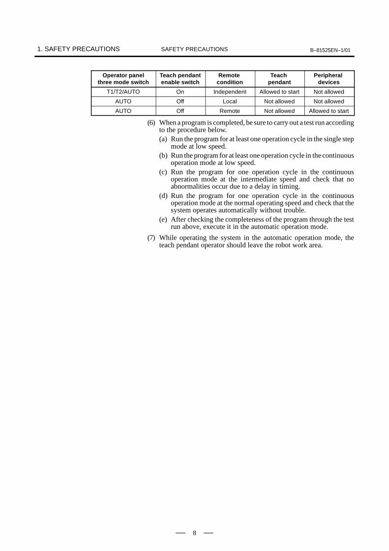
Operator panelthree mode switch
Teach pendantenable switch
Remotecondition
Teachpendant
Peripheraldevices
T1/T2/AUTO On Independent Allowed to start Not allowed
AUTO Off Local Not allowed Not allowed
AUTO Off Remote Not allowed Allowed to start
(6) When a program is completed, be sure to carry out a test run accordingto the procedure below.(a) Run the program for at least one operation cycle in the single step
mode at low speed.(b) Run the program for at least one operation cycle in the continuous
operation mode at low speed.(c) Run the program for one operation cycle in the continuous
operation mode at the intermediate speed and check that noabnormalities occur due to a delay in timing.
(d) Run the program for one operation cycle in the continuousoperation mode at the normal operating speed and check that thesystem operates automatically without trouble.
(e) After checking the completeness of the program through the testrun above, execute it in the automatic operation mode.
(7) While operating the system in the automatic operation mode, theteach pendant operator should leave the robot work area.

B--81525EN--1/01 1. SAFETY PRECAUTIONSSAFETY PRECAUTIONS
9
For the safety of maintenance personnel, pay utmost attention to thefollowing.
(1) Except when specifically necessary, turn off the power of thecontroller while carrying out maintenance. Lock the power switch,if necessary, so that no other person can turn it on.
(2) When disconnecting the pneumatic system, be sure to reduce thesupply pressure.
(3) Before the start of teaching, check that the robot and its peripheraldevices are all in the normal operating condition.
(4) If it is necessary to enter the robot work area for maintenance whenthe power is turned on, the worker should indicate that the machineis being serviced and make certain that no one starts the robotunexpectedly.
(5) Do not operate the robot in the automatic mode while anybody is inthe robot work area.
(6) When it is necessary to maintain the robot alongside a wall orinstrument, or when multiple workers are working nearby, makecertain that their escape path is not obstructed.
(7) When a tool is mounted on the robot, or when any moving deviceother than the robot is installed, such as belt conveyor, pay carefulattention to its motion.
(8) If necessary, have a worker who is familiar with the robot systemstand beside the operator panel and observe the work beingperformed. If any danger arises, the worker should be ready to pressthe EMERGENCY STOP button at any time.
(9) When replacing or reinstalling components, take care to preventforeign matter from entering the system.
(10)When handling each unit or printed circuit board in the controllerduring inspection, turn off the power of the controller and also turnoff the circuit breaker to protect against electric shock.
(11) When replacing parts, be sure to use those specified by FANUC.In particular, never use fuses or other parts of non-specified ratings.They may cause a fire or result in damage to the components in thecontroller.
1.1.3Safety DuringMaintenance

1. SAFETY PRECAUTIONS B--81525EN--1/01SAFETY PRECAUTIONS
10
(1) Use a limit switch or other sensor to detect a dangerous condition and,if necessary, design the program to stop the robot when the sensorsignal is received.
(2) Design the program to stop the robot when an abnormal conditionoccurs in any other robots or peripheral devices, even though therobot itself is normal.
(3) For a system in which the robot and its peripheral devices are insynchronous motion, particular care must be taken in programmingso that they do not interfere with each other.
(4) Provide a suitable interface between the robot and its peripheraldevices so that the robot can detect the states of all devices in thesystem and can be stopped according to the states.
(1) Keep the component cells of the robot system clean, and operate therobot in an environment free of grease, water, and dust.
(2) Employ a limit switch or mechanical stopper to limit the robot motionso that the robot does not come into contact with its peripheral devicesor tools.
1.2SAFETY OF THETOOLS ANDPERIPHERALDEVICES
1.2.1Precautions inProgramming
1.2.2Precautions forMechanism

B--81525EN--1/01 1. SAFETY PRECAUTIONSSAFETY PRECAUTIONS
11
(1) When operating the robot in the jog mode, set it at an appropriatespeed so that the operator can manage the robot in any eventuality.
(2) Before pressing the jog key, be sure you know in advance whatmotion the robot will perform in the jog mode.
(1) When the work areas of robots overlap, make certain that the motionsof the robots do not interfere with each other.
(2) Be sure to specify the predetermined work origin in a motion programfor the robot and program the motion so that it starts from the originand terminates at the origin.Make it possible for the operator to easily distinguish at a glance thatthe robot motion has terminated.
(1) Keep the work area of the robot clean, and operate the robot in anenvironment free of grease, water, and dust.
1.3SAFETY OF THEROBOT MECHANISM
1.3.1Precautions inOperation
1.3.2Precautions inProgramming
1.3.3Precautions forMechanisms

1. SAFETY PRECAUTIONS B--81525EN--1/01SAFETY PRECAUTIONS
12
(1) To control the pneumatic, hydraulic and electric actuators, carefullyconsider the necessary time delay after issuing each control commandup to actual motion and ensure safe control.
(2) Provide the end effector with a limit switch, and control the robotsystem by monitoring the state of the end effector.
1.4SAFETY OF THE ENDEFFECTOR
1.4.1Precautions inProgramming
B--81525EN--1/01 1. SAFETY PRECAUTIONSSAFETY PRECAUTIONS
13
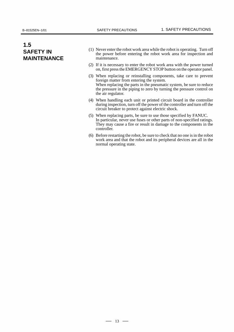
(1) Never enter the robot work area while the robot is operating. Turn offthe power before entering the robot work area for inspection andmaintenance.
(2) If it is necessary to enter the robot work area with the power turnedon, first press the EMERGENCY STOP button on the operator panel.
(3) When replacing or reinstalling components, take care to preventforeign matter from entering the system.When replacing the parts in the pneumatic system, be sure to reducethe pressure in the piping to zero by turning the pressure control onthe air regulator.
(4) When handling each unit or printed circuit board in the controllerduring inspection, turn off the power of the controller and turn off thecircuit breaker to protect against electric shock.
(5) When replacing parts, be sure to use those specified by FANUC.In particular, never use fuses or other parts of non-specified ratings.They may cause a fire or result in damage to the components in thecontroller.
(6) Before restarting the robot, be sure to check that no one is in the robotwork area and that the robot and its peripheral devices are all in thenormal operating state.
1.5SAFETY INMAINTENANCE

1. SAFETY PRECAUTIONS B--81525EN--1/01SAFETY PRECAUTIONS
14
Do not step on or climb the robot or controller as it may adversely affectthe robot or controller and you may get hurt if you lose your footing aswell.
(1) Step--on prohibitive label
Fig.1.6 (a) Step--on Prohibitive Label
Be cautious about a section where this label is affixed, as the sectiongenerates heat. If you have to inevitably touch such a section when it ishot, use a protective provision such as heat--resistant gloves.
(2) High--temperature warning label
Fig.1.6 (b) High--Temperature Warning Label
A high voltage is applied to the places where this label is attached.Before starting maintenance, turn the power to the control unit off, thenturn the circuit breaker off to avoid electric shock hazards. Be careful withservo amplifier and other units because high--voltage places in these unitsmay remain in the high--voltage state for a fixed time.
1.6WARNING LABELDescription
Description
Description

B--81525EN--1/01 1. SAFETY PRECAUTIONSSAFETY PRECAUTIONS
15
(3) High--voltage warning label
Fig.1.6 (c) High--Voltage Warning Label
There may be a high voltage in a place with this label. Before workingon such a portion, turn off the power to the controller and set its circuitbreaker to the off position to avoid shock hazards.In addition, be careful about servo amplifiers and other electric circuitsbecause a high voltage may remain in them for a certain period of timeafter the power is turned off.
Description

II MAINTENANCE
B--81525EN--1/01 1. OVERVIEWMAINTENANCE
19
1 OVERVIEW
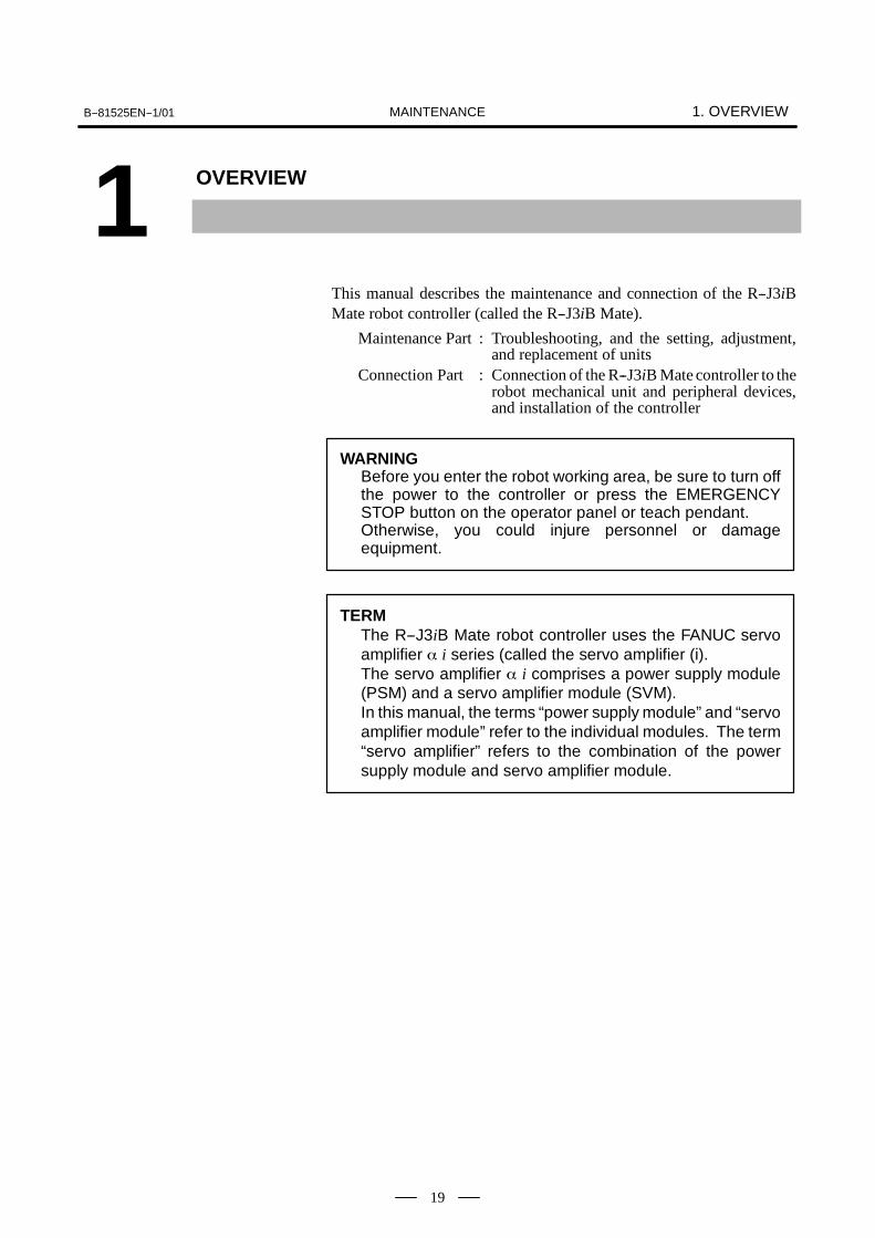
This manual describes the maintenance and connection of the R--J3iBMate robot controller (called the R--J3iB Mate).
Maintenance Part : Troubleshooting, and the setting, adjustment,and replacement of units
Connection Part : Connection of the R--J3iB Mate controller to therobot mechanical unit and peripheral devices,and installation of the controller
WARNINGBefore you enter the robot working area, be sure to turn offthe power to the controller or press the EMERGENCYSTOP button on the operator panel or teach pendant.Otherwise, you could injure personnel or damageequipment.
TERMThe R--J3iB Mate robot controller uses the FANUC servoamplifier α i series (called the servo amplifier (i).The servo amplifier α i comprises a power supply module(PSM) and a servo amplifier module (SVM).In this manual, the terms “power supply module” and “servoamplifier module” refer to the individual modules. The term“servo amplifier” refers to the combination of the powersupply module and servo amplifier module.

2. CONFIGURATION B--81525EN--1/01MAINTENANCE
20
2 CONFIGURATION

B--81525EN--1/01 2. CONFIGURATIONMAINTENANCE
21
The appearance and components might slightly differ depending on thecontrolled robot, application, and options used.Fig.2.1 (a) shows the view of R--J3iB Mate.Fig.2.1 (b) shows the R--J3iB Mate consists of the R--J3iB Mate controller.
Teach pendant
Operatorpanel
R--J3iB Mate controller
Teach pendantcable
Fan unit
ON/OFF handle
Fig.2.1 (a) External View of the R--J3iB Mate Controller
2.1EXTERNAL VIEW OFTHE CONTROLLER

2. CONFIGURATION B--81525EN--1/01MAINTENANCE
22
Robot controller P.C. boardOption slot
Back plane
Servo amplifier module2 (AMP2)Servo amplifier module1 (AMP1)
Power supply module (PSM)AC reactle
Teach pendantEnable/disable switch Emergency stop
button
Power supply transformerfor brake
Power supply unitEmergency stop unit
Emergency stop P.C.board
Heat exchangeEmergency stopbutton
Mode switch
Fig.2.1 (b) R--J3iB Mate interior (Front)
Circut protector(on/off switch) Noise filter
Circuit protector
MCC
Transformer
Fig.2.1 (c) R--J3iB Mate interior (Side)

B--81525EN--1/01 2. CONFIGURATIONMAINTENANCE
23
Table 2.1 Servo amplifier specifications
Robot Power supply module Servo amplifier module1 Servo amplifier module2
LR Mate 100iB
A06B--6115--H001(αPSMR--1i)
A06B--6114--H205(αSVM--20/20i)
A06B--6114--H302(αSVM--10/10/10i)
LR Mate 100iB L M L M NJ1 J2 J3 J4 J5
LR Mate 200iB
A06B--6115--H001(αPSMR--1i)
A06B--6114--H302(αSVM--10/10/10i)
A06B--6114--H302(αSVM--10/10/10i)
LR Mate 200iB L M N L M NJ1 J2 J3 J4 J5 J6

2. CONFIGURATION B--81525EN--1/01MAINTENANCE
24
-- Robot control printed circuit boardThis board is equipped with a microprocessor and its peripheralcircuitry, memory, and operator panel control circuit. A servo controlcircuit is also included.
-- Emergency stop unit, emergency stop printed circuit boardThis unit controls the emergency stop system, magnetic contactor(MCC) of the servo amplifier, and brake. The unit contains the powersupply unit for converting the AC power to the DC power.
-- Backplane printed circuit board
Various control boards are mounted on the backplane PC board.-- Teach pendant
This unit is used to carry out all operations including robotprogramming. The liquid crystal display (LCD) of this unit displaysthe status of the control unit, data, and the like.
-- Servo amplifierThe servo amplifier amplifies the power of the servo amplifier andcontrols the pulse coder.
-- MCCThe MCC controls the main power of the servo amplifier.
-- Operator panelThe operator panel has a port for the serial interface to an externaldevice. The panel also has an EMERGENCY STOP button.
-- TransformerThe transformer converts the input power into the AC voltagerequired for the control unit.
-- Fan unit, heat exchangerThese components are used to cool the inside of the control unit.
-- Circuit protectorThis component turns on or off the power.The input power is connected to the circuit protector in order toprotect the equipment from a large current that could result from aproblem in the electric system of the control unit or an abnormal inputpower.
2.2COMPONENTFUNCTIONS

B--81525EN--1/01 2. CONFIGURATIONMAINTENANCE
25
Daily maintenance and periodic maintenance/inspection ensure reliablerobot performance for extended periods of time.
(1) Daily maintenanceBefore operating the system each day, clean each part of the systemand check the system parts for any damage or cracks. Also check thefollowing:(a) Before service operation
Check the cable connected to the teach pendant for excessivetwisting. Check the controller and peripheral devices forabnormalities.
(b) After service operationAt the end of service operation, return the robot to the specifiedposition, then turn off the controller. Clean each part, and checkfor any damage or cracks. If the ventilation port of the controlleris dusty, clean it.
(c) Check after one monthCheck that the fan is rotating normally. If the fan has dirt and dustbuilt up, clean the fan according to step (d) described below forinspection to be performed every 6 months.
(d) Periodic inspection performed every six monthsRemove the top cover, louver, and back panel (if possible), thenremove any dirt and dust from the inside of the transformercompartment. Wipe off dirt and dust from the fan andtransformer.
(2) Maintenance toolsThe following maintenance tools are recommended:(a) Measuring instruments
AC/DC voltmeter (A digital voltmeter is sometimes required.)Oscilloscope with a frequency range of 5 MHz or higher, twochannels
(b) ToolsPhillips screwdrivers : Large, medium, and smallStandard screwdrivers: Large, medium, and smallNut driver set (Metric)PliersNeedle-nose pliersDiagonal cutting pliers
2.3PREVENTIVEMAINTENANCE

3. TROUBLESHOOTING B--81525EN--1/01MAINTENANCE
26
3 TROUBLESHOOTING
This chapter describes the checking method and corrective action for eacherror code indicated if a hardware alarm occurs. Refer to the operator’smanual to release program alarms.

B--81525EN--1/01 3. TROUBLESHOOTINGMAINTENANCE
27
Check and Corrective action Figure
(Check 1) Check that the circuit protector is on andhas not tripped.
Circuit protector(Correctiveaction)
Turn on the circuit protector.Circuit protector(on/off switch)
(Check 2) Check that the door fan unit and the fanmotor of the heat exchanger are rotatingand that the LED indication on the powersupply module is “--”.
Heat exchange forfan unit (door face)
LED of the power supply module
(Correctiveaction)
If the fan motor is not rotating or if theLED of the power supply module is notglowing, the fuse on the back of the doormay have been blown.-- Check the fuse on the back of the
door.If the fuse on the back of the door hasbeen blown, replace the fuse.
Circuit protector
Transformer unit
3.1POWER CANNOT BETURNED ON
3. TROUBLESHOOTING B--81525EN--1/01MAINTENANCE
28
Check and Corrective action Figure
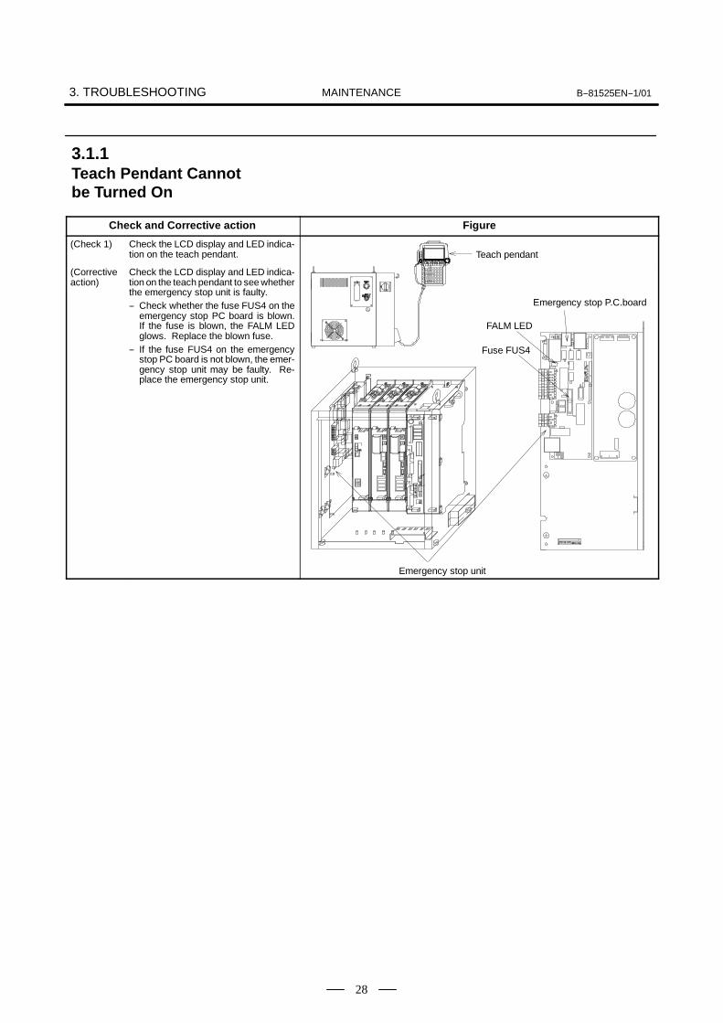
(Check 1) Check the LCD display and LED indica-tion on the teach pendant. Teach pendant
(Correctiveaction)
Check the LCD display and LED indica-tion on the teach pendant to see whetherthe emergency stop unit is faulty.-- Check whether the fuse FUS4 on the
emergency stop PC board is blown.If the fuse is blown, the FALM LEDglows. Replace the blown fuse.
-- If the fuse FUS4 on the emergencystop PC board is not blown, the emer-gency stop unit may be faulty. Re-place the emergency stop unit.
p
Emergency stop P.C.board
Fuse FUS4
FALM LED
Emergency stop unit
3.1.1Teach Pendant Cannotbe Turned On

B--81525EN--1/01 3. TROUBLESHOOTINGMAINTENANCE
29
Check and Corrective action Figure
(Check 1) Check that the “.” portion of the seven--segment LED glows on the robot control-ler PC board.
(Correctiveaction)
If the “.” portion is not glowing, the fuseFUS1 on the robot controller PC boardmay be blown. Alternatively, the DC/DCconverter module may be damaged.If the FUSE ALARM LED is glowing, thefuse FUS1 may be blown.The fuse FUS1 is provided on the robotcontroller PC board. Before checkingthe fuse, turn off the circuit protector.a) If the fuse FUS1 has been blown-- See Corrective action (1).b) If the fuse FUS1 is not blown-- See Corrective action (2).
+24V inputconnectorCP5
(Correctiveaction(1))
Cause of the blowing of the fuse FUS1and corrective actiona) Check whether the device which is
connected to the RS--232--C/RS--422 port and requires the powersupply of +24 V is sound.
b) Problem in the DC/DC convertermoduleIf the DC/DC converter module getsfaulty in the short--circuit mode,FUS1 is blown.Replace the DC/DC converter mod-ule.
DC/DC convertermodule
dot part of sevensegment LED
(Correctiveaction(2)) a) Problem in the DC/DC converter
moduleReplace the DC/DC converter mod-ule.
b) Problem in the robot controller PCboardReplace the robot controller PCboard. (For the LED indications, seeSection 3.7, “TROUBLESHOOTINGUSING LEDS.”)
FUS1 7.5ADC24V input fuse
3.1.2Initial Screen Remainson the Teach Pendant
3. TROUBLESHOOTING B--81525EN--1/01MAINTENANCE
30
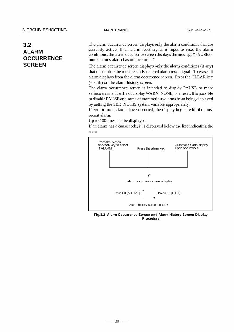
The alarm occurrence screen displays only the alarm conditions that arecurrently active. If an alarm reset signal is input to reset the alarmconditions, the alarm occurrence screen displays the message “PAUSE ormore serious alarm has not occurred.”
The alarm occurrence screen displays only the alarm conditions (if any)that occur after the most recently entered alarm reset signal. To erase allalarm displays from the alarm occurrence screen. Press the CLEAR key(+ shift) on the alarm history screen.The alarm occurrence screen is intended to display PAUSE or moreserious alarms. It will not display WARN, NONE, or a reset. It is possibleto disable PAUSE and some of more serious alarms from being displayedby setting the $ER_NOHIS system variable appropriately.If two or more alarms have occurred, the display begins with the mostrecent alarm.Up to 100 lines can be displayed.If an alarm has a cause code, it is displayed below the line indicating thealarm.
Press the screenselection key to select[4 ALARM]. Press the alarm key.
Automatic alarm displayupon occurrence
Alarm occurrence screen display
Press F3 [ACTIVE]. Press F3 [HIST].
Alarm history screen display
Fig.3.2 Alarm Occurrence Screen and Alarm History Screen DisplayProcedure
3.2ALARMOCCURRENCESCREEN

B--81525EN--1/01 3. TROUBLESHOOTINGMAINTENANCE
31
Displaying the alarm history/alarm detail information
(1) Press the MENUS key to display the screen menu.
(2) Select [ALARM].You will see a screen similar to the following
MENUS
34 ALARM5 I/O
INTP-224 (SAMPLE1, 7) Jump label is failMEMO-027 Specified line does not existAlarm JOINT 30 %
1/251 INTP-224 (SAMPLE1, 7) Jump label is2 SRVO-002 Teach pendant E-stop3 R E S E T4 SRVO-027 Robot not mastered(Group:1)5 SYST-026 System normal power up
[ TYPE ] CLEAR HELP
NOTEThe latest alarm is assigned number 1. To view messagesthat are currently not on the screen, press the F5, HELP,then press the right arrow key.
(3) To display the alarm detail screen, press F5, [HELP].
CLEAR HELP
F5
INTP-224 (SAMPLE1, 7) Jump label is fail
INTP-224 (SAMPLE1, 7) Jump label is failMEMO-027 Specified line does not exist30-MAY-44 07:15STOP.L 00000110Alarm
1/251 INTP-224 (SAMPLE1, 7) Jump label is2 SRVO-002 Teach pendant E-stop
[ TYPE ] CLEAR HELP
(4) To return to the alarm history screen, press the PREV key.
PREV
(5) To delete all the alarm histories, press and hold down the SHIFT key,then press F4, [CLEAR].
NOTEWhen system variable $ER_NOHIS = 1, NONE alarms orWARN alarms are not recorded. When $ER_NOHIS=2,resets are not recorded in the alarm history. When$ER_NOHIS=3, resets, WARN alarms, and NONE alarmsare not recorded.
CLEAR HELP
F4SHIFT
Step

3. TROUBLESHOOTING B--81525EN--1/01MAINTENANCE
32
The following map indicates teach pendant operations used to check analarm.
4 ALARM
F1 [TYPE]
Alarm : Active
F1 [TYPE]
F3 HIST
Alarm : HIST
F1 [TYPE]
F3 [ACTIVE]
F4 CLEAR
F5 HELP
DETAIL Alarm
F1 [TYPE]
F3 [ACTIVE]
F4 CLEAR
F5 HELP

B--81525EN--1/01 3. TROUBLESHOOTINGMAINTENANCE
33
The safety signal screen indicates the state of signals related to safety. Tobe specific, the screen indicates whether each safety signal is currently on.On this screen, it is impossible to change the state of any safety signal.
Table 3.3 Safety Signals
Safety signal Description
Operator panel emergency stop This item indicates the state of the emergency stop button on the operator panel. If theEMERGENCY STOP board is pressed, the state is indicated as “TRUE”.
Teach pendant emergency stop This item indicates the state of the emergency stop button on the teach pendant. If theEMERGENCY STOP board is pressed, the state is indicated as “TRUE”.
External emergency stop This item indicates the state of the external emergency stop signal. If the EMERGENCYSTOP signal is input, the state is indicated as “TRUE”.
Fence open This item indicates the state of the safety fence. If the safety fence is open, the state isindicated as “TRUE”.
Deadman switch This item indicates whether the DEADMAN switch on the teach pendant is grasped. Ifthe teach pendant is operable, and the DEADMAN switch is grasped, the state is indi-cated as “TRUE”. If the deadman switch is released when the teach pendant is operable,an alarm occurs, causing the servo power to be switched off.
Teach pendant operable This item indicates whether the teach pendant is operable. If the teach pendant is oper-able, the state is indicated as “TRUE”.
Hand broken This item indicates the state of the hand safety joint. If the hand interferes with a work-piece or anything like this, and the safety joint is opened, the state is indicated as“TRUE”. In this case, an alarm occurs, causing the servo power to be switched off.
Robot overtravel This item indicates whether the current position of the robot is out of the operation range.If any robot articulation goes out of the operation range beyond the overtravel switch, thestate is indicated as “TRUE”. In this case, an alarm occurs, causing the servo power to beswitched off.
Abnormal air pressure This item indicates the state of the air pressure. The abnormal air pressure signal is con-nected to the air pressure sensor. If the air pressure is not higher than the specifiedvalue, the state is indicated as “TRUE”.
(1) Press the MENUS key to display the screen menu.
(2) Select STATUS on the next page.
(3) Press F1, [TYPE] to display the screen switching menu.
(4) Select Safety Signal. You will see a screen similar to the following.
SYSTEM Safety JOINT 30%
SIGNAL NAME STATUS 1/11
1 SOP E-Stop: FALSE2 TP E-stop: FALSE3 Ext E-Stop: FALSE4 Fence Open: FALSE5 TP Deadman: TRUE6 TP Enable: TRUE7 Hand Broken: FALSE8 Over Travel: FALSE9 Low Air Alarm: FALSE
[TYPE]
3.3SAFETY SIGNALS
Step

3. TROUBLESHOOTING B--81525EN--1/01MAINTENANCE
34
Mastering is needed if:
(1) The SRVO 062 BZAL or SRVO 038 pulse mismatch alarm occurs,or
(2) The pulse coder is replaced.
Item (1) requires simplified mastering, while item (2) requireszero--degree or jig position mastering. (Zero--degree position masteringis just for quick--fix purposes. After zero--degree position mastering isused, jig position mastering should be performed later.)The mastering procedure is described below. For details, refer to anapplicable maintenance manual of mechanical unit or operator’s manualof control unit.
System variable $MASTER_ENB must be set to 1 or 2.
SYSTEM Variables JOINT 10%57/136
57 $MASTER_ENB 1
(1) Press <MENUS>.
(2) Select SYSTEM.
(3) Press F1, TYPE.
(4) Select Master/Cal you will see a screen similar to the following.
F1
Master/Cal
TYPE
SYSTEM Master/Cal JOINT 30%
1 FIXTURE POSITION MASTER
2 ZERO POSITION MASTER3 QUICK MASTER4 SINGLE AXIS MASTER5 SET QUICK MASTER REF6 CALIBRATE
Press ’ENTER’ or number key to select.
[TYPE] LOAD RES_PCA DONE
5 POSITION6 SYSTEM7
MENUS
9 USER0 -- NEXT --
(5) Move the robot by jog feed to the mastering position. Release thebrake on the manual brake control screen if necessary.
NOTEMastering can not be performed until the axis is rotatedenough to establish a pulse.
3.4MASTERING
Condition
Step

B--81525EN--1/01 3. TROUBLESHOOTINGMAINTENANCE
35
(6) Select “1 FIXTURE POSITION MASTER” and press the F4 key(yes). Mastering data is set.
F4
SYSTEM Master/Cal
1 FIXTURE POSITION MASTER2 ZERO POSITION MASTERMaster at master position? [NO]
ENTER
Master at master position? [NO][ TYPE ] YES NO
SYSTEM Master/Cal JOINT 30 %
1 FIXTURE POSITION MASTER2 ZERO POSITION MASTER3 QUICK MASTER4 SINGLE AXIS MASTER5 SET QUICK MASTER REF6 CALIBRATE
Robot Mastered! Mastering Data:<0> <11808249> <38767856><9873638> <122000309> <2000319>
[ TYPE ] LOAD RES_PCA DONE
(7) Select “6 CALIBRATE” and press the F4 key (yes). Calibration isperformed.Alternatively, to perform positioning, turn the power off, then turn iton again. Calibration is performed whenever the power is turned on.
F4
5 SET QUICK MASTER REF6 CALIBRATECalibrate? [NO] ENTER
Calibrate? [NO][ TYPE ] YES NO
SYSTEM Master/Cal JOINT 30 %
1 FIXTURE POSITION MASTER2 ZERO POSITION MASTER3 QUICK MASTER4 SINGLE AXIS MASTER5 SET QUICK MASTER REF6 CALIBRATE
Robot Calibrated! Cur Jnt Ang(deg):<10.000> <-25.000> <40.000><5.000> <-15.000> <0.000>
[ TYPE ] LOAD RES_PCA DONE
(8) Press F5 “DONE”, after mastering.
F5
DONE

3. TROUBLESHOOTING B--81525EN--1/01MAINTENANCE
36
(1) SRVO--001 SVAL1 Operator panel E--stop(Explanation) The EMERGENCY STOP button on the operator
panel is pressed.(Action 1) Release the emergency stop button pressed on the
operator panel.(Action 2) Release the EMERGENCY STOP button on the
operator panel.(Action 3) Replace the emergency stop unit.
Before taking (Action 4), make a backup copy of allthe programs and settings of the control unit.
(Action 4) Replace the robot controller PC board.
Emergency stop button
Emergency stop unit
Robot controller P.C. board
Operatorpanel
Fig.3.5 (1) (a) SRVO--001 SVAL1 Operator panel E--stop
3.5TROUBLESHOOTINGUSING THE ERRORCODE

B--81525EN--1/01 3. TROUBLESHOOTINGMAINTENANCE
37
(2) SRVO--002 SVAL1 Teach pendant E--stop(Explanation) The emergency stop button on the operator’s Teach
Pendant was pressed.(Action 1) Release the emergency stop button on the teach
pendant.(Action 2) Replace Teach Pendant.
Emergency stop button
Fig.3.5 (2) SRVO--002 SVAL1 Teach pendant E--stop
(3) SRVO--003 SVAL1 Deadman switch released(Explanation) The teach pendant is enabled, but the deadman switch
is not pressed.(Action 1) Press the deadman switch to run the robot.(Action 2) Replace the teach pendant.
Deadman switch
Fig.3.5 (3) SRVO--001 SVAL1 Deadman switch released
3. TROUBLESHOOTING B--81525EN--1/01MAINTENANCE
38
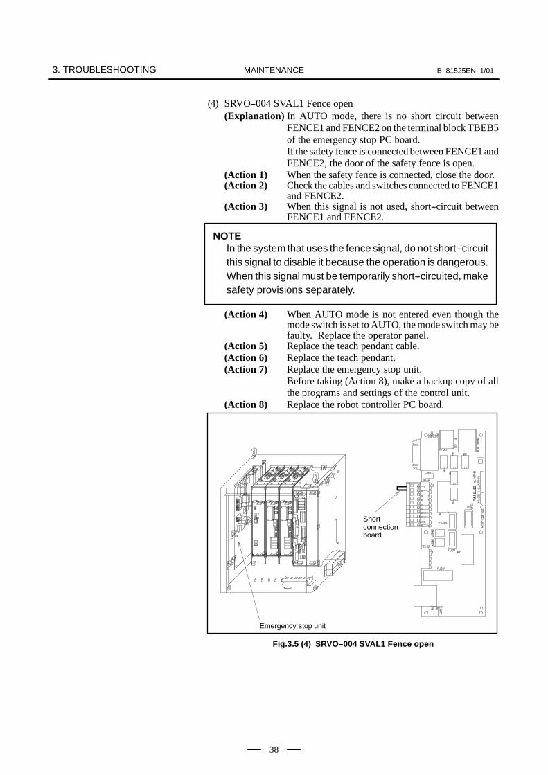
(4) SRVO--004 SVAL1 Fence open(Explanation) In AUTO mode, there is no short circuit between
FENCE1 and FENCE2 on the terminal block TBEB5of the emergency stop PC board.If the safety fence is connected between FENCE1 andFENCE2, the door of the safety fence is open.
(Action 1) When the safety fence is connected, close the door.(Action 2) Check the cables and switches connected to FENCE1
and FENCE2.(Action 3) When this signal is not used, short--circuit between
FENCE1 and FENCE2.
NOTEIn the system that uses the fence signal, do not short--circuitthis signal to disable it because the operation is dangerous.When this signal must be temporarily short--circuited, makesafety provisions separately.
(Action 4) When AUTO mode is not entered even though themode switch is set to AUTO, the mode switch may befaulty. Replace the operator panel.
(Action 5) Replace the teach pendant cable.(Action 6) Replace the teach pendant.(Action 7) Replace the emergency stop unit.
Before taking (Action 8), make a backup copy of allthe programs and settings of the control unit.
(Action 8) Replace the robot controller PC board.
Emergency stop unit
Shortconnectionboard
Fig.3.5 (4) SRVO--004 SVAL1 Fence open

B--81525EN--1/01 3. TROUBLESHOOTINGMAINTENANCE
39
(5) SRVO--005 SVAL1 Robot overtravel(Explanation) This alarm should not occur because no overtravel
input signal is provided. However, this alarm can becaused by an abnormal overtravel input signal acrossthe robot interconnection cable and robot controllerPC board.
(Action 1) Check the robot interconnection cable (RMP) for thefollowing.1) The male and female connection pins are not
twisted or are not loose.2) The connector is securely connected.3) The cable is free from a break and ground fault.Next, check that the connector CRM82 of the robotcontroller PC board is securely connected. Inaddition, check that the RMP cable is sound and freefrom a break or visible twist.Before taking (Action 2), make a backup copy of allthe programs and settings of the control unit.
(Action 2) Replace the robot controller PC board.
Robot controller P.C. board
Fig.3.5 (5) SRVO--005 SVAL1 Robot overtravel

3. TROUBLESHOOTING B--81525EN--1/01MAINTENANCE
40
(6) SRVO--006 SVAL1 Hand broken(Explanation) The safety joint, if any, is broken. If no joint is
broken, the HBK signal line of the robotinterconnection cable has a break or ground fault.
(Action 1) Holding down the shift key, press the alarm releasebutton. This releases the alarm. Keeping on holdingdown the shift key, carry out jog feed to move the toolto the work area.1) Replace the safety joint.2) Examine the cable.
(Action 2) Check the robot interconnection cable (RMP) for thefollowing.1) The male and female connection pins are not
twisted or are not loose.2) The connector is securely connected.3) The cable is free from a break and ground fault.Next, check that the connector CRM82 of the robotcontroller PC board is securely connected. Inaddition, check that the RMP cable is sound and freefrom a break or visible twist.Before taking (Action 3), make a backup copy of allthe programs and settings of the control unit.
(Action 3) Replace the robot controller PC board.
Robot controller P.C. board
Fig.3.5 (6) SRVO--006 SVAL1 Hand broken

B--81525EN--1/01 3. TROUBLESHOOTINGMAINTENANCE
41
(7) SRVO--007 SVAL1 External E--stop(Explanation) EMGIN1 and EMGIN2 on the terminal blockTBEB5
of the emergency stop PC board are notshort--circuited. If an external emergency stop switchis connected across EMGIN1 and EMGIN2, theswitch has been pressed.
(Action 1) If an external emergency stop switch is connected,releases the switch.
(Action 2) Check the switch and cable connected to EMGIN1and EMGIN2.
(Action 3) When this signal is not used, make a connectionbetween EMGIN1 and EMGIN2. (WARNING)
(Action 4) Replace the emergency stop unit.
WARNINGDo NOT short--circuit, or disable, this signal in a system inwhich the External emergency stop input signal is in use, asit is very dangerous. If it is necessary to run the robot byshort--circuiting the signal even temporarily, an additionalsafety provision must be provided.
Emergency stop unit
Shortconnectionboard
Fig.3.5 (7) SRVO--007 SVAL1 External E--stop
3. TROUBLESHOOTING B--81525EN--1/01MAINTENANCE
42
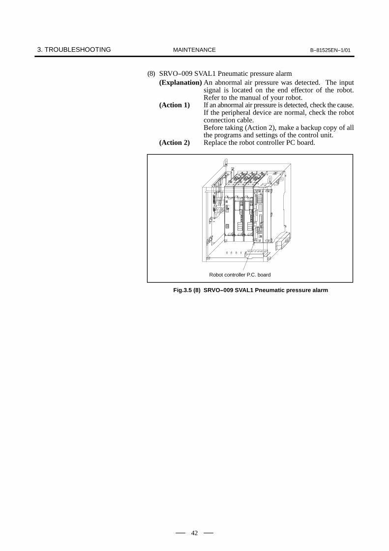
(8) SRVO--009 SVAL1 Pneumatic pressure alarm(Explanation) An abnormal air pressure was detected. The input
signal is located on the end effector of the robot.Refer to the manual of your robot.
(Action 1) If an abnormal air pressure is detected, check the cause.If the peripheral device are normal, check the robotconnection cable.Before taking (Action 2), make a backup copy of allthe programs and settings of the control unit.
(Action 2) Replace the robot controller PC board.
Robot controller P.C. board
Fig.3.5 (8) SRVO--009 SVAL1 Pneumatic pressure alarm

B--81525EN--1/01 3. TROUBLESHOOTINGMAINTENANCE
43
(9) SRVO--014 WARN Fan motor abnormal(Explanation) A fan motor in the backplane unit is abnormal.(Action) Check the fan motor and its cables. Replace them if
necessary.
Fan motor
Fig.3.5 (9) SRVO--014 WARN Fan motor abnormal

3. TROUBLESHOOTING B--81525EN--1/01MAINTENANCE
44
(10)SRVO--015 SVAL1 SYSTEM OVER HEAT (Group : i Axis : j)(Explanation) The temperature in the control unit exceeds the
specified value.(Action 1) If the ambient temperature is higher than specified
(45°C), cool down ambient temperature.(Action 2) If the fan motor is not running, check it and its cables.
Replace them if necessary.(Action 3) If the thermostat on the robot controller PC board is
defective, replace the robot controller PC board.
Fan motor(on the heat exchange)
Fan motor (door face) Robot controller P.C. board
Fig.3.5 (10) SRVO--015 SVAL1 SYSTEM OVER HEAT
B--81525EN--1/01 3. TROUBLESHOOTINGMAINTENANCE
45
(11) SRVO--021 SVAL1 SRDY off (Group : i Axis : j)(Explanation) The HRDY is on and the SRDY is off, although there
is no other cause of an alarm. (HRDY is a signal withwhich the host directs the servo system whether toturn on or off the servo amplifier magnetic contactor.SRDY is a signal with which the servo systeminforms the host whether the magnetic contactor isturned on.)If the servo amplifier magnetic contactor cannot beturned on when directed so, it is most likely that aservo amplifier alarm has occurred. If a servoamplifier alarm has been detected, the host will notissue this alarm (SRDY off). Therefore, this alarmindicates that the magnetic contactor cannot be turnedon for an unknown reason.
(Action 1) Measure the voltage of the 200--VAC input to thepower supply module. If the voltage is 170 VAC orlower, adjust the input voltage.
(Action 2) Check that CRR78 of the emergency stop PC boardand CX3 and CX4 of the power supply module aresecurely connected. Check the cables of theemergency stop PC board and power supply modulefor a break.
(Action 3) Check the EMERGENCY STOP line (teach pendantemergency stop, teach pendant enable/disable switch,teach pendant deadman switch, operator panelemergency stop, external emergency stop input, fenceinput, servo off--input) for a possibility of aninstantaneous interruption. If the software cannotjudge the cause of the alarm at an instantaneousinterruption of the EMERGENCY STOP line, thisalarm occurs.
(Action 4) Replace the emergency stop unit.(Action 5) If an alarm occurs on all axes, the power supply
module may be faulty. Replace the power supplymodule.
(Action 6) If an alarm occurs on a particular axis, the servoamplifier module may be faulty. Replace the servoamplifier module controlling the axis.
(Action 7) Replace the axis control card on the robot controllerPC board.

3. TROUBLESHOOTING B--81525EN--1/01MAINTENANCE
46
Robot controller P.C. boardServo amplifier module
Power supply module
Emergency stop unit
Axis control card
Fig.3.5 (11) SRVO--021 SVAL1 SRDY off

B--81525EN--1/01 3. TROUBLESHOOTINGMAINTENANCE
47
(12)SRVO--022 SVAL1 SRDY on (Group : i Axis : j)(Explanation) When the HRDY is about to go on, the SRDY is already
on. (HRDY is a signal with which the host directs theservo system whether to turn on or off the servoamplifier magnetic contactor. SRDY is a signal withwhich the servo system informs the host whether themagnetic contactor is turned on.
(Action 1) Replace the axis control card on the robot controllerPC board.
(Action 2) If an alarm occurs on all axes, the power supplymodule may be faulty. Replace the power supplymodule.
(Action 3) If an alarm occurs on a particular axis, the servoamplifier module may be faulty. Replace the servoamplifier module controlling the axis.
Robot controller P.C. boardServo amplifier module
Power supply moduleAxis control card
Fig.3.5 (12) SRVO--022 SVAL1 SRDY on

3. TROUBLESHOOTING B--81525EN--1/01MAINTENANCE
48
(13)SRVO--023 SVAL1 Stop error excess (Group : i Axis : j)(Explanation) When the servo is at stop, the position error is
abnormally large.(Action 1) Check whether the motor brake has been released.(Action 2) Make sure that the servo amplifier CZ2L to N are
connected tightly.(Action 3) Check to see if the load is greater than the rating. If
greater, reduce it to within the rating. (If the load istoo greater, the torque required for acceleration /deceleration becomes higher than the capacity of themotor. As a result, the motor becomes unable tofollow the command, and an alarm is issued.)
(Action 4) Check each phase voltage of the CZ1 connector of thethree--phase power (200 VAC) input to the servoamplifier. If it is 170 VAC or lower, check the linevoltage. (If the voltage input to the servo amplifierbecomes low, the torque output also becomes low. Asa result the motor may become unable to follow thecommand, hence possibly an alarm.)
(Action 5) If the line voltage is 170 VAC or higher, replace thepower supply module or servo amplifier module.
(Action 6) Check disconnection of robot connection cable(RMP).
(Action 7) Replace the motor.
Servo amplifier modulePower supply module
Fig.3.5 (13) SRVO--023 SVAL1 Stop error excess

B--81525EN--1/01 3. TROUBLESHOOTINGMAINTENANCE
49
(14)SRVO--024 SVAL1 Move error excess (Group : i Axis : j)(Explanation) When the robot is running, its position error is greater
than a specified value ($PARAM _ GROUP.$MOVER _ OFFST or $PARAM _ GROUP.$TRKERRLIM). It is likely that the robot cannotfollow the speed specified by program.
(Action 1) Check the robot for binding axis.(Action 2) Take the same actions as described for the above
alarm.(15)SRVO--025 SVAL1 Motn dt overflow (Group : i Axis : j)
(Explanation) The specified value is too great.(16)SRVO--026 WARN2 Motor speed limit (Group : i Axis : j)
(Explanation) A value higher than the maximum motor speed($PARAM_GROUP.$MOT_SPD_LIM) wasspecified. The actual motor speed is clamped to themaximum speed.
(17)SRVO--027 WARN Robot not mastered (Group : i)(Explanation) An attempt was made to calibrate the robot, but the
necessary adjustment had not been completed.(Action) Master the robot.
(18)SRVO--030 SVAL1 Brake on hold (Group : i)(Explanation) This alarm occurs when the robot pauses, if the brake
on hold function has been enabled ($SCR.$BRKHOLD _ ENB = 1). Disable the function if it isnot necessary.
(Action) Disable [Servo--off during pause] on the generalsetting menu (Select Setting general).
(19)SRVO--031 SVAL1 User servo alarm (Group : i)(Explanation) An user servo alarm occurred.
(20)SRVO--033 WARN Robot not calibrated (Group : i)(Explanation) An attempt was made to set up a reference point for
simplified adjustment, but the robot had not beencalibrated.
(Action) Calibrate the robot.1.Supply power.2.Set up a simplified adjustment reference point
using [Positioning] on the positioning menu.(21)SRVO--034 WARN Ref pos not set (Group : i)
(Explanation) An attempt was made to perform simplifiedadjustment,but the reference point had not been set up.
(Action) Set up a simplified adjustment reference point on thepositioning menu.
(22)SRVO--035 WARN2 Joint speed limit (Group : i Axis : j)(Explanation) A value higher than the maximum axis speed
($PARAM_GROUP.$JNTVELLIM) was specified.Each actual axis speed is clamped to the maximumspeed.
(23)SRVO--036 SVAL1 Inpos time over (Group : i Axis : j)(Explanation) The robot did not get to the effective area ($PARAM _
GROUP.$ STOPTOL) even after the position checkmonitoring time ($PARAM _ GROUP. $INPOS _TIME) elapsed.
(Action) Take the same actions as for SRVO--23 (large positionerror at a stop).
(24)SRVO--037 SVAL1 Imstp input (Group : i)(Explanation) The *IMSTP signal for a peripheral device interface
was input.(Action) Turn on the *IMSTP signal.

3. TROUBLESHOOTING B--81525EN--1/01MAINTENANCE
50
(25)SRVO--038 SVAL2 Pulse mismatch (Group : i Axis : j)(Explanation) The pulse count obtained when power is turned off
does not match the pulse count obtained when poweris applied. This alarm is asserted after exchange thepulsecoder or battery for back up of the pulsecoderdata or loading back up data to the Robot controllerPC board.
(Action) Perform Absolute Pulse Coder reset and remasterrobot (RES--PCA)1. Press MENUS.2. Select SYSTEM.3. Press F1 [TYPE].4. Select MASTER/CAL.5. Press F3, PES--PCA and YES.6. Execute machining.7. Press RESET.
The fault condition should reset. If the controlleris still faulted with additional servo--relatederrors,cold start the controller.It might be necessary to remaster the robot.
(26)SRVO--041 SVAL2 MOFAL alarm (Group : i Axis : j)(Explanation) The servo value was too high.(Action) Cold start the controller.
B--81525EN--1/01 3. TROUBLESHOOTINGMAINTENANCE
51
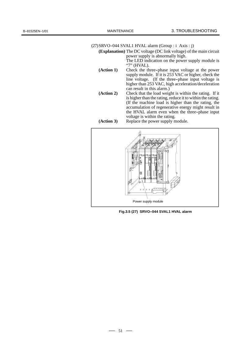
(27)SRVO--044 SVAL1 HVAL alarm (Group : i Axis : j)(Explanation) The DC voltage (DC link voltage) of the main circuit
power supply is abnormally high.The LED indication on the power supply module is“7” (HVAL).
(Action 1) Check the three--phase input voltage at the powersupply module. If it is 253 VAC or higher, check theline voltage. (If the three--phase input voltage ishigher than 253 VAC, high acceleration/decelerationcan result in this alarm.)
(Action 2) Check that the load weight is within the rating. If itis higher than the rating, reduce it to within the rating.(If the machine load is higher than the rating, theaccumulation of regenerative energy might result inthe HVAL alarm even when the three--phase inputvoltage is within the rating.
(Action 3) Replace the power supply module.
Power supply module
Fig.3.5 (27) SRVO--044 SVAL1 HVAL alarm
3. TROUBLESHOOTING B--81525EN--1/01MAINTENANCE
52
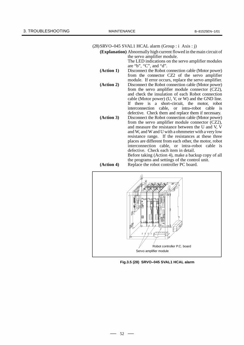
(28)SRVO--045 SVAL1 HCAL alarm (Group : i Axis : j)(Explanation) Abnormally high current flowed in the main circuit of
the servo amplifier module.The LED indications on the servo amplifier modulesare “b”, “C”, and “d”.
(Action 1) Disconnect the Robot connection cable (Motor power)from the connector CZ2 of the servo amplifiermodule. If error occurs, replace the servo amplifier.
(Action 2) Disconnect the Robot connection cable (Motor power)from the servo amplifier module connector (CZ2),and check the insulation of each Robot connectioncable (Motor power) (U, V, or W) and the GND line.If there is a short--circuit, the motor, robotinterconnection cable, or intra--robot cable isdefective. Check them and replace them if necessary.
(Action 3) Disconnect the Robot connection cable (Motor power)from the servo amplifier module connector (CZ2),and measure the resistance between the U and V, Vand W, and W and U with a ohmmeter with a very lowresistance range. If the resistances at these threeplaces are different from each other, the motor, robotinterconnection cable, or intra--robot cable isdefective. Check each item in detail.Before taking (Action 4), make a backup copy of allthe programs and settings of the control unit.
(Action 4) Replace the robot controller PC board.
Robot controller P.C. boardServo amplifier module
Fig.3.5 (28) SRVO--045 SVAL1 HCAL alarm

B--81525EN--1/01 3. TROUBLESHOOTINGMAINTENANCE
53
(29)SRVO--046 SVAL2 OVC alarm (Group : i Axis : j)(Explanation) This alarm is issued to prevent the motor from
thermal damage that might occur when the root meantsquare current calculated within the servo system isout of the allowable range.
(Action 1) Check the operating conditions for the robot and relaxthe service conditions.
(Action 2) Check each phase voltage of the three--phase inputpower (200 VAC for the power supply module. If itis 170 VAC or lower, check the line voltage.
(Action 3) Replace the power supply module and servoamplifier module.
(Action 4) Check the robot connection cable (RMP).(Action 5) Replace the motor.
Servo amplifier modulePower supply module
Fig.3.5 (29) SRVO--046 SVAL2 OVC alarm

3. TROUBLESHOOTING B--81525EN--1/01MAINTENANCE
54
Relationships among the OVC, OVL, and HC alarmsOverviewThis section points out the differences among the OVC, OVL, and HCalarms and describes the purpose of each alarm.Alarm detection section
Abbreviation Designation Detection section
OVC Overcurrent alarm Servo software
OVL Overload alarm Thermal relay in the motor OHAL2Thermal relay in the servo amplifier OHAL1Thermal relay in the separate regenerative dis-charge unit DCAL
HC High current alarm Servo amplifier
Purpose of each alarm1) HC alarm (high current alarm)
If high current flow in a power transistor momentarily due toabnormality or noise in the control circuit, the power transistor andrectifier diodes might be damaged, or the magnet of the motor mightbe degaussed. The HC alarm is intended to prevent such failures.
2) OVC and OVL alarms (overcurrent and overload alarms)The OVC and OVL alarms are intended to prevent overheat that maylead to the burnout of the motor winding, the breakdown of the servoamplifier transistor, and the separate regenerative resistor.The OVL alarm occurs when each built--in thermal relay detects atemperature higher than the rated value. However, this method is notnecessarily perfect to prevent these failures. For example, if themotor frequently repeats to start and stop, the thermal time constantof the motor, which has a large mass, becomes higher than the timeconstant of the thermal relay, because these two components aredifferent in material, structure, and dimension. Therefore, if themotor repeats to start and stop within a short time as shown in Fig.1, the temperature rise in the motor is steeper than that in the thermalrelay, thus causing the motor to burn before the thermal relay detectsan abnormally high temperature.
Temperature
Start StartStartStop Stop
Temperature atwhich the windingstarts to burn
Thermal time constantof the motor is high.
Thermal time constantof the thermal relay islow.
Time
Fig.1 Relationship between the temperatures of the motor and thermal relay on start/stop cycles
To prevent the above defects, software is used to monitor the currentin the motor constantly in order to estimate the temperature of themotor. The OVC alarm is issued based on this estimated temperature.This method estimates the motor temperature with substantialaccuracy, so it can prevent the failures described above.
Reference

B--81525EN--1/01 3. TROUBLESHOOTINGMAINTENANCE
55
To sum up, a double protection method is used; the OVCalarm isusedfor protection from a short--time overcurrent, and the OVL alarm isused for protection from long--term overload. The relationshipbetween the OVC and OVL alarms is shown in Fig 2.
CurrentProtection area forthe motor andservo amplifier
Protection by the OVLLimit current
Protection bythe OVC
Rated continuous current
Time
Fig.2 Relationship between the OVC and OVL alarms
NOTEThe relationship shown in Fig. 2 is taken into considerationfor the OVC alarm. The motor might not be hot even if theOVC alarm has occurred. In this case, do not change theparameters to relax protection.
(30)SRVO--047 SVAL1 LVAL alarm (Group : i Axis : j)(Explanation) The control power voltage (+5 V, etc.) on the servo
amplifier module is too low. The LED indication onthe servo amplifier module is “2” (LVAL).
(Action 1) Replace the servo amplifier module.
Servo amplifier module
Fig.3.5 (30) SRVO--047 SVAL1 LVAL alarm

3. TROUBLESHOOTING B--81525EN--1/01MAINTENANCE
56
(31)SRVO--049 SVAL1 OHAL1 alarm (Group : i Axis : j)(Explanation) This alarm does not occur when the power supply
module and serve amplifier modules used with theR--J3iB Mate are under normal conditions.This alarm indicates that any of the power supplymodule and servo amplifier modules is faulty.
(Action 1) If this alarm occurs in relation to all axes, replace thepower supply module.
(Action 2) If this alarm occurs in relation to a specific axis,replace the servo amplifier module that controls theaxis.
Servo amplifier modulePower supply module
Fig.3.5 (31) SRVO--049 SVAL1 OHAL1 alarm
B--81525EN--1/01 3. TROUBLESHOOTINGMAINTENANCE
57
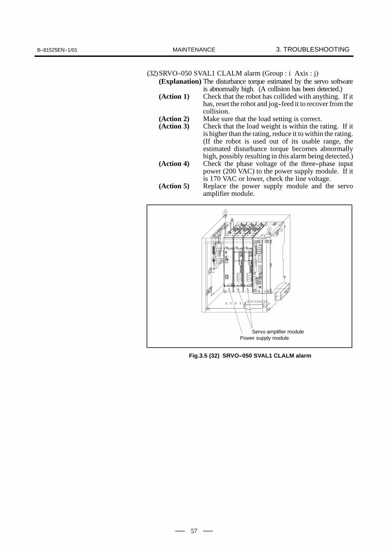
(32)SRVO--050 SVAL1 CLALM alarm (Group : i Axis : j)(Explanation) The disturbance torque estimated by the servo software
is abnormally high. (A collision has been detected.)(Action 1) Check that the robot has collided with anything. If it
has, reset the robot and jog--feed it to recover from thecollision.
(Action 2) Make sure that the load setting is correct.(Action 3) Check that the load weight is within the rating. If it
is higher than the rating, reduce it to within the rating.(If the robot is used out of its usable range, theestimated disturbance torque becomes abnormallyhigh, possibly resulting in this alarm being detected.)
(Action 4) Check the phase voltage of the three--phase inputpower (200 VAC) to the power supply module. If itis 170 VAC or lower, check the line voltage.
(Action 5) Replace the power supply module and the servoamplifier module.
Servo amplifier modulePower supply module
Fig.3.5 (32) SRVO--050 SVAL1 CLALM alarm

3. TROUBLESHOOTING B--81525EN--1/01MAINTENANCE
58
(33)SRVO--051 SVAL2 CUER alarm (Group : i Axis : j)(Explanation) The offset of the current feedback value is abnormally
high.(Action) Replace the servo amplifier module.
Servo amplifier module
Fig.3.5 (33) SRVO--051 SVAL2 CUER alarm

B--81525EN--1/01 3. TROUBLESHOOTINGMAINTENANCE
59
(34)SRVO--054 DSM Memory Error(Explanation) An access to the axis control card on the robot
controller PC board memory fails.(Action) Replace the axis control card.
Robot controller P.C. boardServo amplifier module
Axis control card
Fig.3.5 (34) SRVO--054 DSM Memory Error
3. TROUBLESHOOTING B--81525EN--1/01MAINTENANCE
60
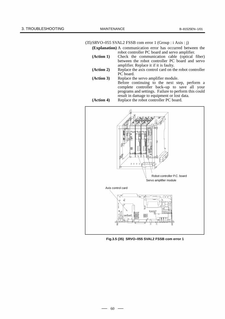
(35)SRVO--055 SVAL2 FSSB com error 1 (Group : i Axis : j)(Explanation) A communication error has occurred between the
robot controller PC board and servo amplifier.(Action 1) Check the communication cable (optical fiber)
between the robot controller PC board and servoamplifier. Replace it if it is faulty.
(Action 2) Replace the axis control card on the robot controllerPC board.
(Action 3) Replace the servo amplifier module.Before continuing to the next step, perform acomplete controller back--up to save all yourprograms and settings. Failure to perform this couldresult in damage to equipment or lost data.
(Action 4) Replace the robot controller PC board.
Robot controller P.C. boardServo amplifier module
Axis control card
Fig.3.5 (35) SRVO--055 SVAL2 FSSB com error 1
B--81525EN--1/01 3. TROUBLESHOOTINGMAINTENANCE
61
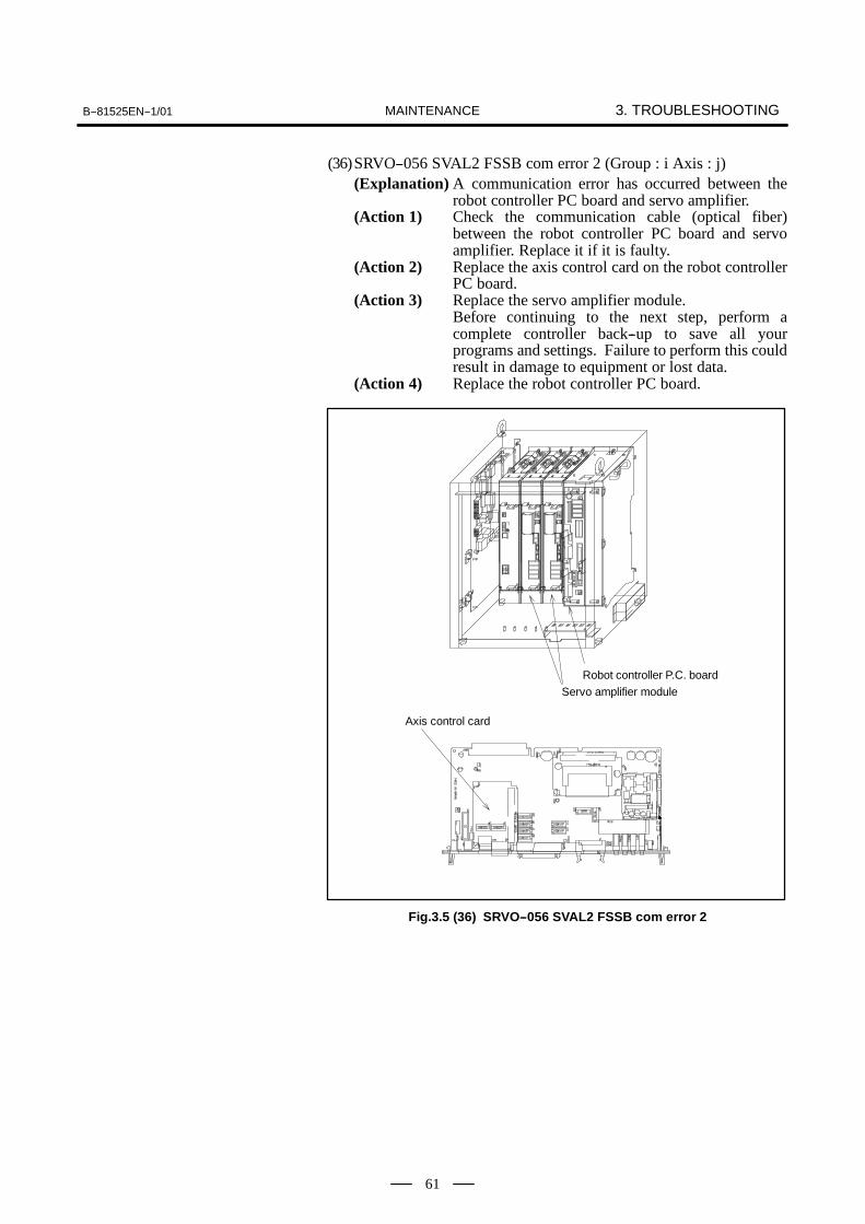
(36)SRVO--056 SVAL2 FSSB com error 2 (Group : i Axis : j)(Explanation) A communication error has occurred between the
robot controller PC board and servo amplifier.(Action 1) Check the communication cable (optical fiber)
between the robot controller PC board and servoamplifier. Replace it if it is faulty.
(Action 2) Replace the axis control card on the robot controllerPC board.
(Action 3) Replace the servo amplifier module.Before continuing to the next step, perform acomplete controller back--up to save all yourprograms and settings. Failure to perform this couldresult in damage to equipment or lost data.
(Action 4) Replace the robot controller PC board.
Robot controller P.C. boardServo amplifier module
Axis control card
Fig.3.5 (36) SRVO--056 SVAL2 FSSB com error 2

3. TROUBLESHOOTING B--81525EN--1/01MAINTENANCE
62
(37)SRVO--057 SVAL2 FSSB disconnect (Group : i Axis : j)(Explanation) Communication was interrupted between the robot
controller PC board and servo amplifier.(Action 1) Check whether fuse FU1 in the power supply module
unit has blown.(Action 2) Check whether fuse FU1 in the servo amplifier
module has blown.(Action 3) Check the communication cable (optical fiber)
between the robot controller PC board and servoamplifier. Replace it if it is faulty.
(Action 4) Replace the axis control card on the robot controllerPC board.
(Action 5) Replace the power supply module and the servoamplifier module.Before continuing to the next step, perform acomplete controller back--up to save all yourprograms and settings. Failure to perform this couldresult in damage to equipment or lost data.
(Action 6) Replace the robot controller PC board.(Action 7) Check the RMP cable of robot connection cable.
(+5V ground fault)
Robot controller P.C. boardServo amplifier module
Power supply moduleAxis control card
Fig.3.5 (37) SRVO--057 SVAL2 FSSB disconnect

B--81525EN--1/01 3. TROUBLESHOOTINGMAINTENANCE
63
(38)SRVO--058 SVAL2 FSSB init error (Group : i Axis : j)(Explanation) Communication was interrupted between the robot
controller PC board and servo amplifier module.(Action 1) Check whether fuse FU1 in the power supply module
have blown.If they have blown, see Section 3.6, “Troubleshootingfor Blown Fuse.”
(Action 2) Check whether seven segment LEDs on the servoamplifier module are on.If they are on, perform “Action 4” and all actions thatfollow it. If they are not on, perform “Action 3” andall actions that follow it.
(Action 3) Check whether connector CX1 on the power supplymodule is securely connected.
(Action 4) Check the communication cable (optical fiber)between the robot controller PC board and servoamplifier module. Replace it if it is faulty.
(Action 5) Replace the axis control card on the robot controllerPC board.
(Action 6) If the seven--segment LED on the servo amplifiermodule is glowing, replace the servo amplifiermodule. If the seven--segment LED on the servoamplifier module is not glowing, replace the powersupply module.Before continuing to the next step, perform acomplete controller back--up to save all yourprograms and settings. Failure to perform this couldresult in damage to equipment or lost data.
(Action 7) Replace the robot controller PC board.
Robot controller P.C. boardServo amplifier module
Power supply moduleAxis control card
Fig.3.5 (38) SRVO--058 SVAL2 FSSB init error
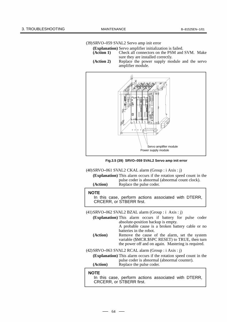
3. TROUBLESHOOTING B--81525EN--1/01MAINTENANCE
64
(39)SRVO--059 SVAL2 Servo amp init error(Explanation) Servo amplifier initialization is failed.(Action 1) Check all connectors on the PSM and SVM. Make
sure they are installed correctly.(Action 2) Replace the power supply module and the servo
amplifier module.
Servo amplifier modulePower supply module
Fig.3.5 (39) SRVO--059 SVAL2 Servo amp init error
(40)SRVO--061 SVAL2 CKAL alarm (Group : i Axis : j)(Explanation) This alarm occurs if the rotation speed count in the
pulse coder is abnormal (abnormal count clock).(Action) Replace the pulse coder.
NOTEIn this case, perform actions associated with DTERR,CRCERR, or STBERR first.
(41)SRVO--062 SVAL2 BZAL alarm (Group : i Axis : j)(Explanation) This alarm occurs if battery for pulse coder
absolute-position backup is empty.A probable cause is a broken battery cable or nobatteries in the robot.
(Action) Remove the cause of the alarm, set the systemvariable ($MCR.$SPC RESET) to TRUE, then turnthe power off and on again. Mastering is required.
(42)SRVO--063 SVAL2 RCAL alarm (Group : i Axis : j)(Explanation) This alarm occurs if the rotation speed count in the
pulse coder is abnormal (abnormal counter).(Action) Replace the pulse coder.
NOTEIn this case, perform actions associated with DTERR,CRCERR, or STBERR first.

B--81525EN--1/01 3. TROUBLESHOOTINGMAINTENANCE
65
(43)SRVO--064 SVAL2 PHAL alarm (Group : i Axis : j)(Explanation) This alarm occurs if the phase of the pulses generated
in the pulse coder is abnormal.(Action) Replace the pulse coder.
NOTEThis alarm might accompany the DTERR, CRCERR, orSTBERR alarm. In this case, however, there is no actualcondition for this alarm.
(44)SRVO--065 WARN BLAL alarm (Group : i Axis : j)(Explanation) The battery voltage for the pulse coder is lower than
the rating.(Action) Replace the battery.
(If this alarm occurs, turn on the AC power andreplace the battery as soon as possible. A delay inbattery replacement may result in the BZAL alarmbeing detected. In this case, the position data will belost. Once the position data is lost, mastering willbecome necessary.
(45)SRVO--066 SVAL2 CSAL alarm (Group : i Axis : j)(Explanation) The ROM in the pulse coder is abnormal.(Action) Replace the pulse coder.
NOTEThis alarm might accompany the DTERR, CRCERR, orSTBERR alarm. In this case, however, there is no actualcondition for this alarm.
(46)SRVO--067 SVAL2 OHAL2 alarm (Group : i Axis : j)(Explanation) The temperature inside the pulse coder or motor is
abnormally high, and the built--in thermostat hasoperated.
(Action 1) Check the operating conditions for the robot and relaxthe service conditions.
(Action 2) When power is supplied to the motor after it hasbecome sufficiently cool, if the alarm still occurs,replace the motor.
(47)SRVO--068 SVAL2 DTERR alarm (Group : i Axis : j)(Explanation) The serial pulse coder does not return serial data in
response to a request signal.--See actions on SRVO--070
(48)SRVO--069 SVAL2 CRCERR alarm (Group : i Axis : j)(Explanation) The serial data has disturbed during communication.
--See actions on SRVO--070

3. TROUBLESHOOTING B--81525EN--1/01MAINTENANCE
66
(49)SRVO--070 SVAL2 STBERR alarm (Group : i Axis : j)(Explanation) The start and stop bits of the serial data are abnormal.(Action 1) Make sure that the JF1 to JF3 connector of servo
amplifire module is connected tightly.(Action 2) Check that the shielding of the robot interconnection
cable (for the pulse coder) and the peripheral equipmentcable is connected securely to the grounding plate.
(Action 3) Check that each unit is grounded securely.(Action 4) Replace the servo amplifier module.(Action 5) Replace the pulse coder.(Action 6) Replace the robot interconnection cable (RMP).
Servo amplifier module
Fig.3.5 (49) SRVO--070 SVAL2 STBERR alarm
(50)SRVO--071 SVAL2 SPHAL alarm (Group : i Axis : j)(Explanation) The feedback speed is abnormally high.(Action 1) If this alarm occurs together with the PHAL alarm
(No. 064), this alarm does not correspond to the majorcause of the failure.
(Action 2) Replace the pulse coder.
(51)SRVO--072 SVAL2 PMAL alarm (Group : i Axis : j)(Explanation) It is likely that the pulse coder is abnormal.(Action) Replace the pulse coder and remaster the robot.
(52)SRVO--073 SVAL2 CMAL alarm (Group : i Axis : j)(Explanation) It is likely that the pulse coder is abnormal or thepulse
coder has malfunctioned due to noise.(Action) Master the robot and enhance the shielding.
(53)SRVO--074 SVAL2 LDAL alarm (Group : i Axis : j)(Explanation) The LED in the pulse coder is broken.(Action) Replace the pulse coder, and remaster the robot.
(54)SRVO--075 WARN Pulse not established (Group : i Axis : j)(Explanation) The absolute position of the pulse coder cannot be
established.(Action) Reset the alarm, and jog the axis on which the alarm
has occurred until the same alarm will not occuragain. (Jog one motor revolution)

B--81525EN--1/01 3. TROUBLESHOOTINGMAINTENANCE
67
(55)SRVO--076 SVAL1 Tip Stick Detection (Group : i Axis : j)(Explanation) An excessive disturbance was assumed in servo
software at the start of operation. (An abnormal loadwas detected. The cause may be welding.)
(Action 1) Check whether the robot comes into collision withforeign matter. If a collision occurs, reset the system,then switch it to the jog feed mode to avoid thecollision.
(Action 2) Check whether the load settings are valid.(Action 3) Check whether the load weight is within the rated
range. If the weight exceeds the upper limit, decreaseit to the limit.(Use of the robot with a load exceeding the limitapplied may abnormally increase the assumeddisturbance, resulting in this alarm.)
(Action 4) Check each inter--phase voltage of the three--phaseinput (200 VAC) to the power supply module. If thevoltage is 170 VAC or lower, check the input powersupply voltage.
(Action 5) Replace the power supply module and the servoamplifier module.
Servo amplifier modulePower supply module
Fig.3.5 (60) SRVO--076 SVAL1 Tip Stick Detection
(56)SRVO--081 WARN EROFL alarm (Track enc : i)(Explanation) The pulse counter for line tracking has overflowed.
(57)SRVO--082 WARN DAL alarm (Track ebc : i)(Explanation) The line tracking pulse coder has not been connected.(Action 1) Check the pulse coder connection cable, and replace
it if necessary.(Action 2) Replace the pulse coder.
(58)SRVO--083 WARN CKAL alarm (Track ebc : i)(Explanation) This alarm occurs if the rotation speed count in the
pulse coder is abnormal (abnormal count clock).(Action) See the description about the SRVO--061 CKAL
alarm.

3. TROUBLESHOOTING B--81525EN--1/01MAINTENANCE
68
(59)SRVO--084 WARN BZAL alarm (Track enc : i)(Explanation) This alarm occurs if the backup battery for the absolute
position of the pulse coder has not been connected. Seethe description about the BZAL alarm (SRVO--062).
(60)SRVO--085 WARN RCAL alarm (Track ebc : i)(Explanation) This alarm occurs if the rotation speed count in the
pulse coder is abnormal (abnormal counter).(Action) See the description about the SRVO--063 RCAL
alarm.(61)SRVO--086 WARN PHAL alarm (Track enc : i)
(Explanation) This alarm occurs if the phase of pulses generated inthe pulse coder is abnormal. See the descriptionabout the PHAL alarm (SRVO--064).
(62)SRVO--087 WARN BLAL alarm (Track enc : i)(Explanation) This alarm occurs if the voltage of the backup battery
for the absolute position of the pulse coder is low. Seethe description about the BLAL alarm (SRVO--065).
(63)SRVO--088 WARN CSAL alarm (Track ebc : i)(Explanation) The ROM in the pulse coder is abnormal.(Action) See the description about the SRVO--066 CSAL
alarm.(64)SRVO--089 WARN OHAL2 alarm (Track enc : i)
(Explanation) The motor has overheated. See the description aboutthe OHAL2 alarm (SRVO--067).
(65)SRVO--090 WARN DTERR alarm (Track enc : i)(Explanation) Communication between the pulse coder and line
tracking interface board is abnormal. See thedescription about the DTERR alarm (SRVO--068).
(66)SRVO--091 WARN CRCERR alarm (Track enc : i)(Explanation) Communication between the pulse coder and line
tracking interface board is abnormal. See thedescription about the CRCERR alarm (SRVO--069).
(67)SRVO--092 WARN STBERR alarm (Track enc : i)(Explanation) Communication between the pulse coder and line
tracking interface board is abnormal. See thedescription about the STBERR alarm (SRVO--070).
(68)SRVO--093 WARN SPMAL alarm (Track enc : i)(Explanation) This alarm occurs if the current position data from the
pulse coder is higher than the previous position data.See the description about the SPHAL alarm(SRVO--071).
(69)SRVO--094 WARN PMAL alarm (Track enc : i)(Explanation) It is likely that the pulse coder is abnormal. See the
description about the PMAL alarm (SRVO--072).(70)SRVO--095 WARN CMAL alarm (Track enc : i)
(Explanation) It is likely that the pulse coder is abnormal or thepulsecoder has malfunctioned due to noise. See thedescription about the CMAL alarm (SRVO--073).
(71)SRVO--096 WARN LDAL alarm (Track enc : i)(Explanation) The LED in the pulse coder is broken. See the
description about the LDAL alarm (SRVO--074).

B--81525EN--1/01 3. TROUBLESHOOTINGMAINTENANCE
69
(72)SRVO--097 WARN Pulse not established (enc : i)(Explanation) The absolute position of the pulse coder cannot be
established. See the description about (SRVO--075).Pulse not established.
(73)SRVO--131 SVAL1 LVAL (PSM) alarm (Group : i Axis : j)(Explanation) The control power supply voltage (for example, +5
V) on the power supply module is abnormally low.The LED indication on the power supply module is“6” (LVAL).
(Action 1) Replace the power supply module.
Power supply module
Fig.3.5 (73) SRVO--131 SVAL1 LVAL(PSM) alarm
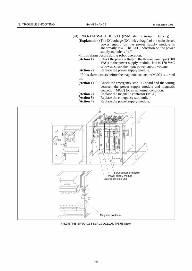
3. TROUBLESHOOTING B--81525EN--1/01MAINTENANCE
70
(74)SRVO--134 SVAL1 DCLVAL (PSM) alarm (Group : i Axis : j)(Explanation) The DC voltage (DC link voltage) of the main circuit
power supply on the power supply module isabnormally low. The LED indication on the powersupply module is “4.”
--If this alarm occurs during robot operation:(Action 1) Check the phase voltage of the three--phase input (200
VAC) to the power supply module. If it is 170 VACor lower, check the input power supply voltage.
(Action 2) Replace the power supply module.--If this alarm occurs before the magnetic contactor (MCC) is turnedon:(Action 1) Check the emergency stop PC board and the wiring
between the power supply module and magneticcontactor (MCC) for an abnormal condition.
(Action 2) Replace the magnetic contactor (MCC).(Action 3) Replace the emergency stop unit.(Action 4) Replace the power supply module.
Emergency stop unit
Servo amplifier modulePower supply module
Magnetic contactor
Fig.3.5 (74) SRVO--134 SVAL1 DCLVAL (PSM) alarm
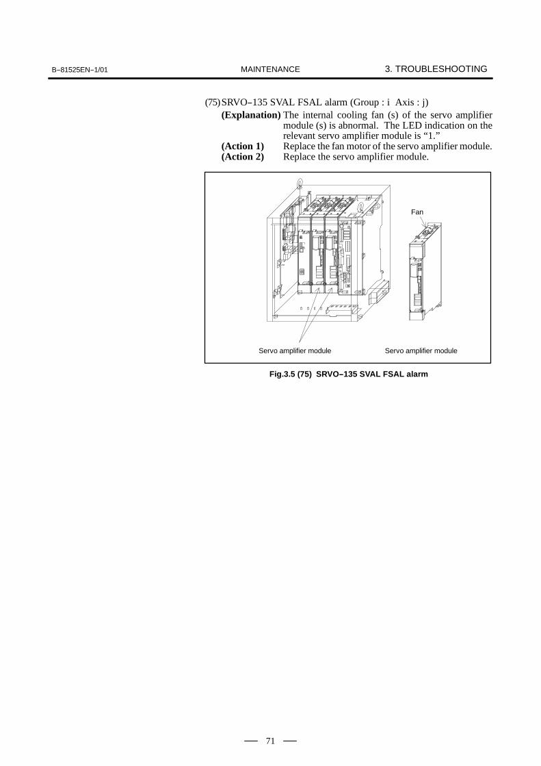
B--81525EN--1/01 3. TROUBLESHOOTINGMAINTENANCE
71
(75)SRVO--135 SVAL FSAL alarm (Group : i Axis : j)(Explanation) The internal cooling fan (s) of the servo amplifier
module (s) is abnormal. The LED indication on therelevant servo amplifier module is “1.”
(Action 1) Replace the fan motor of the servo amplifier module.(Action 2) Replace the servo amplifier module.
Servo amplifier module Servo amplifier module
Fan
Fig.3.5 (75) SRVO--135 SVAL FSAL alarm

3. TROUBLESHOOTING B--81525EN--1/01MAINTENANCE
72
(76)SRVO--136 SVAL1 DCLVAL alarm (Group : i Axis : j)(Explanation) The servo the DC current of amplifier (DC link
voltage) of the main power supply is abnormally low.The LED indication on the power supply modulebecomes “4”, and the LED indication on the servoamplifier module becomes “5”.
--This alarm occured in the robot operation.(Action 1) Check the phase voltage of the three--phase input
power (200 VAC) to the power supply module. If itis 170 VAC or lower, check the line voltage.
(Action 2) Replace the power supply module and the servoamplifier module.
--If this alarm occurs before the magnetic contactor is turned on:(Action 1) Check the emergency stop PC board and the wiring
between the power supply module and electromagneticcontactor (MCC) for an abnormal condition.
(Action 2) Replace the magnetic contactor.(Action 3) Replace the E--stop unit.(Action 4) Replace the power supply module.
Robot controller P.C. boardServo amplifier module
Power supply moduleMagnetic contactor
Fig.3.5 (76) SRVO--136 SVAL1 DCLVAL alarm

B--81525EN--1/01 3. TROUBLESHOOTINGMAINTENANCE
73
(77)SRVO--156 SVAL1 IPMAL alarm (Group : i Axis : j)(Explanation) Abnormally high current flowed through the main
circuit of the servo amplifier.The LED indications on the servo amplifier modulesare “8.”, “9.”, and “A.”.
(Action 1) Detach the motor power lines from the connectorsCZ2 of the servo amplifier modules, then turn on thepower. If this operation causes the error to recur,replace the servo amplifier module.
(Action 2) Detach the motor power lines from the connectorsCZ2 of the servo amplifier modules, then check theinsulation between GND and each of the motor powerlines U, V, and W individually. If a short--circuit isfound, the motor, robot interconnection cable, orintra--robot cable may be faulty. Examine each ofthem for any problem.
(Action 3) Detach the motor power lines from the connectorsCZ2 of the servo amplifier modules, then measure theresistance between the motor power lines U and V, Vand W, and W and U, using an ohmmeter with a verylow resistance range. If the three resistances aredifferent, the motor, robot connection cable, orintra--robot cable may be faulty. Examine each ofthem for any problem.Before taking (Action 4), make a backup copy of allthe programs and settings of the control unit.
(Action 4) Replace the robot controller PC board.
Robot controller P.C. boardServo amplifier module
Fig.3.5 (77) SRVO--156 SVAL1 IPMAL alarm

3. TROUBLESHOOTING B--81525EN--1/01MAINTENANCE
74
(78)SRVO--157 SVAL1 CHGAL alarm (Group : i Axis : j)(Explanation) The capacitor for the DC link voltage of the servo
amplifier module was not charged within thespecified time.
(Action 1) A short circuit may occur in the DC link voltage.Check the connection.
(Action 2) Replace the servo amplifier module.(Action 3) Replace the power supply module.
Servo amplifier modulePower supply module
Fig.3.5 (78) SRVO--157 SVAL1 CHGAL alarm

B--81525EN--1/01 3. TROUBLESHOOTINGMAINTENANCE
75
(79)SRVO--201 SVAL1 Panel E--stop or SVEMG abnormal(Explanation) The EMERGENCY STOP button on the operator
panel was pressed, but the EMERGENCY STOP linewas not disconnected.
(Action 1) Check the EMERGENCY STOP button on theoperator panel, and replace it if necessary.
(Action 2) Check whether fuse FUS3 on the emergency stop PCboard is blown. Replace if it is blown.
(Action 3) Check whether +24 V is connected to EMGIN2 on theterminal block TBEB5 of the emergency stop PCboard by mistake. Correct any wrong wiring.
(Action 4) Replace the emergency stop unit.(Action 5) Replace the power supply module.
NOTEThis alarm might occur if the EMERGENCY STOP buttonis pressed slowly.
Power supply module
emergency stop button
Emergency stop unit
Fig.3.5 (79) SRVO--201 SVAL1 Panel E--stop or SVEMG abnormal

3. TROUBLESHOOTING B--81525EN--1/01MAINTENANCE
76
(80)SRVO--202 SVAL1 TP E--stop or SVEMG abnormal(Explanation) The EMERGENCY STOP button on the operator
panel was pressed, but the EMERGENCY STOP linewas not disconnected.
(Action 1) Check the teach pendant connection cable.(Action 2) Replace the teach pendant.(Action 3) Check whether +24 V is incorrectly connected to
FENCE2 on the terminal block TBEB5 of theemergency stop PC board. If it is incorrectlyconnected, connect it again.
(Action 4) Replace the emergency stop unit.(Action 5) Replace the power supply module.
NOTEThis alarm might occur if the EMERGENCY STOP buttonis pressed slowly.
Power supply moduleEmergency stop unit
Teach pendant
Teach pendant cable
Emergencystop button
Emergency stop P.C. board
FENCE2 terminal
Fig.3.5 (80) SRVO--202 SVAL1 TP E--stop or SVEMG abnormal
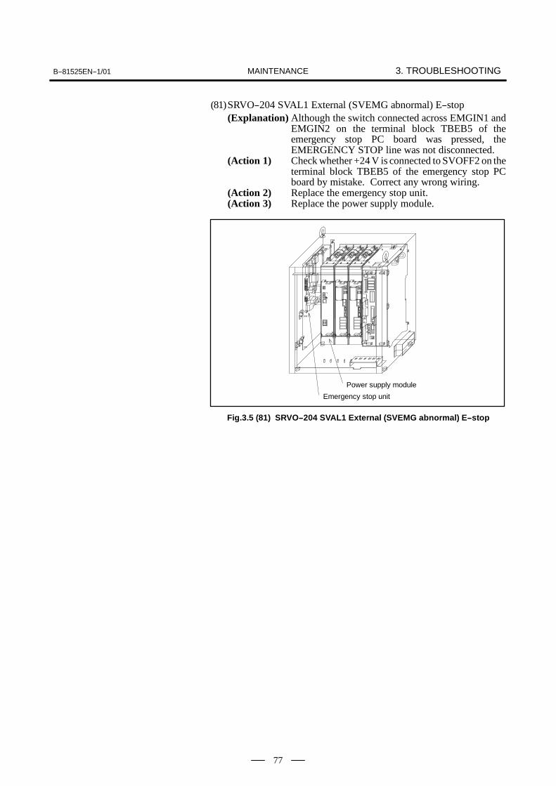
B--81525EN--1/01 3. TROUBLESHOOTINGMAINTENANCE
77
(81)SRVO--204 SVAL1 External (SVEMG abnormal) E--stop(Explanation) Although the switch connected across EMGIN1 and
EMGIN2 on the terminal block TBEB5 of theemergency stop PC board was pressed, theEMERGENCY STOP line was not disconnected.
(Action 1) Check whether +24 V is connected to SVOFF2 on theterminal block TBEB5 of the emergency stop PCboard by mistake. Correct any wrong wiring.
(Action 2) Replace the emergency stop unit.(Action 3) Replace the power supply module.
Power supply module
Emergency stop unit
Fig.3.5 (81) SRVO--204 SVAL1 External (SVEMG abnormal) E--stop

3. TROUBLESHOOTING B--81525EN--1/01MAINTENANCE
78
(82)SRVO--205 SVAL1 Fence open (SVEMG abnormal)(Explanation) The EMERGENCY STOP line was not disconnected
even though the switch connected between FENCE1and FENCE2 on the terminal block TBEB5 of theemergency stop PC board was open.
(Action 1) Check whether +24 V is connected to EMGIN2 on theterminal block TBEB5 of the emergency stop PCboard by mistake. Correct any incorrect wiring.
(Action 2) Replace the emergency stop unit.(Action 3) Replace the power supply module.
Power supply module
Emergency stop unit
Fig.3.5 (82) SRVO--205 SVAL1 Fence open (SVEMG abnormal)
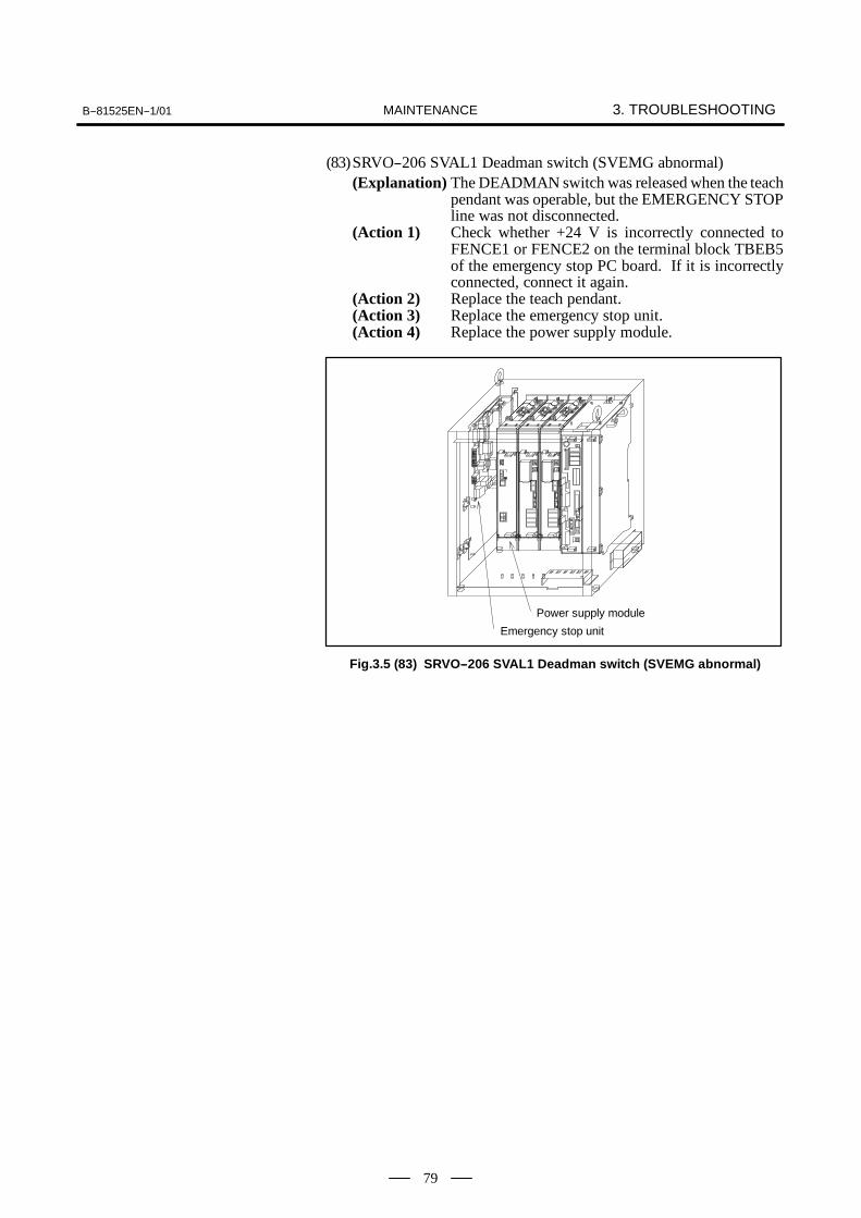
B--81525EN--1/01 3. TROUBLESHOOTINGMAINTENANCE
79
(83)SRVO--206 SVAL1 Deadman switch (SVEMG abnormal)(Explanation) The DEADMAN switch was released when the teach
pendant was operable, but the EMERGENCY STOPline was not disconnected.
(Action 1) Check whether +24 V is incorrectly connected toFENCE1 or FENCE2 on the terminal block TBEB5of the emergency stop PC board. If it is incorrectlyconnected, connect it again.
(Action 2) Replace the teach pendant.(Action 3) Replace the emergency stop unit.(Action 4) Replace the power supply module.
Power supply module
Emergency stop unit
Fig.3.5 (83) SRVO--206 SVAL1 Deadman switch (SVEMG abnormal)
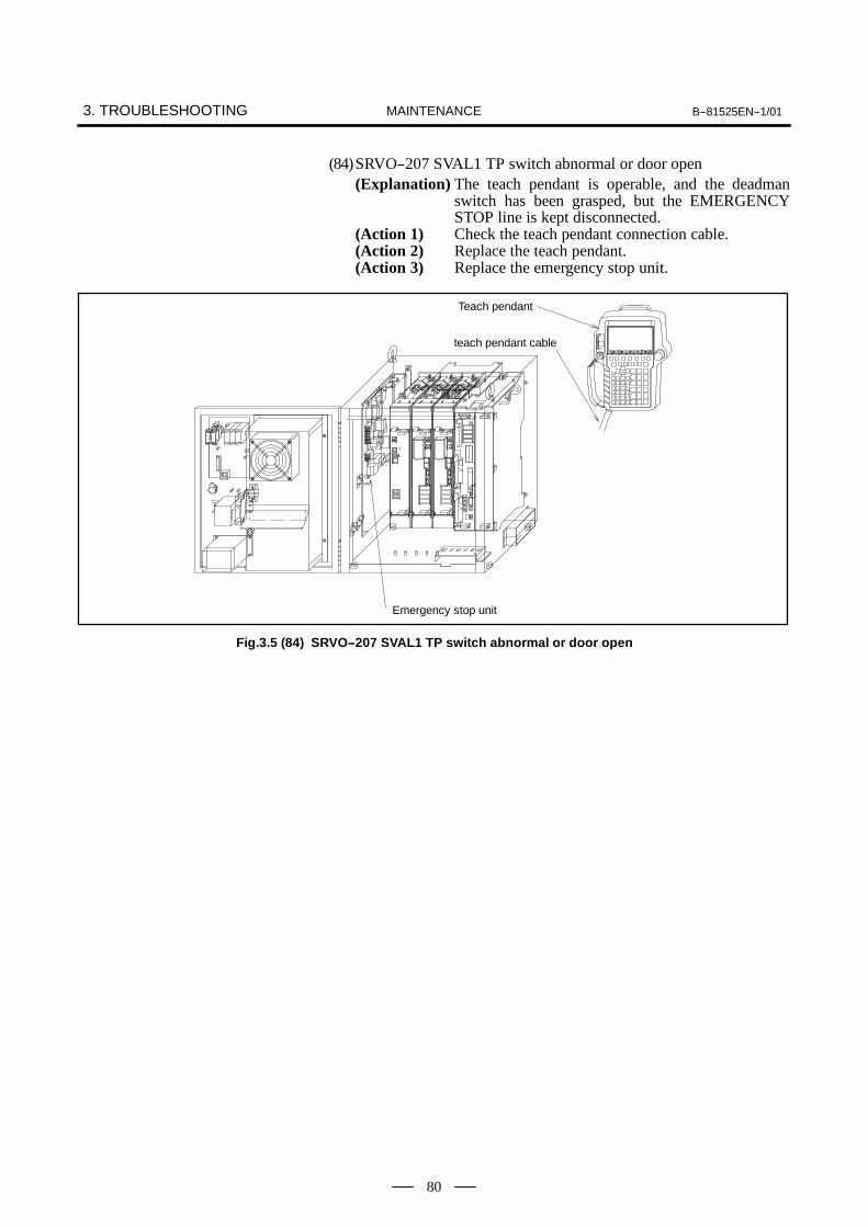
3. TROUBLESHOOTING B--81525EN--1/01MAINTENANCE
80
(84)SRVO--207 SVAL1 TP switch abnormal or door open(Explanation) The teach pendant is operable, and the deadman
switch has been grasped, but the EMERGENCYSTOP line is kept disconnected.
(Action 1) Check the teach pendant connection cable.(Action 2) Replace the teach pendant.(Action 3) Replace the emergency stop unit.
Emergency stop unit
Teach pendant
teach pendant cable
Fig.3.5 (84) SRVO--207 SVAL1 TP switch abnormal or door open
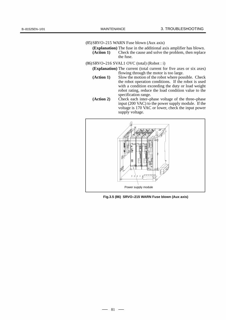
B--81525EN--1/01 3. TROUBLESHOOTINGMAINTENANCE
81
(85)SRVO--215 WARN Fuse blown (Aux axis)(Explanation) The fuse in the additional axis amplifier has blown.(Action 1) Check the cause and solve the problem, then replace
the fuse.
(86)SRVO--216 SVAL1 OVC (total) (Robot : i)(Explanation) The current (total current for five axes or six axes)
flowing through the motor is too large.(Action 1) Slow the motion of the robot where possible. Check
the robot operation conditions. If the robot is usedwith a condition exceeding the duty or load weightrobot rating, reduce the load condition value to thespecification range.
(Action 2) Check each inter--phase voltage of the three--phaseinput (200 VAC) to the power supply module. If thevoltage is 170 VAC or lower, check the input powersupply voltage.
Power supply module
Fig.3.5 (86) SRVO--215 WARN Fuse blown (Aux axis)

3. TROUBLESHOOTING B--81525EN--1/01MAINTENANCE
82
(87)SRVO--221 SVAL1 Lack of DSP (Group : i Axis : j)(Explanation) A controlled axis card corresponding to the set
number of axes is not mounted.(Action 1) Check whether the set number of axes is valid. If the
number is invalid, set the correct number.(Action 2) Replace the controlled axis card with a card
corresponding to the set number of axes.(Example)When six axes are set, a controlled axis card for sixor eight axes is available. For how to replace thecontrolled axis card, see II MAINTENANCE,Section 7.2 in this manual.
Robot controller P.C. boardServo amplifier module
Power supply moduleAxis control card
Fig.3.5 (87) SRVO--221 SVAL1 Lack of DSP (Group : i Axis : j)

B--81525EN--1/01 3. TROUBLESHOOTINGMAINTENANCE
83
(88)SRVO--222 SVAL1 Lack of Amp (Amp : i)(Explanation) The FSSB has no SVM.(Action 1) Check that the optical cable is securely connected to
the servo amplifier module.(Action 2) Replace the optical cable.(Action 3) Check whether power is properly supplied to the
servo amplifier module.
Servo amplifier module
Fig.3.5 (88) SRVO--222 SVAL1 Lack of Amp (Amp : i)

3. TROUBLESHOOTING B--81525EN--1/01MAINTENANCE
84
(89)SRVO--233 SVAL1 TP disabled in T1, T2/Door open(Explanation) The teach pendant is disabled when the mode switch
is in the T1 mode or T2 mode position.(Action 1) During teaching operation, set the enable switch of
the teach pendant to Enable. Otherwise, set the modeswitch to AUTO mode.
(Action 2) Replace the emergency stop unit.(Action 3) Replace the teach pendant.(Action 4) The mode switch may be faulty. Replace the operator
panel.
Emergency stop unit
Teach pendant
Emergency stop P.C. board
FUS3
Mode switch
Fig.3.5 (89) SRVO--233 SVAL1 TP disabled in T1, T2/Door open

B--81525EN--1/01 3. TROUBLESHOOTINGMAINTENANCE
85
(90)SRVO--264 SVAL1 “E.STOP circuit abnormal 1”(Explanation) An error occurred in the emergency stop circuit.(Action 1) Check whether the CRR78 connectors on the
E--STOP unit and the CX3 connector of the powersupply module are connected securely.
(Action 2) Replace the emergency stop unit.(Action 3) Replace the power supply module.
Power supply module
Emergency stop unit
Fig.3.5 (90) SRVO--264 SVAL1 “E.STOP circuit abnormal 1”

3. TROUBLESHOOTING B--81525EN--1/01MAINTENANCE
86
(91)SRVO--265 SVAL1 E.STOP circuit abnormal 2(Explanation) When the servo amplifier is excited, the monitor
contact of the magnetic contactor (MCC) becomesfaulty.
(Action 1) Replace the magnetic contactor (MCC).(Action 2) Replace the emergency stop unit.(Action 3) Replace the power supply module.
Power supply module
Emergency stop unit
Magnetic contactor
Fig.3.5 (91) SRVO--265 SVAL1 E.STOP circuit abnormal 2

B--81525EN--1/01 3. TROUBLESHOOTINGMAINTENANCE
87
(92)SRVO--290 SVAL1 DClink HC alarm (Group : i Axis : j)(Explanation) The DC link current in the servo amplifier module(s)
is abnormal. The LED indication on the relevantservo amplifier module is “8.”
(Action 1) Detach the motor power lines from connector CZ2 ofthe servo amplifier module, then turn the power on.If this alarm persists, replace the servo amplifiermodule.
(Action 2) Detach the motor power lines from connector CZ2 ofthe servo amplifier module, then check the insulationbetween GND and each of U, V, and W of the motorpower lines. If a short circuit is detected, the motor,robot connection cable, or internal robot cable may bedefective. Check them for an abnormal condition.
(Action 3) Detach the motor power lines from connector CZ2 ofthe servo amplifier module, then use a high--precisionohmmeter to measure U--V, V--W, and W--Uresistances of the motor power lines. If the threeresistances differ, the motor, robot connection cable,or internal robot cable may be defective. Check themfor an abnormal condition.Before proceeding with (Action 4), back up allprograms and settings for the control unit.
(Action 4) Replace the robot control PC board.
Robot controller P.C. boardServo amplifier module
Fig.3.5 (92) SRVO--290 SVAL1 DClink HC alarm
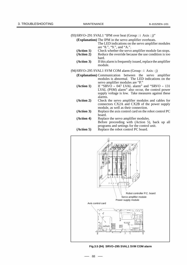
3. TROUBLESHOOTING B--81525EN--1/01MAINTENANCE
88
(93)SRVO--291 SVAL1 “IPM over heat (Group : i Axis : j)”(Explanation) The IPM in the servo amplifier overheats.
The LED indications on the servo amplifier modulesare “8.”, “9.”, and “A.”.
(Action 1) Check whether the servo amplifier module fan stops.(Action 2) Reduce the override because the use condition is too
hard.(Action 3) If this alarm is frequently issued, replace the amplifier
module.
(94)SRVO--295 SVAL1 SVM COM alarm (Group : i Axis : j)(Explanation) Communication between the servo amplifier
modules is abnormal. The LED indications on theservo amplifier modules are “P.”
(Action 1) If “SRVO -- 047 LVAL alarm” and “SRVO -- 131LVAL (PSM) alarm” also occur, the control powersupply voltage is low. Take measures against thesealarms.
(Action 2) Check the servo amplifier modules and cables forconnectors CX2A and CX2B of the power supplymodule, as well as their connection.
(Action 3) Replace the axis control card on the robot control PCboard.
(Action 4) Replace the servo amplifier modules.Before proceeding with (Action 5), back up allprograms and settings for the control unit.
(Action 5) Replace the robot control PC board.
Robot controller P.C. boardServo amplifier module
Power supply moduleAxis control card
Fig.3.5 (94) SRVO--295 SVAL1 SVM COM alarm

B--81525EN--1/01 3. TROUBLESHOOTINGMAINTENANCE
89
(95)SRVO--296 SVAL1 DCAL alarm (Group : i Axis : j)(Explanation) The regenerative discharge energy is too high to be
dissipated as heat. (To move the robot, the servoamplifier supplies energy to the robot. When goingdown, the robot moves along the vertical axis as thepotential energy reduces. If a reduction in thepotential energy is larger than the amount ofacceleration energy, the servo amplifier receivesenergy from the motor. This also occurs atdeceleration even when no gravity is applied. Theenergy that the servo amplifier receives from themotor is called regenerative energy. The servoamplifier dissipates this energy as heat. If the amountof the regenerative energy dissipated as heat issmaller than was received, the remainder is stored inthe servo amplifier, causing this alarm.) The LEDindication on the power supply module is “8”(DCAL: regenerative energy adder detection).
(Action 1) This alarm may occur if the robot is subjected tofrequent acceleration/deceleration or if the verticalaxis generates a large amount of regenerative energy.In this case, relax the service conditions.
(Action 2) Replace the power supply module.
Power supply module
Fig.3.5 (95) SRVO--296 SVAL1 DCAL alarm

3. TROUBLESHOOTING B--81525EN--1/01MAINTENANCE
90
(96)SRVO--297 SVAL1 DCLVAL alarm (Group : i Axis : j)(Explanation) An open--phase condition has occurred in the input
power supply to the main circuit on the power supplymodule. The LED indications on the power supplymodule is “E.”
(Action 1) Check the phase voltage of the three--phase input (200VAC) to the power supply module. If an open--phasecondition is detected, check the input power supply.
(Action 2) Replace the power supply module.
Power supply module
Fig.3.5 (96) SRVO--297 SVAL1 DCLVAL alarm
(97)SRVO--300 SVAL1 Hand broken/HBK disabledSRVO--302 SVAL1 Set Hand broken to ENABLE(Explanation) Although HBK was disabled, the HBK signal was
input.(Action 1) Press RESET on the teach pendant to release the
alarm.(Action 2) Check whether the hand broken signal is connected to
the robot. When the hand broken signal circuit isconnected, enable hand broken. (See IICONNECTION, Section 3.8 in this manual.)
Robot controller P.C. board
Fig.3.5 (97) SRVO--300 SVAL1 Hand broken/HBK disabledSRVO--302 SVAL1 Set Hand broken to ENABLE

B--81525EN--1/01 3. TROUBLESHOOTINGMAINTENANCE
91
(98)SRVO--322 SVOFF input/E.STOP(Explanation) SVOFF1 and SVOFF2 on the terminal block TBEB5
of the emergency stop PC board are notshort--circuited. If a servo off input signal line isconnected across SVOFF1 and SVOFF2, the servooff input signal contact is open.
(Action 1) If the servo off input signal line is connected, close theservo off input signal contact.
(Action 2) Examine the cables and switches connected toSVOFF1 and SVOFF2.
(Action 3) If this signal is not used, short--circuit SVOFF1 andSVOFF2.
NOTEIf the system uses the servo off input signal, avoidshort--circuiting and disabling this signal. It is verydangerous. If the system has to be operated with the signalshort--circuited temporarily, a corresponding safetyprovision must be taken.
(Action 4) Replace the emergency stop unit.Before taking (Action 5), make a backup copy of allthe programs and settings of the control unit.
(Action 5) Replace the robot controller PC board.
Emergency stop unitRobot controller P.C. board
Shortconnectionboard
Fig.3.5 (98) SRVO--322 SVOFF input/E.STOP

3. TROUBLESHOOTING B--81525EN--1/01MAINTENANCE
92
This section describes alarms that can occur when a fuse mounted on a PCboard or unit is blown and corresponding corrective actions.
(1) Fuses on the robot controller PC boardFUS1 : For generating power to the control circuitFUS2 : For protecting +24E output to peripheral device digital
input/output, end effector, ROT, and HBK
Name Problem caused by blown fuse Action
FUS1 The control power of the robot controller PC board is shut off.The teach pendant displays the initial screen.
1 Check the units (fans) and cables connected to the CP2 andCP3 connectors of the power supply unit to see if there is anyshort circuit.
2 Replace the DC/DC converter module.3 Replace the robot controller PC board.
FUS2 The teach pendant screen displays alarm information such asHand broken (SERVO -- 006) or Robot overtravel (SERVO --005).
1 Check that +24E used by the peripheral device is free from aground fault.
2 Examine the peripheral device connection cable.3 Check that +24E used by the end effector is free from a ground
fault.4 Examine the robot interconnection cable and intra--robot
cable.
FUS1 FUS2
3.6TROUBLESHOOTINGUSING FUSES

B--81525EN--1/01 3. TROUBLESHOOTINGMAINTENANCE
93
(2) Fuses on the emergency stop PC boardFUS3 : For monitoring the emergency stop circuitFUS4 : For controlling the emergency stop circuit and teach pendantFUS5 : For the brake circuit
Name Problem caused by blown fuse Action
FUS3 The teach pendant screen displays SVAL1 TP dis-abled in T1, T2/Door open (SERVO -- 233) and so forth.
Replace the emergency stop unit.
FUS4 The power supply to the teach pendant stops, thescreen display of the teach pendant disappears, andthe system enters the emergency stop state.
1 Examine the teach pendant cable for any problem.2 Examine the teach pendant for any problem.3 Check that the external emergency stop input and servo off input are
free from a ground fault and any other fault.
FUS5 Replace the emergency stop unit.The robot motor brake cannot be released, and alarminformation such as Large error in travel (SERVO --024), Large error at rest (SERVO -- 023), Positioningtime over (SERVO -- 036), or CLALM alarm (SERVO-- 050) is displayed.
1 Check that the robot interconnection cable (RMP) and intra--mechani-cal--unit cable are free from faults such as a ground fault and short--cir-cuit.
2 If an additional axis is used, check that the brake connection cable isfree from a ground fault, short--circuit, and any other fault.
3 If a brake power transformer is used, note that a faulty brake powertransformer can cause a too large current to flow. Replace the brakepower transformer.
4 Replace the emergency stop unit.
FUS3
FUS4
FUS5
Emergency stop P.C.board

3. TROUBLESHOOTING B--81525EN--1/01MAINTENANCE
94
(3) Fuse on the power supply module
FU1 : For protecting 200 VAC input to generate power to thecontrol circuit
Name Problem caused by blown fuse Action
FU1 ALL LEDs of the servo amplifiers go out.The teach pendant screen displays the FSSB disconnectionalarm or FSSB initialization alarm.
1 Replace the fuse (5 A) on the control PC board of the powersupply module.
2 Replace the power supply module.
FU1
Remove the face plate

B--81525EN--1/01 3. TROUBLESHOOTINGMAINTENANCE
95
(4) Fuse on the servo amplifier module
FU1 : For protecting +24 V input to generate power to the controlcircuit
Name Problem caused by blown fuse Action
FU1 ALL LEDs of the servo amplifier modules go out.The teach pendant screen displays the FSSB disconnectionalarm or FSSB initialization alarm.
1 Replace the fuse (3.2 A) on the control PC board of the servoamplifier module.
2 Replace the servo amplifier module.
FU1
Remove the control P.C. board
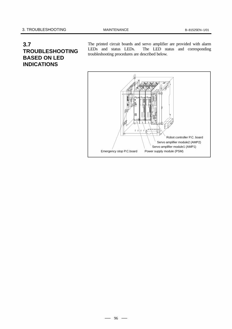
3. TROUBLESHOOTING B--81525EN--1/01MAINTENANCE
96
The printed circuit boards and servo amplifier are provided with alarmLEDs and status LEDs. The LED status and correspondingtroubleshooting procedures are described below.
Servo amplifier module1 (AMP1)Power supply module (PSM)
Servo amplifier module2 (AMP2)
Robot controller P.C. board
Emergency stop P.C.board
3.7TROUBLESHOOTINGBASED ON LEDINDICATIONS

B--81525EN--1/01 3. TROUBLESHOOTINGMAINTENANCE
97
(1) TROUBLESHOOTING USING THE LEDS ON THE robotcontroller PC boardTo troubleshoot an alarm that arises before the teach pendant is readyto display, check the status LEDs (green) on the robot controller PCboard at power--on.After power--on, the LEDs light as described in steps 1 to 18, in theorder described. If an alarm is detected, the step in which the alarmoccurred can be determined from which LEDs are lit.
Step LED Action to be taken
1: After power--on, all LEDs arelit.
[Action1] Replace the CPU card* [Action2] Replace the robot controller PC board.
2: Software operation start--up. [Action1] Replace the CPU card* [Action2] Replace the robot controller PC board.
3: The initialization of dram onthe CPU card is completed.
[Action1] Replace the CPU card* [Action2] Replace the robot controller PC board.
4: The initialization of SRAMand DPRAM is completed.
[Action1] Replace the CPU card* [Action2] Replace the robot controller PC board.* [Action3] Replace the FROM/SRAM module.
5: The initialization of the com-munication IC is completed.
[Action1] Replace the CPU card* [Action2] Replace the robot controller PC board.* [Action3] Replace the FROM/SRAM module.
6: The loading of the basic soft-ware is completed.
* [Action1] Replace the robot controller PC board.* [Action2] Replace the FROM/SRAM module.
7: Basic software start--up. * [Action1] Replace the robot controller PC board.* [Action2] Replace the FROM/SRAM module.
8: Start--up of communicationwith the teach pendant.
* [Action1] Replace the robot controller PC board.* [Action2] Replace the FROM/SRAM module.
9: The loading of optional soft-ware is completed.
* [Action1] Replace the robot controller PC board.
10:DI/DO initialization * [Action1] Replace the FROM/SRAM module.* [Action2] Replace the robot controller PC board.
11:The preparation of the SRAMmodule is completed.
[Action1] Replace the axis control card.* [Action2] Replace the robot controller PC board.
[Action3] Replace the servo amplifier.
* If the robot controller PC board or FROM/SRAM module is replaced, the contents of memory (parameters,specified data, etc.) will be lost. Before you replace the unit, therefore, make a backup copy of the data.

3. TROUBLESHOOTING B--81525EN--1/01MAINTENANCE
98
Step Action to be takenLED
12:Axis control card initialization [Action1] Replace the axis control card.* [Action2] Replace the robot controller PC board.
[Action3] Replace the servo amplifier.
13:Calibration is completed. [Action1] Replace the axis control card.* [Action2] Replace the robot controller PC board.
[Action3] Replace the servo amplifier.
14:Start--up of power applicationfor the servo system
* [Action1] Replace the robot controller PC board.
15:Program execution * [Action1] Replace the robot controller PC board.
16:DI/DO output start--up. * [Action1] Replace the robot controller PC board.
17: Initialization is terminated. Initialization has ended normally.
18:Normal status Status LEDs 1 and 2 blink when the system is operating normally.
* If the robot controller PC board or FROM/SRAM module is replaced, the contents of memory (parameters,specified data, etc.) will be lost. Before you replace the unit, therefore, make a backup copy of the data.
Axis control card FROM/SRAM module(under the CPU card)
CPU card

B--81525EN--1/01 3. TROUBLESHOOTINGMAINTENANCE
99
(2) TROUBLESHOOTING BY 7--SEGMENT LED INDICATOR
7--segment LEDindicator Description
[Description] A parity alarm condition has occurred in RAM on the CPU card installed on the robotcontroller PC board.
[Action1] Replace the CPU card.[Action2] Replace the robot controller PC board.
[Description] A parity alarm condition has occurred in RAM on the FROM/SRAM module installedon the robot controller PC board.
[Action1] Replace the FROM/SRAM module.[Action2] Replace the robot controller PC board.
“2”, “3”, and “4” are not displayed.
[Description] A servo alarm condition has occurred on the robot controller PC board.[Action1] Replace the axis control card.[Action2] Replace the robot controller PC board.
[Description] The SYSEMG alarm has occurred.[Action1] Replace the axis control card.[Action2] Replace the CPU card.[Action3] Replace the robot controller PC board.
[Description] The SYSFAIL alarm has occurred.[Action1] Replace the axis control card.[Action2] Replace the CPU card.[Action3] Replace the robot controller PC board.
* If the robot controller PC board or FROM/SRAM module is replaced, the contents of memory (parameters,specified data, etc.) will be lost. Before you replace the unit, therefore, make a backup copy of the data.

3. TROUBLESHOOTING B--81525EN--1/01MAINTENANCE
100
(3) Troubleshooting using a fuse alarm LED
LED indication Failure description and required measure
[Description] A fuse (FUS1 or FUS2) is blown.Cause of the blowing of FUS1 and corrective actions
[Action1] Check whether the device which is connected to the RS--232--C/RS--422 portand requires the power supply of +24 V is sound.
[Action2] Faulty DC/DC converter moduleReplace the DC/DC converter module.
[Action3] Short--circuited surge absorber PVS1The system can be operated temporarily without PVS1. However, obtain andmount a new one at the earliest possible time.
[Action4] Faulty robot controller PC boardReplace the robot controller PC board.
Cause of the blowing of FUS2 and corrective actions[Action1] Check that +24E used by the peripheral device is free from a ground fault.[Action2] Examine the peripheral device connection cable.[Action3] Check that +24E used by the end effector is free from a ground fault.[Action4] Examine the robot interconnection cable and intra--robot cable.

B--81525EN--1/01 3. TROUBLESHOOTINGMAINTENANCE
101
Troubleshooting using an LED on the emergency stop PC board
LED indication Problem and corrective action
[Description] The fuse (FUS3, FUS4, or FUS5) is blown.Cause of the blowing of FUS3 and corrective action
[Action] The emergency stop PC board is faulty. Replace the emergency stop unit.Cause of the blowing of FUS4 and corrective actions
[Action1] Check that the teach pendant cable is sound.[Action2] Check that the teach pendant is sound.[Action3] Check that the external emergency stop input and servo off input are free from
a ground fault and any other fault.[Action4] The emergency stop PC board is faulty. Replace the emergency stop unit.
Cause of the blowing of FUS5 and corrective actions[Action1] Check that the robot interconnection cable (RMP) and intra--mechanical--unit
cable are free from a ground fault, short--circuit, and any other fault.[Action2] If an additional axis is used, check that the brake connection cable is free from
a ground fault, short--circuit, and any other fault.[Action3] If a brake power transformer is used, note that a faulty brake power transformer
can cause a too large current to flow. Replace the brake power transformer.[Action4] The emergency stop PC board is faulty. Replace the emergency stop unit.
Fuse FUS4
Fuse FUS3
Fuse FUS5
Emergency stop P.C.board
Emergency stop unit
FALM LED

3. TROUBLESHOOTING B--81525EN--1/01MAINTENANCE
102
Troubleshooting using the LED of the power supply moduleThe power supply module has a seven--segment LED. When takinga corrective action corresponding to the LED indication, see the alarmdisplayed on the teach pendant screen.
LED indication Problem and corrective action
[Description] The voltage of the DC link of the main circuit is low.[Action1] The input power was instantaneously interrupted.
Check the power supply.[Action2] The input supply voltage is low. Check the power re-
quirements.[Action3] The power to the main circuit was shut off in the emer-
gency stop release state. Check the emergency stop cir-cuit (emergency stop PC board, magnetic contactor, ex-ternal emergency stop input, etc.).
[Description] The main circuit could not be charged within a predeter-mined period.
[Action1] The DC link is short--circuited. Check the connection.[Action2] The charge current controlling resistor is faulty. Replace
the power supply module.
[Description] The control power voltage is low.[Action] The input power is low. Check the power supply.
[Description] The voltage of the DC link of the main circuit is too high.[Action1] The regenerative power is too large. Change the operat-
ing conditions.[Action2] The regenerative resistor is faulty. Replace the power
supply module.
[Description] The regeneration amount is too large.[Action] Change the operating conditions. For instance, lower
the frequency of acceleration/deceleration.
[Description] The regenerative resistor was heated.[Action] Change the operating conditions. For instance, lower
the frequency of acceleration/deceleration.
[Description] The input power is in the open--phase state.[Action] Check the power supply.
dot part ofseven segment LED
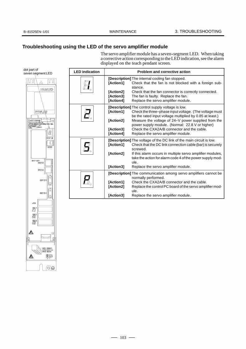
B--81525EN--1/01 3. TROUBLESHOOTINGMAINTENANCE
103
Troubleshooting using the LED of the servo amplifier moduleThe servo amplifier module has a seven--segment LED. When takinga corrective action corresponding to the LED indication, see the alarmdisplayed on the teach pendant screen.
LED indication Problem and corrective action
[Description] The internal cooling fan stopped.[Action1] Check that the fan is not blocked with a foreign sub-
stance.[Action2] Check that the fan connector is correctly connected.[Action3] The fan is faulty. Replace the fan.[Action4] Replace the servo amplifier module.
[Description] The control supply voltage is low.[Action1] Check the three--phase input voltage. (The voltage must
be the rated input voltage multiplied by 0.85 at least.)[Action2] Measure the voltage of 24--V power supplied from the
power supply module. (Normal: 22.8 V or higher)[Action3] Check the CXA2A/B connector and the cable.[Action4] Replace the servo amplifier module.
[Description] The voltage of the DC link of the main circuit is low.[Action1] Check that the DC link connection cable (bar) is securely
screwed.[Action2] If this alarm occurs in multiple servo amplifier modules,
take the action for alarm code 4 of the power supply mod-ule.
[Action3] Replace the servo amplifier module.
[Description] The communication among servo amplifiers cannot benormally performed.
[Action1] Check the CXA2A/B connector and the cable.[Action2] Replace the control PC board of the servo amplifier mod-
ule.[Action3] Replace the servo amplifier module.
dot part ofseven segment LED

3. TROUBLESHOOTING B--81525EN--1/01MAINTENANCE
104
LED indication Problem and corrective action
[Description1] The IPM alarm was detected in the servo amplifiermod-ule.
[Action1] Detach the motor power lines from the connectors CZ2of the servo amplifier modules, and turn the power on.a) If this alarm does not occur, go to Action 2.
b) If this alarm occurs, replace the servo amplifiermodule.
[Action2] Detach the motor power lines from the connectors CZ2of the servo amplifier modules, and check the insulationbetween PE and each of the motor power lines U, V, andW.a) If the insulation is deteriorated, go to Action 3.
b) If the insulation is normal, replace the servo amplifi-er module.
[Action3] Separate the motor and power line, then check whetherthe motor or power line has deteriorated insulation.a) If the motor insulation is deteriorated, replace the
motor.
b) If the power line insulation is deteriorated, examinethe robot interconnection cable or intra--robot cable.
“8.”, “9.”, and “A.” represent that an alarm occurs on the L--axis, M--axis, and N--axis respectively.
[Description2] The IPM alarm (overheat) was detected in the servoamplifier module.
[Action1] Check that the internal cooling fan does not stop.[Action2] Check that the motor is operated at its continuous rating
or lower.[Action3] Check that the cooling capability of the cabinet is not low-
ered. (Check the fan unit and heat exchanger.)[Action4] Check that the ambient temperature is not high.[Action5] Replace the servo amplifier module.
“8.”, “9.”, and “A.” represent that an alarm occurs on the L--axis, M--axis, and N--axis respectively.

B--81525EN--1/01 3. TROUBLESHOOTINGMAINTENANCE
105
LED indication Problem and corrective action
[Description] An abnormal current is flowing to the servo motor.[Action1] Check that the servo parameters are set to default val-
ues. If this alarm occurs only at a sudden accelerationor deceleration, the motor operating conditions may betoo harsh. Increase the acceleration/deceleration timeconstant and observe the operation.
[Action2] Detach the motor power lines from the connectors CZ2of the servo amplifier modules, then turn on the power.a) If this alarm does not occur, go to Action 2.
b) If this alarm occurs, replace the servo amplifiermodule.
[Action3] Detach the motor power lines from the connectors CZ2of the servo amplifier modules, then check the insulationbetween PE and each of the power lines U, V, and W.a) If the insulation is deteriorated, go to Action 3.
b) If the insulation is normal, replace the servo amplifi-er.
[Action4] Separate the motor and power line, then check whetherthe motor or power line has deteriorated insulation.a) If the motor insulation is deteriorated, replace the
motor.
b) If the power line insulation is deteriorated, examinethe robot interconnection cable and intra--robotcable.
“b”, “C”, and “d” represent that an alarm occurs on the L--axis, M--axis,and N--axis respectively.

3. TROUBLESHOOTING B--81525EN--1/01MAINTENANCE
106
(Check 1) On the status screen, check the position deviation in thestopped state. To display the position deviation, press thescreen selection key, and select STATUS from the menu.Press F1, [TYPE], select AXIS from the menu, then pressthe F4, PULSE.(Corrective action)Correct the parameters related to return to the referenceposition (positioning).
(Check 2) Check whether the motor axis can be positioned normally.(Corrective action)If the motor axis can be positioned normally, check themechanical unit.
(Check 3) Check the mechanical unit for backlash.(Corrective action)Replace a faulty key of motor shaft or other faulty parts.
(Check 4) If checks 1 to 3 show normal results(Corrective action)Replace the pulse coder and robot controller PC board.
3.8POSITION DEVIATIONFOUND IN RETURNTO THE REFERENCEPOSITION(POSITIONING)
B--81525EN--1/01 3. TROUBLESHOOTINGMAINTENANCE
107
(Check 1) Check the settings of parameters such as the position loopgain parameter.(Corrective action)Correct parameters.
(Check 2) Check the mechanical unit for backlash.(Corrective action)Replace a faulty key of motor shaft or other faulty parts.
3.9VIBRATIONOBSERVED DURINGMOVEMENT
3. TROUBLESHOOTING B--81525EN--1/01MAINTENANCE
108
The following explains checking and corrective action required if therobot cannot be operated manually after the controller is turned on:
(1) Check and corrective action to be made if manual operation isimpossible
(Check 1) Check whether the teach pendant is enabled.(Corrective action)Turn on the teach pendant “enable”.
(Check 2) Check whether the teach pendant is handled correctly.(Corrective action)To move an axis by manual operation, press the axisselection key and case shift key at the same time.Set the override for manual feed to a position other than theFINE and VFINE positions.
(Check 3) Check whether the ENBL signal of the peripheral devicecontrol interface is set to 1.(Corrective action)Place the peripheral device control interface in the ENBLstatus.
(Check 4) Check whether the HOLD signal of the peripheral devicecontrol interface is on (hold status). (Check whether thehold lamp on the teach pendant is on.)(Corrective action)Turn off the HOLD signal of the peripheral device controlinterface.
(Check 5) Check whether the previous manual operation has beencompleted.(Corrective action)If the robot cannot be placed in the effective area because ofthe offset of the speed command voltage preventing theprevious operation from being completed, check the positiondeviation on the status screen, and change the setting.
(Check 6) Check whether the controller is in the alarm status.(Corrective action)Release the alarm.
(2) Check and corrective action to be taken if the program cannot beexecuted
(Check 1) Check whether the ENBL signal for the peripheral-devicecontrol interface is on.(Corrective action)Put the peripheral-device control interface in the ENBL state.
(Check 2) Check whether the HOLD signal for the peripheral-devicecontrol interface is on. (Check whether the HOLD lamp onthe teach pendant is on.)(Corrective action)If the HOLD signal is on, turn it off.
3.10MANUALOPERATIONIMPOSSIBLE

B--81525EN--1/01 3. TROUBLESHOOTINGMAINTENANCE
109
(Check 3) Check whether the previous manual operation has beencompleted.(Corrective action)If the robot cannot be placed in the effective area because ofthe offset of the speed command voltage, which prevents theprevious operation from being completed, check the positiondeviation on the status screen, then change the setting.
(Check 4) Check whether the controller is in the alarm status.(Corrective action)Release the alarm.

4. PRINTED CIRCUIT BOARDS B--81525EN--1/01MAINTENANCE
110
4 PRINTED CIRCUIT BOARDS
The printed circuit boards are factory-set for operation. Usually, you donot need to set or adjust them. This chapter describes the standard settingsand adjustment required if a defective printed circuit board is replaced.It also describes the test pins and the LED indications.The standard printed circuit board includes the main unit printed circuitboard and one or more cards or modules installed horizontally to themain--unit printed--circuit board.These PC boards have interface connectors, LED indicators, and a plasticpanel at the front. At the rear, there is a backplane connector.

B--81525EN--1/01 4. PRINTED CIRCUIT BOARDSMAINTENANCE
111
CPU card
Total version
Axis control card
FROM/SRAM moduleunder the CPU card DC/DC converter module
Fig.4.1 Robot controller PC board
Name Board Specification Note
Robot controller PCboard A16B--3200--0450 I/O Link master/slave switche-
able, SDI/SDO = 28/24
DC/DC convert module A20B--8100--0721
CPU card A20B--3300--0106 SDRAM 8M (Standard)
A20B--3300--0107 SDRAM 16M
Axis control card A20B--3300--0241 6--axis
FROM/SRAM module A20B--3900--0181 FROM 16M, SRAM 0.5M :Standard
A20B--3900--0160 FROM 16M, SRAM 1MB
A20B--3900--0161 FROM 16M, SRAM 2MB
A20B--3900--0162 FROM 32M, SRAM 3MB
4.1ROBOT CONTROLLERPC BOARD(A16B--3200--0450)

4. PRINTED CIRCUIT BOARDS B--81525EN--1/01MAINTENANCE
112
(1) LEDsSeven segment LED Description
A parity alarm occurred in a RAM of the main CPUcard on the Robot controller PC board.
A parity alarm occurred in a RAM of the FROM/SRAM module on the Robot controller PC board.
“2”, “3”, and “4” are not displayed.
A servo alarm occurred on the Robot controller PCboard.
SYSEMG occurred.
SYSFAIL occurred.This number appears temporarily after the power isswitched on, but it is not abnormal.

B--81525EN--1/01 4. PRINTED CIRCUIT BOARDSMAINTENANCE
113
Status LED Description
STATUSLED
Indicates the system operating status.
Status LED Description
FUSEALARMLED
A fuse (FUS1 or FUS2) was blown.
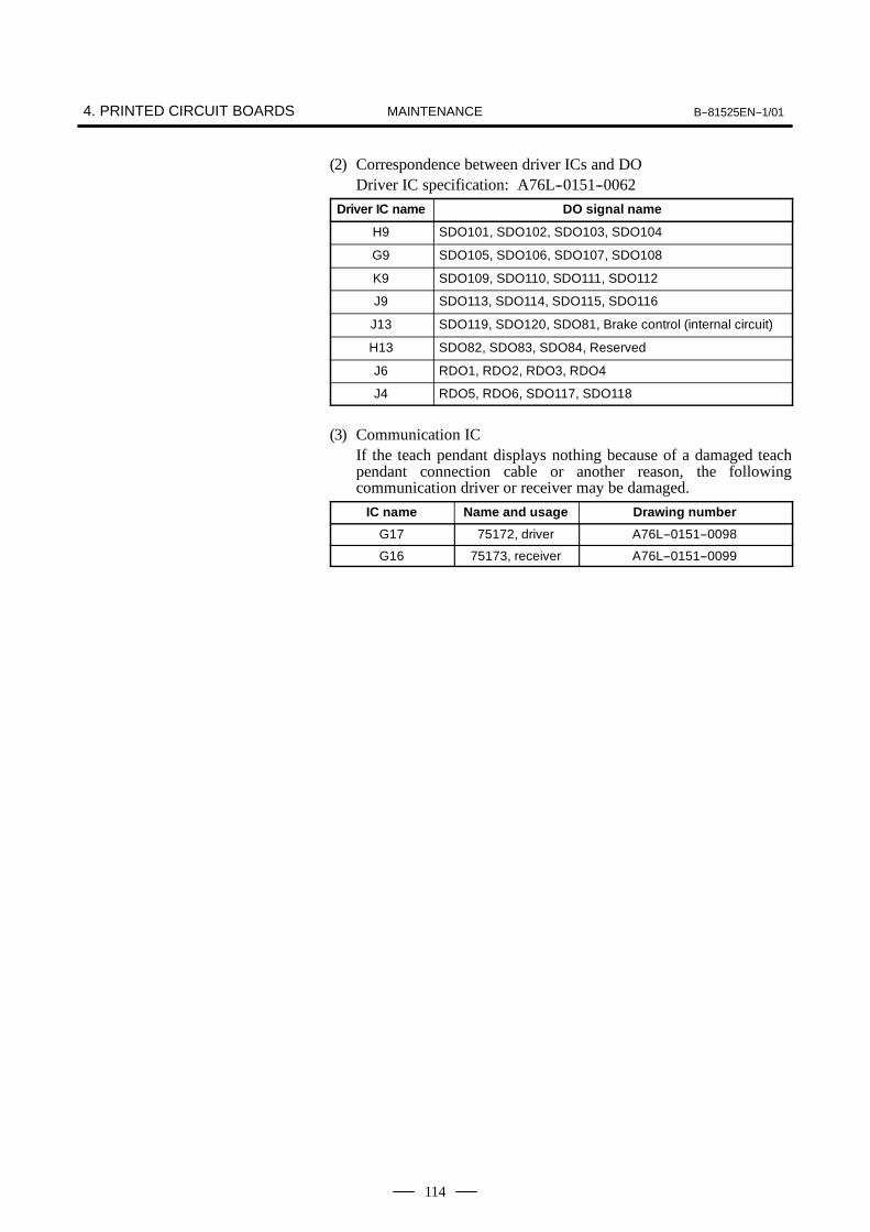
4. PRINTED CIRCUIT BOARDS B--81525EN--1/01MAINTENANCE
114
(2) Correspondence between driver ICs and DODriver IC specification: A76L--0151--0062
Driver IC name DO signal name
H9 SDO101, SDO102, SDO103, SDO104
G9 SDO105, SDO106, SDO107, SDO108
K9 SDO109, SDO110, SDO111, SDO112
J9 SDO113, SDO114, SDO115, SDO116
J13 SDO119, SDO120, SDO81, Brake control (internal circuit)
H13 SDO82, SDO83, SDO84, Reserved
J6 RDO1, RDO2, RDO3, RDO4
J4 RDO5, RDO6, SDO117, SDO118
(3) Communication ICIf the teach pendant displays nothing because of a damaged teachpendant connection cable or another reason, the followingcommunication driver or receiver may be damaged.
IC name Name and usage Drawing number
G17 75172, driver A76L--0151--0098
G16 75173, receiver A76L--0151--0099

B--81525EN--1/01 4. PRINTED CIRCUIT BOARDSMAINTENANCE
115
Total version
Fig.4.2 Emergency stop control PC board
4.2EMERGENCY STOPPC BOARD(A20B--1008--0022,--0023)

4. PRINTED CIRCUIT BOARDS B--81525EN--1/01MAINTENANCE
116
Total version
Fig.4.3 Backplane PC Board
4.3BACKPLANE PCBOARD(A20B--2003--0330)

B--81525EN--1/01 5. SERVO AMPLIFIERSMAINTENANCE
117
5 SERVO AMPLIFIERS
The servo amplifiers are factory-set for operation. Usually, you do notneed to set or adjust them.This chapter describes the standard settings and adjustment required if adefective servo amplifier is replaced. It also describes the use of test pinsand meanings of the LED indications.
Table 5 Servo amplifier specifications
Robot Power supply module Servo amplifier module1 Servo amplifier module2
LR Mate 100iB
A06B--6115--H001(αPSMR--1i)
A06B--6114--H205(αSVM--20/20i)
A06B--6114--H302(αSVM--10/10/10i)
LR Mate 100iB L M L M NJ1 J2 J3 J4 J5
LR Mate 200iB
A06B--6115--H001(αPSMR--1i)
A06B--6114--H302(αSVM--10/10/10i)
A06B--6114--H302(αSVM--10/10/10i)
LR Mate 200iB L M N L M NJ1 J2 J3 J4 J5 J6
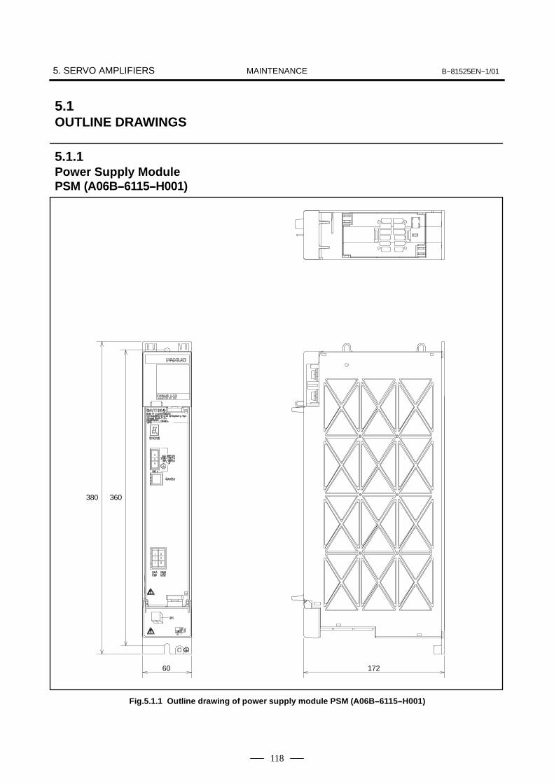
5. SERVO AMPLIFIERS B--81525EN--1/01MAINTENANCE
118
380 360
60 172
Fig.5.1.1 Outline drawing of power supply module PSM (A06B--6115--H001)
5.1OUTLINE DRAWINGS
5.1.1Power Supply ModulePSM (A06B--6115--H001)

B--81525EN--1/01 5. SERVO AMPLIFIERSMAINTENANCE
119
380 360
60 172
Fig.5.1.2 Outline drawing of servo amplifier modules (A06B--6114--H205, A06B--6114--H302)
5.1.2Servo Amplifier Module(A06B--6114--H205,A06B--6114--H302)

5. SERVO AMPLIFIERS B--81525EN--1/01MAINTENANCE
120
The power supply module has a seven--segment LED. When taking acorrective action corresponding to the LED indication, see the alarmdisplayed on the teach pendant screen.
LED indication Description
The magnetic contactor controlled by the power supply module is inthe off state and is not ready for driving the motor.
The magnetic contactor controlled by the power supply module is inthe on state and is ready for driving the motor.
The voltage of the DC link of the main circuit is low.
The main circuit cannot be charged within a predetermined period.
The control power voltage is low.
The voltage of the DC link of the main circuit is too high.
The regeneration amount is too large.
The regenerative resistor was heated.
The input power is in the open--phase state.
5.2LED OF SERVOAMPLIFIER
5.2.1LED of Power SupplyModule
dot part ofseven segment LED

B--81525EN--1/01 5. SERVO AMPLIFIERSMAINTENANCE
121
The servo amplifier module has a seven--segment LED. When taking acorrective action corresponding to the LED indication, see the alarmdisplayed on the teach pendant screen.
LED indication Description
The main circuit in the servo amplifier module is in the off state and isnot ready for driving the motor.
The main circuit in the servo amplifier module is in the on state and isready for driving the motor.
The internal cooling fan stopped.
The control power voltage is low.
The voltage of the DC link of the main circuit is low.
The communication among servo amplifier modules cannot be normal-ly performed.
a) The IPM alarm was detected in the servo amplifier module.
b) The IPM alarm (overheat) was detected in the servo amplifier mod-ule.
“8.”, “9.”, and “A.” represent that an alarm occurs on the L--axis, M--axis, and N--axis respectively.
An abnormal current is flowing to the servo motor.
“b”, “C”, and “d” represent that an alarm occurs on the L--axis, M--axis,and N--axis respectively.
5.2.2LED of Servo AmplifierModule
dot part ofseven segment LED

B--81525EN--1/01MAINTENANCE6. SETTING THE POWER SUPPLY
122
6 SETTING THE POWER SUPPLY
The power supply is factory-set for operation. Usually, you do not needto set or adjust it.

B--81525EN--1/01 MAINTENANCE 6. SETTING THE POWER SUPPLY
123
+24E
+24V--15V+15V+5V+3.3V
Backplane
AC input220, 380, 415,440, 500 VAC3φ
Process I/O
CRM2CRM4
+24F+24E FUSE1
board
+24V
JD17
+24E
+24E
+24E
CRM81
CRM79
CRM82
FUS2
FUS1 CP5
CP8B
BATTERYDC/DCconvertermodule+5V, +3.3V+15V, --15V
FAN
Powersupplyunit
AC/DC+24V
CN1
FUS3 FUS4 FUS5
FU1CX1
CZ1
Power supply module
Servo amplifier
Motor
End Effector
Motor powersupplyMotor brake
Pulsecoder
Robot
Peripheral device(option)
Handy file etc.
Peripheral device
Teach pendant
+24T
CP5B CRS1Monitor circuit
Brakecircuit
Emergency stopunit
Circuitprotector
200VAC
3φ
2φ 200VAC 2φ
200VAC
Magneticcontactor(MCC)
Main circuitDC link
AC/DC+24V
DC/DC+5V
Invertercircuit
CXA2A L+, L--
CXA2B
JF1--3
L+, L--
CZ2 L--N
Emergen-cy stopcircuit
Servoamplifiermodule
Emergency stopprint board
Robot controllerP.C. board
+24V
+24E
Peripheral device(option)
TBEB3
CP5A CRR77
regenerativeresistor
Circuitprotector
Trans-former
Fig. 6.1 Block diagram of the power supply
6.1BLOCK DIAGRAMSOF THE POWERSUPPLY

B--81525EN--1/01MAINTENANCE6. SETTING THE POWER SUPPLY
124
The power supply unit need not be set or adjusted.
Table 6.2 Rating of the Power supply unit
Output Rated voltage Tolerance
+24V +24V +23V to +25V
The power supply module need not be set or adjusted.
Table 6.3 Rating of the Power supply module
Output Rated voltage Tolerance
+5V +5.1V 3%
+3.3V +3.3V 3%
+15V +15V 10%
--15V --15V 10%
6.2CHECKING THEPOWER SUPPLYUNIT
6.3CHECKING THEPOWER SUPPLYMODULE

B--81525EN--1/01 MAINTENANCE 6. SETTING THE POWER SUPPLY
125
One of the transformer connections is selected according to the powervoltage.
Rated voltage Transformer specification
220, 380, 415,440, 500V A80L--0022--0009
Transformer
Teminal arrangement
Fig.6.4 Transformer Installation Position and Terminal Block
Table 6.4 Transformer Tap Selection
PowerPrimary side tap connection
Connec-Powervoltage
L1 L2 L3 Connection line
Connection type
220V 4 9 14 4-15 9-5 14-10 Delta n
380V 4 9 14
415V 3 8 135 10 15 Star Y
440V 2 7 125-10-15 Star Y
500V 1 6 11
6.4SELECTING THETRANSFORMERCONNECTION
7. REPLACING A UNIT B--81525EN--1/01MAINTENANCE
126
7 REPLACING A UNIT
This section explains how to replace each unit in the control section.
WARNINGBefore you start to replace a unit, turn off the control unitmain power. Also keep all machines in the area of the controlunit switched off. Otherwise, you could injure personnel ordamage equipment.

B--81525EN--1/01 7. REPLACING A UNITMAINTENANCE
127
CAUTIONSWhen you replace printed--circuit boards, observe thefollowing cautions:
1 Keep the control unit power switched off.2 When you remove a printed--circuit board, do not touch the
semiconductor devices on the board with your hand ormake them touch other components.
3 Make sure that the replacement printed--circuit board hasbeen set up appropriately. (Setting plug etc.)
4 If the backplane board, power supply unit, or Robotcontroller PC board (including cards and modules) isreplaced, it is likely that robot parameters and taught dataare lost. Before you start to replace these components, savea backup copy of the robot parameters and taught data toa memory card, floppy disk, or any other external memorydevice.
5 Before you disconnect a cable, note its location. If a cableis detached for replacement, reconnect it exactly as before.
7.1REPLACING THEPRINTED--CIRCUITBOARDS

7. REPLACING A UNIT B--81525EN--1/01MAINTENANCE
128
When replacing the backplane board, do so together with the plastic rack.
(1) Detach the cables from the robot controller PC board and boards onthe backplane board.
CAUTIONWhen you remove the main robot controller PC Board, besure that the battery is good (3.1--3.3VDC) and it is installedcorrectly. USE STATIC PROTECTION.
(2) Remove the robot controller PC board and boards from the rack. (SeeSection 7.1.2.)
(3) Detach the grounding cable from the backplane unit.(4) Loosen the retaining screws in the upper section of the rack. Remove
the retaining screws from the lower section of the rack.(5) Side rack up and out.(6) To replace the backplane and rack, reverse steps (1) -- (6).
CAUTIONThere is a possibility of data loss when a backplane--mounted printed circuit board is replaced. Be sure to backup all program and setup data on a floppy disk beforeproceeding.
M5 nut (2 places)
Backplane board
Fig.7.1.1 Replacing the Backplane Board
7.1.1Replacing theBackplane Board (Unit)

B--81525EN--1/01 7. REPLACING A UNITMAINTENANCE
129
The backplane unit incorporates the power unit, Robot controller PCboard, and option boards. There are two types of option boards: Full--sizeboard and mini--size board. A full--size board occupies one slot. Amini--size board uses part of a full--size board.
CAUTIONBefore starting replacement, turn off the control unit mainpower. The robot controller PC board is equipped withbattery--backed memory devices for holding robotparameters and taught data, for example. When the Robotcontroller PC board is replaced, the data in the memorydevices is lost.
(1) Detach the cable from the printed--circuit board, whichever is to bereplaced.
(2) Pinch the barbed handles on the upper and lower sections of the boardto unlatch it, then pull it toward you.
(3) Place the replacement board on the rail in the appropriate slot of therack, then push it in gently by the handles until it is latched.
(4) There are two rails in the robot controller PC board SLOT (slot 1).When inserting the robot controller PC board, align it to theright--side rail.
Slot 1
Slot 2
Slot 1
Slot 10
Slot 9Rail(Left)
Rail(Right)
Barbedhandles
Barbedhandles
Option slot
zoom
Fig.7.1.2 Replacing the Robot Controller PC Board and Printed--CircuitBoards on the Backplane Unit
7.1.2Replacing the RobotController PC Boardand Printed--CircuitBoards on theBackplane Unit
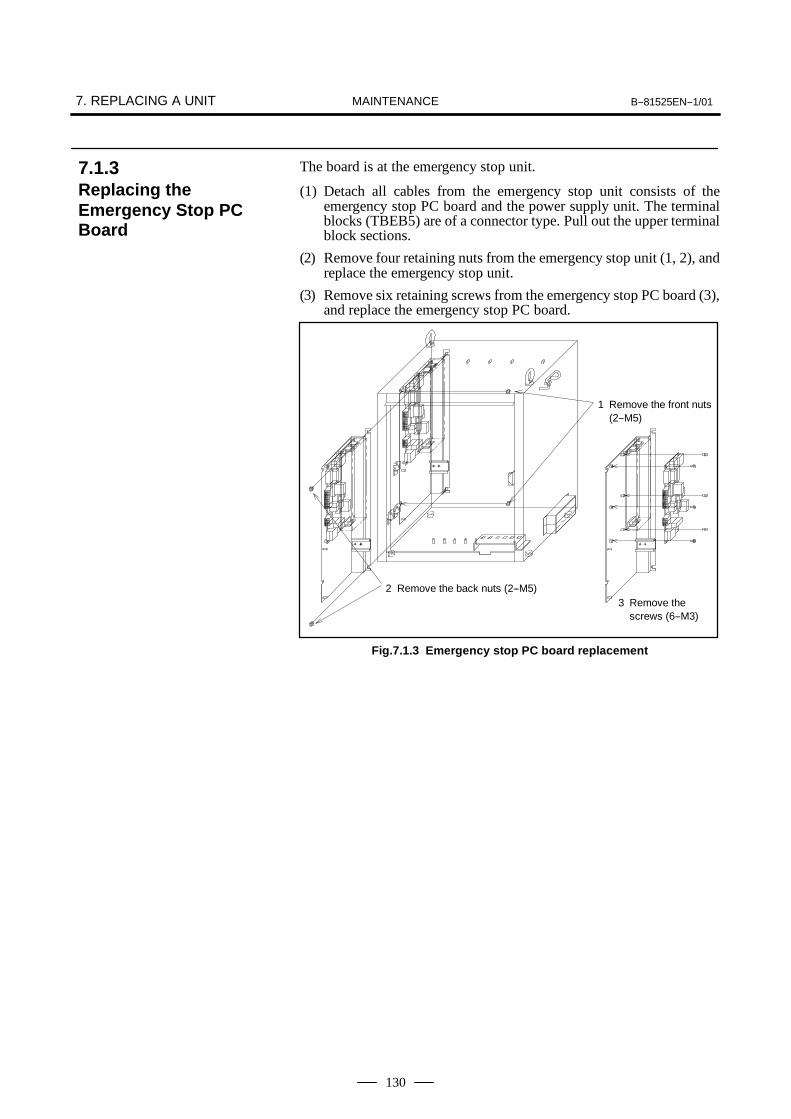
7. REPLACING A UNIT B--81525EN--1/01MAINTENANCE
130
The board is at the emergency stop unit.
(1) Detach all cables from the emergency stop unit consists of theemergency stop PC board and the power supply unit. The terminalblocks (TBEB5) are of a connector type. Pull out the upper terminalblock sections.
(2) Remove four retaining nuts from the emergency stop unit (1, 2), andreplace the emergency stop unit.
(3) Remove six retaining screws from the emergency stop PC board (3),and replace the emergency stop PC board.
2 Remove the back nuts (2--M5)
1 Remove the front nuts(2--M5)
3 Remove thescrews (6--M3)
Fig.7.1.3 Emergency stop PC board replacement
7.1.3Replacing theEmergency Stop PCBoard

B--81525EN--1/01 7. REPLACING A UNITMAINTENANCE
131
CAUTIONBefore you start to replace a card or module, make a backupcopy of robot parameters and taught data. If the FROM/SRAMmodule is replaced, memory contents are lost.
Demounting a Card(1) Pull outward the clip of each of the two spacers used to secure the card
PCB, then release each latch.(2) Extract the card upward.
Card Card
Card
Card
Spacer
Spacer
Connector
Connector
Card
Fig.7.2 (a) Demounting a card
7.2REPLACING CARDSAND MODULES ONTHE ROBOTCONTROLLER PCBOARD

7. REPLACING A UNIT B--81525EN--1/01MAINTENANCE
132
Mounting a Card(1) Check that the clip of each of the two spacers is latched outward, then
insert the card into the connector.(2) Push the clip of each spacer downward to secure the card PCB.
Card
CardCard
Card
Spacer
Spacer
Connector
Connector
CardCard
Fig.7.2 (b) Mounting a card

B--81525EN--1/01 7. REPLACING A UNITMAINTENANCE
133
Demounting a module
CAUTIONWhen replacing the module, be careful not to touch themodule contact. If you touch the contact inadvertently, wipeout dirt on the contact with a clean cloth.
(1) Move the clip of the socket outward. (a)(2) Extract the module by raising it at a 30 degree slant and pulling
outward.
Mounting a module(1) Insert the module at a 30 degree slant into the module socket, with
side B facing upward. (b)(2) Push the module inward and downward until it is locked. (c)
(a)
(b)
(c)
Fig.7.2 (c) Demounting/Mounting a module
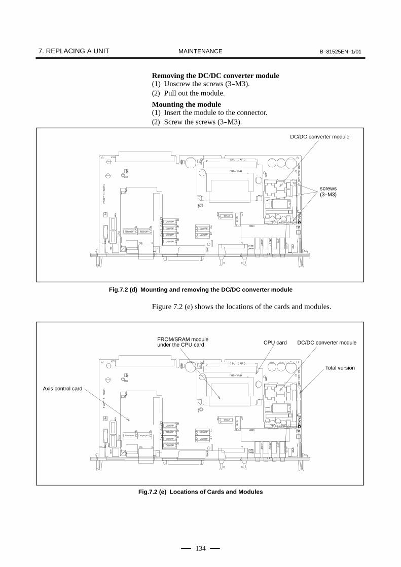
7. REPLACING A UNIT B--81525EN--1/01MAINTENANCE
134
Removing the DC/DC converter module(1) Unscrew the screws (3--M3).(2) Pull out the module.
Mounting the module(1) Insert the module to the connector.(2) Screw the screws (3--M3).
DC/DC converter module
screws(3--M3)
Fig.7.2 (d) Mounting and removing the DC/DC converter module
Figure 7.2 (e) shows the locations of the cards and modules.
CPU card
Total version
Axis control card
FROM/SRAM moduleunder the CPU card DC/DC converter module
Fig.7.2 (e) Locations of Cards and Modules

B--81525EN--1/01 7. REPLACING A UNITMAINTENANCE
135
WARNINGBefore you start replacement procedure, turn off the mainpower to the control unit. Otherwise you could injurepersonnel or damage equipment.
(1) Detach the cable from the transformer.
(2) Remove the two nuts (M5) securing the transformer, then replace thetransformer.
(3) Re--connect the cable.
Remore the nuts (2--M5)
Fig.7.3.1 Replacing the brake power transformer
7.3REPLACING THETRANSFORMER
7.3.1Replacing the BrakePower Transformer

7. REPLACING A UNIT B--81525EN--1/01MAINTENANCE
136
(1) Detach the cables from the transformer.
(2) Remove the two screws (M5) securing the transformer and thenreplace the transformer.
(3) Connect the detached cables to the transformer.
Remove two screws (M5)
Fig.7.3.2 Replacing the Power Transformer
7.3.2Replacing the PowerTransformer

B--81525EN--1/01 7. REPLACING A UNITMAINTENANCE
137
WARNINGBefore you start replacement, turn off the control unit mainpower.
B--cabinet(1) Detach the cables from the emergency stop unit.
(2) Remove retaining screws (4--M4) from the emergency stop unit, andreplace the emergency stop unit.
(3) Reconnect the cables.
2 Remove the back nuts(2--M5) screws
1 Remove the front nuts(2--M5) screws
Nut (4--M5)
Fig.7.4 Replacing the Emergency Stop Unit
7.4REPLACING THEEMERGENCY STOPUNIT
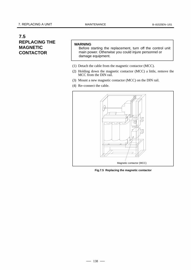
7. REPLACING A UNIT B--81525EN--1/01MAINTENANCE
138
WARNINGBefore starting the replacement, turn off the control unitmain power. Otherwise you could injure personnel ordamage equipment.
(1) Detach the cable from the magnetic contactor (MCC).
(2) Holding down the magnetic contactor (MCC) a little, remove theMCC from the DIN rail.
(3) Mount a new magnetic contactor (MCC) on the DIN rail.
(4) Re--connect the cable.
Magnetic contactor (MCC)
Fig.7.5 Replacing the magnetic contactor
7.5REPLACING THEMAGNETICCONTACTOR

B--81525EN--1/01 7. REPLACING A UNITMAINTENANCE
139
WARNINGBefore you start replacement, turn off the control unit mainpower. Otherwise you could injure personnel or damageequipment.
The following is the procedure for replacing the power supply module andservo amplifier module.
(1) Detach the cable from the servo amplifier. Remove the jumperconnecting the DC link (L+ and L--).
(2) Remove the two nuts from the top of the servo amplifier.
(3) Mount a new servo amplifier, reversing the removal step of (2).
(4) Re--connect the cable and re--mount the jumper connecting the DClink (L+ and L--).
Nut(2--M5)
Power supplymodule
servo amplifiermodule
Fig.7.6 Replacing the servo Amplifier
7.6REPLACING SERVOAMPLIFIERS

7. REPLACING A UNIT B--81525EN--1/01MAINTENANCE
140
The specifications of the teach pendant vary with its use. When youreplace the teach pendant, check its specifications carefully.
(1) Be sure that the power of a robot controller is off.
(2) Detach the cable from the teach pendant.
(3) Replace the teach pendant.
Detach or attach the cable by rotatingthe connector retaining ring.
Fig.7.7 Replacing the Teach Pendant
7.7REPLACING THETEACH PENDANT

B--81525EN--1/01 7. REPLACING A UNITMAINTENANCE
141
The control section fan motor can be replaced without using a tool. Thefan motor is mounted on the fan unit rack.
(1) Be sure that the power of a robot controller is off.
(2) Put your finger in the dent in the upper section of the fan unit, and pullthe fan unit until it is unlatched.
(3) Lift the fan unit slightly, and dismount it from the rack.
(4) Place a replacement fan on the upper section of the rack, and slide itgently until it is latched.
Fan motor connector
Fan motor
Pull the fan motor unittoward you to unlatch it.
Fig.7.8 Replacing the Control Section Fan Motor
7.8REPLACING THECONTROL SECTIONFAN MOTOR
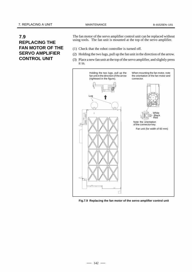
7. REPLACING A UNIT B--81525EN--1/01MAINTENANCE
142
The fan motor of the servo amplifier control unit can be replaced withoutusing tools. The fan unit is mounted at the top of the servo amplifier.
(1) Check that the robot controller is turned off.
(2) Holding the two lugs, pull up the fan unit in the direction of the arrow.
(3) Place a new fan unit at the top of the servo amplifier, and slightly pressit in.
Holding the two lugs, pull up thefan unit in the direction of the arrow(rightward in the figure).
When mounting the fan motor, notethe orientation of the fan motor andconnector.
Lug
WhiteBlackRed
Note the orientationof the connector key.
Fan unit (for width of 60 mm)
Fig.7.9 Replacing the fan motor of the servo amplifier control unit
7.9REPLACING THEFAN MOTOR OF THESERVO AMPLIFIERCONTROL UNIT

B--81525EN--1/01 7. REPLACING A UNITMAINTENANCE
143
WARNINGBefore starting the replacement, turn off the control unitmain power. Never touch the fan motor while it is rotating.
Door fan unit
(1) Unscrew the four fastening screws (M4).
(2) Detach the cable from the fan unit.
(3) Mount a spare fan unit, reversing the removal procedure.Heat exchanger
(1) Detach the cable from the heat exchanger.
(2) Remove the six fastening nuts (M4), and pull the heat exchangertoward you.
(3) Detach the wiring from the door fan unit.
(4) Mount a spare heat exchanger, reversing the removal procedure.
Screws (4--M4)Nut (4--M5)
Door fan unit
Heat exchange
Fig.7.10 Replacing the door fan unit and heat exchanger
7.10REPLACING THEDOOR FAN UNIT ANDHEAT EXCHANGER

7. REPLACING A UNIT B--81525EN--1/01MAINTENANCE
144
(1) Detach the cable from the circuit protector on the operator panel andthe grounding line from the door.
(2) Detach the cable (JD17) from the robot controller PC board and thecable (CRT12) from the emergency stop PC board.
(3) Unscrew the four screws (M3) fastening the operator panel, andremove the operator panel.
(4) Mount a new operator panel, reversing the removal steps of (1) to (3).
Screw (4--M3)
Fig.7.11 Replacing the operator panel
NOTEThe operator panel comprises the panel itself and thecables connected to the robot controller PC board andemergency stop PC board.
7.11REPLACING THEOPERATOR PANEL

B--81525EN--1/01 7. REPLACING A UNITMAINTENANCE
145
The power supply unit is mounted on the emergency stop unit.
(1) Detach all the cables from the emergency stop unit (emergency stopPC board and power supply unit).
(2) Pull out the connector--type terminal block (TBEB5) at the top.
(3) Remove the four nuts (1 and 2) fastening the emergency stop unit, andremove the emergency stop unit.
(4) Unscrew the four screws fastening the power supply unit, and replacethe power supply unit.
1 Remove the front nuts(2--M5)
3 Remove the screws (4--M3)
2 Remove the back nuts (2--M5)
Fig.7.12 Replacing the power supply unit
7.12REPLACING THEPOWER SUPPLYUNIT

7. REPLACING A UNIT B--81525EN--1/01MAINTENANCE
146
If a fuse of the control unit is blown, find out the cause, take an appropriateaction, then replace the fuse.
The robot controller PC board has the following fuses.
FUS1: For detecting a problem in the circuit on the robot controller PCboard: A60L--0001--0046#7.5If this fuse is blown, the DC/DC converter module or a deviceconnected to the RS--232--C/RS--422 port may be faulty. If thedevice connected to the RS--232--C/RS--422 port is not faulty,replace the DC/DC converter module.
FUS2: For protecting the 24V output to the peripheral device:A60L--0001--0046#7.5If this fuse is blown, the wiring to the peripheral device and a cablemay be incorrect or damaged.
FUS1 FUS2
Fig.7.13.1 Replacing a fuse on the robot controller PC board
7.13REPLACING A FUSE
7.13.1Replacing a Fuse onthe Robot ControllerPC Board

B--81525EN--1/01 7. REPLACING A UNITMAINTENANCE
147
The emergency stop PC board has the following fuses.
FUS3: For monitoring the emergency stop circuit: A60L--0001--0046#1.0If this fuse is blown, the emergency stop PC board may be faulty.Replace the emergency stop PC board.
FUS4: For protecting the 24V output to the emergency stop circuit andteach pendant: A60L--0001--0046#1.0If this fuse is blown, the emergency stop circuit may be incorrectlyrouted, or the teach pendant or teach pendant cable may be faulty.Check the routing of the emergency stop circuit, and replace theteach pendant and teach pendant cable.
FUS5: For monitoring the emergency stop circuit: A60L--0001--0245#GP20If the fuse is blown, the brake circuit may be faulty. Examine thebrake, robot, and robot interconnection cable. Alternatively,replace the emergency stop PC board.
FUS3
FUS4
FUS5
Emergency stop P.C.board
Fig.7.13.2 Replacing a fuse on the emergency stop PC board
7.13.2Replacing a Fuse onthe Emergency StopPC Board

7. REPLACING A UNIT B--81525EN--1/01MAINTENANCE
148
The power supply module has the following fuse.
FU1: For protecting the 200VAC input for generating power to thecontrol circuit: A60L--0001--0359If the fuse is blown, the power supply module may be faulty.Replace the power supply module.
FU1
Remove the face plate
Fig.7.13.3 Replacing the fuse on the power supply module
7.13.3Replacing the Fuse onthe Power SupplyModule
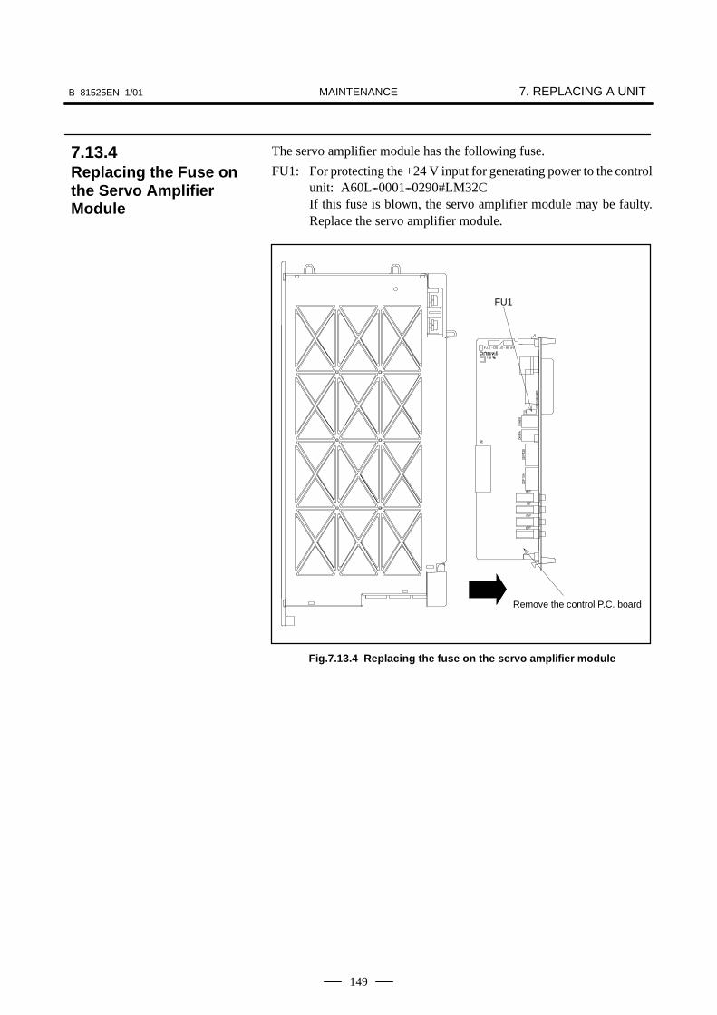
B--81525EN--1/01 7. REPLACING A UNITMAINTENANCE
149
The servo amplifier module has the following fuse.
FU1: For protecting the +24 V input for generating power to the controlunit: A60L--0001--0290#LM32CIf this fuse is blown, the servo amplifier module may be faulty.Replace the servo amplifier module.
FU1
Remove the control P.C. board
Fig.7.13.4 Replacing the fuse on the servo amplifier module
7.13.4Replacing the Fuse onthe Servo AmplifierModule
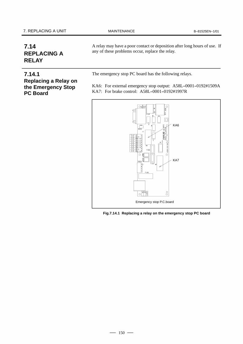
7. REPLACING A UNIT B--81525EN--1/01MAINTENANCE
150
A relay may have a poor contact or deposition after long hours of use. Ifany of these problems occur, replace the relay.
The emergency stop PC board has the following relays.
KA6: For external emergency stop output: A58L--0001--0192#1509AKA7: For brake control: A58L--0001--0192#1997R
KA6
KA7
Emergency stop P.C.board
Fig.7.14.1 Replacing a relay on the emergency stop PC board
7.14REPLACING ARELAY
7.14.1Replacing a Relay onthe Emergency StopPC Board

B--81525EN--1/01 7. REPLACING A UNITMAINTENANCE
151
The programs, and system variables are stored in the SRAM in the Robotcontroller PC board. The power to the SRAM memory is backed up bya lithium battery mounted on the front panel of the Robot controller PCboard. The above data is not lost even when the main battery goes dead.A new battery can maintain the contents of memory for about 4 years(Note).When the voltage of the battery becomes low, the battery alarm LED onthe operator panel is lit, and the low--voltage battery alarm (system--035)is displayed on the teach pendant. When this alarm is displayed, replacethe battery as soon as possible. In general, the battery can be replacedwithin one or two weeks, however, this depends on the systemconfiguration.If the battery voltage gets lower, it becomes impossible to back up thecontent of the SRAM. Turning on the power to the in this state causessystem not to start and LED of seven segment on the Robot controller PCboard to be displayed “1” because the contents of memory are lost. Clearthe entire SRAM memory and reenter data after replacing the battery.Important data should be saved to the memory card or floppy diskbeforehand in case of emergency.When replacing the memory backup battery, do so while the robotcontroller is turned off in case of emergency.
NOTEIn a newly introduced robot, the battery is factory--installed.Battery replacement may, therefore, be needed within 4years after the introduction of the robot.
(1)Prepare a new lithium battery (ordering drawing number:A02B--0200--K102).
(2)Turn the robot controller on for about 30 seconds.(3)Turn the robot controller off.(4)Remove the old battery from the top of the Robot controller PC board.
First unlatch the battery, remove it from the battery holder, and detachits connector.
7.15REPLACINGBATTERY
7.15.1Battery for MemoryBackup (3 VDC)
Replacing the lithiumbattery
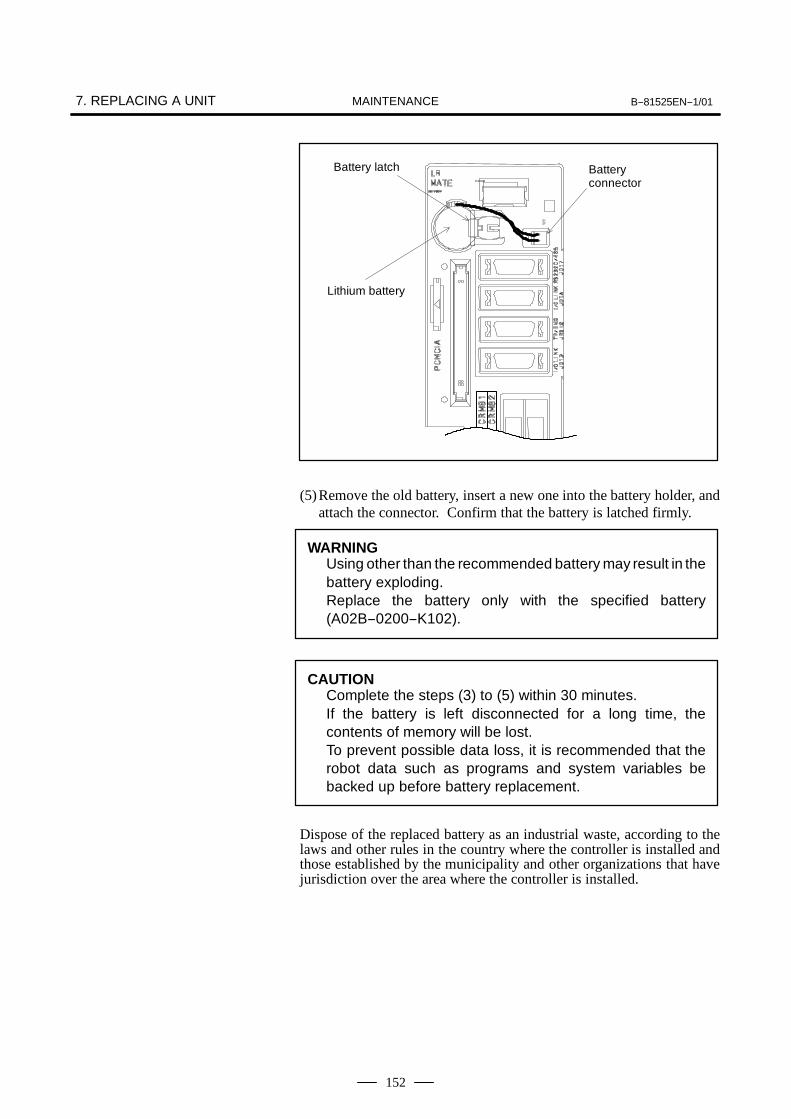
7. REPLACING A UNIT B--81525EN--1/01MAINTENANCE
152
Battery latch
Lithium battery
Batteryconnector
(5)Remove the old battery, insert a new one into the battery holder, andattach the connector. Confirm that the battery is latched firmly.
WARNINGUsing other than the recommended battery may result in thebattery exploding.Replace the battery only with the specified battery(A02B--0200--K102).
CAUTIONComplete the steps (3) to (5) within 30 minutes.If the battery is left disconnected for a long time, thecontents of memory will be lost.To prevent possible data loss, it is recommended that therobot data such as programs and system variables bebacked up before battery replacement.
Dispose of the replaced battery as an industrial waste, according to thelaws and other rules in the country where the controller is installed andthose established by the municipality and other organizations that havejurisdiction over the area where the controller is installed.

III CONNECTION

B--81525EN--1/01 1. GENERALCONNECTIONS
155
1 GENERAL
This chapter describes the connection and the installation of the electricalinterface.

2. BLOCK DIAGRAM B--81525EN--1/01CONNECTIONS
156
2 BLOCK DIAGRAM
Following are the block diagrams of the electrical interface connection forR--J3iB Mate.
R--J3iB Mate controller
RobotcontrolP.C. board Operation
panel
Peripheral device
RS--232--CRS--422/485
Teach pendant
Emergency stop
Emergencystop unit
Powersupplyunit
Emergency stopP.C.board
(Note2)
Transformer
Fan
Fuse
MCC Servoamplifier
(Brake)
(RDI/RDO)
Power
Pulse coder
Robot
Cir-cuitpro-tec-tor
Cir-cuitpro-tec-tor Tr
ansf
orm
er
220, 380,415, 440,500VAC
NOTETranceformer is installed when the robot is for 6--axes brakespecification.

B--81525EN--1/01 3. CONNECTION DETAILSCONNECTIONS
157
3 CONNECTION DETAILS
CP8B
CP5
JRS12
PCMCIA
COP10A
CRM82
JD17
JD1A
JD1B
CRM79
CRM81
PCMCIA
EMGIN1, 2
SVOFF1, 2CP5B
CRS24EMGOUT11, 12
EMGOUT21, 22
CRS1
RS--232--C or RS--422/485
Robot controllerPC board
Battery
Emergencystop unit
Emergencystop circuit
Teach pendant
Servo amplifier
Mechanical unit
I/O Link (master)
I/O Link (slave : option)
Peripheral device
Peripheral device (option)
FENCE1, 2

3. CONNECTION DETAILS B--81525EN--1/01CONNECTIONS
158
When the stand--alone controller is used, an optional power cable can be specified.
A grounding stud is providedbeside the circuit protector.Connect the primary powerground wire to this stud. Usean M4 crimp terminal.
Circuit protectorTerminal is M4.
To primary power supply3Φ220/380/415/440/500VAC
Use the cable holders areprovided at these locations.(3 locations)
NOTEConnect the primary power cable to the circuit protector. Connect the primarypower ground wire to the grounding stud, located beside the circuit protector.
The power supply cables are optional.
3.1CONNECTING THEPOWER SUPPLYCABLE

B--81525EN--1/01 3. CONNECTION DETAILSCONNECTIONS
159
Table 3.2 Types of FANUC I/O Links
No Name Drawing numberI/O Link
RemarksNo. Name Drawing numberMaster Slave
Remarks
1 Robot controller PC board A16B--3200--0450 f(*) f(*) Standard
NOTEThe I/O Link of the robot controller PC board is in the mastermode by default. The I/O Link can be used in the slavemode by changing the software parameter setting.
Refer to the operator’s manual for setting slave mode.
3.2FANUC I/O LINK
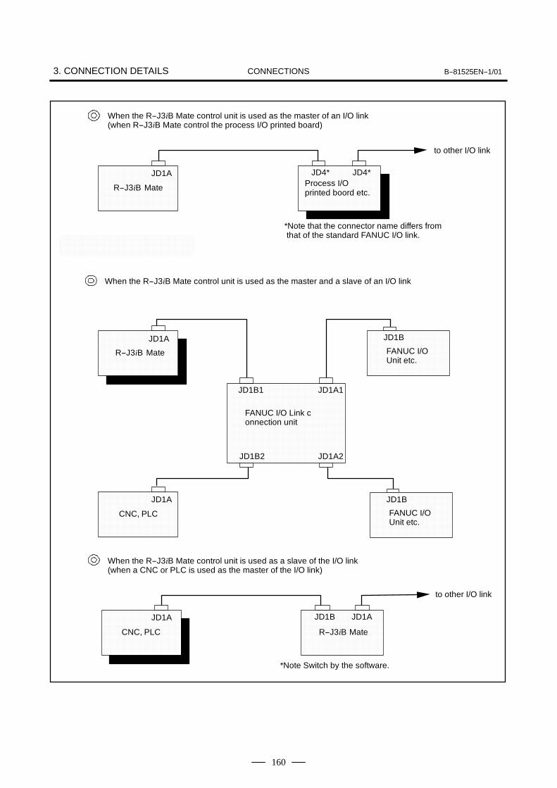
3. CONNECTION DETAILS B--81525EN--1/01CONNECTIONS
160
When the R--J3iB Mate control unit is used as the master of an I/O link(when R--J3iB Mate control the process I/O printed board)
R--J3iB Mate
JD1A JD4*Process I/Oprinted boord etc.
to other I/O link
*Note that the connector name differs fromthat of the standard FANUC I/O link.
JD1AJD1B
When the R--J3iB Mate control unit is used as a slave of the I/O link(when a CNC or PLC is used as the master of the I/O link)
CNC, PLC
JD1B
FANUC I/OUnit etc.
When the R--J3iB Mate control unit is used as the master and a slave of an I/O link
JD1B
FANUC I/OUnit etc.
JD1A
JD1B2
JD1B1 JD1A1
JD1A2
FANUC I/O Link connection unit
to other I/O link
*Note Switch by the software.
JD4*
JD1A
R--J3iB Mate
JD1A
R--J3iB Mate
CNC, PLC

B--81525EN--1/01 3. CONNECTION DETAILSCONNECTIONS
161
Peel off the sheath of the shieldedcable, then ground the shield here.
1. Customer should be prepare this cable.2. Power off when it is connected.
When making a connection with a CNC via an I/O link, apply the following timing to turnthe power to the CNC and robot controller on/off:
a) Turn on the power to the slave units when or before turning on the master power.
b) If the power to the CNC or robot controller is turned off after the system has beenstarted, an I/O link error will occur. To reestablish normal connection via the I/O link,turn off the power to all units, then turn on the power as explained in a) above.
JD1A interface JD4(JD1B) interface
Note) When using an opticalI/O link adaptor, use +5V.
Note) When using an optical I/O linkadaptor, use +5V.
Cable connections should be made ac-cording to the system. The customer isrequested to ground the shield.
For other I/O link
JD1A
Control printed board
Earth plate
JD1B
I/O Link cable connection
11 0V 01 RXSLC1
12 0V 02 *RXSLC1
13 0V 03 TXSLC1
14 0V 04 *TXSLC1
15 0V 05
16 0V 06
17 07
18 (+5V) 08
19 09 (+5V)
20 (+5V) 10
11 0V 01 RXSLC2
12 0V 02 *RXSLC2
13 0V 03 TXSLC2
14 0V 04 *TXSLC2
15 0V 05
16 0V 06
17 07
18 (+5V) 08
19 09 (+5V)
20 (+5V) 10
(1)Twisted--pair cables should be used for pin pairs 1 and 2, and 3 and 4.
(2)Use unified shielding, and ground the shield on the CNC side.
3.3CONNECTING THEI/O LINK CABLE

3. CONNECTION DETAILS B--81525EN--1/01CONNECTIONS
162
Cable connection
Master
Robot controller PCBJD1A
RXSLC1 (1)
*RXSLC1 (2)
TXSLC1 (3)
*TXSLC1 (4)
0V (11)
0V (12)
0V (13)
0V (14)
0V (15)
0V (16)
I/O unit, etcJD1B
(1) SIN [RX]
(2) *SIN [*RX]
(3) SOUT [TX]
(4) *SOUT [*TX]
(11) 0V
(12) 0V
(13) 0V
(14) 0V
(15) 0V
(16) 0V
Slave
CNC, PLC etcJD1A
[RX] SIN (1)
[*RX] *SIN (2)
[TX] SOUT (3)
[*TX] *SOUT (4)
0V (11)
0V (12)
0V (13)
0V (14)
0V (15)
0V (16)
Robot controller PCBJD1B
(1) RXSLC2
(2) *RXSLC2
(3) TXSLC2
(4) *TXSLC2
(11) 0V
(12) 0V
(13) 0V
(14) 0V
(15) 0V
(16) 0V
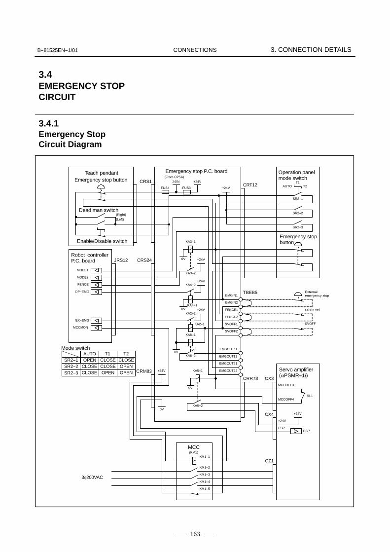
B--81525EN--1/01 3. CONNECTION DETAILSCONNECTIONS
163
CLOSEOPENSR2--1AUTO T1 T2
Dead man switch(Right)(Left)
Enable/Disable switch
SVOFF
Teach pendantEmergency stop button
Emergency stop P.C. board
Robot controllerP.C. board
Operation panelmode switch
Servo amplifier(αPSMR--1i)
Externalemergency stop
CRS1 24INCRT12
+24V
TBEB5EMGIN1
EMGIN2
FENCE1
FENCE2
SVOFF1
EMGOUT11
EMGOUT12
EMGOUT21
EMGOUT22
SVOFF2
JRS12
MODE1
MODE2
+24V0V
CX4 +24V
ESP
+24V
ESP
KA3--1
KA3--2
+24VKA4--2
KA4--10V +24V
KA2--2
KA2--1
KA6--1
KA6--20V
0V
CX3MCCOFF3
MCCOFF4RL1
CZ1
MCC(KM1)
CRS24
KM1--1
KM1--2
KM1--3
KM1--4
KM1--5
CRR78
KA5--2
KA5--1CRM83
0V
+24V
3φ200VAC
FENCE
OP--EMG
EX--EMG
MCCMON
AUTO T2T1
SR2--1
SR2--2
SR2--3
+24V
FUS3FUS4
Emergency stopbutton
(From CP5A)
Mode switch
SR2--2SR2--3 CLOSE
CLOSECLOSEOPEN
CLOSEOPENOPEN
safety net
3.4EMERGENCY STOPCIRCUIT
3.4.1Emergency StopCircuit Diagram

3. CONNECTION DETAILS B--81525EN--1/01CONNECTIONS
164
When the robot is shipped, EMGIN1, and EM-GIN2/SVOFF1 and SVOFF2/FENCE1 and FENCE2are connected by jumper wires. To enable externalemergency stop input, servo off input and fence inputfirst disconnect these jumper wires, then make thenecessary connections.External emergency stop input and fence input arereflected in the external emergency stop output, butservo off input is not reflected in the external emer-gency stop output..In order to prevent any problem caused by a wrongconnection, check the operation of the emergencystop switches on the teach pendant and operatorpanel after connecting the external emergency stopinput, servo off input and fence input.
EMGIN2
EMGIN1
SVOFF2
SVOFF1
EMGIN1EMGIN2SVOFF1SVOFF2
EMGOUT11EMGOUT12EMGOUT21EMGOUT22
TBEB5
Customer should prepare this cable
Cable holder
Emergency stop P.C. boardServo off input
External emergencystop input
FENCE2
FENCE1
Fence input
FENCE2FENCE1
FENCE1FENCE2EMGIN1EMGIN2SVOFF1SVOFF2
3.4.2External EmergencyStop Input
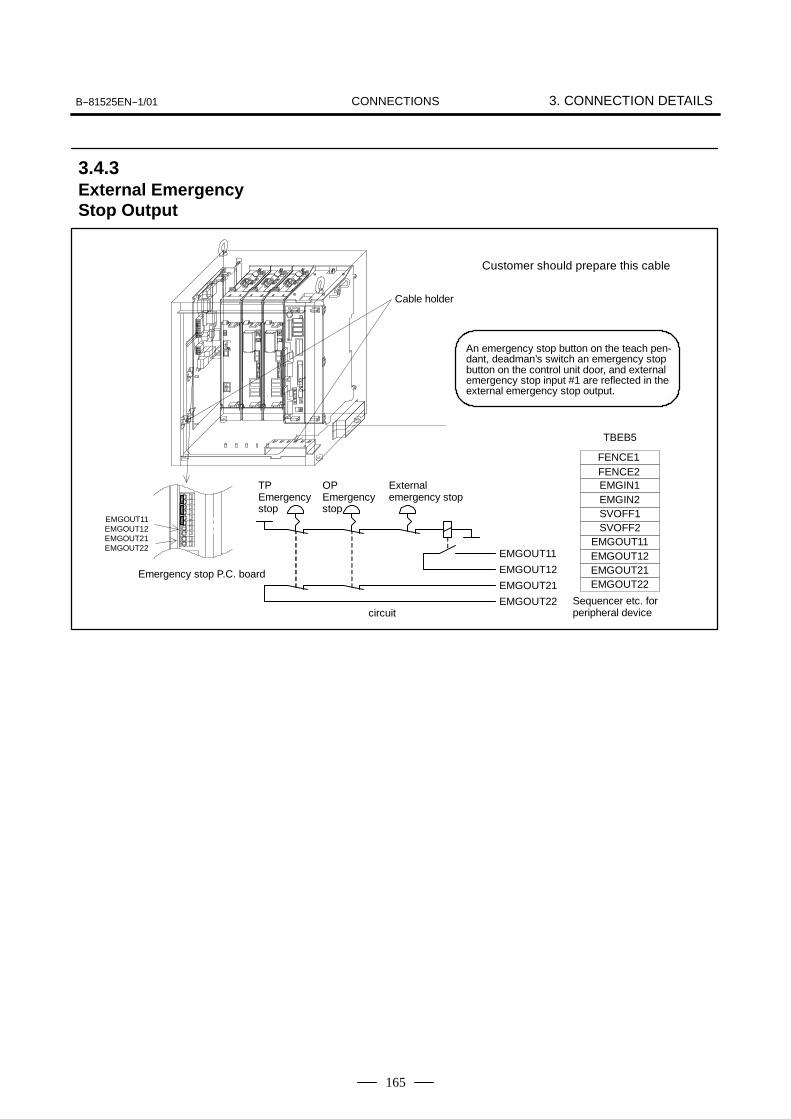
B--81525EN--1/01 3. CONNECTION DETAILSCONNECTIONS
165
EMGIN1EMGIN2SVOFF1SVOFF2
EMGOUT11EMGOUT12EMGOUT21EMGOUT22
TBEB5
Customer should prepare this cable
Cable holder
Emergency stop P.C. board
Externalemergency stop
An emergency stop button on the teach pen-dant, deadman’s switch an emergency stopbutton on the control unit door, and externalemergency stop input #1 are reflected in theexternal emergency stop output.
EMGOUT11
EMGOUT12
EMGOUT21
EMGOUT22
TPEmergencystop
OPEmergencystop
circuitSequencer etc. forperipheral device
FENCE2
EMGOUT11EMGOUT12EMGOUT21EMGOUT22
FENCE1
3.4.3External EmergencyStop Output

3. CONNECTION DETAILS B--81525EN--1/01CONNECTIONS
166
LR Mate 100iB
CXA2A
JF1 (L)
JF2 (M)
CZ2 L
CZ2 M
COP10B COP10A
CXA2B CXA2A
JF1 (L)
JF2 (M)
JF3 (N)
CZ2 L
CZ2 M
CZ2 N
CZ1
CX1A CXA2A
CX3
CX4
COP10B
CXA2B CXA2A
PSM AMP1 AMP2
TB1
L+
L--
TB1
L+
L--
TB1
L+
L--
POWER SUPPLYMODULE
(αPSMR--1i)A06B--6115--H001
SERVO AMPLIFIERMODULE
(αSVM2--20/20i)A06B--6114--H205
SERVO AMPLIFIERMODULE
(αSVM3--10/10/10i)A06B--6114--H302
from MCC
from circuitprotector
from emergencystop P.C.board
from robot controlP.C. board
to robot
Pulse coder
Motor power
LR Mate 200iB
CXA2A
JF1 (L)
JF2 (M)
CZ2 L
CZ2 M
COP10B COP10A
CXA2B CXA2A
JF1 (L)
JF2 (M)
JF3 (N)
CZ2 L
CZ2 M
CZ2 N
CZ1
CX1A CXA2A
CX3
CX4
COP10B
CXA2B CXA2A
PSM AMP1 AMP2
TB1
L+
L--
TB1
L+
L--
TB1
L+
L--
POWER SUPPLYMODULE
(αPSMR--1i)A06B--6115--H001
SERVO AMPLIFIERMODULE
(αSVM3--10/10/10i)A06B--6114--H302
from MCC
from circuitprotector
from emergencystop P.C.board
from robot controlP.C. board
to robot
Pulse coder
Motor power
JF3 (N)
CZ2 N
SERVO AMPLIFIERMODULE
(αSVM3--10/10/10i)A06B--6114--H302
3.5CONNECTION OFSERVO AMPLIFIER
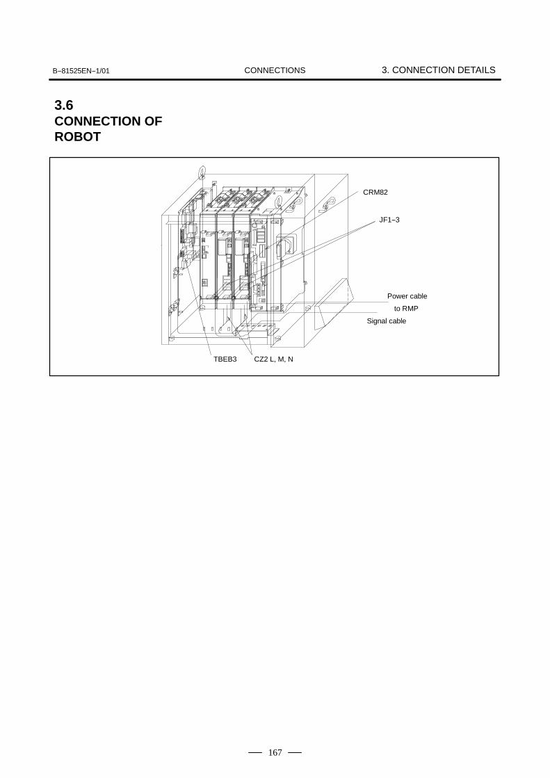
B--81525EN--1/01 3. CONNECTION DETAILSCONNECTIONS
167
CRM82
JF1--3
Power cable
to RMP
Signal cable
CZ2 L, M, NTBEB3
3.6CONNECTION OFROBOT

3. CONNECTION DETAILS B--81525EN--1/01CONNECTIONS
168
Emergency stop unit
CRS1
To teach pendant
Earth plate
Fig.3.7 Teach pendant cable
3.7CONNECTION OFTEACH PENDANTCABLE
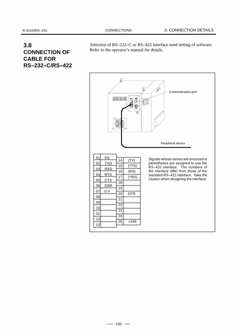
B--81525EN--1/01 3. CONNECTION DETAILSCONNECTIONS
169
Selection of RS--232--C or RS--422 interface need setting of software.Refer to the operator’s manual for details.
Communication port
Peripheral device
01 FG
02 TXD
03 RXD
04 RTS
05 CTS
06 DSR
07 0 V
08
09
10
11
12
13
14 (TX)
15 (*TX)
16 (RX)
17 (*RX)
18
19
20 DTR
21
22
23
24
25 +24E
Signals whose names are enclosed inparentheses are assigned to use theRS--422 interface. The numbers ofthe interface differ from those of thestandard RS--422 interface. Take thecaution when designing the interface.
3.8CONNECTION OFCABLE FORRS--232--C/RS--422
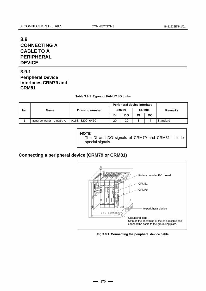
3. CONNECTION DETAILS B--81525EN--1/01CONNECTIONS
170
Table 3.9.1 Types of FANUC I/O Links
Peripheral device interface
No. Name Drawing number CRM79 CRM81 Remarksg
DI DO DI DO
1 Robot controller PC board A A16B--3200--0450 20 20 8 4 Standard
NOTEThe DI and DO signals of CRM79 and CRM81 includespecial signals.
Connecting a peripheral device (CRM79 or CRM81)
Grounding plateStrip off the sheathing of the shield cable andconnect the cable to the grounding plate.
CRM81
to peripheral device
CRM79
Robot controller P.C. board
Fig.3.9.1 Connecting the peripheral device cable
3.9CONNECTING ACABLE TO APERIPHERALDEVICE
3.9.1Peripheral DeviceInterfaces CRM79 andCRM81

B--81525EN--1/01 3. CONNECTION DETAILSCONNECTIONS
171
NOTESee the operator’s MANUAL for the detail information.
Turn off the controller when connecting the cable.
RobotcontrollerPCB
CNC
CRM79
CRM81
CRM79 interface (Specified signals are not allocated and the Robotis connected to CNC and PLC by a FANUC I/O Link cable.)
SDI101
SDI102
SDI103
SDI104
SDI105
SDI106
SDI107
SDI108
SDI109
SDI110
SDI111
SDI112
SDI113
SDI114
SDI115
SDI116
0 V
0 V
SDICOM1
SDICOM2
SDI117
SDI118
SDI119
SDI120
0 V
0 V
+24E
+24E
SDO101
SDO102
SDO103
SDO104
SDO105
SDO106
SDO107
SDO108
SDO109SDO110
SDO111
SDO112
SDO113
SDO114
SDO115
SDO116
+24E
+24E
Connector in cable sideHONDA TSUSHIN CO.,LTDConnector MR--50LMH(Male)
SDICOM1 and SDICOM2 are the signals used for selecting a common for SDI signals.To use the +24V common, connect SDICOM1 and SDICOM2 to 0V.To use the 0V common, connect SDICOM1 and SDICOM2 to +24V.SDICOM1→Selects a common for SDI101 to SDI108.SDICOM2→Selects a common for SDI109 to SDI120.
(Note) Maximum output current per one SDO signal is 70mA.
01
02
03
04
05
06
07
08
09
10
11
12
13
14
15
16
17
18
19
20
21
22
23
24
25
26
27
28
29
30
31
32
33
34
35
36
37
38
39
40
41
42
43
44
45
46
47
48
49
50
SDO120
SDO117
SDO118
SDO119
3.9.2When the Robot isConnected to the CNCby a Peripheral DeviceCable
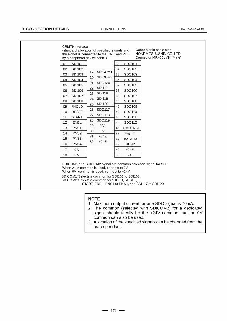
3. CONNECTION DETAILS B--81525EN--1/01CONNECTIONS
172
CRM79 interface(standard allocation of specified signals andthe Robot is connected to the CNC and PLCby a peripheral device cable.)
01 SDI101
02 SDI102
03 SDI103
04 SDI104
05 SDI105
06 SDI106
07 SDI107
08 SDI108
09 *HOLD
10 RESET
11 START
12 ENBL
13 PNS1
14 PNS2
15 PNS3
16 PNS4
17 0 V
18 0 V
19 SDICOM1
20 SDICOM2
21
22 SDI117
23 SDI118
24 SDI119
25 SDI120
26
27
28
29 0 V
30 0 V
31 +24E
32 +24E
33 SDO101
34 SDO102
35 SDO103
36 SDO104
37 SDO105
38 SDO106
39 SDO107
40 SDO108
41 SDO109
42 SDO110
43 SDO111
44 SDO112
45 CMDENBL
46 FAULT
47 BATALM
48 BUSY
49 +24E
50 +24E
Connector in cable sideHONDA TSUUSHIN CO.,LTDConnector MR--50LMH (Male)
SDICOM1 and SDICOM2 signal are common selection signal for SDI.When 24 V common is used, connect to 0V.When 0V common is used, connect to +24VSDICOM1”Selects a common for SDI101 to SDI108.SDICOM2”Selects a common for *HOLD, RESET,
START, ENBL, PNS1 to PNS4, and SDI117 to SDI120.
SDO120
SDO117
SDO118
SDO119
NOTE1 Maximum output current for one SDO signal is 70mA.2 The common (selected with SDICOM2) for a dedicated
signal should ideally be the +24V common, but the 0Vcommon can also be used.
3 Allocation of the specified signals can be changed from theteach pendant.

B--81525EN--1/01 3. CONNECTION DETAILSCONNECTIONS
173
In case +24V common at the peripheral device side. (Specified signals are not allocated)
Control unit (peripheral device interface : CRM79) Peripheral device
SDI101 RVCRM79 (1)
CRM79 (31,32,49,50)
Connector pin No+24E
SDICOM1CRM79 (19)
SDI120CRM79 (25)
SDICOM2CRM79 (20)
CRM79 (17,18,29,30)
0V
SDI102CRM79 (2)
SDI103CRM79 (3)
SDI104CRM79 (4)
SDI105CRM79 (5)
SDI106CRM79 (6)
SDI107CRM79 (7)
SDI108CRM79 (8)
SDI109CRM79 (9)
SDI110CRM79 (10)
SDI111CRM79 (11)
SDI112CRM79 (12)
SDI113CRM79 (13)
SDI114CRM79 (14)
SDI115CRM79 (15)
SDI116CRM79 (16)
SDI117CRM79 (22)
SDI118CRM79 (23)
SDI119CRM79 (24)
3.3kRV
RV
RV
RV
RV
RV
RV
RV
RV
RV
RV
RV
RV
RV
RV
RV
RV
RV
RV
RV
RV
receiver circuit
Fig.3.9.2 (a) Peripheral device control interface : CRM79 (Input signal, +24V common)

3. CONNECTION DETAILS B--81525EN--1/01CONNECTIONS
174
In case 0V common at the peripheral device side. (Specified signals are not allocated)
SDI101 RVCRM79 (1)
SDICOM1CRM79 (19)
SDI120CRM79 (25)
SDICOM2CRM79 (20)
CRM79 (17,18,29,30)
0V
SDI102CRM79 (2)
SDI103CRM79 (3)
SDI104CRM79 (4)
SDI105CRM79 (5)
SDI106CRM79 (6)
SDI107CRM79 (7)
SDI108CRM79 (8)
SDI109CRM79 (9)
SDI110CRM79 (10)
SDI111CRM79 (11)
SDI112CRM79 (12)
SDI113CRM79 (13)
SDI114CRM79 (14)
SDI115CRM79 (15)
SDI116CRM79 (16)
SDI117CRM79 (22)
SDI118CRM79 (23)
SDI119CRM79 (24)
3.3k
Control unit (peripheral device interface : CRM79) Peripheral device
CRM79 (31,32,49,50)
Connector pin No+24E
receiver circuit
RV
RV
RV
RV
RV
RV
RV
RV
RV
RV
RV
RV
RV
RV
RV
RV
RV
RV
RV
RV
RV
Fig.3.9.2 (b) Peripheral device control interface : CRM79 (Input signal, 0V common)

B--81525EN--1/01 3. CONNECTION DETAILSCONNECTIONS
175
(Specified signals are not allocated)
SDO101 DVCRM79 (33)
CRM79 (17,18,29,30)
0V
LOAD
RELAY
SDO102 LOADCRM79 (34)
SDO103CRM79 (35)
SDO104CRM79 (36)
SDO105CRM79 (37)
SDO106CRM79 (38)
SDO107CRM79 (39)
SDO108CRM79 (40)
SDO109CRM79 (41)
SDO110CRM79 (42)
SDO111CRM79 (43)
SDO112CRM79 (44)
SDO113CRM79 (45)
SDO114CRM79 (46)
SDO115CRM79 (47)
SDO116CRM79 (48)
SDO117CRM79 (26)
SDO118CRM79 (27)
SDO119CRM79 (28)
SDO120CRM79 (21)
0V +24V+24V reguratedpower supply
Control unit (peripheral device interface : CRM79) Peripheral device
Connector pin NoDriver circuit
Max. current per SDO is 70mA.
DV
DV
DV
DV
DV
DV
DV
DV
DV
DV
DV
DV
DV
DV
DV
DV
DV
DV
DV
LOAD
LOAD
LOAD
LOAD
LOAD
LOAD
LOAD
LOAD
LOAD
LOAD
LOAD
LOAD
LOAD
LOAD
LOAD
LOAD
LOAD
LOAD
Fig.3.9.2 (c) Peripheral device control interface : CRM79 (Output signal)
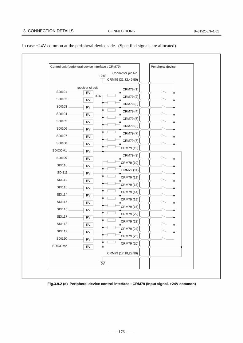
3. CONNECTION DETAILS B--81525EN--1/01CONNECTIONS
176
In case +24V common at the peripheral device side. (Specified signals are allocated)
Control unit (peripheral device interface : CRM79) Peripheral device
SDI101 RVCRM79 (1)
CRM79 (31,32,49,50)
Connector pin No+24E
SDICOM1CRM79 (19)
SDI120CRM79 (25)
SDICOM2CRM79 (20)
CRM79 (17,18,29,30)
0V
SDI102CRM79 (2)
SDI103CRM79 (3)
SDI104CRM79 (4)
SDI105CRM79 (5)
SDI106CRM79 (6)
SDI107CRM79 (7)
SDI108CRM79 (8)
SDI109CRM79 (9)
SDI110CRM79 (10)
SDI111CRM79 (11)
SDI112CRM79 (12)
SDI113CRM79 (13)
SDI114CRM79 (14)
SDI115CRM79 (15)
SDI116CRM79 (16)
SDI117CRM79 (22)
SDI118CRM79 (23)
SDI119CRM79 (24)
3.3kRV
RV
RV
RV
RV
RV
RV
RV
RV
RV
RV
RV
RV
RV
RV
RV
RV
RV
RV
RV
RV
receiver circuit
Fig.3.9.2 (d) Peripheral device control interface : CRM79 (Input signal, +24V common)
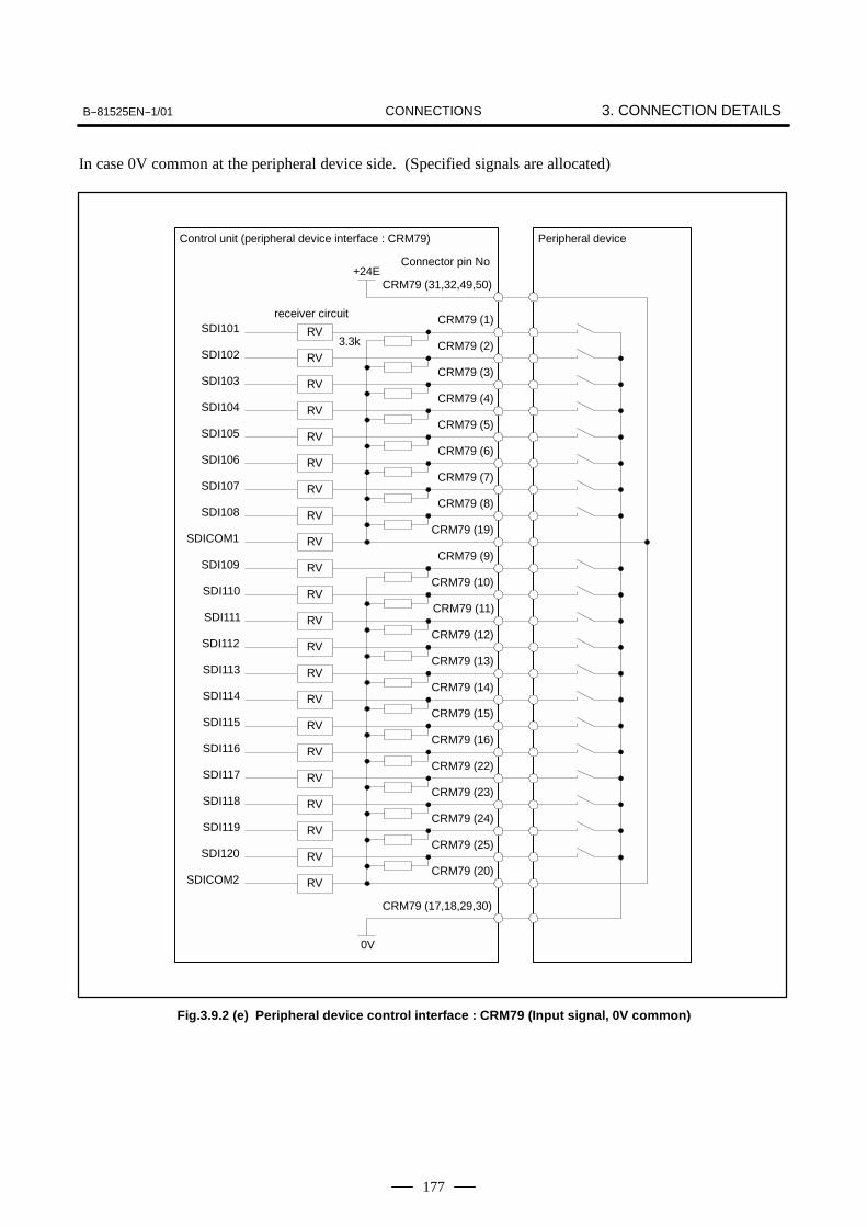
B--81525EN--1/01 3. CONNECTION DETAILSCONNECTIONS
177
In case 0V common at the peripheral device side. (Specified signals are allocated)
SDI101 RVCRM79 (1)
SDICOM1CRM79 (19)
SDI120CRM79 (25)
SDICOM2CRM79 (20)
CRM79 (17,18,29,30)
0V
SDI102CRM79 (2)
SDI103CRM79 (3)
SDI104CRM79 (4)
SDI105CRM79 (5)
SDI106CRM79 (6)
SDI107CRM79 (7)
SDI108CRM79 (8)
SDI109CRM79 (9)
SDI110CRM79 (10)
SDI111CRM79 (11)
SDI112CRM79 (12)
SDI113CRM79 (13)
SDI114CRM79 (14)
SDI115CRM79 (15)
SDI116CRM79 (16)
SDI117CRM79 (22)
SDI118CRM79 (23)
SDI119CRM79 (24)
3.3k
Control unit (peripheral device interface : CRM79) Peripheral device
CRM79 (31,32,49,50)
Connector pin No+24E
receiver circuit
RV
RV
RV
RV
RV
RV
RV
RV
RV
RV
RV
RV
RV
RV
RV
RV
RV
RV
RV
RV
RV
Fig.3.9.2 (e) Peripheral device control interface : CRM79 (Input signal, 0V common)

3. CONNECTION DETAILS B--81525EN--1/01CONNECTIONS
178
(Specified signals are allocated)
SDO101 DVCRM79 (33)
CRM79 (17,18,29,30)
0V
LOAD
RELAY
SDO102 LOADCRM79 (34)
SDO103CRM79 (35)
SDO104CRM79 (36)
SDO105CRM79 (37)
SDO106CRM79 (38)
SDO107CRM79 (39)
SDO108CRM79 (40)
SDO109CRM79 (41)
SDO110CRM79 (42)
SDO111CRM79 (43)
SDO112CRM79 (44)
SDO113CRM79 (45)
SDO114CRM79 (46)
SDO115CRM79 (47)
SDO116CRM79 (48)
SDO117CRM79 (26)
SDO118CRM79 (27)
SDO119CRM79 (28)
SDO120CRM79 (21)
0V +24V+24V reguratedpower supply
Control unit (peripheral device interface : CRM79) Peripheral device
Connector pin NoDriver circuit
Max. current per SDO is 70mA.
DV
DV
DV
DV
DV
DV
DV
DV
DV
DV
DV
DV
DV
DV
DV
DV
DV
DV
DV
LOAD
LOAD
LOAD
LOAD
LOAD
LOAD
LOAD
LOAD
LOAD
LOAD
LOAD
LOAD
LOAD
LOAD
LOAD
LOAD
LOAD
LOAD
Fig.3.9.2 (f) Peripheral device control interface : CRM79 (Output signal)
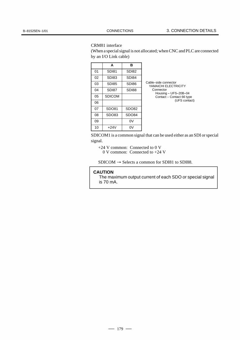
B--81525EN--1/01 3. CONNECTION DETAILSCONNECTIONS
179
CRM81 interface(When a special signal is not allocated; when CNC andPLC areconnectedby an I/O Link cable)
A B
01 SDI81 SDI82
02 SDI83 SDI84
03 SDI85 SDI86
04 SDI87 SDI88
05 SDICOM
06
07 SDO81 SDO82
08 SDO83 SDO84
09 0V
10 +24V 0V
SDICOM1 is a common signal that can be used either as an SDI or specialsignal.
+24 V common: Connected to 0 V0 V common: Connected to +24 V
SDICOM → Selects a common for SDI81 to SDI88.
CAUTIONThe maximum output current of each SDO or special signalis 70 mA.
Cable--side connectorYAMAICHI ELECTRICITY
ConnectorHousing -- UFS--20B--04Contact -- Contact 66 type
(UFS contact)
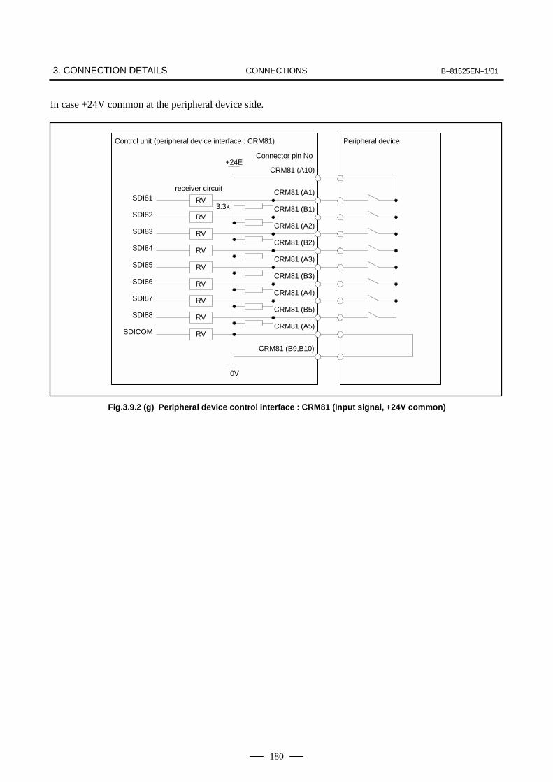
3. CONNECTION DETAILS B--81525EN--1/01CONNECTIONS
180
In case +24V common at the peripheral device side.
SDI81CRM81 (A1)
CRM81 (A10)
SDICOMCRM81 (A5)
SDI88CRM81 (B5)
CRM81 (B9,B10)
0V
SDI82CRM81 (B1)
SDI83CRM81 (A2)
SDI84CRM81 (B2)
SDI85CRM81 (A3)
SDI86CRM81 (B3)
SDI87CRM81 (A4)
Control unit (peripheral device interface : CRM81) Peripheral device
Connector pin No+24E
RV3.3k
receiver circuit
RV
RV
RV
RV
RV
RV
RV
RV
Fig.3.9.2 (g) Peripheral device control interface : CRM81 (Input signal, +24V common)

B--81525EN--1/01 3. CONNECTION DETAILSCONNECTIONS
181
In case 0V common at the peripheral device side.
SDI81CRM81 (A1)
CRM81 (A10)
SDICOMCRM81 (A5)
SDI88CRM81 (B5)
CRM81 (B9,B10)
0V
SDI82CRM81 (B1)
SDI83CRM81 (A2)
SDI84CRM81 (B2)
SDI85CRM81 (A3)
SDI86CRM81 (B3)
SDI87CRM81 (A4)
Control unit (peripheral device interface : CRM81) Peripheral device
Connector pin No+24E
receiver circuit
RV3.3k
RV
RV
RV
RV
RV
RV
RV
RV
Fig.3.9.2 (h) Peripheral device control interface : CRM81 (Input signal, 0V common)
SDO81
CRM81 (A7)
CRM81 (B9,B10)
SDO82 LOADCRM81 (B7)
SDO83CRM81 (A8)
SDO84CRM81 (B8)
0V +24V
DVRELAY
Control unit (peripheral device interface : CRM81) Peripheral device
Connector pin NoDriver circuit LOAD
DV
DV
DV
LOAD
LOAD
0V
+24V reguratedpower supply
Max. current per SDO is 70mA.
Fig.3.9.2 (i) Peripheral device control interface : CRM81 (Output signal)

3. CONNECTION DETAILS B--81525EN--1/01CONNECTIONS
182
This section describes the specifications of the digital I/O signalsinterfaced with the peripheral device and end effector.
Connection example
Protective resistance
Lamp
70 mAor less
0V
+24V
70 mAor less
0V
+24V
Spark killer diode
0V
0V
D Electrical specificationsRated voltage : 24 VDCMaximum applied voltage : 30 VDCMaximum load current : 70.mATransistor type : Open collector NPNSaturation voltage at connection : 1.0 V (approx.)
D Spark killer diodeRated peak reverse voltage : 100 V or moreRated effective forward current : 1 A or more
D Notes on useDo not use the +24 V power supply of the robot.When loading a relay, solenoid, and so on directly, connect them inparallel with diodes for preventing back electromotive force.If a load causing a surge current such as turning on LED is connected,use a protective resistance.
D Applicable signalOutput signal of peripheral device interface CRM79, CRM81 :
SDO101 to SDO120 (CRM79)SDO81 to SDO84 (CRM81)
3.9.3Digital I/O SignalSpecifications
3.9.3.1Peripheral deviceinterface CRM 79 andCRM 81
D Output signal regulation

B--81525EN--1/01 3. CONNECTION DETAILSCONNECTIONS
183
Connection example
3.3 kΩ
RV
SDICOM
+24V
0V
RV
SDI n
Example of+24V common connection
D Electrical specifications of the receiverType : Grounded voltage receiverRated input voltage : Contact close :+20 V to +28 V
Contact open :0 V to +4 VMaximum applied input voltage: +28 VDCInput impedance : 3.3 kΩ (approx.)Response time : 5 ms to 20 ms
D Specifications of the peripheral device contactRated contact capacity : 30 VDC, 50 mA or moreInput signal width : 200 ms or more (on/off)Chattering time : 5 ms or lessClosed circuit resistance : 100Ω or lessOpened circuit resistance : 100 kΩ or more
(Signal)(Signal)
TCTC
TBTBTB
Peripheral devicecontact signal
Robot receiver signal
TB ; Chattering 5 ms or lessTC ; 5 to 20 ms
D Note on useApply the +24 V power of the robot to the receiver.However, the above signal regulations must be satisfied at therobot receiver.
D Applicable signalInput signal of peripheral device interface CRM79, CRM81 :
SDO101 to SDO120 (CRM79)SDO81 to SDO84 (CRM81)
D Input signal regulation

3. CONNECTION DETAILS B--81525EN--1/01CONNECTIONS
184
The figure below shows the connector for peripheral device cable.
Symbol Name
1 Connector cover
2 Cable clamp screw
3 Connector clamp spring
4 Connector clamp screw
5 Connector 50 pins (male) MR50MH
Connector Applicable Dimensions RemarkConnectorspecification
Applicableinterface A (B) C (D) Honda Tsushin
MR50LMH CRM79 67.9 73.5 44.8 18Honda TsushinKogyo 50 pins
Fig.3.9.4 (a) Peripheral Device Cable Connector (CRM79 : Honda Tsushin Kogyo)
3.9.4Peripheral DeviceCable Connector

B--81525EN--1/01 3. CONNECTION DETAILSCONNECTIONS
185
Connector Applicable DimensionsRemarkConnector
specificationApplicable
interface A CRemark
UFS--20B--04
CRM81
29.98 22.86 YAMAICHI ELECTRONICS(Housing)
Contact 66 typeCRM81
YAMAICHI ELECTRONICS(Contact)
Applicable cable : AWG#28 (7/0.12), AWG#26 (19/0.1), AWG#24 (19/0.12), (7/0.18)
Fig.3.9.4 (b) Peripheral Device Cable Connector (CRM81 : YAMAICHI ELECTRONICS)
Connect a peripheral device using a completely shielded, heavilyprotected cable conforming to the specifications in Table 3.9.5.Allow an extra 1.5m for routing the cable in the control unit.The maximum cable length is 30m.
Table 3.9.5 Recommended cable (For peripheral device connection)
Wire specificationsConductor
SheathEffective Electrical characteristics
Number ofwires
Wire specifications(FANUC
specifications)Diameter
(mm)Configura-
tion
Sheaththickness
(mm)
Effectiveoutside
diameter(mm)
Conductorresistance
(Ω/km)
Allowablecurrent (A)
50 A66L--0001--0042 φ1.05 7/0.18AWG24
1.5 φ12.5 106 1.6
20 A66L--0001--0041 φ1.05 7/0.18AWG24
1.5 φ10.5 106 1.6
3.9.5Recommended Cables
3.562.54
AB
2.54
6.0
14.314.5

3. CONNECTION DETAILS B--81525EN--1/01CONNECTIONS
186
Table 3.10.1 Types of end effector interfaces
No Name Drawing numberEnd effector interface
RemarksNo. Name Drawing numberDI DO
Remarks
1 Robot controller PC board A A16B--3200--0450 6 6 Standard
NOTEEither RDI6 or *PPABN is selected in the software.
1 RDI1 7 *HBK2 RDI2 8 +24E3 RDI3 9 +24E4 RDI4 10 +24E5 RDI5 11 0V
6 RDI6(*PPABN)
12 RDICOM
EE
Mechanical unit
End effecter
NOTERDO1 to RDO6 are used as the signals to turn on or offsolenoid valves. The end effector can use the RDI signalsand *HBK signal. For RDO signals, refer to themaintenance manual of the mechanical unit.
3.10END EFFECTORINTERFACE
3.10.1Connecting theMechanical Unit andEnd Effector

B--81525EN--1/01 3. CONNECTION DETAILSCONNECTIONS
187
End effector
RDI1 RVEE (1)
EE (8,8,10)Connector pin No.+24E
Receiver circuit
RDICOMEE (12)
EE (11)
0V
RDI2EE (2)
RDI3EE (3)
RDI4EE (4)
RDI5EE (5)
RDI6(*PPABN)
EE (6)
3.3k
Mechanical unit (end effector interface)
RV
RV
RV
RV
RV
RV
Fig.3.10.1 (a) End effector interface (+24V common)
End effector
RDI1 RVEE (1)
EE (8,8,10)Connector pin No.+24E
Receiver circuit
RDICOMEE (12)
EE (11)
0V
RDI2EE (2)
RDI3EE (3)
RDI4EE (4)
RDI5EE (5)
RDI6(*PPABN)
EE (6)
3.3k
Mechanical unit (end effector interface)
RV
RV
RV
RV
RV
RV
Fig.3.10.1 (b) End effector interface (0V common)

3. CONNECTION DETAILS B--81525EN--1/01CONNECTIONS
188
Connection example
3.3 kΩ
RV
RDICOM
+24V
0V
RV
RDI n
+24V commonconnection example
Electrical specifications of the receiver
Type : Grounded voltage receiverRated input voltage : Contact close
: +20 V to +28 VContact open
: 0 V to +4 VMaximum applied input voltage : +28 VDCInput impedance : 3.3 kΩ (approx.)Response time : 5 ms to 20 ms
Specifications of the peripheral device contact
Rated contact capacity : 30 VDC, 50 mA or moreInput signal width : 200 ms or more (on/off)Chattering time : 5 ms or lessClosed circuit resistance : 100 Ω or lessOpened circuit resistance : 100 kΩ or more
(Signal)(Signal)
TCTC
TBTBTB
Peripheral devicecontact signal
Robot receiver signalTB ; Chattering 5 ms or lessTC ; 5 to 20 ms
Note on use
Apply the +24 V power at the robot to the receiver.However, the above signal specifications must be satisfied at therobot receiver.
Applicable signals
Input signals of end effecter control interfaceAdditional I/O PCB CRW6 input signal WDI1 to WDI8RDI 1 to 6, *HBK, *PPABN (Switch RDI6 by software)
3.10.2Digital I/O SignalSpecifications of EndEffecter ControlInterface

B--81525EN--1/01 3. CONNECTION DETAILSCONNECTIONS
189
In this manual the treatment for the shielded cable is shown on severalpages. Partly cut off the shielded cable to expose the shield jacket, andfasten the jacket to the shield plate with a clamp to protect against noise.(In case of stand--alone type a shield plate is installed in the controller.)
Fig.3.11 Shielded cable treatment
3.11TREATMENT FORTHE SHIELDEDCABLE

CONNECTION4. TRANSPORTATION AND
INSTALLATION B--81525EN--1/01
190
4 TRANSPORTATION AND INSTALLATION

CONNECTIONB--81525EN--1/014. TRANSPORTATION AND
INSTALLATION
191
The control unit should be transported by a crane. Attach a sling to eyebolts at the top of the control unit.
Fig.4.1 Transportation
Installation areaWhen the control unit is installed, allow the space for maintenance shownin the following figure.
When the pluralcontroller isinstalled.
Control unit Control unitControl unit
Fig.4.2 Installation
4.1TRANSPORTATION
4.2INSTALLATION

CONNECTION4. TRANSPORTATION AND
INSTALLATION B--81525EN--1/01
192
Four M10 weld nuts (4 pcs)The unit is shipped with the M10 boltsscrewed to the weld nuts as 10--mm feet.After the M10 bolts are removed, theseweld nuts can be used to secure thecontrol unit.
Fig.4.3 External drawing of robot controller
4.3EXTERNALCONTROLLERDIMENSIONS

CONNECTIONB--81525EN--1/014. TRANSPORTATION AND
INSTALLATION
193
Item Specifications/condition
Transformer 50Hz/60Hz;220/380/415/440/500VAC,+10%, --15%
50/60Hz ± 1Hz, 3--phase
Input power supply capacity 1 kVA (LR Mate 100iB)1.2 kVA (LR Mate 200iB)
Average power consumption 0.4 kW (LR Mate 100iB)0.5 kW (LR Mate 200iB)
Permissible ambient temper-ature
0 to 45_C during operation, and --20 to 60 Cduring shipment and storage with a tempera-ture coefficient of 1.1_C/min.
Permissible ambient humid-ity
Relative humidity: 30% to 95%, non--condens-ing.
Surrounding gas An additional protective provision is neces-sary if the machine is installed in an environ-ment in which there are relatively largeamounts of contaminants (dust, dielectricfluid, organic solvent, acid, corrosive gas,and/or salt).
Vibration 0.5 G or less. When using the robot in a loca-tion subject to serious vibration, consult withyour FANUC sales representative.
Altitude Not higher than 1,000 m above sea level
Ionized and nonionized radi-ations
A shielding provision is necessary if themachine is installed in an environment inwhich it is exposed to radiations (microwave,ultraviolet rays, laser beams, and/or X--rays).
Weight of control unit Approx. 55kg
Adjust and check according to following procedure at installation.
No. Description
1 Visually check the inside and outside of the control unit.
2 Check if the screwed terminal is connected properly.
3 Check that the connectors and printed circuit boards are inserted cor-rectly.
4 Connect control unit and mechanical unit cables.
5 Turn the breaker off and connect the input power cable.
6 Check the input power voltagage.
7 Press the EMERGENCY STOP button on the operator’s panel andturn the power on. Check the output voltage.
8 Check the interface signals between control unit and robot mechanicalunit.
9 Check the parameters. If necessary, set them.
10 Release the EMERGENCY STOP button on the operator’s panel.Turn the power on.
11 Check the movement along each axis in the manual jog mode.
12 Check the end effector interface signals.
13 Check the peripheral device control interface signals.
4.4INSTALLATIONCONDITION
4.5ADJUSTMENT ANDCHECKS ATINSTALLATION

CONNECTION4. TRANSPORTATION AND
INSTALLATION B--81525EN--1/01
194
An overtravel and emergency stop occur when the robot is operated forthe first time after it is installed and the mechanical and control units arewired. This section describes how to reset the overtrvel and emergencystop.Remove the red plate fastening the swiveling axis beforehand.The J2 and J3 axes are pressed against the hard stops at shipment.Therefore, an overtravel alarm occurs when the power is turned on afterinstallation.
(1) Press the [MENUS] key on the teach pendant.
(2) Select [Next].
(3) Select [SETUP].
(4) Press F1 [TYPE].
(5) Select [Config] to disable or enable Hand Break.
Hand break
State Hand break HBK (*1) HBK detection Robot operation Message
1 Enabled CLOSE Detected Possible Not provided
2 Enabled OPEN Detected Impossible SERVO 6
3 Disabled CLOSE Detected (*2) Possible Not provided
4 Disabled OPEN Not detected Possible SERVO 300 at cold start
NOTE1 Robot end effector connector
2 When the HBK circuit is closed, the HBK detection isenabled.If the HBK state changes from close to open, the SERVO300 or SERVO 302 alarm occurs, stopping the robot.
3 If the power is turned off and on in the state describedabove, the system enters state 4, releasing the alarm.
CLOSE OPEN24V
*HBK
24V
*HBK
4.6NOTE ATINSTALLATION
4.7DISABLING HANDBREAK

APPENDIX

B--81525EN--1/01 A. TOTAL CONNECTION DIAGRAMAPPENDIX
197
A TOTAL CONNECTION DIAGRAM

A. TOTAL CONNECTION DIAGRAM B--81525EN--1/01APPENDIX
198
Fig.A (a) Total connection diagram

B--81525EN--1/01 A. TOTAL CONNECTION DIAGRAMAPPENDIX
199
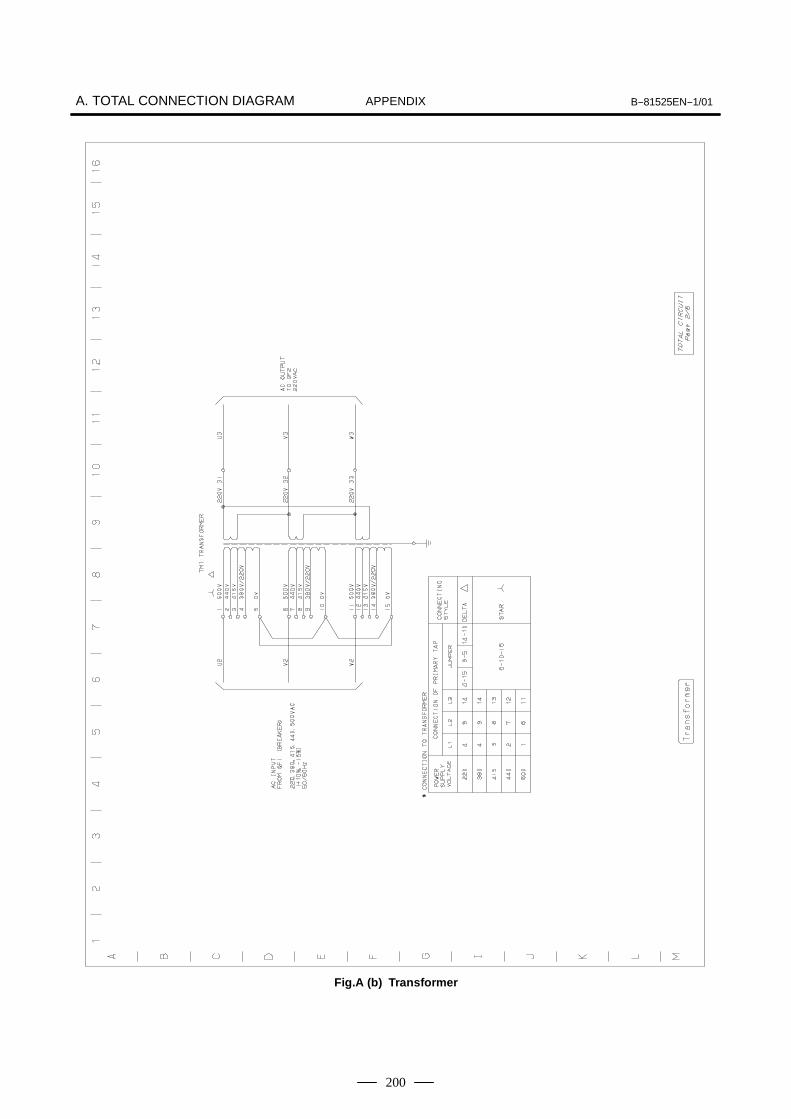
A. TOTAL CONNECTION DIAGRAM B--81525EN--1/01APPENDIX
200
Fig.A (b) Transformer

B--81525EN--1/01 A. TOTAL CONNECTION DIAGRAMAPPENDIX
201

A. TOTAL CONNECTION DIAGRAM B--81525EN--1/01APPENDIX
202
Fig.A (c) Emergency stop circuit diagram (LR Mate 100iB)
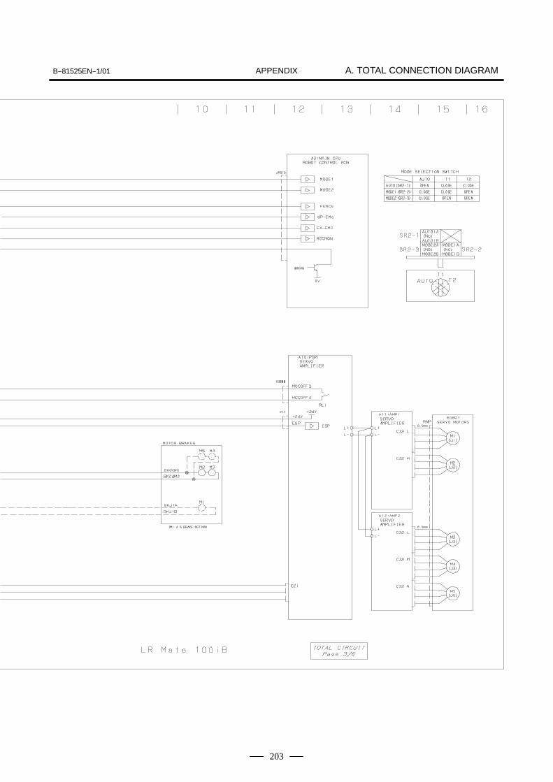
B--81525EN--1/01 A. TOTAL CONNECTION DIAGRAMAPPENDIX
203

A. TOTAL CONNECTION DIAGRAM B--81525EN--1/01APPENDIX
204
Fig.A (d) Emergency stop circuit diagram (LR Mate 200iB)

B--81525EN--1/01 A. TOTAL CONNECTION DIAGRAMAPPENDIX
205

A. TOTAL CONNECTION DIAGRAM B--81525EN--1/01APPENDIX
206
Fig.A (e) Robot controller P.C. board, emergency stop P.C. board connector interface
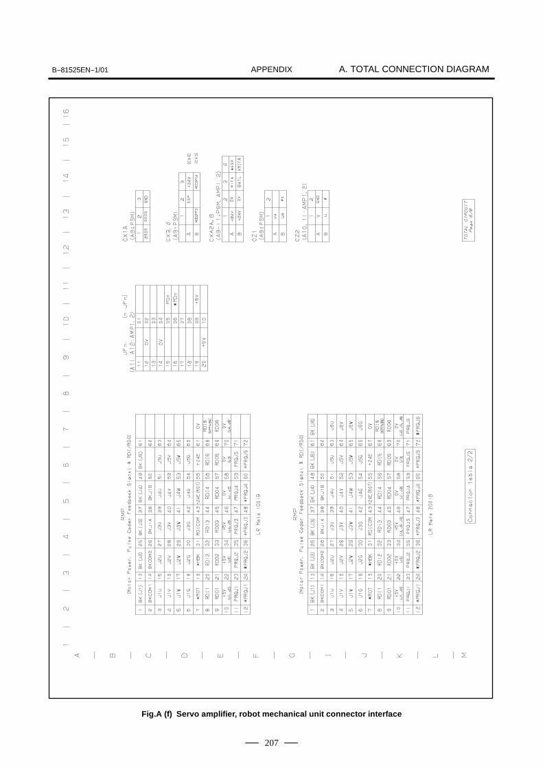
B--81525EN--1/01 A. TOTAL CONNECTION DIAGRAMAPPENDIX
207
Fig.A (f) Servo amplifier, robot mechanical unit connector interface
B--81525EN--1/01APPENDIXB. PERIPHERAL INTERFACE
208
B PERIPHERAL INTERFACE
Peripheral I/O (UI/UO) are a group of specialized signals whose usage isdecided by the system. These signals are connected with a remotecontroller and the peripheral devices via the following interfaces and I/Olinks and they are used to control the robot from the outside.
D The JD1A interface (The process I/O PC board, the I/O Unit MODELA and the MODEL B are connected as the slave of I/O link to R--J3iBMate.) (on master mode)
D The JD1B interface (CNC and PLC are connected as a master of I/Olink to R--J3iB Mate.) (on slave mode)
D CRM9 interfaceRefer to the operator’s MANUAL for detail informations.

B--81525EN--1/01 APPENDIX B. PERIPHERAL INTERFACE
209
The tables below list the special signals of the R--J3iB Mate robotcontroller.
Input signals (See Subsection B.2.1.)
Signal Description
*HOLDRESETSTARTENBLPNS1PNS2PNS3PNS4
Temporary stopAlarm releaseCycle startEnableProgram select (*1)Program select (*1)Program select (*1)Program select (*1)
NOTEPNS (program select input) (optional)
Output signals (See Subsection B.2.1.)
Signal Description
CMDENBLFAULTBATALMBUSY
Input acceptableAlarmBattery alarmBusy
B.1SIGNAL TYPES
B--81525EN--1/01APPENDIXB. PERIPHERAL INTERFACE
210
Fellowing is each input signal.
The remote controller uses the hold signal to halt the robot. Because*HOLD input signal is a inverted signal, normally set the signal on. Whenthe signal goes off, the following is executed:
D The robot is decelerated until its stops, then the program execution ishalted.
D If ENABLED is specified at “Break on hold” on the general itemsetting screen, the robot is stopped, an alarm is generated, and theservo power is turned off. (Standard setting: DISABLED)
The RESET signal cancels an alarm. If the servo power is off, the RESETsignal turns on the servo power. The alarm output is not canceled until theservo power is turned on. The alarm is canceled at the instant this signalfalls in default setting.
D If TRUE is specified at “CSTOPI for ABORT” on the systemconfiguration screen, the RESET signal resets an alarm and aborts thecurrently selected program. (Standard setting: FALSE)
D To have alarms reset the instant the RESET signal rises, it is necessaryto specify RISE at “Detect FAULT RESET signal” on the systemconfiguration screen. (Standard setting: FALL)
The START signal has two functions. It can select or collate a programand start the program.
D When the START signal goes high, PNS1 to PNS4 are read and thecorresponding program is selected or collated. Whether is program isselected or collated is specified by the setting of system variable$SHELL_CFG.$NUM_RSR [1]. (See the description of signalsPNS1 to PNS4.)
D When the START signal goes low, the current program is started fromthe line at which the cursor is placed (current line).
D If TRUE is specified at “START for CONTINUE only” on the systemconfiguration screen, only a program on hold can be started. (Standardsetting: FALSE)
The ENBL signal allows the robot to be moved and places the robot in theready state. When the ENBL signal is off, the system inhibits a jog feedof the robot and activation of a program including a motion (group). Aprogram which is being executed is halted when the ENBL signal is setoff.
NOTEWhen the ENBL signal is not monitored, strap the signalwith the ground.
B.2I/O SIGNALS
B.2.1Input Signals
Hold input signals,*HOLD, UI [ 1 ]
Fault reset input signal,RESET, UI [ 2 ]
Start input signal,START, UI [ 3 ] (validatedin the remote state)
Enable input signal,ENBL, UI [ 4 ]

B--81525EN--1/01 APPENDIX B. PERIPHERAL INTERFACE
211
A program number selection signal has two functions.When the START signal goes on, PNS1 to PNS4 are read and thecorresponding program is selected or collated. Whether the program isselected or collated is specified by the setting of system variable$SHELL_CFG.$NUM_RSR [1].
D In the program end state, a program is selected or collated accordingto the state (0 or 1) of the PNS signals. The current line of the selectedor collated program is set to 1.
- Type 1 (when $SHELL_CFG.$NUM_RSR [1] is set to 0)The program specified by the PNS signals is selected.
- Type 2 (when $SHELL_CFG.$NUM_RSR [1] is set to 1)The program specified by the PNS signals is collated with thecurrent program. If the programs do not agree with each other, anerror occurs.
D If all PNS signals are low in the program end state, the current programis executed from the current line. If no programs are selected, an erroroccurs.
D A halted program can be resumed only when all PNS signals are setoff. Otherwise, an error occurs.
D While a program is being executed, the PNS signals are ignored.
Fellowing are peripheral device interface output signals.
The CMDENBL signal is output when the following conditions aresatisfied. The CMDENBL signal indicates that the remote controller canstart a program including a motion (group).
D The remote conditions are satisfied.D The ready conditions are satisfied.
D The continuous operation mode is selected (the single step mode isdisabled).
The FAULT signal is output when an alarm occurs in the system. TheRESET signal cancels the alarm. If a warning (WARN alarm) occurs, theFAULT signal is not output.
The BATALM signal indicates that the voltage of the battery forsupporting the memory has dropped. Replace the battery while keepingthe power of the controller on.
To have the BATALM signal generated also when the BZAL/BLALalarmoccurs, it is necessary to set the $BLAL_OUT.$BATALM_OR systemvariable. It is also possible to have the specified SDO output when theBZAL/BLAL alarm occurs.
The BUSY signal is output while a program is being executed. The BUSYsignal is not output while a program is being halted.
Program numberselection signals, PNS1to PNS4, UI [ 5 to 8 ](validated in the remotestate)
B.2.2Output signals
Command enable outputsignal, CMDENBL,UO [ 1 ]
Fault output signal,FAULT, UO [ 2 ]
Battery alarm outputsignal, BATALM, UO [ 3 ]
Busy output signal,BUSY, UO [ 4 ]

B--81525EN--1/01APPENDIXB. PERIPHERAL INTERFACE
212
This section describes the external specifications of digital and analoginput/output in the R--J3iB Mate controller.
The R--J3iB Mate controller can use up to 512 digital input and outputpoints or an equivalent number of analog input and output points. Oneanalog input/output point uses the resources equivalent to those used by16 digital I/O points. The R--J3iB Mate can use a total of up to 512 I/Opoints.
The R--J3iB Mate controller can use the following I/O hardware.- Process I/O printed circuit board- I/O unit model A
The process I/O printed circuit board and the I/O unit model A can be usedtogether.
B.3SPECIFICATIONS OFDIGITALINPUT/OUTPUT
B.3.1Overview
B.3.2Input/Output HardwareUsable in the R-J3iBMate Controller

B--81525EN--1/01 APPENDIX B. PERIPHERAL INTERFACE
213
(1) RDI/RDOThese are signals sent to the connector at the wrist of the robot.They cannot be assigned (redefined) and are fixed.The standard format is six inputs and six outputs. The number ofpoints that can be used for the connector at the wrist depends on theindividual robot.
(2) SDI/SDOThe signal No. that is determined at hardware can be changed bysoftware operation.
(3) Analog I/OAn analog I/O signal can access the analog I/O port (optional) on theprocess I/O printed circuit board or the I/O port on the analog I/Omodule (used together with the I/O unit model A).It reads and writes the digital value converted from the analog valueof the I/O voltage. It means that the value does not always representthe real I/O voltage.
(4) Group I/OGroup I/O is a function which can input or output multiple DI/DOsignals as binary codes.Any number of continuous signals of up to 16 bits can be set for itsuse.It can be set in the menu DETAILS on the group I/O screen.
B.3.3SoftwareSpecifications
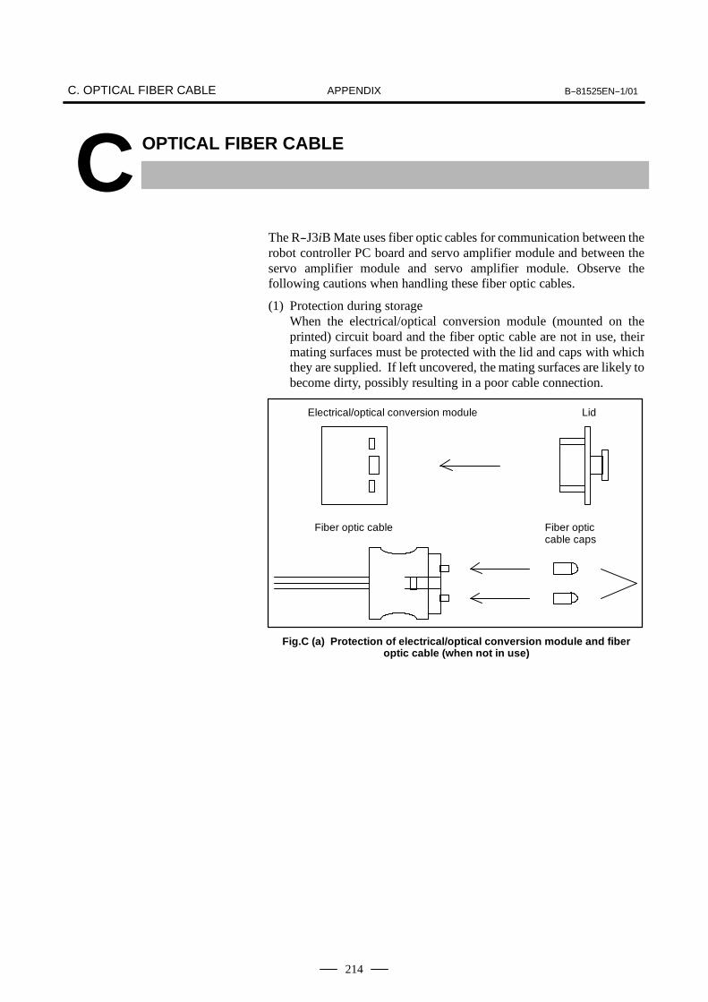
C. OPTICAL FIBER CABLE B--81525EN--1/01APPENDIX
214
C OPTICAL FIBER CABLE
The R--J3iB Mate uses fiber optic cables for communication between therobot controller PC board and servo amplifier module and between theservo amplifier module and servo amplifier module. Observe thefollowing cautions when handling these fiber optic cables.
(1) Protection during storageWhen the electrical/optical conversion module (mounted on theprinted) circuit board and the fiber optic cable are not in use, theirmating surfaces must be protected with the lid and caps with whichthey are supplied. If left uncovered, the mating surfaces are likely tobecome dirty, possibly resulting in a poor cable connection.
Electrical/optical conversion module Lid
Fiber optic cable Fiber opticcable caps
Fig.C (a) Protection of electrical/optical conversion module and fiberoptic cable (when not in use)

B--81525EN--1/01 C. OPTICAL FIBER CABLEAPPENDIX
215
(2) Fiber optic cableD Grasp the optical connector firmly when connecting or
disconnecting the cable. Do not pull on the fiber optic cord itself.(The maximum tensile strength between the fiber cord andconnector is 2 kg. Applying greater force to the cord is likely tocause the connector to come off, making the cable unusable.)Fiber optic cord diameter : 2.2 mm × 2 cordsTensile strength : Fiber optic cord :7 kg per cord
Between fiber optic cord and connector : 2 kgMinimum bending radius of fiber optic cord :25 mmFlame resistance : Equivalent to UL VW--1Operating temperature : --20 to 70°C
60 max.
8.2
21
6.7 19 max. 35typ.
Code Bush Reinforced cover
Fig.C (b) External dimensions of external optical cable Unit : mm
D Afler it is connected, the optical connector is automatically lockedby the lock levers on its top. To remove the connector, release thelock levers and pull the connector.
D Although optical connectors cannot be connected in other than thecorrect orientation, always take note of the connector’s orientationbefore making the connection.
D Take care to keep both parts of the optical connector (cable side andPCB side) clean. If they become dirty, wipe them with tissue paperor absorbent cotton to remove dirt. The tissue paper or absorbentcotton may be moistened with ethyl alcohol. Do not use anyorganic solvent other than ethyl alcohol.
D Do not clamp the uncovered portion of the cable with a nylon band.

IndexB--81525EN--1/01
i--1
[A]Adjustment and Checks at Installation, 193
Alarm Occurrence Screen, 30
[B]Backplane PC Board (A20B--2003--0330), 116
Battery for Memory Backup (3 VDC), 151
Block Diagram, 156
Block Diagrams of the Power Supply, 123
[C]Checking the Power Supply Module, 124
Checking the Power Supply Unit, 124
Circuit Diagram of Emergency Stop, 163
Component Functions, 24
Configuration, 20
Connecting a Cable to a Peripheral Device, 170
Connecting the Mechanical Unit and End Effector,186
Connection Details, 157
Connection of Cable for RS--232--C/RS--422, 169
Connection of I/O Link Cable, 161
Connection of Power Supply Cable, 158
Connection of Robot, 167
Connection of Teach Pendant Cable, 168
Coonection of Servo Amplifier, 166
[D]Digital I/O Signal Specifications, 182
Digital I/O Signal Specifications of End Effecter Con-trol Interface, 188
Disabling Hand Break, 194
[E]Emergency Stop Circuit, 163
Emergency Stop PC Board (A20B--1008--0022,--0023), 115
End Effector Interface, 186
External Controller Dimensions, 192
External Emergency Stop Input, 164
External Emergency Stop Output, 165
External View of the Controller, 21
[F]FANUC I/O Link, 159
[I]I/O Signals, 210
Initial Screen Remains on the Teach Pendant, 29
Input Signals, 210
Input/Output Hardware Usable in the R--J3iB MateController, 212
Installation, 191
Installation Condition, 193
[L]LED of Power Supply Module, 120
LED of Servo Amplifier, 120
LED of Servo Amplifier Module, 121
[M]Manual Operation Impossible, 108
Mastering, 34
[N]Note at Installation, 194
[O]Operator Safety, 4, 6
Optical Fiber Cable, 214
Outline Drawings, 118
Output signals, 211
[P]Peripheral Device Cable Connector, 184
Peripheral device interface CRM 79 and CRM 81, 182
Peripheral Device Interfaces CRM79 and CRM81,170

Index B--81525EN--1/01
i--2
Peripheral interface, 208
Position Deviation Found in Return to the ReferencePosition (Positioning), 106
Power Cannot be Turned On, 27
Power Supply Module PSM (A06B--6115--H001), 118
Precautions for Mechanism, 10
Precautions for Mechanisms, 11
Precautions in Operation, 11
Precautions in Programming, 10, 11, 12
Preventive Maintenance, 25
Printed Circuit Boards, 110
[R]Recommended Cables, 185
Replacing a Fuse, 146
Replacing a Fuse on the Emergency Stop PC Board,147
Replacing a Fuse on the Robot Controller PC Board,146
Replacing a Relay, 150
Replacing a Relay on the Emergency Stop PC Board,150
Replacing a Unit, 126
Replacing Battery, 151
Replacing Cards and Modules on the Robot ControllerPC Board, 131
Replacing Servo Amplifiers, 139
Replacing the Backplane Board (Unit), 128
Replacing the Brake Power Transformer, 135
Replacing the Control Section Fan Motor, 141
Replacing the Door Fan Unit and Heat Exchanger,143
Replacing the Emergency Stop PC Board, 130
Replacing the Emergency Stop Unit, 137
Replacing the Fan Motor of the Servo Amplifier Con-trol Unit, 142
Replacing the Fuse on the Power Supply Module, 148
Replacing the Fuse on the Servo Amplifier Module,149
Replacing the Magnetic Contactor, 138
Replacing the Operator Panel, 144
Replacing the Power Supply Unit, 145
Replacing the Printed--Circuit Boards, 127
Replacing the Robot Controller PC Board andPrinted--Circuit Boards on the Backplane Unit, 129
Replacing the Teach Pendant, 140
Replacing the Transformer, 135
Robot Controller PC Board (A16B--3200--0450), 111
[S]Safety During Maintenance, 9
Safety in Maintenance, 13
Safety of the End Effector, 12
Safety of the Robot Mechanism, 11
Safety of the Teach Pendant Operator, 7
Safety of the Tools and Peripheral Devices, 10
Safety Precautions, 3
Safety Signals, 33
Servo Amplifier Module (A06B--6114--H205,A06B--6114--H302), 119
Servo Amplifiers, 117
Setting the Power Supply, 122
Signal Types, 209
Software Specifications, 213
Specifications of Digital Input/Output, 212
[T]Teach Pendant Cannot be Turned On, 28
Total Connection Diagram, 197
Transportation, 191
Transportation and Installation, 190
Treatment for the Shielded Cable, 189
Troubleshooting, 26
Troubleshooting Based on LED Indications, 96
Troubleshooting Using Fuses, 92
Troubleshooting Using the Error Code, 36
[V]Vibration Observed During Movement, 107
[W]Warning Label, 14
When the Robot is Connected to the CNC by a Pe-ripheral Device Cable, 171
Revision Record
FANUC Robot series R--J3iB Mate CONTROLLER For Europe MAINTENANCE MANUAL (B--81525EN--1)
01 Oct., 2001
Edition Date Contents Edition Date Contents