r j associates
TRANSCRIPT
Control valve
COMPLETE
STUDY
CONTROL VALVES
CONTROL VALVES
www.arfanali.webs.com
Control Valves
IC3.7.1 Control valve basics.
IC3.7.2 Principle of operation.
IC3.7.3 Constructional features of control valve.
IC3.7.4 Details of valve body types.
IC3.7.5 Flow characteristics.
IC3.7.6 Materials
IC3.7.7 Sizing of Valves
IC3.7.8 Actuators
IC3.7.9 Sizing of actuators.
IC3.7.10 Positioners
IC3.7.11 Boosters
IC3.7.12 Transducers
Control Valves Basics
• Most commonly used final control element .
• Powered up by hydraulic, pneumatic & electric action.
• It is expected to modulate continuously in response to
signal to keep variable steady.
Functions of control valve-
• To stop /allow flow in pipeline.
• To act as safety device.(e.g.PRV,SRV)
• To prevent back flow of fluids.(e.g. NRV,check valve)
Control Valve Principles
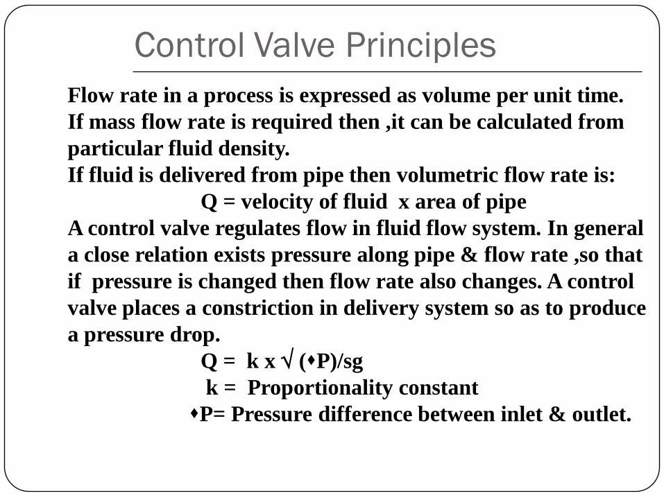
Flow rate in a process is expressed as volume per unit time.
If mass flow rate is required then ,it can be calculated from
particular fluid density.
If fluid is delivered from pipe then volumetric flow rate is:
Q = velocity of fluid x area of pipe
A control valve regulates flow in fluid flow system. In general
a close relation exists pressure along pipe & flow rate ,so that
if pressure is changed then flow rate also changes. A control
valve places a constriction in delivery system so as to produce
a pressure drop.
Q = k x (P)/sg
k = Proportionality constant
P= Pressure difference between inlet & outlet.
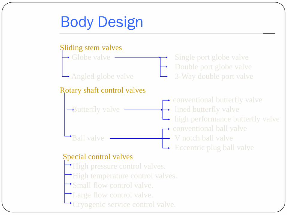
Body Design
Sliding stem valves
Globe valve Single port globe valve
Double port globe valve
Angled globe valve 3-Way double port valve
Rotary shaft control valves
conventional butterfly valve
Butterfly valve lined butterfly valve
high performance butterfly valve
conventional ball valve
Ball valve V notch ball valve
Eccentric plug ball valve
Special control valves
High pressure control valves.
High temperature control valves.
Small flow control valve.
Large flow control valve.
Cryogenic service control valve.

Globe valves
VIEW DRAWING
FEATURES
Tight shut off capability,Leakage less than 0.05% for single port & upto
0.01% for double port valve of rated Cv.Most common,simple .
APPLICATION:
Throttling purposes,general purpose valve ,applicable over wide
temperature range.
TYPES :
Single seat valve.
Double seat valve.
Three way valve for mixing/.diverting service.
ADVANTAGES :
Is fast to open or close.
Throttling to control any desired degree of flow.
Has positive shut off.
DISADVANTAGES :
These are quite heavy as compared to butterfly & ball valves.
Difficult to manufacture in small sizes.

Globe Valve Schematics
Singleport top guided
Single port split valve
Double ported globe valve
Figure 1

Single seat globe valve
Single seated globe valve are usually top guided ,such top guiding
minimizes the effect of the weight effect on valve & increases
resistance to trim vibration.
Most single seated valves are of unbalanced design tough balanced
design are made.They are used where tight shut-off is needed .Their
use in small body sizes ,2” & below,where tight shut off is needed.their
use in small body sizes is due to simple design & because ,for low flow
unbalanced forces are not enough large to require large actuator sizes.
Figure 1 Single port top guided
Advantages
•High rangeability
•Provides tight shut off
•Reversible plug available
•Used under application less than 2”.
Disadvantages
•Requires large actuator since it is unbalanced
•Low pressure recovery characteristics.

Double seated globe valve
These are generally top & bottom guided .here practical leakage
figure approaches 0.5% of the rated Cv ,because it is nearly impossible
to close both ports simultaneously, particularly when thermal expansion.
With the top & bottom guided construction , the stroke direction can be
reversed by simply inverting valve body.These are popular because of
their balanced design. The forces tending to close the valve are only
available with reverse plugs -constructed so that increasing loading
pressure moves the plugs into or out of the port .
Advantages
•High flow capacity compared to single port valves.
•High rangeability.
•Balanced design require small actuator.
•Used for sizes greater than 2”.
Disadvantages
•High leakage rate.
•Low pressure recovery characteristics.
•Likely to erode by high pressure drop.
•Not good for high flow,low pressure drop application
Figure 2
3-Way double ported valve
These 3 - way valve are extension of typical double ported globe valve .these
are available in two designs:
A) Diverting service B) Mixing service
A)Diverting service valve :
It has a modified double ported body ,with lower plug seat opposite to
the normal shut off position.either direct or reverse acting actuator is used
depending on fail safe condition. The body has a internal bridge to separate
the right hand & lower outlet.A diverting valve may be used for heat exchanger
bypass where heating medium enters port “C”.Part of the fluid leaves port “U”
to bypass the exchanger.the remaining portion of the fluid goes to the heat
exchanger through port “ L”,to heat an independent process stream & then
rejoins the bypass fluid stream from port “U”.
B)Mixing service :
Figure 3 illustrates 3-way valve used for combining service. Here two
separate fluids enter through “L” & “U”;respectively ,are combined in a
desired ratio & leave through common port “C”. The ratio control is achieved
by proper plug position. An upward movement of the plug decreases the flow
passing through port “U”& at the same time increasing flow through “L”.The
plugs are placed back to back in order for the flow direction will remain under
its plug.
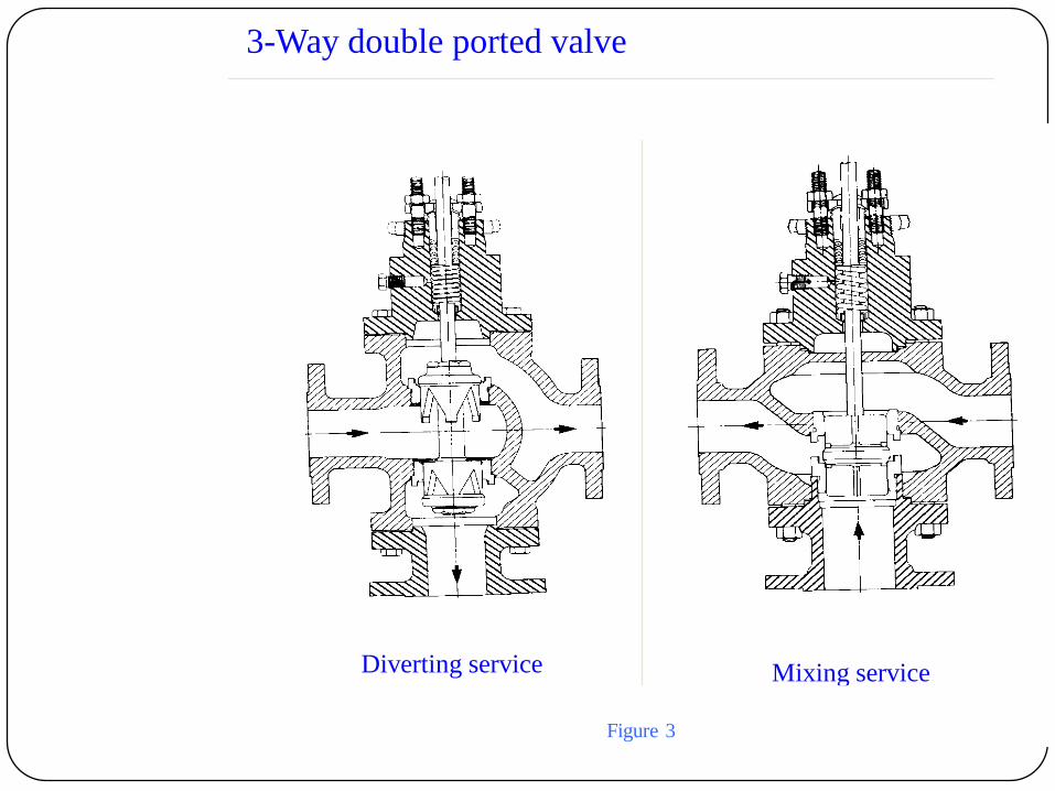
3-Way double ported valve
Diverting service Mixing service
Figure 3
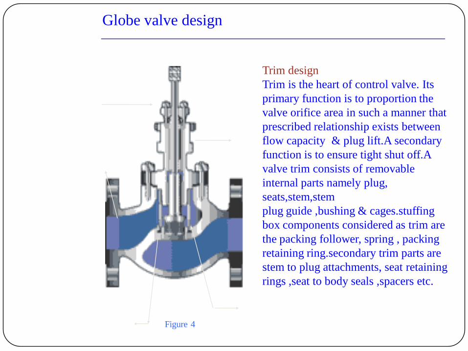
Globe valve design
Trim design
Trim is the heart of control valve. Its
primary function is to proportion the
valve orifice area in such a manner that
prescribed relationship exists between
flow capacity & plug lift.A secondary
function is to ensure tight shut off.A
valve trim consists of removable
internal parts namely plug,
seats,stem,stem
plug guide ,bushing & cages.stuffing
box components considered as trim are
the packing follower, spring , packing
retaining ring.secondary trim parts are
stem to plug attachments, seat retaining
rings ,seat to body seals ,spacers etc.
Packing
Plug
Stem
Seat ring
bonnet
Figure 4
Factor affecting trim design
• Temperature
• Pressure
• Flashing Fluids
• Cavitation
• Fluid Viscosity
• Solid Contents in Fluid
Each valve is given flow characteristic: i.e. for a given percentage of total plug
off the seat ,flow is given percent of the full open flow. This is true only when
pressure drop across valve is constant.this is known inherent flow characteristics
the installed flow characteristics may differ considerably at much higher pressure
drop .
Selection of valve trim is based upon
1) Knowledge of service pressure & flow conditions.
2) Manufacturers inherent flow characteristics for different trim shapes.
3) How inherent flow characteristics is altered by varying flow.
Maximum flow capacity depends upon seat port sizing, body design ,&plug lift
& type .
Shutoff & opening capability are determined by diameter of the mean seat to
plug seal contact ,pressure differential & available actuator force,provided the
stem design is adequate & allowance is made for seating force &packing friction.
Trim design for Maximum flow
Quick opening plug flow area
Maximum flow capacity in globe valve design is achieved by using the largest
possible flow orifice combined with a quick opening plug form.The orifice
should not be so large that valve body becomes a part of the total valve pressure
drop & changes flow characteristics.discharge flow area is equal to the orifice
area at lifts of 1/4-seat diameter.Turning fluid past the plug nose causes flow
resistance & an additional 10 - 15% lift is required to obtain maximum flow .
Thus total diameter is about 35% of orifice diameter to clear the plug out of the
flow capacity than globe type with equal seat orifice diameter.
Linear & equal percentage
Linear & equal percentage characteristics requires a plug plug nose extending
into the seat orifice and this must also be withdrawn to get full flow.In case of
contoured & v-port shape aids in turning flow gradually & lifts for maximum
are similar or slightly greater than for quick opening plugs ; usually ,about 45%
of orifice diameter for top guided plugs.
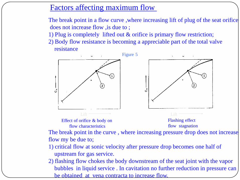
Factors affecting maximum flow
The break point in a flow curve ,where increasing lift of plug of the seat orifice
does not increase flow ,is due to ;
1) Plug is completely lifted out & orifice is primary flow restriction;
2) Body flow resistance is becoming a appreciable part of the total valve
resistance
The break point in the curve , where increasing pressure drop does not increase
flow my be due to;
1) critical flow at sonic velocity after pressure drop becomes one half of
upstream for gas service.
2) flashing flow chokes the body downstream of the seat joint with the vapor
bubbles in liquid service . In cavitation no further reduction in pressure can
be obtained at vena contracta to increase flow.
Lift Lift
Effect of orifice & body on
flow characteristics
Flashing effect
flow stagnation
Figure 5

Selection of Trim Material
Property Consideration
•Physical Properties
Tensile , Compressive , Shear ,Yield , Ductility, Hardness, Density.
•Thermal Properties
Creep,rupture ,Scaling(oxidation ),Hot Hardness, Cold Impact.
•Environment
Erosion Resistance.
•Corrosion
Chemical Resistance ,Electrolytic Potential With Body.
•Fabrication
Castability,machinability,finishing Surfaces, Method for Hard Facing.
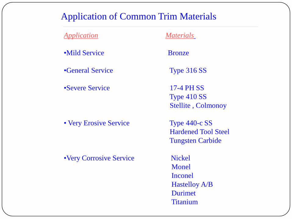
Application of Common Trim Materials
Application Materials
•Mild Service Bronze
•General Service Type 316 SS
•Severe Service 17-4 PH SS
Type 410 SS
Stellite , Colmonoy
• Very Erosive Service Type 440-c SS
Hardened Tool Steel
Tungsten Carbide
•Very Corrosive Service Nickel
Monel
Inconel
Hastelloy A/B
Durimet
Titanium

MATERIAL GENERAL USE GLOBE BUTTERFLY BALL PLUG DIAPHRAGM
STANDARD METALS GENERAL SERVICE A A UPTO 12" A A
CAST IRON MILD CORROSION A A UPTO 12" A A
DUCTILE IRON TO 650 °F A A UPTO 12" A A
TO 1000 PSI A A UPTO 12" A A
COST REDUCTION A A UPTO 12" A A
BRONZE(AL BRONZE) MILD SERVICE A VANES 12" TO 4" TO 2" A
CRYOGENIC SERVICE A VANES 12" TO 4" TO 2" A
OXYGEN A VANES 12" TO 4" TO 2" A
ALUMINIUM LIGHT WEIGHT - - TO 4" TO 2" A
CRYOGENIC SERVICE - - TO 4" TO 2" A
STEEL GENERAL USE A A A A A
ALLOY STEEL HIGH TEMPERATURE A - - - -
600°F-1050°F A - - - -
STAINLESS STEEL CRYOGENIC SERVICE A TO 12" TO 16" TO 12" A
1050-1200°F A TO 12" TO 16" TO 12" A
CORROSIVE SERVICE A TO 12" TO 16" TO 12" A
LINING ELASTOMER EROSIVE - A - A A
TIGHT SHUT OFF - A - A A
PLASTIC CORROSIVE - - - A A
TFE SEVERELY CORROSIVE 1-2" 4-12" 2-8" 2-12" A
GLASS - - - - A
INCONEL CHEMICAL SERVICE 1-4" - - - -
MONEL CHEMICAL SERVICE 1-4" - - - -
HSATELLOY CHEMICAL SERVICE 1-4" - - - -
ALLOY 20 CHEMICAL SERVICE 1-4" - - - -
TITANIUM CHEMICAL SERVICE 1-4" - - - -
GLASS CHEMICAL SERVICE - - TO 4" - -
AVAILABLE BODY MATERIALS
AVAILABLE LINING MATERIAL
CORROSION RESISTANT BODY ALLLOYS
A =AVAILABLE IN ALL SIZES
High temperature trim design
The material properties considered for high temperature application are
tensile ,yield ,creep & rupture .Other factors are scaling ,galling.
The design considerations include ;clearances of moving parts & fitted
parts as related to differential rate of thermal expansion of their respective
parts .
The yield,creep,compressive strength are lowered by high temperature .
Hot hardness is necessary to prevent galling & damage of seat.
The following design changes are considered for corresponding temperatures
Above 450°F - The bonnet extension requires a longer stem to keep the
packing cool.
Above 600 °F - Clearances must be increased .The plug & seat sealing areas
must be hard faced .
Above 750 °F - All threaded seat ring must be seal welded to prevent loosening
which will cause leakage & undercutting.
Above 900°F - All guided bushing ,plug guides & posts must be hard faced
tack welded .
Above 1050 °F- hard faced ,integral seat joints must be used .
Low temperature trim design
The trim design for cold & cryogenic services is based on following
requirements
1) Bubble tight sealing at low temperature .
2) Minimum heat leak.
3) Minimum cool down mass.
4) Quick change design.
5) Simple design.
6) Differential thermal contraction of materials
Bubble tight design ,is a must for in cryogenic service ,is obtained by using
TFE or KEL-F on the plug seal.both materials may also be used for the guide
bushing & seat joint gaskets.
The stems are passed through extended bonnets to prevent freezing of
atmosphere moisture.
Hollow plug are used to prevent rapid heat transfer ,yet allow a large diameter
plug plug for guiding & throttling stability.The void in the plug may be
evacuated or filled with insulating material to reduce radiant or convective
heat transfer.
Valves are either installed vertically or at 45° from vertical to maintain low
convective vapor lock in extended bonnet .
The weight of parts should be kept minimum to reduce cool down of mass &
boil-off loss of the liquefied gases entering the piping system.the plugs are
hollow & seats are integral with body.
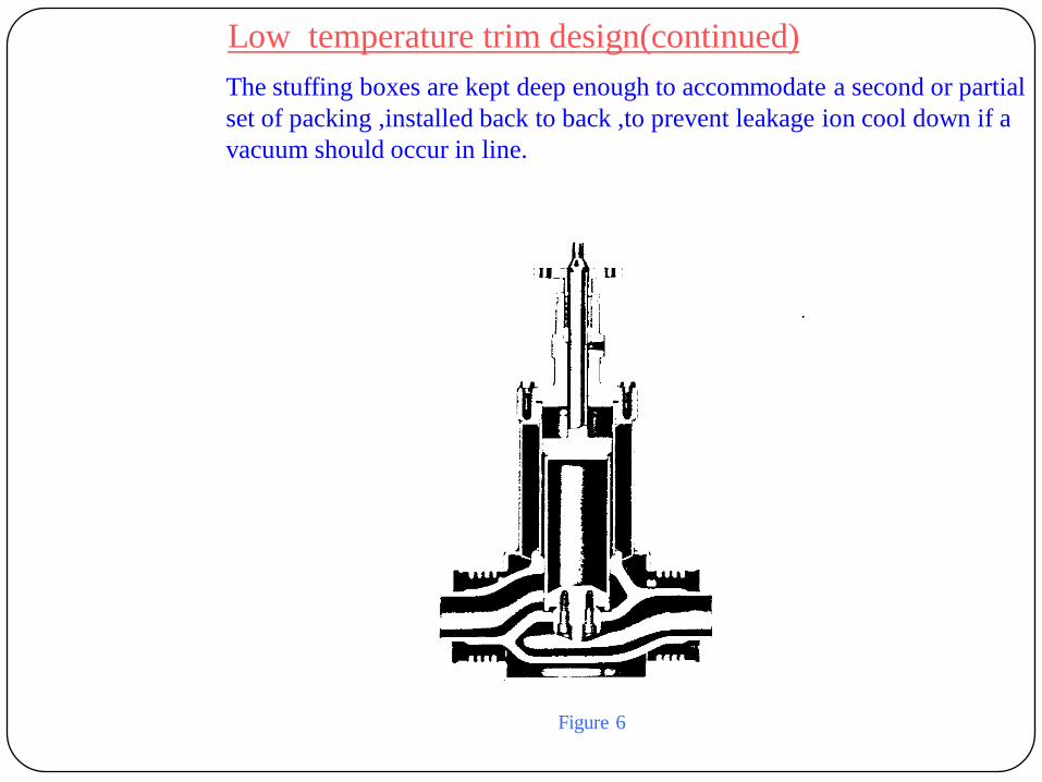
Low temperature trim design(continued)
The stuffing boxes are kept deep enough to accommodate a second or partial
set of packing ,installed back to back ,to prevent leakage ion cool down if a
vacuum should occur in line.
Figure 6
Low temperature trim design(continued)
Summary
Low Temperature Ranges Trim design requirements
Cold valve service (0 ° to -50 °F) - Extension bonnet with long stem,addition
of ethylene glycol in packing follower .
Cold valve service(-50 to -150 °F)- Extension bonnet with long stem to
prevent freezing .
Refrigeration service -The guide bushing may be tack welded to
prevent loosening from the differential
thermal contraction of bushing & bonnet.
Seat ring ,of screwed design are seal welded
to prevent loosening & leakage.
Cryogenic service(-150° to460°F) -a double extension bonnet with length 12”
for 320°F nitrogen service,& longer for
-450 °F hydrogen service.
Liquefied gases service - The guide bushing may be either welded or
(-259 to -450°F) the operating clearances for moving parts
may be increased by 50% to prevent binding
from differential thermal contraction.
Hollow plug extension is used .seatring are
of screwed design & are seal welded to
prevent loosening & leakage.
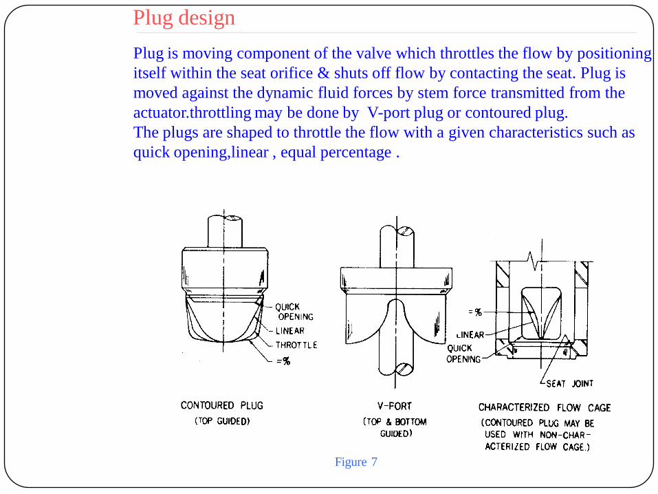
Plug design
Plug is moving component of the valve which throttles the flow by positioning
itself within the seat orifice & shuts off flow by contacting the seat. Plug is
moved against the dynamic fluid forces by stem force transmitted from the
actuator.throttling may be done by V-port plug or contoured plug.
The plugs are shaped to throttle the flow with a given characteristics such as
quick opening,linear , equal percentage .
Figure 7
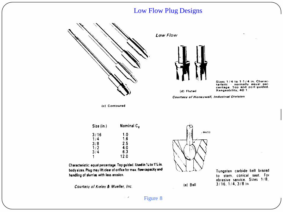
Low Flow Plug Designs
Figure 8

Regular Flow Plug Designs
Figure 9
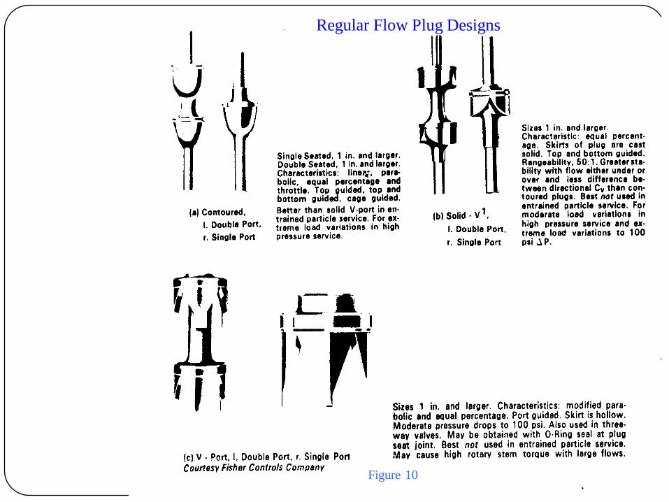
Regular Flow Plug Designs
Figure 10
Designing a plug to a selected flow characteristics
Theoretically Cv of a perfect orifice having one square inch are is 38.1
this means that an orifice with a efficiency of 100% would pass 38.1
gpm with pressure of 1 psi. No orifice has such efficiency ,& addition
of valve plug further reduces the efficiency.
When designing a flow characteristic for a plug, designer must attain
a specific flow ,corresponding to specific lift . To do so , we need to
know the efficiency of the annular seat plug orifice area .The efficiency
varies with the flow rate & the length of the restricted flow path .Also,
the body -flow resistance is a factor accounted for high lifts & each
type of body has different affect on resistance.
One method of plug design to make a preliminary flow test using a
rough shaped plug is designed to determined the flow efficiency curve
from Cv minimum to Cv maximum for that body. The plug is designed
to given flow characteristics using this data ,then it is flow tested & if
necessary reshaped slightly to follow flow curve.
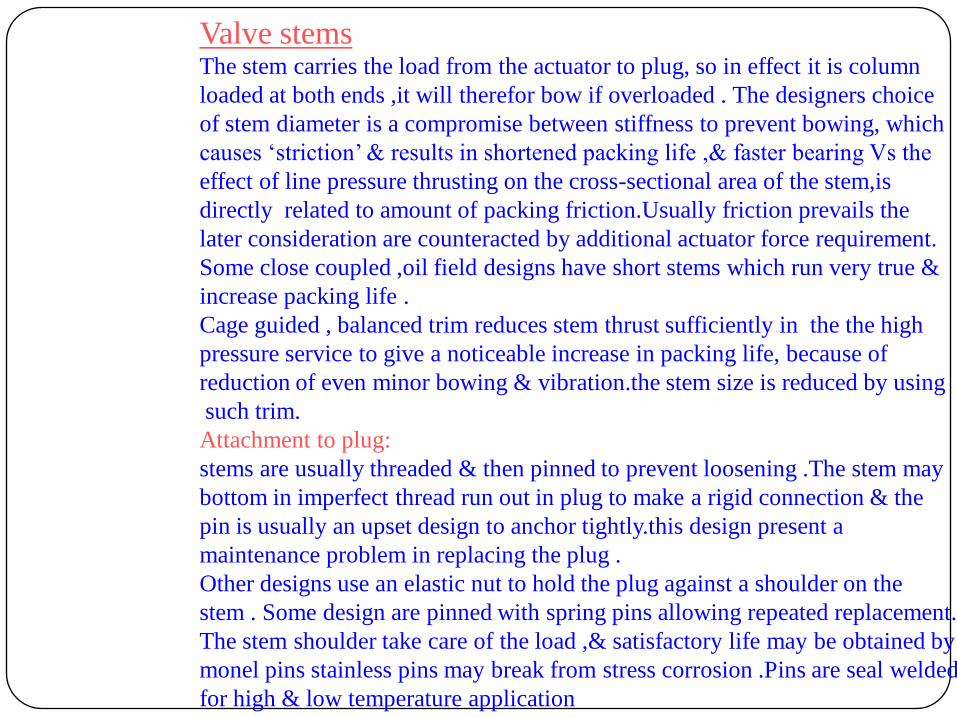
Valve stemsThe stem carries the load from the actuator to plug, so in effect it is column
loaded at both ends ,it will therefor bow if overloaded . The designers choice
of stem diameter is a compromise between stiffness to prevent bowing, which
causes „striction‟ & results in shortened packing life ,& faster bearing Vs the
effect of line pressure thrusting on the cross-sectional area of the stem,is
directly related to amount of packing friction.Usually friction prevails the
later consideration are counteracted by additional actuator force requirement.
Some close coupled ,oil field designs have short stems which run very true &
increase packing life .
Cage guided , balanced trim reduces stem thrust sufficiently in the the high
pressure service to give a noticeable increase in packing life, because of
reduction of even minor bowing & vibration.the stem size is reduced by using
such trim.
Attachment to plug:
stems are usually threaded & then pinned to prevent loosening .The stem may
bottom in imperfect thread run out in plug to make a rigid connection & the
pin is usually an upset design to anchor tightly.this design present a
maintenance problem in replacing the plug .
Other designs use an elastic nut to hold the plug against a shoulder on the
stem . Some design are pinned with spring pins allowing repeated replacement.
The stem shoulder take care of the load ,& satisfactory life may be obtained by
monel pins stainless pins may break from stress corrosion .Pins are seal welded
for high & low temperature application

VIEW DRAWING
Angle Globe Valve
FEATURES
Single seated valves with special body configuration to suit specific piping
& flow requirements.specifically designed for coking hydrocarbons,posses a
streamlined passage to prevent accumulation of solids on body wall.
APPLICATION
Hydrocarbon application ,low pressure application, may be used for abrasive
catalyst application.,self draining design of radioactive materials,Used where
turbulence ,cavitation effects are to be minimized.
ADVANTAGES
Hydrocarbon application.
Can handle erosive material.
Handles abrasive catalyst
Used where self draining is required.
High rangeability,high temperature rating.
DISADVANTAGES
Cannot be used for high noise application .
Avoided for throttling application.
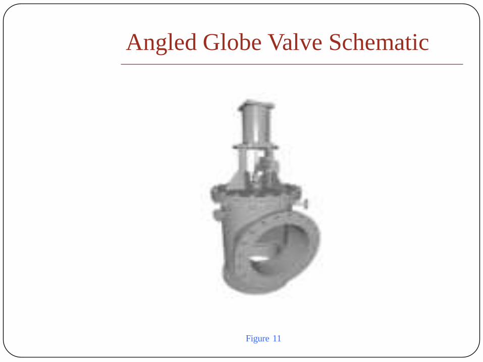
Angled Globe Valve Schematic
Figure 11
VIEW DRAWING
Ball Valve
FEATURES
Oldest of all valves,applied for wide range of application.
APPLICATION
Pressure control , flow control & shut off application .
Can be used for corrosive fluids,cryogenic fluids.
Used for high temp application, LPG application.
ADVANTAGES
Low pressure drop
Tight shut off.
Quarter turn application.
Small in size & lighter in weight.
DISADVANTAGES
Cannot be used for throttling application.
Avoided in quick opening application since it cause water hammer.
Fluid trapped in ball may cause corrosion.
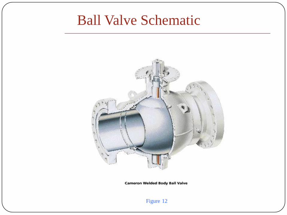
Ball Valve Schematic
Figure 12

VIEW DRAWING
Conventional Butterfly Valve
FEATURES
Described as damper/throttle valve.Operation carried out by
pneumatic,hydraulic,electric,manual operation.
APPLICATION
Low Pressure application where leakage is relatively unimportant.
ADVANTAGES
Simple .
Compact & quick opening .
Good controllability.
Low pressure drop.
Low weights & low cost.
DISADVANTAGES
Seals may be damaged if velocity is used
Require high actuating force.
Limited to low pressure application.
Elastomers limits temperature.

Butterfly Valve Schematic`
Figure 13
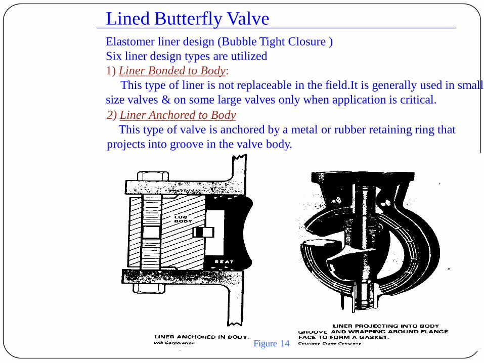
2) Liner Anchored to Body
This type of valve is anchored by a metal or rubber retaining ring that
projects into groove in the valve body.
Elastomer liner design (Bubble Tight Closure )
Six liner design types are utilized
1) Liner Bonded to Body:
This type of liner is not replaceable in the field.It is generally used in small
size valves & on some large valves only when application is critical.
Lined Butterfly Valve
Figure 14

3) Liner Wrapped Around Faces
The liner is wrapped around the flange faces of body in order to anchor it in
place & to from a gasket.controlled compression is obtained by extension of
rubber liner past the body flange face. The grooves allow displacement of
rubber liner on makeup of the valve in the piping without causing distortion
& disc binding.the design securely anchors the liner , only being surpassed by
the bonded type.
4) Push in Liner
This type of liner is made from an elastomer ring that is bonded to a metal
insert. This type of construction will provide stiffness for vacuum service &
will prevent extrusion by differential pressure across the disc .the liner is
readily replaceable in field .
Liner Wrapped Around Faces` Push in Liner
Figure 15

Lined Butterfly Valve (continued)
5) Clamped liner :
for this type of liner a split clamp holds both liner & pipe ends together .Seat
tightness may be adjusted by varying the split clamp bolting torque. Piping
must be moved aside to install & remove the liner . This type of liner is used in
food industries special pipe hubs are welded to the pipeline which are serrated
to fit raised concentric ends of the thicker liner ,thus giving positive axial
alignment of valve & piping.thicker lining allows deep penetration of the vane.
A lower torque is needed to seat the valve than with conventional liners.
Another type of design includes involves clamping a thin section liner by
means of an extension flange .The relief on the outside of the liner allows for
swelling .This design is operating satisfactorily with 3.55 slurry with 85 psi
shutoff pressure differential at 70°F.the liner may be replaced without
removing the stem & disc.
6) Special liners
The offset stem design of this valve allows two seating surfaces which are
interchangeable when the valve stem is centered on pipe axis. To change seating
surface,simply disconnect the disc from actuator & rotate it 180°

O ring Stem Seal Liner
Clamped liner:Figure 16
Figure 17

High Performance Butterfly Valve
The high performance butterfly valve are valves with double eccentric seating
geometry .these valves are extremely versatile as they could be used to handle
fluids for -45°C to 450°C .using variety of sealing system varying from
synthetic rubber-to-Teflon to metal-to-metal seating . By virtue of its double
eccentricity the valve disc allows friction free contact between the disc &
seat ring & as soon as the valve opens the disc moves away from seat ring
without any further frictional contact with the seat. This enhances the life of the
seal & reduces the valve torque considerably.new design with fish-tail disc
profile have been developed to especially encounter high pressure drop
application. The fish tail disc changes the pressure distribution curve across
it compared to conventional disc & move the resultant force closer to the valve
thereby reducing the dynamic torque. This design is hybrid between ball valve
& butterfly valve. The fish tail design valves are specifically used for throttling
application through 90° of rotation ,unlike conventional valves which are
restricted to 60° opening . This results in greater capacity per valve size.

High Performance Butterfly Valve
Figure 18
VIEW DRAWING
Rotary Eccentric Plug Valve
FEATURES
• Rotates through 50° angle with full open position & cams into the seat.
• Plug is free to rotate axially along its shaft to align with seat.
• Available from 1-24” in size.
• Applicable for temperature from -320 to 750 °C.
• Provides tight shut off.
• Requires low actuating force.
• Plugs are made up of hard stellite material
• Because of seals temperature & pressure ranges are restricted.
• Have high flow capacities & low pressure drops.
• The disc valve seals are highly reliable.
• High pressure recovery makes valve susceptible for cavation
• More expensive than butterfly valve.

Rotary Eccentric Plug valve
Schematic
Figure 19
High pressure control valves
Modern process employ working pressure above 6000 psig (414bar).Pressure upto
50000 psig are not unusual.at these high pressure the techniques & methods used to
seal valve bodies are very important.Usually the valve is of two piece angle design
with seat ring clamped between the two body halves .the seat ring to body seal is made
with retained, metallic ,hollow Oring .As pressure builds O -ring tends to allow line
pressure to enter the hollow correction of the O-ring .As pressure builds Oring tends
to inflate creating a tight seal between body seat & seat ring.the exterior surface of the
seat is plated with soft silver to assist in forming the seal.
Stem packing material:
Valve stem packing tolerances become more critical for high pressure units.At high
pressure elastomer packing can be extruded through very small clearances.Packing
compound is usually TFE compound impregnated with glass to make it more resistant
to extrusion.
Stem material:
The stem of these control valves are also made of high strength material such
as 4140 steel.The stem is short ,well guided & plated with chrome to prevent galling by
high pressure .
Valve bodies
Forged diecast bodies are used as high pressure bodies . The material is usually heat
treated type 4340 steel for pressure upto 50000 psig, & annealed steel SS316 for
pressures upto 10,000 psig. Forging process provides bodies free of voids & can be heat
treated to high strength
Valve plug :
The valve plug tip is made up of furnished tungsten carbide for resistance against corrosion
& abrasion. Actuation done by piston & diaphragm actuators.
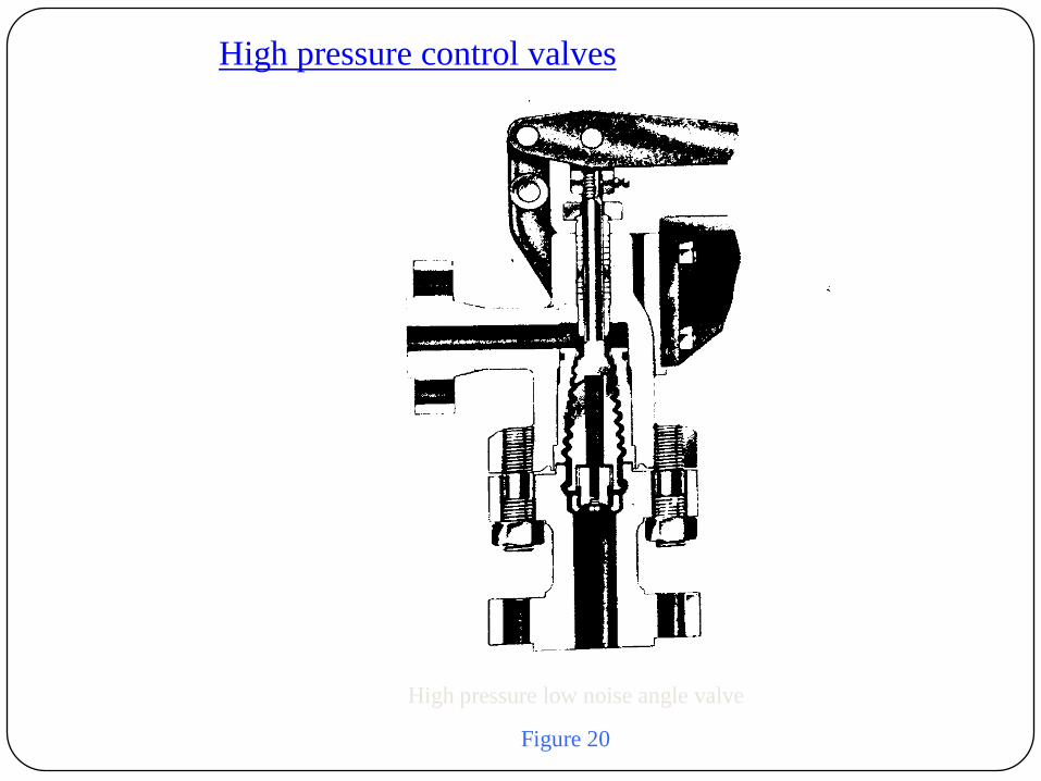
High pressure control valves
High pressure low noise angle valve
Figure 20
High temperature control valve
Control valves for service above 450°F must be designed & specified with temperature
conditions in mind . At elevated temperatures standard materials may be inadequate
plastics,elastomers & standard gaskets are insuitable & are to be replaced by more
durable ones .metal to metal seating materials are always used.
Packing material:
Semi metallic or laminated graphite packing spiral wound SS and asbestos gaskets are
used.
Valve body material:
Chrome -Moly steels are used for temperatures above 1000°F.
ASTM 4217 grade WC9 is used where there are chances of oxidation & scaling.
ASTM 4217 grade C5 used for shortcoming above 1100°F.
ASTM A351 grade CF 8M is applied for temperature 1500°F.
Trim materials
Chromeplated SS316
Cobalt based alloy 6
High vanadium
High chromium steels for additional resistance to high temperatures.

Small flow control valves
Applied in small pilot laboratories ,pilot plant ,commercial process plants .
These employ special trims for extremely small flow rates is necessary .The
special trim parts used are normally only two parts - a reduced port seat ring
& a valve plug with a tapered flat milled on one side . These parts are machined
to very low tolerances and are usually made of a hardened stainless steel or hard
faced with alloy 6 to minimize erosion.Using a 3/16 inch diameter port .
A
Angle flat “A” determines control of small flow rates
Seat ring
Figure 21
Small flow control valves
Low flow valves are those with Cv less than 0.05.There are many application
calling for small ,accurate control .In low flow characteristics the selection
criteria is quite different since there is absolutely negligible no frictional loss
in valve & there is no unfavorable pump head characteristics . There is no
need of equal percentage characteristics.From design stand point ,physical
physical dimension of the required are very small indeed ,the problem
incurred is high pressure drop with erosion problems .For such low flow rates
a actuator with a short stroke is required .The actuator has a smooth throttling
action for high pressure service .For less exacting services needles or pistons
with milled notches or slots are generally used in orifices ranging from 1/8 “
to 1/4 “.The valve stroke is of order of 1/2 “ .The Cv required is calculated by
conventional formulas & then next largest size trim is chosen. If the trim is too
small then a capacity increase is possible simply by increase in valve stroke or
slightly modifying valve plug.
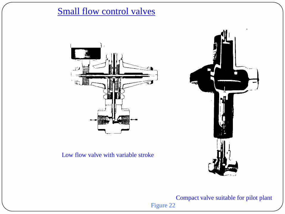
Small flow control valves
Compact valve suitable for pilot plant
Low flow valve with variable stroke
Figure 22
Large flow control valves
The globe style valve larger than 12” ,ball valves larger than 24” ,eccentric
plug valve larger than 24 “ ,butterfly valve 72 “ fall in special valve category
as valve size increases arithmetically the shutoff pressure increases
geometrically . Consequently then shaft strength ,bearing loads unbalance
forces & actuator forces become of greater significance. Normally maximum
allowable pressure drop is reduced on larger valves to keep design & actuator
requirement within limits even with lower pressure of the flow requirements
are awesome ,so naturally the actuator requirements are severe & long stroke ,
double acting pneumatic piston or electric actuators are specified for large flow
application. Installation & maintenance procedures are complicated .
For these type of valves the noise levels are carefully considered since noise
level increases indirect proportion with flow volumes .For keeping noise
under control the valve bodies cage type ,with usually long valve plug travel
with large number of flow opening.The fabricated valve body is designed for
for high pressure .
Over protection equipment must be included in downstream system to ensure
that the body shell & outlet connection are not subjected to pressure in excess
of rated capability.

Cryogenic & cold service control valves
When control valves are applied to operate at temperature below freezing
point , special precaution are taken .In certain cases special designs are
required .the principle problem is selection of proper materials of construction ,
particularly on moderately cold services (to -150 °F). Cryogenics is the term
applied for process operating in temperature range below (-150°F).
In temperature range (-20 to 150°F ) special impact resistant carbon steels are
used for pressure containing parts,the commonly used parts are of carbon steel
(grade LCB).
In temperature range (-20 to 50 °F)3.5% nickel steel (grade LC3) is used .
Valves are generally equipped with plain extension bonnet .In these temperature
range the primary objective is to reduce influx of heat system to reasonably low
value ,& to prevent packing box .The simple extension box is installed in
upright position to minimize heat transfer in operating fluid .
At cryogenic temperatures , material of construction now exclude carbon steel &
include austentic stainless steel .bronze, monel.
A special attention is paid to design bonnet.Care is taken that no liquefied gas
is trapped in bonnet space , where vaporization could generate dangerously high
pressures.in all cases the valve is completely insulated the process piping &
valves in cold section are often installed in “cold box”.the valve in this case
may have exceptionally long ,plain extension bonnet .

Cryogenic & cold service control valves (continued)
“cold box “ valve plug & seat arrangement
A large diameter bonnet selection is fabricated from stainless steel & brought
out through the cold box.This permits removal of trim,with seat ring & plug,
without disturbing valve body.
Figure 23
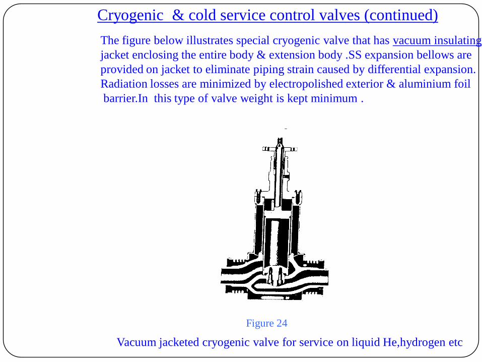
Cryogenic & cold service control valves (continued)
The figure below illustrates special cryogenic valve that has vacuum insulating
jacket enclosing the entire body & extension body .SS expansion bellows are
provided on jacket to eliminate piping strain caused by differential expansion.
Radiation losses are minimized by electropolished exterior & aluminium foil
barrier.In this type of valve weight is kept minimum .
Vacuum jacketed cryogenic valve for service on liquid He,hydrogen etc
Figure 24
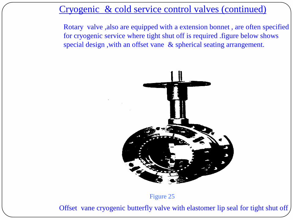
Cryogenic & cold service control valves (continued)
Rotary valve ,also are equipped with a extension bonnet , are often specified
for cryogenic service where tight shut off is required .figure below shows
special design ,with an offset vane & spherical seating arrangement.
Offset vane cryogenic butterfly valve with elastomer lip seal for tight shut off
Figure 25
Control valve flow characteristics:
The valve plugs for control valves described in earlier chapters are available in a
variety of geometric shapes, each with a characteristic relationship between
fractional valve lift & the relative flow through the valve. This relationship is
denoted as the flow characteristics.The proper selection of the flow characteristics
is an important part of control valve application.
If the valve gain or sensitivity is defined as Kc= Change in flow/Change in lift,
then it is evident that slope of flow characteristic curve is the valve gain.(Ref.
Fig.1)
In a control system valve gain (Kc) & process gain (Kp) are singular variables
which must compensate each other if control loop has to remain stable. The basic
concept of choosing a characteristics lies in gain matching of the valve & the
process.
The quick opening characteristics provides large changes in flow for small
changes in lift, therefore it usually has too high a valve gain for use in modulating
control.
It is limited to on-off service such as sequential operation in either batch or semi-
continues processes.
The bulk of control applications use valves with linear, equal %,or modified flow
characteristics. The modified characteristics generally fall between the linear &
equal% characteristics shown in fig1.
The linear characteristics provides a change in flow which is linear with valve lift &
thus
With signal to the valve. The linear characteristics would seem intuitively to be most
desirable characteristic for control, since it provides constant valve gain throughout the
stroke at constant pressure drop. However inclusion of the valve into a system ,with
associated piping equipment, & control loop, leads to considerations which generally
make equal % the most widely applied characteristic. The equal % characteristics
produces a change in flow, with change in lift, that is a constant % of the flow before the
change was made.
Putting in simple terms,
Assign equal % characteristics to a control valve if,
1)Process is fast
2)High rangeability is desired
3)When system dynamics are not well known.
4)Control valve is required in an application like heat exchangers where an increase in
product
rate requires much greater increase in heating /cooling medium.
5)The major portion of control system pressure drop is not available through the control
valve.
Assign Linear valve characteristic to a control valve if,
1)Process is slow
2)Where more than 40 % of the system pressure drop occurs across the valve
3)When major process changes are a result of load changes

Flow characteristics
Figure 25
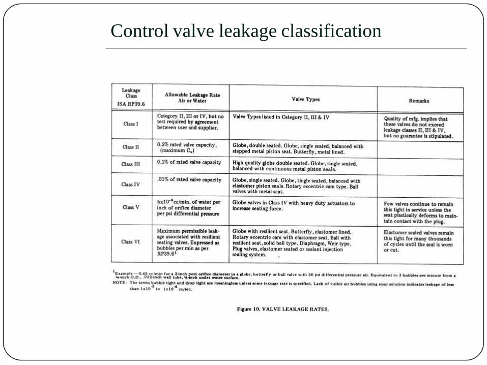
Control valve leakage classification
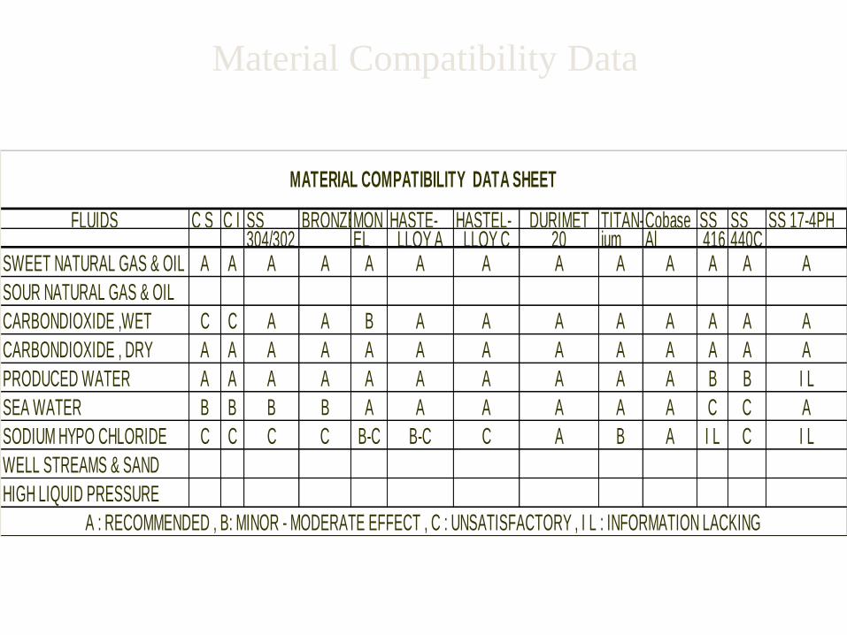
FLUIDS C S C I SS BRONZE MON HASTE- HASTEL- DURIMET TITAN-Cobase SS SS SS 17-4PH 304/302 EL LLOY A LLOY C 20 ium Al 416 440C
SWEET NATURAL GAS & OIL A A A A A A A A A A A A A
SOUR NATURAL GAS & OIL
CARBONDIOXIDE ,WET C C A A B A A A A A A A A
CARBONDIOXIDE , DRY A A A A A A A A A A A A A
PRODUCED WATER A A A A A A A A A A B B I L
SEA WATER B B B B A A A A A A C C A
SODIUM HYPO CHLORIDE C C C C B-C B-C C A B A I L C I L
WELL STREAMS & SAND
HIGH LIQUID PRESSURE
A : RECOMMENDED , B: MINOR - MODERATE EFFECT , C : UNSATISFACTORY , I L : INFORMATION LACKING
MATERIAL COMPATIBILITY DATA SHEET
Material Compatibility Data

Control valve sizing:
Factors to be considered
•Flow application data:
Maximum & minimum flow rates,upstream & downstream pressure.
Stream temperature.
•Fluid data:
Name & properties of fluid, Phase of fluid ,density of fluid ,viscosity of
fluid,vapor pressure.
•Piping influences:
Presence of reducers or other disturbances at valve .
•System influences :
Control dynamics,
Economic factors .
Safety.
•Style of valve:
Capacity ,
Rangeability
Corrosion or erosion.
Special requirements.
•Sizing:
Manufacturers sizing coefficient.
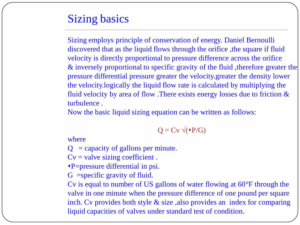
Sizing basics
Sizing employs principle of conservation of energy. Daniel Bernoulli
discovered that as the liquid flows through the orifice ,the square if fluid
velocity is directly proportional to pressure difference across the orifice
& inversely proportional to specific gravity of the fluid ,therefore greater the
pressure differential pressure greater the velocity.greater the density lower
the velocity.logically the liquid flow rate is calculated by multiplying the
fluid velocity by area of flow .There exists energy losses due to friction &
turbulence .
Now the basic liquid sizing equation can be written as follows:
Q = Cv (P/G)
where
Q = capacity of gallons per minute.
Cv = valve sizing coefficient .
P=pressure differential in psi.
G =specific gravity of fluid.
Cv is equal to number of US gallons of water flowing at 60°F through the
valve in one minute when the pressure difference of one pound per square
inch. Cv provides both style & size ,also provides an index for comparing
liquid capacities of valves under standard test of condition.
CONTROL VALVE SIZING:
To be a good aircraft pilot it is necessary to have the seat of the pants feel of the
ship. It is also important to know why the ship responds the way it does. For the
same reasons, the art of valve sizing goes hand in hand with the science of fluid
mechanics.
Incompressible fluids: (LIQUIDS)
A fluid flowing through control valves follows the same laws of conservation of
mass & energy as expressed in the equations of fluid mechanics. First conquered
the flow of liquids, which essentially are incompressible fluids. When any fluid
flowing inside a pipe, passes through a narrow passage or restriction, it must
accelerate. The energy for this acceleration must be taken from the pressure of the
fluid, or the static head. After passing the restriction, the fluid slows down again &
part of this head is recovered.
Neglecting friction & other non-ideal influences for a moment, Bernoulli‟s
theorem gives us the equation,
Where Q is flow through control valve, A2 is area at vena contracta, p1 is
upstream pressure, and p2 is downstream pressure & is density at operating
conditions.
After further simplification it works out to be,
Q = Cv (P/G)
where Q is flow of liquid through pipeline, G is operating density & P is
differential pressure across control valve.

We will have to consider two important factors, which affect calculations of Cv
for liquids
1)Piping geometry factor (Fp): Ideally we had considered same size of piping as
that of a control valve, but in practice there are always reducers/expanders
upstream/downstream of control valves & you have to correct for this change
from ideal condition.
2) Viscosity factor (F ): When flow is turbulent there is no problem & correction
factor is not required. But the moment the viscosity becomes low & flow starts
getting laminar, we will have to apply correction to the Cv using viscosity
correction factor.
The calculation sheet enclosed gives details of these factors & also elaborates
methods of calculations for these factors & their use in calculating corrected Cv.
Above we have seen the fundamentals of control valve sizing for liquids, which
are non-cavitating & non-flashing.
We will now turn our attention to two important phenomena, namely Cavitation &
Flashing. These phenomena are of significant interest in any comprehensive
discussion of control valves since their occurrence will affect the valve sizing
procedures, may introduce noise & vibration & also may limit the life expectancy
of the valve components & immediate downstream piping.
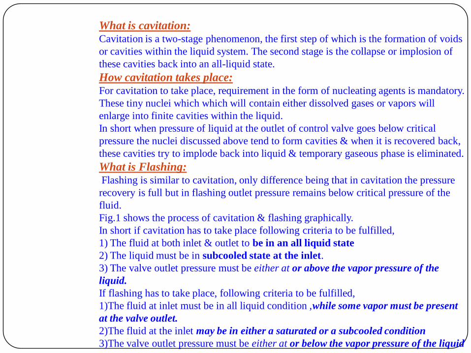
What is cavitation:Cavitation is a two-stage phenomenon, the first step of which is the formation of voids
or cavities within the liquid system. The second stage is the collapse or implosion of
these cavities back into an all-liquid state.
How cavitation takes place:For cavitation to take place, requirement in the form of nucleating agents is mandatory.
These tiny nuclei which which will contain either dissolved gases or vapors will
enlarge into finite cavities within the liquid.
In short when pressure of liquid at the outlet of control valve goes below critical
pressure the nuclei discussed above tend to form cavities & when it is recovered back,
these cavities try to implode back into liquid & temporary gaseous phase is eliminated.
What is Flashing:Flashing is similar to cavitation, only difference being that in cavitation the pressure
recovery is full but in flashing outlet pressure remains below critical pressure of the
fluid.
Fig.1 shows the process of cavitation & flashing graphically.
In short if cavitation has to take place following criteria to be fulfilled,
1) The fluid at both inlet & outlet to be in an all liquid state
2) The liquid must be in subcooled state at the inlet.
3) The valve outlet pressure must be either at or above the vapor pressure of the
liquid.
If flashing has to take place, following criteria to be fulfilled,
1)The fluid at inlet must be in all liquid condition ,while some vapor must be present
at the valve outlet.
2)The fluid at the inlet may be in either a saturated or a subcooled condition
3)The valve outlet pressure must be either at or below the vapor pressure of the liquid
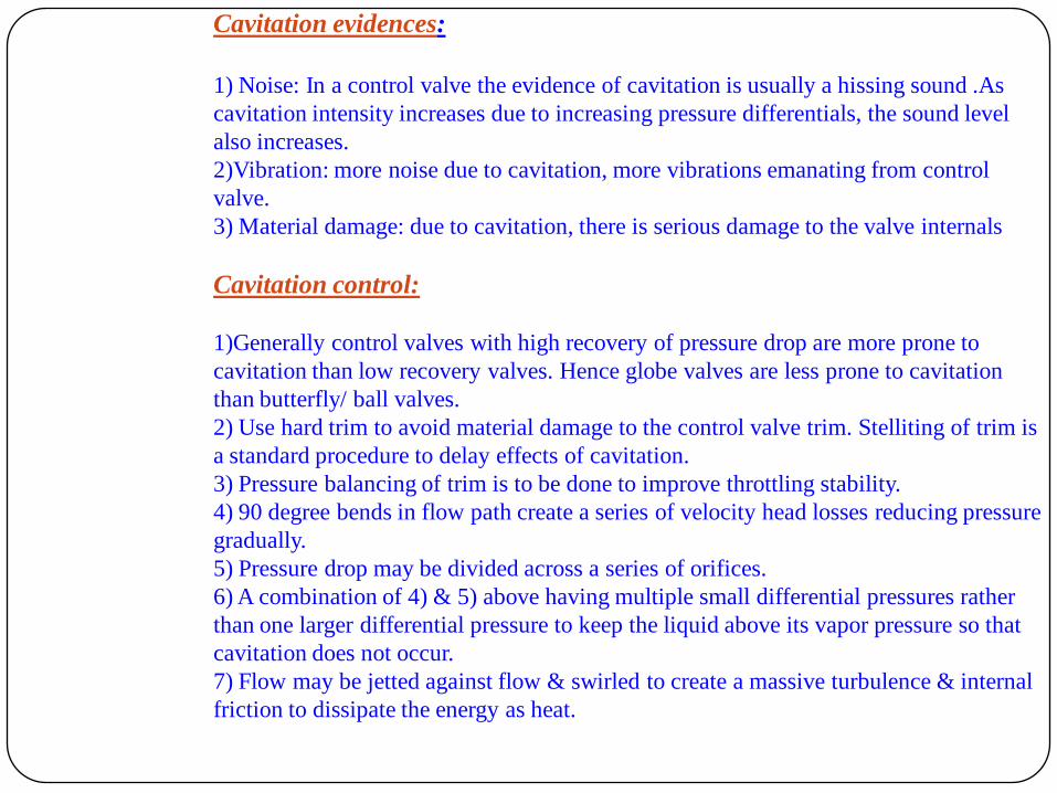
Cavitation evidences:
1) Noise: In a control valve the evidence of cavitation is usually a hissing sound .As
cavitation intensity increases due to increasing pressure differentials, the sound level
also increases.
2)Vibration: more noise due to cavitation, more vibrations emanating from control
valve.
3) Material damage: due to cavitation, there is serious damage to the valve internals
Cavitation control:
1)Generally control valves with high recovery of pressure drop are more prone to
cavitation than low recovery valves. Hence globe valves are less prone to cavitation
than butterfly/ ball valves.
2) Use hard trim to avoid material damage to the control valve trim. Stelliting of trim is
a standard procedure to delay effects of cavitation.
3) Pressure balancing of trim is to be done to improve throttling stability.
4) 90 degree bends in flow path create a series of velocity head losses reducing pressure
gradually.
5) Pressure drop may be divided across a series of orifices.
6) A combination of 4) & 5) above having multiple small differential pressures rather
than one larger differential pressure to keep the liquid above its vapor pressure so that
cavitation does not occur.
7) Flow may be jetted against flow & swirled to create a massive turbulence & internal
friction to dissipate the energy as heat.
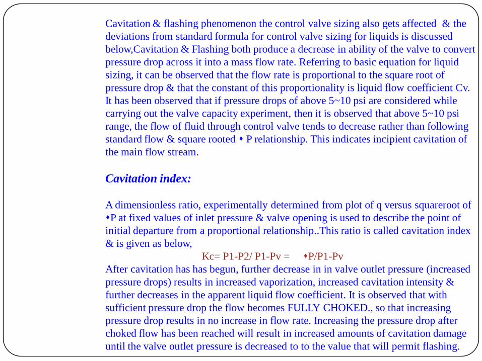
Cavitation & flashing phenomenon the control valve sizing also gets affected & the
deviations from standard formula for control valve sizing for liquids is discussed
below,Cavitation & Flashing both produce a decrease in ability of the valve to convert
pressure drop across it into a mass flow rate. Referring to basic equation for liquid
sizing, it can be observed that the flow rate is proportional to the square root of
pressure drop & that the constant of this proportionality is liquid flow coefficient Cv.
It has been observed that if pressure drops of above 5~10 psi are considered while
carrying out the valve capacity experiment, then it is observed that above 5~10 psi
range, the flow of fluid through control valve tends to decrease rather than following
standard flow & square rooted P relationship. This indicates incipient cavitation of
the main flow stream.
Cavitation index:
A dimensionless ratio, experimentally determined from plot of q versus squareroot of
P at fixed values of inlet pressure & valve opening is used to describe the point of
initial departure from a proportional relationship..This ratio is called cavitation index
& is given as below,
Kc= P1-P2/ P1-Pv = P/P1-Pv
After cavitation has has begun, further decrease in in valve outlet pressure (increased
pressure drops) results in increased vaporization, increased cavitation intensity &
further decreases in the apparent liquid flow coefficient. It is observed that with
sufficient pressure drop the flow becomes FULLY CHOKED., so that increasing
pressure drop results in no increase in flow rate. Increasing the pressure drop after
choked flow has been reached will result in increased amounts of cavitation damage
until the valve outlet pressure is decreased to to the value that will permit flashing.
Valve recovery coefficient:
An additional experimental coefficient is determined by flow test to approximate
the point above which no increase in flow rate is achieved for an increase in
pressure drop. This coefficient is called valve recovery coefficient
Km= Pm /P 1-Pvc
From the definition, it is clear that Km represents the fraction of the difference
between inlet pressure & choked flow vena contracta pressure that may be taken
as pressure drop across the valve, before choked flow occurs.
The procedure for sizing for choked flow condition is given in accompanying
procedure for Cv calculations.

Sizing for turbulent & noncavitating liquids
Formulae to be used:
Q = N1FpCv (P/G f)
Q= volumetric flowrate
N1=1.00 (US) =0.00865(SI)
Fp= piping correction factor
Cv=control valve coefficient
P= differential pressure
Gf =specific gravity
Wf = N6 FLP Cv (P)
N6 =63.3 (US)=2.73(SI)
FLP=combined pressure &
piping loss
Cv=control valve coefficient
P =differential pressure
=specific weight

Calculation for piping correction factor (Fp)
& Calculation for correction factor (FLP)
Fp = [ K/N2 (Cd)2 ] -1/2
FLP = [ 1/ (FL )2 Ki/N2 (Cd)2 ] -1/2
•N2= 890 (US)
=0.00214(SI)
•K=sum of coefficient heads
=K1 +K2+KB1+KB2
•K1=0.5[1-(d/D)2 ]2
•K2 = 1.0[1-(d/D)2 ]2
•KB1 = KB2 = 1-(d/D)
•Ki= K1 + KB1

Control valve sizing for choked flow
Formulae for Cv calculation:
Q = N1FLPCv (P-Pvc)/G f
Wf=N6FLPCv (P-Pvc)/G f
where :
Pvc= Ff*Pv
Ff =critical liquid pressure ratio factor.
=0.9996-0.28 (Pv/Pc)
Pv=vapor pressure of liquid.
Pc=thermodynamic critical pressure.
FLP =combined pressure & piping factor.
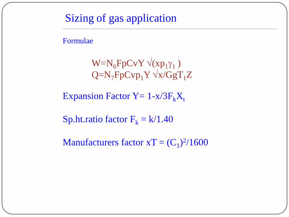
Sizing of gas application
Formulae
W=N6FpCvY (xp11 )
Q=N7FpCvp1Y x/GgT1Z
Expansion Factor Y= 1-x/3FkXt
Sp.ht.ratio factor Fk = k/1.40
Manufacturers factor xT = (C1)2/1600
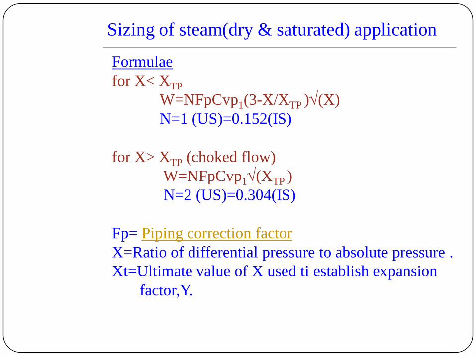
Sizing of steam(dry & saturated) application
Formulae
for X< XTP
W=NFpCvp1(3-X/XTP )(X)
N=1 (US)=0.152(IS)
for X> XTP (choked flow)
W=NFpCvp1(XTP )
N=2 (US)=0.304(IS)
Fp= Piping correction factor
X=Ratio of differential pressure to absolute pressure .
Xt=Ultimate value of X used ti establish expansion
factor,Y.
Actuators
•Pneumatic/Diaphragm actuators
•Piston actuators
•Electric actuators
Positioners
Boosters
Pneumatic ActuatorsProbably 90% of the actuators in the process are pneumatic.The reason for
their wide application is use of compressed air which is very good source of
power for actuators .The energy stored in compressed air provides a large
reservoir of readily available power to meet the needs of the actuators. The
reservoir formed by the air receiver & the distribution system will supply
power during short periods of power interruptions.Upto a point high pressure
air is more effective than low pressure air as far as actuators are concerned .
Taking economic factors into consideration ,the optimum system pressure is
between 60 to 120 psig.If cylinder actuated valves are used in plants economy
dictates that the pressure be at least 80 psig.
The quality of compressed is a important factor to be considered for safety ,
reliability & maintenance cost .Suitable air quality standard should be adopted
for the purpose.The air should be dried to a dew point at least 10°F below the
ambient temperature.The compressor should be non lubricated so there is no
oil present .Liquid ring avoid both oil & particulate problems.Many plants are
expected to run 100% of the time without failure ;yet many pumps in less
critical service are spared.
Other compressed gases may be used in place of air , for instance , natural gas
is often used on outdoor installation.other gas which is used is dry nitrogen
which is to be used should be oil free.Great care is to be taken to avoid the
hazard if pilots are located in closed areas where air can be displaced by
nitrogen.Even control rooms can be hazardous if ventilation fails.

Pneumatic ActuatorsAlso called diaphragm actuators.usually employ a flexible diaphragm,
placed between two stampings or cast ”casing”& at least one section is
made pressure tight .the actuator generally has a “range “ spring opposing
the force generated within actuator.The control air signal is connected to
pressure air tight chamber & an increase or decrease in pressure result in
force which is used to overcome the pressure -drop forces within valve
body, forces of actuator spring ,& hysterisis forces in valve body.the sole
purpose of actuator is to move the valve in response to error correcting
signal.The size of the actuator depends on the pressure drop in the valve.
Types of pneumatic actuators:
Direct acting - Air tight chamber is above diaphragm.
Reverse acting - Air tight chamber is below chamber.
Diaphragm materials:
Neoprene diaphragm with fiberglass.
Cotton /nylon-for ambient conditions.
Silicones,viton,polyacrylics with Dacron for high temperatures.
Fiber glass fabric.
Application
Widely used for proportional control.
Advantages:
Good adaptability.available in wide no.of sizes,least expensive in market.
Disadvantages:
Employ large diaphragm,large casting,imposes stresses on valve,not fast.

Pneumatic / Diaphragm Actuators
Figure 26

Piston Actuators/ Electro Hydraulic Actuators
The usual form of of a hydraulic actuator is a double acting cylinder .
Hydraulic fluid from a external source is admitted to one side of the piston
& exhausted from the other side of the 4 way pilot valve /jet type arrangement.
This pilot valve is governed by a control signal & a position feedback from
stem.An actuator of this type has the potential to exert enormous forces & to
drive the valve at high speed , since the remote motor & pump furnishing the
power can be as large as is necessary to match performance needs . Hydraulic
fluid is virtually incompressible so the actuator is extremely stiff .It can be
made fail safe by by installing a trip valve & an accumulator on the hydraulic
fluid line to store energy for use when the supply source fails .alternatively
an accessory lock up relay will hold the valve in last position.
Hydraulic actuators form an expensive system.There must be an unusual
requirement for high performance valve actuation to justify this expenditure.
The hydraulic actuators are likely to be found where there are a number of large
& heavy dampers, large ball valves ,large butterfly valve with high torque.
If these devices are to be moved at high speed ,or are used in control system
loop requiring superior performance , there is greater incentive to consider
hydraulic power .
The selection of right hydraulic fluid is an important point to be considered
for high temperature application.The system also requires filters,relief valves &
other accessories.

Piston actuators
These are available from most manufacturers.These are used along with
positioners .the piston cylinder used is made of cast/wrought iron withstanding
high pressure than stamped or cast casing.Due to high pressure rating the
actuators are able to provide more force for smaller diameters.It is considered
as effective means of coping pressure drops,when used along with actuators.
Application
Proportioning or positioning control valves.
Advantages:
Provide high thrust.
Good frequency response.
High reliability
Exact positioning relative to control signal.
Relatively fast response
Safe in electrically hazardous location.
Disadvantages:
Requires high pressure air supply.
More expensive than spring & diaphragm type.
Cumbersome to achieve fail safe condition
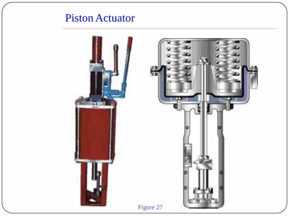
Piston Actuator
Figure 27

Electric Actuator
Actuator operation
The command signal for an electronic positioner is often 4- 20 mA DC ,but
could be no of other values . It tells actuator where the actuator should be
positioned . The actuator is usually designed to go fully closed at 4mA.&
fully open at 20 mA signal for direct acting .When actuator is closed at 20mA
& fully open at 4mA the actuator id reverse acting .
The actuator signal comes from a potentiometer other resistive element .it is
an electrical terminal that tells the servo where the actuator is positioned .
The comparator circuit compares the signal & actuator feedback signal.
1) If the signals are different then the comparator activates either the “open”
or “close” to minimize the difference .
2) For identical signal ,the comparator activates neither circuit .
3) The comparator should never activate both circuits at a time.
The output circuit features some form of switching element to connect the
power supply to motor leads.the switching elements are relays or TRIAC‟s.
open
close
Motor open
winding
Motor open
winding
Supply
Logic cktcomparatorInput
signal
Valve position Figure 28
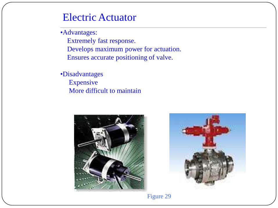
Electric Actuator
•Advantages:
Extremely fast response.
Develops maximum power for actuation.
Ensures accurate positioning of valve.
•Disadvantages
Expensive
More difficult to maintain
Figure 29
Selection of Actuators
Selection criteria :
1) Availability of powering source viz. Hydraulic, pneumatic,electric
mechanical.
2) Thrust requirement for the maximum pressure operation & tightness of
shutoff required to overcome friction versus the size available for each type
of actuator.
3) The availability of the actuator to hold the plug in a fixed position(stiffness)
through surges of line pressure .this is achieved by a high rate mechanical
spring ,low case air volume,hydraulic fluid loading .the rate of force change
of the actuator with stroke should be at least twice the rate of change of
line pressure unbalances in within the valve acting on the plug & stem.
4) The required actuating action upon failure of powering medium ; valve fails
open; valve fail close; close; hold position.
5) Adequate frequency response to satisfy process dynamic and /or safe
emergency full open or closing times .
6) Temperature limits of elastomer diaphragm material.
Neoprene(-20 to 180°F); silicone(-30 to 300°F); Viton(-10 to 350 °F)
metal bellows (> 350°F)
7) Actuator cost escalting in this order
Air diaphragm type,air piston, air rotary, electric & electrohydraulic type.

Actuator Sizing
When one selects an actuator following points should be weighed
carefully
•Torque required .
•Speed of response required .
•duty cycle limits.
•Energy Costs.
•Adjustibility for travel ,split ranging ,or other loops needs.
•Price of installation cost.
•Maintenance cost.
•Reliability .
•Space requirement & weight.
Actuator Sizing
Static Forces
The static forces are those forces that exist with the valve under pressure but
with no fluid flow .An ideal actuator should be able to overcome all the forces
associated with the valve .It should be able to move the valve mechanism to
specified position with specified tolerance ,despite the varying forces exerted
b the flowing fluid .In other words it should have power , stiffness & good
frequency response qualities suitable for application.
The static imbalance is a major force .On single ported ,unbalanced globe
valves this force is measured by the area of the seat multiplied by the
differential pressure.Even on balanced valve there is difference in the
opposing areas.The double port valve has unequal seat areas .To account for
these forces the areas of the seat & pistons must be known.The direction of
force depends on direction of flowing fluid .Another static forces is the stem
force .It is measured b the area of the stem multiplied by the pressure in the
valve body.
To meet the leakage tolerance the plug valve must be seated with appropriate
force.This force varies from about 20 lb per lineal inch of seat circumference
for class II leakage rate to about 80 lbs per lineal inch for the larger size valves
Class V valves require a seating force that increases with shut off pressure
differential across seat. Soft seated valves require fairly high seat loads to get
tight shut off. TFE requires a forces of 30 lbs plus a force of 22lb/in for each
100 psi differential pressure drop across it.max drop of TFE is 400 psi.

Static forces of rotary motion valves manifest themselves in a entirely
different manner .First Off ,the forces are measured in torque units .
Ball & other symmetric valves have no unbalanced forces .Ball valve
plugs are often designed so that closure member is always in contact
with the seat.These valves have extremely high seat frictional forces
at all opening .The other rotary valve incur sealing forces only at small
angles of opening .The torque required to cope up these forces are
“breakaway “or “breakout “torque.
Actuator Sizing
Actuator Sizing
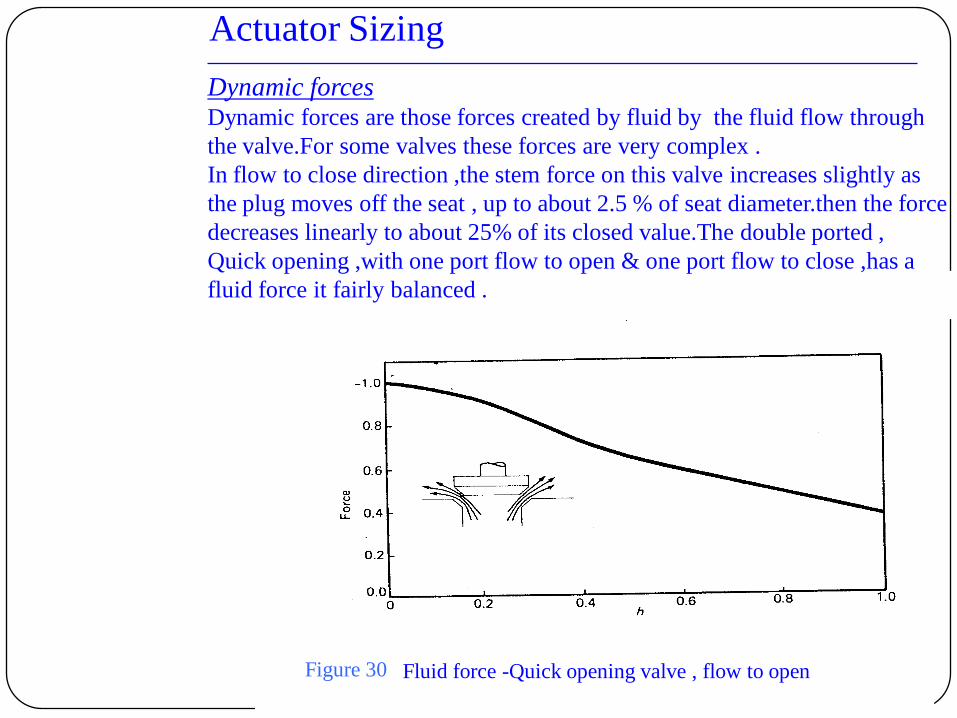
Fluid force -Quick opening valve , flow to open
Dynamic forcesDynamic forces are those forces created by fluid by the fluid flow through
the valve.For some valves these forces are very complex .
In flow to close direction ,the stem force on this valve increases slightly as
the plug moves off the seat , up to about 2.5 % of seat diameter.then the force
decreases linearly to about 25% of its closed value.The double ported ,
Quick opening ,with one port flow to open & one port flow to close ,has a
fluid force it fairly balanced .
Figure 30
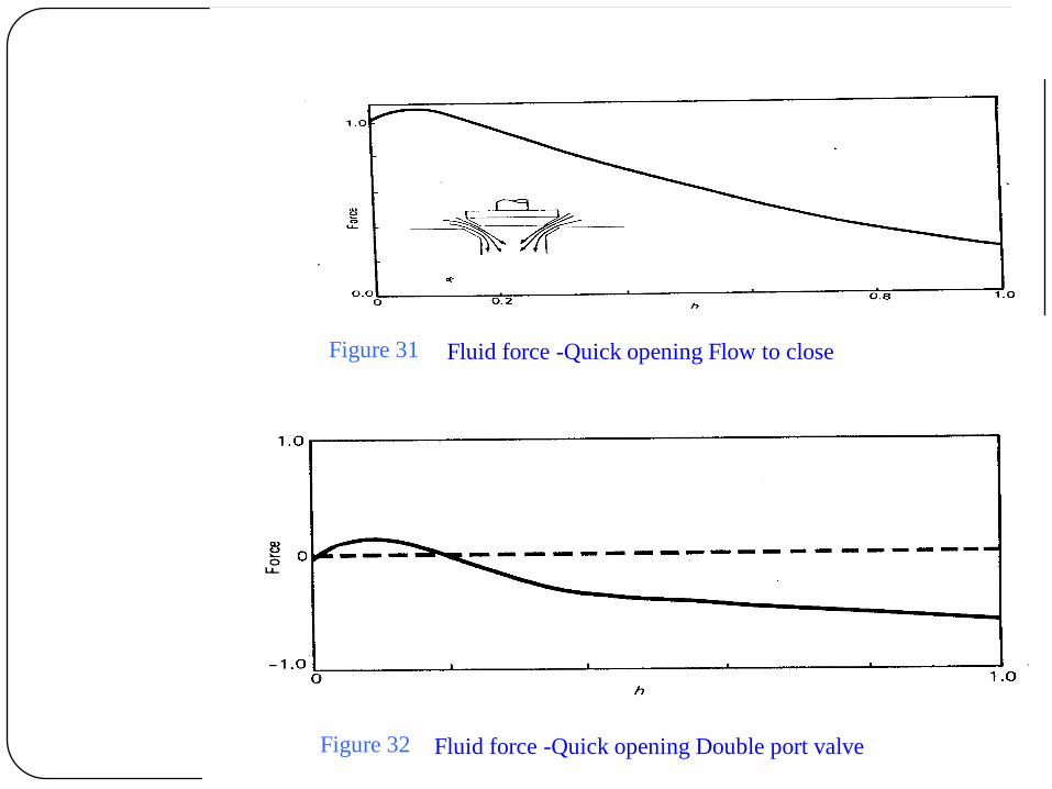
Fluid force -Quick opening Flow to close
Fluid force -Quick opening Double port valve
Figure 31
Figure 32
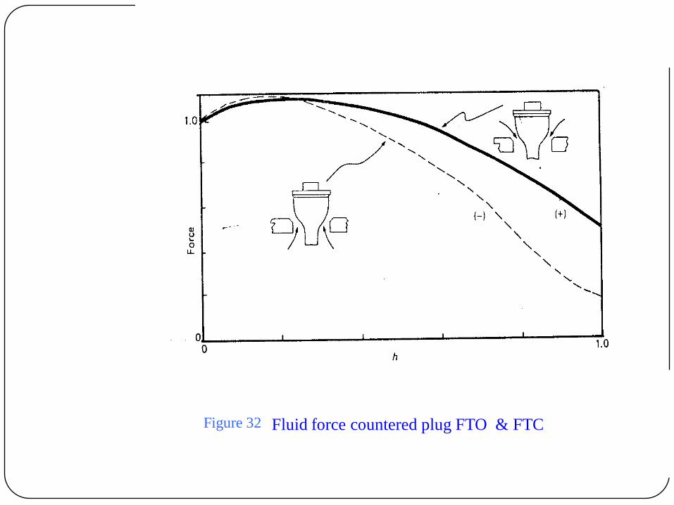
Fluid force countered plug FTO & FTCFigure 32
For Butterfly Valve-
The fluid forces acting on butterfly valves differ widely in design of the disk
& orientation of the stem .Consider first aligned disk with centered stem.
When the valve is closed there is no torque due to differential pressure .But
the thrust caused by the differential pressure on disk creates a substantial
friction on bearings. This adds to friction caused by packing & seal .As the
valve opens the vane ,the actuator must oppose the torque that tend to close
the valve the torque reaches the maximum value when valve is 60° to 80 °
open.As dynamic torque increases , thrust on the bearings is affected by lifting
forces on the disk,changing torque requirement of the actuator.The torque is
proportional to pressure drop & cube of diameter of disk.
The other factors affecting the torque curve for this type of valve are :
•The quality of bearings
•Lubricity of fluid
•Fitting adjacent to valve
•Free discharge
•Choked flow
•Compressible fluids

Torque curve for a butterfly valveFigure 33
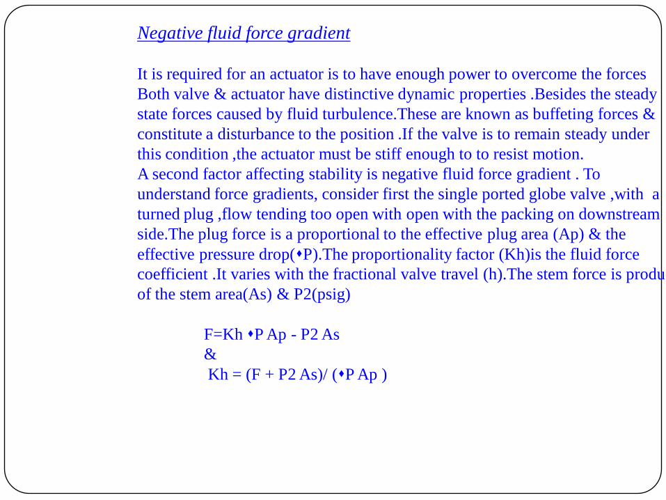
Negative fluid force gradient
It is required for an actuator is to have enough power to overcome the forces
Both valve & actuator have distinctive dynamic properties .Besides the steady
state forces caused by fluid turbulence.These are known as buffeting forces &
constitute a disturbance to the position .If the valve is to remain steady under
this condition ,the actuator must be stiff enough to to resist motion.
A second factor affecting stability is negative fluid force gradient . To
understand force gradients, consider first the single ported globe valve ,with a
turned plug ,flow tending too open with open with the packing on downstream
side.The plug force is a proportional to the effective plug area (Ap) & the
effective pressure drop(P).The proportionality factor (Kh)is the fluid force
coefficient .It varies with the fractional valve travel (h).The stem force is product
of the stem area(As) & P2(psig)
F=Kh P Ap - P2 As
&
Kh = (F + P2 As)/ (P Ap )

When the valve is in motion there are certain factors that assume importance
relative to valve stability .On balanced cage guided valves balancing piston
is connected to the body pressure by holes through the plug leading to
balancing chamber.
When plug moves moves ,fluid must flow through these passages .This
pressure .If the plug moves fast & holes are small ,there are will be substantial
pressure drop across the passages .this pressure difference in effect changes
the shape of the force curve & can create excessive negative fluid force &
instability.
On the other hand , rapid valve movement caused by fluid forces on actuator
in a manner to increase the effective spring rate ,thus increasing stability .
Movement of diaphragm or piston in the actuator causes air to flow in or out
of actuator case through small opening .This is a snubber & acts as an
additional spring force .If the valve time constant is ,at frequencies greater
than ( ) -1 radians/sec .The effective air spring rate is
Kp = k p (Ad)2 / V
Where
k = ratio of specific heats (sir=1,40)
p = average air pressure ,psia
Ad= Area of diaphragm,sq.inches
V =Volume ,cu.inches
Friction is dominant at natural frequency . Above natural frequency inertia
serves to increase the stiffness still further .At these frequencies less then
natural frequencies the air spring effect diminishes rapidly unless the valve is
equipped with positioner.Because of its high gain the positioner enables an
actuator to resist fluid forces that act at lower frequencies. As the frequencies
approaches ( ) -1 radians/sec stiffening effect diminishes to that of a valve
without positioner.
For choked flow there may be little or no pressure recovery.In that case the
P used in equation
Kh = (F + P2 As)/ (P Ap )
Is to be replaced by P e
P e= FL(P1-FFPV)
For gas or vapor the effective pressure drop P is
P e=Yx P1
And for choked flow
P e=0.44 Fk XT P1
In order to cope up with the problem caused by negative fluid gradient , the
valve manufacturer adopts certain design procedures to overcome the lack of
complete information.
One method is to list for each valve style & stem travel a factor to define the
slope of the negative gradient the factor is called Kn
Kn = (dF / dH)/(psi) -inches
The spring rate must be greater than (P Kn).
The operating pressure is taken as P .

To be able to properly size a control actuator ,one must have access
to all the necessary parameters ;
•Valve Body Force or Torque Characteristics .
•Packing & Seal Friction Factors.
•Actuator Force Characteristics.
•Spring Rates Available.
It is also necessary to know the limits of the various components like
•Seat Force
•Spring Load
•Spring Adjuster Travel
•Actuator Casing Pressure Limits..
Summary of actuator sizing
PositionerIt is a device which precisely positions ,by use of air ,the moving part
or parts of a pneumatically operated valve in accordance with a
pneumatic signal.
Principle of operation
A typical controller output varies from a minimum 0 psig to maximum 20 psig.
The most common valve spring operates at 3-15 psig.the air pressure above
15 psig is used to close valve against upstream pressure .
The figure below shows a valve with a positioner in addition to controller.
The signal from controller in this case goes to positioner instead of directly to
control valve. The positioner compares signal with the stem position .if the
position is not proper the positioner adds or exhausts air from the valve
actuator until desired position is obtained.
Application:
To overcome friction.
To increase shut-off rating of single seated valves.
To increase speed of response of control valve.
Split range operation.
To change flow characteristics.
To get wide proportional band.
Limitation:
•Hampers quality in fast process.so,boosters are used in modern day
application

Boosters
Volume boosters:
A volume booster can be used to increase the speed of operation of diaphragm
control valve .A volume booster being used in conjunction with controller &
pneumatic valve.the controller applies its output signal to booster instead of
to the control valve .Only about 1 cubic inch of air is required
to position the pilot in the booster , thus the volume of air moved through the
connecting tubing is small .The air that operates the valve comes through the
pilot in booster .The pilot has large capacity the stroking time is substantially
reduced .
35 psig
exhaust
controllerbooster
20 psig
Volume booster in control valve loopFigure 34

Boosters
Pressure boosters :
They are also volume boosters ,however their main function is to
increase the pressure from controller to above 20 psig. In certain valve
application.
A booster may be preferred over positioner because of its lower cost. Also
a booster does not close the loop around the valve. It also enhances stability
in fast response systems.
35 psig
exhaust
controller2:1
20 psig
Pressure booster in control valve loop
A-T-O
6 - 30 psig
Figure 35
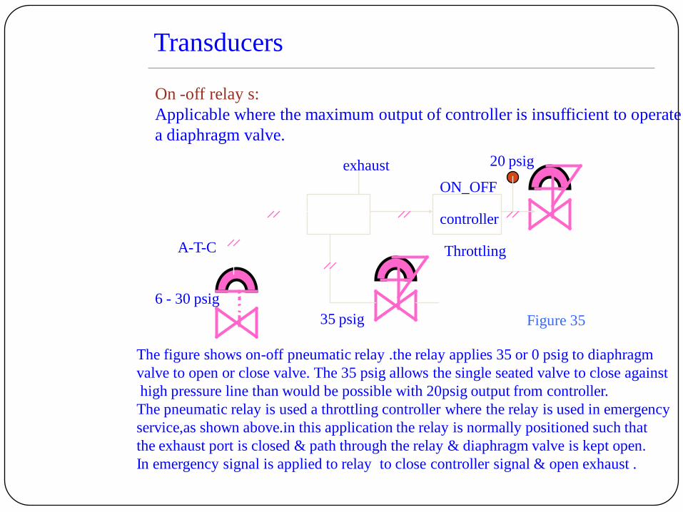
Transducers
On -off relay s:
Applicable where the maximum output of controller is insufficient to operate
a diaphragm valve.
35 psig
exhaust
controller
20 psig
A-T-C
6 - 30 psig
ON_OFF
The figure shows on-off pneumatic relay .the relay applies 35 or 0 psig to diaphragm
valve to open or close valve. The 35 psig allows the single seated valve to close against
high pressure line than would be possible with 20psig output from controller.
The pneumatic relay is used a throttling controller where the relay is used in emergency
service,as shown above.in this application the relay is normally positioned such that
the exhaust port is closed & path through the relay & diaphragm valve is kept open.
In emergency signal is applied to relay to close controller signal & open exhaust .
Throttling
Figure 35

Transducers
A-T-C
6 - 30 psig
35 psig
exhaust
Solenoid valves
On-Off control
Used in combination with diaphragm valve. It is used to supply or exhaust air
from diaphragm control valve to achieve on-off control.Depending on size the
arrangement may be considered less expensive & faster response.
Throttling control
The solenoid valve is used with throttling control valve in emergency service .
The solenoid valve is positioned such that exhaust port is closed & path
between controller & diaphragm is open .In emergency the solenoid coil is
activated & controlled is blocked & exhaust port is opened & valve is closed .
A-T-C
6 - 30 psig
35 psig
exhaust20 psig
Throttling
On off service Throttling service
SOV
SOV
Figure 36 Figure 37
