r igi s ystems - omnisomnisexteriors.com/wp-content/uploads/2016/04/omnis… · · 2009-08-31the...
TRANSCRIPT

LokRolld e s i g n a n d i n s t a l l a t i o n g u i d e
R IGI S SMETSY
R IGI S SMETSY
LOKROLL - Standing seam roof system
Contents
Page 1-3 Introduction / Fixing tools
Page 4-5 Liner sheets
Page 6 General Construction
Page 7 Structural Deck Construction
Page 8 Perforated Liner Construction
Page 9-11 Standard Components
Page 12-13 Components for Illustrated Constructions
Page 14 Properties
Page 15 Aluminium Paint Systems
Page 16 Load Span Tables
Page 17 Fixing Capacities
Page 18 Vapour Control
Page 19 Fire
Page 20 Expansion
Page 21 Production Tolerances
Page 22-23 Rooflights
Page 24-38 Inspection & Maintenance / Health and Safety / Handling
Page 39 Miscellaneous
Page 40-42 Installation - Measurement & Setting Out
Page 43-44 Verge details
Page 45 End Lap System Detail
Page 46 Ridge Detail
Page 47 Eaves Detail

LOKROLL - Standing seam roof system
Lokroll Dimensions
Roll Locking Action
Note: Template required for correct fixing, see page 2
1

The Lokroll system is available in 0.7 mm gauge plastisol/aluzinc steel or 0.9 and 1.2 mm gauge aluminium. Besides supplying the latter in plain mill finish or stucco embossed, other finishes and colours are available to add to the overall aesthetic appeal of the roof application as well as prolonging the life of the sheet.
Each sheet is positively anchored to the structure by means of a screw fastener in the concealed channel. The following sheet engages with the under lap rib and ‘rolls’ into its final location. The fixing screws are fully protected from the weather and are hidden from sight.
Corogrid Bar & BracketThe Corogrid brackets and support bar are manufactured from high quality 1.25 mm hot-dipped galvanised mild steel to BS EN 10143: 1993. The brackets, which incorporate a neoprene thermal break to reduce the effect of thermal bridging, are available in a range of heights to suit different thicknesses of insulation (or the pitch or roof required). In refurbishment applications the profile depth of the existing cladding will also determine the height of the bracket required.
ProfileThe Lokroll system is produced in a 500 mm cover
width.
Roof PitchBecause of the true standing seam concept of the Lokroll system the following pitches may be
maintained:
NB. Above falls must be achieved after consideration of loadings and deflection. Ensure gutter straps and edge flashing details at the eaves do not reduce the above roof pitches to avoid ponding of water at the sheet edge
Fixing ToolsFixing tools can be supplied with every contract and are refundable upon return.
It is essential that the following tools are supplied with every contract for Lokroll to ensure that the product is fixed correctly. It is important that they are utilised in the correct manner to guarantee absolute efficiency.
Profile Template
The template is manufactured in plastic and is positioned adjacent to the fixing point when the sheet is being fixed to ensure there is no spread of cover width.
It is essential that the template is used correctly.
To assist the operator, this tool is handed and the underlap side is clearly marked. It is imperative that this tool be used the correct way around. The number of templates required depends on the sheet length.
IntroductionContinuous sheet ridge to eaves 1.5°
Welded end lap joint 1.5°
Welded roof penetrations 1.5°
End lap joints with sealants and fixings 5.0°
2

LOKROLL - Standing seam roof system
Turn - up - Tool
Turn - down - Tool
Specifically designed to turn down the
pan of the profile at the eaves detail.
Turndown must be a minimum of 10˚
TURN
UP
TURN UP
TURN DOWN
Specifically designed to turn up the pan
of the profile at the ridge/hip detail.
3

Liner Sheet 20/200/1000
The 20/200/1000 profiled liner, with its 1000mm cover width provides an extremely cost effective solution in applications where the loading/span requirements are kept to a minimum. Available in 0.5mm/0.7mm gauge steel or 0.5mm/0.7mm gauge aluminium in a variety of finishes (depending on order quantity) the liner sheets can be supplied with either pan or fully perforated.
20/200 is available crimp curved if required, contact o u r Technical Department for details.
Walking boards should be used during installation, as they are not intended to support foot traffic. Fix the 20/200/1000 profiled liner sheet to the purlins with self-drilling screws in alternate troughs. Stitch side laps through crown of profile at 450mm centres and then seal side laps with continuous 50mm x 1mm Polybond Tape to provide air seal. Lap end laps by 150 mm and seal with 9 x 3 mm butyl tape or 3mm mastic bead.
When using a perforated liner or in high humidity applications a vapour barrier will be required to act as an air seal. End/side laps, ridge, eaves, verges and all penetrations should be sealed with continuous EPDM butyl tape.
4
30 30 20
1000
143
200
30
20

LOKROLL - Standing seam roof system
Liner Sheet 20/100/1000
The 20/100/1000 profiled liner is particularly suited to the Lokroll system. Available in 0.7mm gauge steel or 0.7mm / 0.9mm gauge aluminium in a variety of finishes (depending on order quantity) the liner sheets can be
supplied with either pan or fully perforated.
Walking boards should be used during installation, as they are not intended to support foot traffic. Fix the 20/100/1000 profiled liner sheet to the purlins with self-drilling screws in alternate troughs. Stitch side laps through crown of profile at 450mm centres and then seal side laps with continuous 50mm x 1mm Polybond Tape to provide air seal. Lap end laps by 150 mm and seal with 9 x 3 mm butyl tape or 3mm mastic bead.
When using a perforated liner or in high humidity applications a vapour barrier will be required to act as an air seal. End/side laps, ridge, eaves, verges and all penetrations should be sealed with continuous EPDM butyl tape.
5
25 43 35
1000
100
20

LOK
RO
LL - S
TAN
DA
RD
SY
STEM
- G
EN
ER
AL
CO
NS
TR
UC
TIO
N
6

LOK
RO
LL - S
TR
UC
TU
RA
L D
EC
K - G
EN
ER
AL
CO
NS
TR
UC
TIO
N
7

LO
KR
OLL
- P
ER
FOR
ATED
LIN
ER
- G
EN
ER
AL
CO
NS
TR
UC
TIO
N
8

LOKROLL - Standing seam roof system
BARRIER TAPE (When Lokroll is used in aluminium)
A closed cell foam tape 50mm wide, 3mm thick, supplied in 25 metre long rolls, to provide a thermal break between purlins and Lokroll cladding. Required for single skin and built up insulated applications. Wider tapes can be supplied for larger
hot rolled heavy duty steel support sections.
RIDGE FILLER AND SHROUD
A pressed aluminium section designed to fill and close off the open pan of the Lokroll. Holes are added to assist trickle ventilation. Supplied in mill finish, or coloured to match the external Lokroll coloured sheet. For angled ridges, or hips, special skew cut
ridge closures can be supplied.
RIDGE RETAINER
A 3 metre long aluminium extrusion to locate and retain the ridge closure into position. Fixed to the Lokroll standing seam with two Bulbtite rivets. Supplied in mill finish. Sections to be joined over
the Lokroll standing seam
RIDGE SUPPORT ZED
A 3 metre long aluminium pressing which supports the large verge flashings
EAVES FILLER
To close the corrugations in the profile, it is held in place by the drip angle
50
3
Standard Components
9

EAVES DRIP ANGLE
A 3 metre long aluminium extrusion, to locate the eaves closure, deflect wind blown rain and to strengthen the Lokroll sheet end. The eaves drip angle must always be fitted. Supplied in mill finish, it is fitted with a minimum of 3 bulbtite rivets.
FIXING SCREW/WASHERS
(Only used in aluminium construction)
An aluminium spreader washer, 80mm long, cut from an aluminium extrusion, strengthens the Lokroll fixing channel giving support for the screws above the
slotted holes. Supplied in mill finish.
A nylon bearing washer, 50mm diameter, helps to overcome frictional drag effects between the Lokroll sheet and thermal barrier tape (or breather membrane for a built up insulated application).
Fixing screws are stainless steel Corofix LSSF32, complete with a 16mm diameter sealing washer.
VAPOUR BARRIER
W e supply two types of vapour barrier. ULTRA2000 is a 2 x 50m, virgin polyethylene with a reinforcing grid of high density polyethylene. Supplied in rolls, 2 metres wide and 50 metres long. Weight per roll is 50.5 Kg (0.25 Kg/m2). This is generally used in conjunction with perforated liner panel systems.
An enhanced version of vapour barrier is Talfoil - an aluminium encapsulated membrane for use in areas of high humidity e.g. swimming pools.
RIVETS
Bulbtite, or Avdel TLR, type supplied in boxes of 100. Colour caps can be supplied to match the Lokroll coloured sheet. These rivets are required for fixing
the ridge retainer, gable starter, gable support
2
30
60
10

LOKROLL - Standing seam roof system
40mm
40mm
VAPOUR BARRIER TAPE
All joints of the vapour barrier and edges at eaves,
ridge and verge position to be sealed with butyl mastic
tape. Supplied in 22 metre long rolls 12mm wide and
2mm thick.
BREATHER MEMBRANE
The breather membrane is a spun bonded, micro
perforated, vapour permeable membrane supplied in
rolls up to 2.6 metres wide and 100 metres long.
COROGRID SPACER BAR
Corogrid support bars are manufactured from high
quality 1.25 mm Z35 hot-dip galvanised mild steel to
BS EN 10143 : 1993. The support bars feature a
unique dimpled fixing zone, which ensures fastener
security. Available in lengths of 1, 2 and 3 metres
(effective length) the bars have a spigot end to
maintain a continuous level of support.
COROGRID BRACKET
Corogrid brackets are manufactured from high quality
1.5 mm hot-dip galvanised mild steel to BS EN 10143
: 1993 (formerly BS 2989 : 1992). The base of the
bracket incorporates a neoprene thermal break which
minimises thermal bridging and acts as a vapour seal.
Brackets are available in a range of heights from
60mm to 250mm which is usually determined by the
thickness of insulation specified or pitch of roof
required. In refurbishment applications the profile
depth of the existing cladding will also determine the
height of bracket required.
Standard Bracket Heights (mm): 60, 80, 100, 120, 140,
160, 180, 200, 220, and 240.
Other bracket heights are available subject to quantity
11

Component Product Weight (kg/lm)
Top Sheet (0.7mm steel ) RigiSystems Lokroll 4.10
Top Sheet (0.9mm aluminium) RigiSystems Lokroll 1.82
Liner Sheet ( 0.4mm steel ) 20 / 200 / 1000 3.77
Liner Sheet ( 0.7mm steel ) 20 / 100 / 1000 6.60
Liner Sheet ( 0.9mm aluminium ) 20 / 100 / 1000 2.92
Component Description Code
Bar & Bracket Corogrid
Tissue Faced Rockwool Acoustic Slab (60 kg / m3 ) Thickness - 30mm TFVH/65/12060
Insulation to a 0.040 Lambda value (0.25 ‘U’ Value)
200mm thickness
Vapour Barrier 2m Wide x 50m Long Roll VBAR/01/02050
Polyethylene
Breather Membrane Standard Roll Size 1.6m x 100m
(other sizes available) BTHR/03/16100
Fixing Steel Lokroll to Bar and Bracket 2 No. Carbon Steel Self
or Main Purlins Drilling Screws 5.5mm FIX/LCS/55025
long with 16mm diameter
Twinseal Washers
Fixing Aluminium Lokroll to Bar and Bracket 2 No. Stainless Steel Self
or Main Purlins Drilling Screws 5.5mm FIX/LSS/55025
long with 16mm diameter
Twinseal Washer
Fixing Steel Liner to Thin Gauge Purlins 2 No. Carbon Steel Self Drilling
(1.4mm – 3.6mm thick) Screws 5.5mm x 32mm long FIXLCS/55038
Fixing Aluminium Liner to Thin Gauge Purlins 2 No. Stainless Steel Self
(1.4mm – 3.6mm thick) Drilling Screws FIXLSS/55030
5.5mm x 30mm long
Fixing Corogrid Bar and Bracket to Steel / Aluminium 2 No. Stainless Steel Self Drilling
Liner + Purlin (1.4mm – 3.6mm thick) Screws 6.3mm x 35mm long
with 16mm diameter Twinseal FIXLCS/55025
Washer and nylon bearing pad
Components for Illustrated Constructions
12

LOKROLL - Standing seam roof system
Stitching Steel Liner Sheet Self Drilling Stitcher Screws
6.3mm x 22mm long FIXSCS/63025
Stitching Aluminium Liner Sheet Aluminium Bulbtite Rivets
4.8mm x 12mm FIXRSS/48012
Grip Range 0.5mm - 6.4mm
Jointing Tape for Vapour Barrier 12mm Wide x 2mm Thick
Cross Linked Butyl Rubber VBAR/02/12222
22.5m long roll
Thermal Barrier Tape (for aluminium construction) Flexible tape 75mm wide x 33mm long TAPE/FX/75X33
Isolation Tape when using single skin Barrier Tape
Aluminium Lokroll to Galvanised Purlins 50mm Wide x 3m long roll BARR/01/50320
End Lap Sealant for Steel / Aluminium RigiSystems Lokroll Butyl Mastic
(> 50 roof - pitch) 19mm Wide x 3mm Thick TAPE/BM/06X02
Component Description Code)
13

Properties
Aluminium LokrollLokroll sheets are manufactured from aluminium alloy of the 3000 series containing magnesium and manganese for increased strength and
durability.
The alloy is designated as:
• EN AW- 3004 (Al Mn1 Mg1) or
• EN AW- 3105 H28 (Al Mn 1 Mg 0.5): to
BS EN 485-2 : 1995.
Minimum 0.2% proof stress being 200N/mm2.
Steel LokrollThe substrate used is hot dipped galvanised steel with a coating mass of 275g/m2 and a minimum yield strength of 220 N / mm2 to BS EN 10147.
The Table below Shows Comparison of BasicProperties of Both Metals
Density Modulus of Thermal Thermal Expansion Melting Point
Material (kg/m3) Elasticity (kN/cm2) Conductivity (W/m°C) in mm per°C (°C)
Aluminium 2705 6900 214 24 x 10-6 650
Steel 7850 21000 55 12 x 10-6 1900
For properties of Aluzinc, Stainless Steel, Zinc and Copper contact Technical.
14

LOKROLL - Standing seam roof system
Although aluminium is both stable and durable in most
environments, there may be the need to apply a colour
paint finish for very aggressive situations or for
aesthetic reasons, below are listed a few paint coat
options:
PVF2
This product is a primer with a Class 1 polyvinylidene
fluoride/acrylic paint system applied to a coating
thickness of 25mm. It is an extremely durable system,
giving excellent flexibility and chemical resistance,
combined with the highest possible performance with
respect to gloss retention, chalking and colour change.
However, it is easily scratched and must be handled
with care. It can be supplied with a strippable plastic
film as additional protection for site use.
ARS (Abrasion Resistant Surface)
The system is a primer with a polyamide modified
polyurethane paint to a coating thickness of 28mm,
this has very good durability and weatherability. Its
ultra violet performance is superior to that of plain
polyester. The main benefit of the system is that it
gives a surface that is highly resistant to abrasion.
Colourbond
This is an alkyd-amino based coating of 40mm
thickness applied by spray with electro-static attraction
to the metal and finally stove cured. This results in
some ‘wrap around’ at the edges, which ensures that
there are no exposed cut edges and is therefore useful
in aggressive environments. Due to the nature of the
process, sheets are limited to a maximum length of
6m.
Backing Coat
This is normally a 2mm lacquer coating with 6mm
chromated epoxy coating providing limited protection
and preventing damage to the top coat when in the
coil or in stacks of flats / sheets. It is not intended for
external exposure.
The ‘Decorative Life’ is the time period when a
decision to repaint may be required. The figures are
based on marine or industrial environments and may
be extended by 5 years for suburban or rural
environments.
The ‘Ultimate Life’ is based on a marine or severe
industrial environments and may be extended to 40
years for suburban or rural environments.
Aluminium Paint SystemsDecorative Life Ultimate Life Scratch Stain Colour Weathering Chalking
System (years) (years) Resistance Resistance Fastness Aluminium Resistance
ARS 15 25 Excellent Good Good Good Good
PVF2 15 25 Good Excellent Excellent Excellent Excellent
Colourbond 15 25 Good Good Good Good Moderate
15

Load Spans - Steel LokrollLokroll is generally used in a multi-span configuration. The load/span graphs below are characteristic working
loads in kN/m2 based on sheets being continuous over at least three spans.
Deflection under stated safe superimposed loading will not exceed span/200.
Deflection under stated safe uplift loading will not exceed span/90
16
1.00 1.25 1.50 1.75 2.00
Downward 4.88 4.40 3.73 3.13 2.45
Wind uplift 4.47 3.83 2.48 2.11 1.79

LOKROLL - Standing seam roof system
Ultimate Fixing Capacities
Structural steel Z35 Material
Screw 1.6mm 2.0 mm 2.5mm 2.8mm 3.2mm
5.5mm Diameter No 2pt 4.1 5.1 7.4 9.6 10.7
6.3mm Diameter No 3pt 4.1 5.3 7.6 8.3 9.9
Pull Out Strength (kN)
Sheet 16GB 19GB 29GB*
0.7mm Steel 5.6 5.7 6.9
0.7mm Aluminium 2.6 3.5 2.3
0.9mm Aluminium 3.2 4.1 2.6
* 16,19,29 = washer diameter (mm)
Washer Pull Over Values (kN)
Single Sheet (kN) Double Sheets (kN)
0.7mm Steel 0.98 2 x 0.7mm Steel 2.10
0.7mm Aluminium 0.65 2 x 0.7mm Aluminium 1.30
0.9mm Aluminium 1.00 2 x 0.9mm Aluminium 1.95
Stitcher Pull Out Values
Sheet (kN) Failure Mode 0.7mm Steel
2 x 0.7mm Aluminium 1.50
2 x 0.9mm Aluminium 1.53
Top hat to 0.70mm Steel Deck 1.53 Rivet pulled through aluminium sheet
Top hat to 0.90mm Steel Deck 2.20
Top hat to 1.10mm Steel Deck 2.20 Rivet failure
Top hat to 1.25mm Steel Deck 2.24
Pull Out Values For Bulbtite Rivets Type 6604/6/3W
We recommend a safety factor of 2.0 be applied to the above capacities to bring them into line with
characteristic working loads.
Materials yield - steel 220 N/mm_
- aluminium 200 N/mm_
17

Relative humidity is the ratio of water held in a given volume of air to the maximum amount that could be held at that temperature. If the temperature of the air is raised, the amount of water held is unchanged, but the amount required to saturate the air is increased. So, an increase in temperature causes a decrease in the relative humidity for this given volume of air.
Conversely, a reduction in temperature reduces the amount of water required to saturate the air and so the relative humidity increases. As the temperature continues to fall, the relative humidity will eventually rise to 100% and become fully saturated - this is known as the dew point. The surplus water in the air cannot be held as a vapour and is expelled as water droplets leading to condensation.
When moist air comes into contact with a cold surface the above cycle deposits water droplets on the surface causing surface condensation. This can occur in a ‘cold roof’ construction where vented flutes are incorporated to the underside of the top sheets.
The Ziplok system greatly reduces this risk by incorporating a high level of insulation, which is compressed tightly to the underside of the top sheet. This reduces the risk of air pockets and prevents the top sheet from becoming too cold. Furthermore, the seamed joints allow a natural venting of the roof system.
Humid air exerts a greater pressure than dry air, and will attempt to enter the roof construction through any available apertures. When condensate is formed in the cool zones of the roof this is known as interstitial condensation. Here, there is a local drop in pressure due to the removal of water vapour from the air. A minute distance away the air is warmer and contains a large quantity of water vapour and is therefore under
higher pressure. The high-pressure air will migrate to
where the pressure is lower, and more condensate is
formed. This process is continuous as long as the
temperature and relative humidity is maintained. To
combat this, a vapour barrier is required on the warm
side of the insulation in the roof build-up to prevent
humid air from gaining access to the cool zones of the
roof. In standard standing seam roof constructionsa sealed liner will act as a vapour control layer (see
P5 Liner Sheets). However in high humidity
applications or acoustic applications where a
perforated liner is used an additional vapour barrier will
be required.
Before installing a separate vapour control layer, any
water must be removed and the surface kept clean,
dry, smooth and free of any dirt and swarf. The vapour
control layer is spread loose, flat and without wrinkles
in the same direction as the liner sheet. End and side
laps should be sealed with a continuous run of 12mm
x 2mm cross-linked butyl rubber tape. The minimum
width of lap should not be less than 150mm. Where
puncture damage has occurred, good-sized patches
must be applied over the area ensuring a continuous
double bead of sealant all around the hole.
Our BBA Agrément Certificate No.99/3605 proposes a
choice of three VCL products:
• TALCHECK – 0.3mm thick lightweight
polyethylene with a Water Vapour Resistance of
272MNs/g, or
• ULTRA 2000 – 0.4mm thick reinforced
polyethylene with a Water Vapour Resistance of
522MNs/g, or
• TALFOIL – Reinforced foil vapour barrier with a
Water Vapour Resistance of 25,000MNs/g.
Vapour Control
18

LOKROLL - Standing seam roof system
Buildings should provide a safe environment and
building materials should not increase the risk of fire,
or increase hazards resulting from fire.
If a fire breaks out in a building there is a rapid build up
of heat, smoke and fumes. An aluminium roof is
weakened by the heat and the sheets will collapse
inwards allowing the heat and fumes to escape
because of its low melting point (650 °C). This reduces
the heat damage of the building structure, increases
the chances of occupants to locate the exits, and
assists fire fighters in gaining access to the source of
the blaze.
By contrast, a steel roof remains intact by virtue of its
meting point (1900 °C). The resulting increase in
temperature and toxic fumes can increase the loss of
life and the extent of damage.
AA ClassificationThe external skin is tested in accordance with BS476:
Part 3 and is given a designation in the range AA to
DD. The first letter refers to fire penetration
performance should there be a fire on the roof
deposited from adjoining burning premises. The
second letter refers to the resistance of surface spread
of flame resulting from the fire on the roof. Aluminium
achieves the designation AA, the highest possible
rating.
Class O ClassificationIf there is a fire in a building, the wall or ceiling lining
material must not help to spread the fire. The statutory
requirements of the Building Regulations approved
document B define the highest product performance
classification for a lining material as class O. To attain
this class, a material has to achieve the highest index
performance when tested in accordance with BS476:
Part 6 (for coated aluminium I = 3 & i = 1.5), and a class
1 rating when tested in accordance with BS476: Part
7. Aluminium satisfies this class O rating.
IgnitabilityBS476: Part 5 is a test for ignitability. Materials are
classified as ‘easily ignitable’ - X or ‘not easily ignitable’
– P. Aluminium receives the better rating, P.
Fire
19

By inspection a RigiSystems Lokroll sheet 20m long with a mill finish could experience an expansion of 20 x 1.08 = +21.6mm in hot weather and a contraction of 20 x 0.36 = -7.2mm in wintry conditions. It is important, therefore, that all roof details take account of all such possible changes in length, especially where the sheets meet abutments or gutters.
Aluminium Lokroll
When lengths of Lokroll exceed 5m in a light colour/mill finish or 7m in a dark colour (based on aluminium) it becomes necessary to make provision for thermal expansion and contraction. This is achieved by locating the fixing screws in slots, which are punched on site with a purpose made hand tool. A standard slot is 40mm long, longer slots can be
produced (where necessary) by punching two
overlapping slots. An extruded aluminium cover
washer reinforces the fixing position. (check also for
steel)
To allow thermal movement to operate with the
greatest efficiency sliding resistance / friction should
be minimised. Although the Corogrid brackets anchor
the sheets to the roof structure they do not restrict
thermal movement and the sheets are free to slide on
the brackets. To control this movement a “Fixed
Point” should be created and it is usually best to locate
it near the ridge so that the flashing is mounted on a
static base allowing the sheet to expand into the
eaves. Consequently, the drip angle needs to be
positioned carefully with adequate clearance to allow
for downslope movement due to summer expansion
and upslope movement due to winter contraction.
On shallow roof pitches of up to 3° and sheets up to
25m long the “Fixed Point” can be achieved by drilling
through the small roll edge of the sheet and the head
of the halter bracket and inserting a blind rivet to create
a locking mechanism. On steeper pitches and longer
sheets a stronger “Fixed Point” is required by bolting
through the upstand of the sheets and the web of the
Corogrid bracket which is then hidden by the ridge
foam filler block and aluminium shroud.
Expansion
Coefficient of Expansion Typical Temperature Overall Movement Movement about ambientMaterial x 10-6 per °C Range (°C) (mm/m) Temperature (mm/m)
Aluminium
Mill or Light 24 -10 +50 1.44 -0.36 +1.08
Aluminium
Dark Colour 24 -10 +70 1.92 -0.36 +1.56
Steel
Light Colour 12 -10 +45 0.66 -0.18 +0.48
Steel
Dark Colour 12 -10 +70 0.96 -0.18 +0.78
For other metals please contact Technical.
The table above shows the expansion of sheets thatcan be expected in the UK due to temperature changes.
The ambient temperature during sheet installation has been assumed to be 5 °C. When sheeting during very cold weather the temperature range base should be decreased to -20 °C to assess tolerances for sheet movement.
The table below shows the expansion of sheets that can be expected in the UK due to temperature changes
7
20

LOKROLL - Standing seam roof system
Production TolerancesMinimum Sheet Length = 1m
Maximum sheet Length = 27m
Cover Width +/- 2mm
Edge Squareness 1% of sheet cover width
Length (Upto 10m long) +10mm / -5mm
Length (Over 10m long) +10mm +(1mm per metre length over 10m) / -5mm
21

Barrel Rooflights
These translucent panels can run longitudinally along
the ridge or transversely from the ridge to the eaves of
the roof.
The interface between the roof system and this
rooflight is minimised and the purlin spacing is not
compromised by any structural inadequacy of the
rooflight. The level of illumination may be controlled by
selection of the width of the rooflight without being
influenced by the roof sheet module.
GRP multi-vaults lap at the sides to form units of
unlimited length, the double skin construction is
formed on site from identical inner and outer sheets
separated by metal spacers and foam fillers. The
rooflight is closed by insulated, opaque, white GRP
end panels, which lap on to the end of the translucent
sheets. Downslope daylighting units should be
mounted on their own kerbs with their sides flashed
using standard verge components.
Rooflights
22
LOKROLL - Standing seam roof system
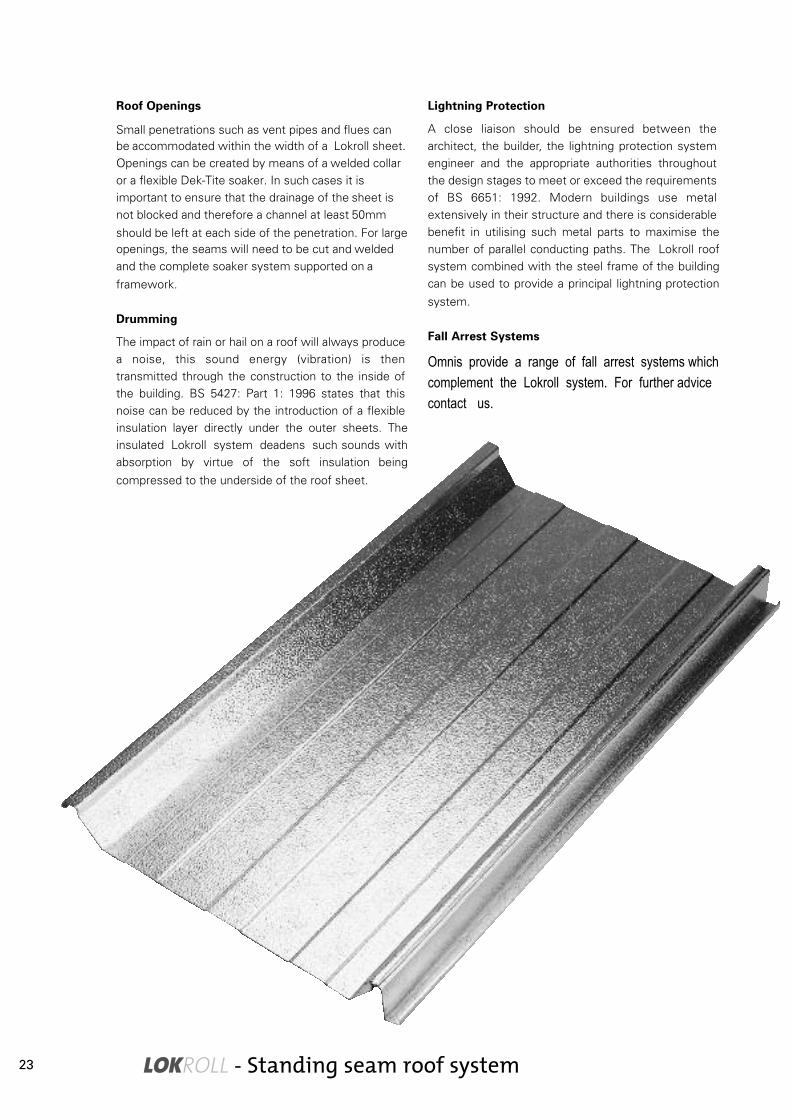
Roof Openings
Small penetrations such as vent pipes and flues can be accommodated within the width of a Lokroll sheet. Openings can be created by means of a welded collar or a flexible Dek-Tite soaker. In such cases it is important to ensure that the drainage of the sheet is not blocked and therefore a channel at least 50mm
should be left at each side of the penetration. For large openings, the seams will need to be cut and welded and the complete soaker system supported on a
framework.
Drumming
The impact of rain or hail on a roof will always produce a noise, this sound energy (vibration) is then transmitted through the construction to the inside of the building. BS 5427: Part 1: 1996 states that this noise can be reduced by the introduction of a flexible insulation layer directly under the outer sheets. The insulated Lokroll system deadens such sounds with absorption by virtue of the soft insulation being
compressed to the underside of the roof sheet.
Lightning Protection
A close liaison should be ensured between the architect, the builder, the lightning protection system engineer and the appropriate authorities throughout the design stages to meet or exceed the requirements of BS 6651: 1992. Modern buildings use metal extensively in their structure and there is considerable benefit in utilising such metal parts to maximise the number of parallel conducting paths. The Lokroll roof
system combined with the steel frame of the building
can be used to provide a principal lightning protection
system.
Fall Arrest Systems
Omnis provide a range of fall arrest systems which complement the Lokroll system. For further advice contact us.
23

Colour Coated Steel – Inspection & Maintenance RecommendationsMaintenance
Inspection is based on good practice and should be carried out annually throughout the life of the building. An inspection record should be maintained.
Proper and regular maintenance of coated metal claddings will considerably extend their functional life. Planned inspections, commencing shortly after installation, will ensure that any remedial action can be carried out before the problem becomes too serious.
As claddings are exposed to the elements, and in particular sunlight, the anticipated repaint decision varies with the colour chosen. The lighter colours absorb less ultra-violet than darker colours and hence will deteriorate less. Watch for changes in conditions of the coating particularly when the re-paint decision time approaches.
Check for:
• Blockages in gutters
• Debris
• Dirt where cladding is not naturally cleared by
rainwater
• Mould growth in extreme conditions
• Damage to the coating which can cause substrate
corrosion
• Swarf, rivet stems and any other items which can
rust
• Conditions of fasteners
• Cut edge corrosion
Cleaning
To prolong the lifetime of the cladding it should be cleaned as part of the general maintenance procedure, the following should be carried out:
• All blockages must be removed and cleaned from
gutters.
• Remove any debris from cladding that may result in
corrosion.
• Wash down and clean dirt infected areas.
• Washing may be carried out with a hose and soft
bristle brush.
• If necessary a good quality household detergent or
proprietary cleaner may be applied, following
manufacturers recommendations.
• Always rinse with clean water.
• Always wash from top to bottom.
• Do not use organic solvents or abrasive cleaners.
• Prior to cleaning remove tar or similar substances
with mineral spirit.
• Any coating damage should be treated and a touch-
up paint applied.
• A suitable treatment should be applied to any
corroded cut edges and then sprayed with a
protective lacquer.
• High-pressure water jets are not recommended, as
mastic or fillers could be dislodged, leading to other
problems.
Scratches to Surface of the Sheet
Clean the area around the damage and check for damage to the galvanised layer. If the damage is limited to the coating only, lightly abrade the area, degrease and repair with a proprietary paint or paste.
If the galvanised surface is damaged, then the area of the damage, plus approx. 20mm all round, should be rubbed with a fine wire brush or medium emery cloth, to remove all traces of rust. The area should be thoroughly cleaned, degreased and a ‘cold galvanising’ paint applied. When dry, a suitable primer and finishing paint should be applied.
Sheet Edge Peel
Sometimes the cut edge of Plastisol coated sheets shows signs of delamination (edge peel) well in advance of the anticipated life of the sheet. This will usually be limited to 5-10mm from the sheet end, and it is therefore not detrimental to the performance of the sheet. When first noticed, the loose Plastisol should be removed and repair carried out, ensuring that the coating covers at least the damaged area plus 20mm. Cutting sheets with the correct, sharp tools will minimise the likelihood of peel.
24
LOKROLL - Standing seam roof system
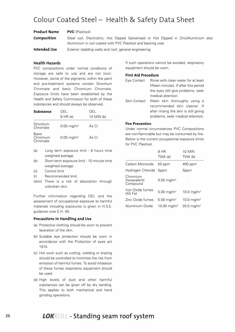
Colour Coated Steel – Health & Safety Data SheetProduct Name PVC (Plastisol)
Composition Steel coil; Electrozinc; Hot Dipped Galvanised or Hot Dipped in Zinc/Aluminium also
Aluminium in coil coated with PVC Plastisol and backing coat
Intended Use Exterior cladding walls and roof, general engineering
Health HazardsPVC compositions under normal conditions of
storage are safe to use and are not toxic.
However, some of the pigments within the paint
and pre-treatment systems contain Strontium
Chromate and basic Chromium Chromate.
Exposure limits have been established by the
Health and Safety Commission for both of these
substances and should always be observed.
Substance OEL OEL
8 HR (a) 10 MIN (b)
StrontiumChromate 0.05 mg/m3 As Cr
BasicChromium 0.05 mg/m3 As CrChromate
(a) Long term exposure limit - 8 hours time
weighted average.
(b) Short term exposure limit - 10 minute time
weighted average.
(c) Control limit
(r) Recommended limit
(skin) There is a risk of absorption through
unbroken skin.
Further information regarding OEL and the
assessment of occupational exposure to harmful
materials including exposures is given in H.S.E.
guidance note E.H. 40.
Precautions in Handling and Use(a) Protective clothing should be worn to prevent
laceration of the skin.
(b) Suitable eye protection should be worn in
accordance with the Protection of eyes act
1974.
(c) Hot work such as cutting, welding or brazing
should be controlled to minimise the risk from
emission of harmful fumes. To avoid inhalation
of these fumes respiratory equipment should
be used.
(d) High levels of dust and other harmful
substances can be given off by dry sanding.
This applies to both mechanical and hand
grinding operations.
If such operations cannot be avoided, respiratory
equipment should be worn.
First Aid ProcedureEye Contact Rinse with clean water for at least
fifteen minutes. If after this period
the eyes still give problems, seek
medical attention.
Skin Contact Wash skin thoroughly using a
recommended skin cleaner. If
after rinsing the skin is still giving
problems, seek medical attention.
Fire PreventionUnder normal circumstances PVC Compositions
are non-flammable but may be consumed by fire.
Below is the current occupational exposure limits
for PVC Plastisol.
8 HR 10 MIN
TWA (a) TWA (b)
Carbon Monoxide 50 ppm 400 ppm
Hydrogen Chloride 5ppm 5ppm
Chromium(hexavalent) 0.05 mg/m3 –
Compound
Iron Oxide fumes(AS Fe) 5.00 mg/m3 10.0 mg/m3
Zinc Oxide fumes 5.00 mg/m3 10.0 mg/m3
Aluminium Oxide 10.00 mg/m3 20.0 mg/m3
25

Steel – Health & Safety Data SheetFire ServiceIn the event of a fire appropriate respiratory apparatus should be used to avoid contact with fumes.
This health and safety data has been compiled using the following guidance.
• Toxic Substances – A Precautionary Policy EH18
• Occupational Exposure Limits 1984 EH40
• Monitoring Strategies for Toxic Substances EH42
• Carbon Monoxide EH43
• Dust in the Work Place, General principles of Protection EH44
• Protection Eye regulations 1974:S1 1681 HMSO
• Guidance Note EH44 – Dust in the Workplace: (With amendments) HMSO
• Respirators for protection against harmful dust, gases and Scheduled agricultural chem
– BS2091: 1969 (with amendments) BSI
• Specification for Filtering Facepiece dust respirators – BS6016: 1980 BSI
• Recommendations for the selection, use and maintenance of Respiratory protective
equipment BS4275: 1974 BSI
• DHSS Special Security Act 1975 CM37 – Report by the Industrial Injuries Advisory Council
on the question whether Lung cancer in workers in certain occupations should be
Prescribed under the Act April 1986 HMSO
• Exposure Limits (latest annual editions) HMSO
• Guidelines on the safe handling of Chromate Pigments and Chromate – containing paints. PMA
26

LOKROLL - Standing seam roof system
Steel – Health & Safety Data SheetProduct Name Fluorocarbon (PVF2)
Composition Steel coil; Electrozinc; Hot Dipped Galvanised or Hot Dipped in Zinc/Aluminium also
Aluminium in coil coated with Fluorocarbon (PVF2) and backing coat
Intended Use Exterior cladding walls and roof, general engineering
Health HazardsUnder normal conditions of storage PVF2 is not
toxic, however, one should avoid exposure of the
coated sheet or coil to naked flames, welding or
disc grinding. This will give off fumes and may
cause respiratory irritation, irritation of the skin,
chest, tightness and coughing, which may persist
for a few days after exposure. The main entry into
the body of these decomposition by-products is
by inhalation and one should avoid inhalation of
fume at any time.
Pigments within the pre-treatment and primer
systems contain Strontium Chromate and basic
Chromium Chromate. These two substances are
listed below for which occupational exposure
limits have been established by the Health and
Safety commission.
Substance OEL OEL
8 HR (a) 10 MIN (b)
StrontiumChromate 0.05 mg/m3 As Cr
BasicChromium 0.05 mg/m3 As CrChromate
(a) Long term exposure limit - 8 hours time
weighted average.
(b) Short term exposure limit - 10 minute time
weighted average.
(c) Control limit
(r) Recommended limit
(skin) There is a risk of absorption through
unbroken skin.
Further information regarding OEL and the
assessment of occupational exposure to harmful
materials including exposures is given in H.S.E.
guidance note E.H. 40.
Precautions in Handling and Use(a) Protective clothing should be worn to prevent
laceration of the skin.
(b) Suitable eye protection should be worn in
accordance with the Protection of eyes act
1974.
(c) Hot work such as cutting, welding or brazing
should be controlled to minimise the risk from
emission of harmful fumes. To avoid inhalation
of these fumes respiratory equipment should
be used.
(d) High levels of dust and other harmful
substances can be given off by dry sanding.
This applies to both mechanical and hand
grinding operations.
If such operations cannot be avoided, respiratory
equipment should be worn.
First Aid ProcedureEye Contact Rinse with clean water for at least
fifteen minutes. If after this period
the eyes still give problems, seek
medical attention.
Skin Contact Wash skin thoroughly using a
recommended skin cleaner. If
after rinsing the skin is still giving
problems, seek medical attention.
Fire PreventionUnder normal circumstances Fluorocarbon (PVF2)
compositions are non-flammable but may be
consumed by fire. Below is the current
occupational exposure limits for Fluorocarbons.
8 HR 10 MIN
TWA (a) TWA (b)
Iron Oxide fumes(AS Fe) 5.00 mg/m3 10.0 mg/m3
Zinc Oxide fumes 5.00 mg/m3 10.0 mg/m3
Chromium(hexavalent) 0.05 mg/m3 –
Compound
Carbon Monoxide 50 ppm 400 ppm
Hydrogen Fluoride 3 ppm 6 ppm
Epichlorohydrin 2 ppm 5 ppm
Aluminium Oxide 10 ppm 20 ppm
Fire ServiceIn the event of a fire appropriate respiratory
apparatus should be used to avoid contact with
fumes.
27

Steel – Health & Safety Data SheetProduct Name Polyester
Composition Steel coil; Electrozinc; Hot Dipped Galvanised or Hot Dipped in Zinc/Aluminium also
Aluminium in coil coated with Polyester and grey backing coat
Intended Use Exterior cladding walls and roof, general engineering
Health HazardsPolyester compositions under normal conditions
are not toxic. Pigments within the pre-treatment
and primer systems contain Strontium Chromate
and basic Chromium Chromate. Exposure limits
have been established by the Health and safety
commission for both of these substances and
should always be observed.
Substance OEL OEL
8 HR (a) 10 MIN (b)
StrontiumChromate 0.05 mg/m3 As Cr
BasicChromium 0.05 mg/m3 As CrChromate
(a) Long term exposure limit - 8 hours time
weighted average.
(b) Short term exposure limit - 10 minute time
weighted average.
(c) Control limit
(r) Recommended limit
(skin) There is a risk of absorption through
unbroken skin.
Further information regarding OEL and the
assessment of occupational exposure to harmful
materials including exposures is given in H.S.E.
guidance note E.H. 40.
Precautions in Handling and Use(a) Protective clothing should be worn to prevent
laceration of the skin.
(b) Suitable eye protection should be worn in
accordance with the Protection of eyes act
1974.
(c) Hot work such as cutting, welding or brazing
should be controlled to minimise the risk from
emission of harmful fumes. To avoid inhalation
of these fumes respiratory equipment should
be used.
(d) High levels of dust and other harmful
substances can be given off by dry sanding.
This applies to both mechanical and hand
grinding operations.
If such operations cannot be avoided, respiratory
equipment should be worn.
First Aid ProcedureEye Contact Rinse with clean water for at least
fifteen minutes. If after this period
the eyes still give problems, seek
medical attention.
Skin Contact Wash skin thoroughly using a
recommended skin cleaner. If
after rinsing the skin is still giving
problems, seek medical attention.
Fire PreventionUnder normal circumstances Polyester
compositions are non-flammable but may be
consumed by fire. Below is the current
occupational exposure limits for Polyester.
8 HR 10 MIN
TWA (a) TWA (b)
Carbon Monoxide 50 ppm 400 ppm
Hydrogen Chloride 5ppm 5ppm
Chromium(hexavalent) 0.05 mg/m3 –
Compound
Iron Oxide fumes(AS Fe) 5.00 mg/m3 10.0 mg/m3
Zinc Oxide fumes 5.00 mg/m3 10.0 mg/m3
Aluminium Oxide 10.00 mg/m3 20.0 mg/m3
Fire ServiceIn the event of a fire appropriate respiratory
apparatus should be used to avoid contact with
fumes.
28

LOKROLL - Standing seam roof system
Steel – Site SafetySteel is not hazardous nor an injurious substance. It isnot combustible and does not emit toxic fumes and isductile at all normal operating temperatures (it will notshatter or crack). All normal mandatory Health & SafetyRegulations must be followed. The precautions beloware particularly applicable to working with standingseam sheets.
• Gloves should be worn when handling metalsheets
• Eye protection should always be worn duringcutting and drilling operations
• In windy conditions all unfixed, or partially fixedsheets and flashings must be adequately securedto ensure they are not dislodged and become ahazard to people and property. In addition, it may bedangerous to carry materials in such conditions,especially when working above ground level
• Lokroll sheets must NEVER be used as a workingsurface during construction, unless they are fullyfixed in strict accordance with ourrecommendations. Otherwise separate, securedstaging must be provided for site personnel
• Individual sheets must be seamed as soon as theyare in place, for safety reasons and to offerprotection to the insulation from rain
• At the end of a fixing run the last sheet should betemporarily secured using pressed verge clipsscrewed to the halter brackets
• To avoid localised deformations of the pan of thesheet it is recommended that only the upstands ofthe seams should be walked on
• Boards and roof ladders are always preferred ratherthan walking directly on the sheets
• Non-roofing trades should be provided withwalkways when access across a sheeted roof isrequired
• Where sheets are to be stacked on the roof, theymust only be placed over a main frame and be wellsecured when not being used. Care should betaken to avoid over-loading the structure andpermission of the Structural Engineer must besought beforehand.
OpeningsUse cones and tapes to indicate roof openings
awaiting roof lights, hatches and protrusions etc.
29

• Store stacks off the ground and on a slope so that,
should rain penetrate the covering, the water will
drain away
• Inspect the storage site regularly to ensure that
moisture, despite the above precautions, has not
penetrated the stack
• Care should be taken to avoid condensation
staining between the sheets
• Do not store sheets where people will walk across
them
Handling Individual Sheets
Single sheets are relatively light, but long sheets can be difficult to handle in windy conditions Sheets up to about 14 metres long can usually be handled by two operatives. A third operative is required for sheets up 21 metres, and a fourth for sheets up to about 28 metres. These are approximate figures, and may need amendment in windy weather, or on roofs with difficult access. Sheets should be carried on their side.
After the works have been completed all damaged and waste materials (including packaging) should be disposed of in accordance with appropriate Health and Safety Regulations.
Steel – Site Safety, Handling & StorageOff-Loading
Lokroll is delivered to site in packs which can weigh up to about 3 tonnes. Packs up to 10 metres long may be off-loaded by forklift truck; cranes are needed for greater lengths. The crane should lift by means of nylon slings (never chains) and the pack should never project more than 4 metres beyond the last sling. Slings should never be more than 6 metres apart, and for long packs it is essential to use spreader
beams.
This general advice is offered for guidance only. Each lift needs to be done by appropriately trained personnel using the correct and serviceable equipment.
Storage
A suitable site for storage should be selected to avoid unnecessary handling of sheets and or components and the following precautions strictly adhered to:
• Do not leave uncovered stacks lying in the open,
store under cover and away from open doorways
• If stacks cannot be kept under cover, erect simple
scaffolding around them and cover with a
waterproof sheet, tarpaulin or polythene. Leave
space between cover and sheets to allow air to
circulate
30

LOKROLL - Standing seam roof system
MaintenanceMill finish aluminium does not require maintenance to
restore its appearance, it is normally accepted in its
weather condition.
Coated finishes do not require any special
maintenance, although washing with clean water or a
sugar soap solution may be advantageous in dusty or
industrial areas.
Roofs should be given periodic inspections and the
accumulation of debris, falling leaves, etc. should be
removed before it can block drainage and promote
corrosion. Damaged sheets or flashings should be
removed and replaced at the earliest opportunity, to
minimise damage due to ingress of storm water.
Maintenance and cleaning personnel must use
scaffold boards on all roofs. Always provide load-
spreading measures at the ridge and at the eaves in
order to avoid local deformations from excessive foot
traffic especially at the point of access to the roof.
Aluminium sheets must be isolated from any other
materials that may cause galvanic corrosion. Any
contamination or exposure to corrosive materials must
be removed. Any moisture trapped in the construction
must be removed.
CleaningUpon completion of each section of the roof it should
be thoroughly cleaned to remove all swarf, rivet
mandrels, screws, washers, rivets etc. Any of these
items could cause unsightly rust stains. Cement or
mortar droppings should be removed immediately or
they will leave permanent stains. Marks from oil,
grease etc should be removed by washing with a mild
detergent, remembering to rinse thoroughly with clean
water.
Sometimes coated sheets are protected by a thin
plastic film, which must be removed immediately after
fixing. Long exposure to ultra violet light can harden
the film and make it difficult to remove, leaving sticky
deposits which collect dirt and spoil the appearance of
the roof. Should adhesive marks remain, these can be
removed by using BT8 Thinner (SBP6 Solvent)
available from SG Bailey Paints Ltd.
It is recommended that periodical inspections should
be made for damage. Should debris be causing
obstructions, it should be removed and the area
washed down with a mild detergent and rinsed
thoroughly with clean water. In some areas
(particularly industrial ones and where cladding is sheltered directly below a soffit) it may be necessary to clean the installation periodically to restore its appearance to remove corrosive deposits. This can be carried out by hosing with water using a neutral detergent.
Colour-Coated SurfacesUse special non-abrasive, biologically degradable cleaner compatible with the coating system and rinse thoroughly after cleaning. It is often worthwhile waiting, since weathering and dirt accumulation will reduce colour differences. This process will be faster on a natural finish surface than on coloured material.
Removing Dirt
Use an abrasive agent with a pH value of between 5 and 8. When using special cleaning agents, make sure that they are ecologically compatible. Always rinse off with water.
Repairs to Painted SurfacesIn the case of aluminium, minor scratches and abrasions do not require repairs, except where the scratches become visually unacceptable. However, it should be noted that site repairs on scratches can not always be justified on aesthetic grounds as the repaint is usually more prominent than the scratch. Air drying paints will never be a perfect match for factory stoved paints, the gloss levels will probably differ and they will certainly age differently. Larger areas of damage
must be site painted to disguise unsightly patches or exposed metal. In these cases the damaged areas should be cleaned and painted with an approved touch up paint to match the sheet finish.
In all cases, small areas should be painted using a small soft artists brush. 'Daubing' with a decorator's brush will never be successful.
When painting over coated areas, preparatory measures and type of coating must be coordinated with the existing paint system on the advice of a paint specialist. PVF2 coated sheets should only be touched up with air drying PVF2 paint such as DURANAR ADS. Trained specialists can only apply this paint system. Use the standard air drying touch up paint provided.
Aluminium - Inspection & Maintenance Recommendations
31

For minor scratches and small repairs apply the paint
provided sparingly using a pencil brush in two coats,
allowing 15 minutes between coats. The paint should
be touch dry in 30 minutes. Do not paint in damp
conditions or when rainfall or condensation is
expected within 2 hours. Only paint when the
temperature range is within 5 - 30°C. Care must be
taken to comply with Health & Safety Regulations as
recommended by the paint and solvent
manufacturers.
Repairs Of Minor Damage Preparation - Weathered material
Clean the area to be painted with a mild detergent
solution and rinse with clean water, then thoroughly
dry off with a clean cloth. If surface damage has
occurred, prepare the area with fine wet and dry paper
taking care to feather in the edges to the original
surface. After final preparation, de-dust the area using
a lint free cloth or a proprietary tack rag.
New material Wipe the immediate area to be painted with a clean
cloth moderately soaked with an industrial safe solvent
e.g. Panel Wipe. When the solvent has flashed off,
wipe the area again with clean lint free cloth. If primer
has been used to cover any areas of bare metal, lightly
flat the surface using 400-grade wet and dry paper,
finally de-dust the area using a lint free cloth or a
proprietary tack rag.
Paint Suppliers
S G Bailey Paints Ltd
Griffin Mill Estate
London Road
Thrupp
Stroud
Gloucestershire
GL5 2AZ
Tel: 01453 882237
PPG Industries UK Ltd
Building Products Division
PO Box 359
Rotton Park Street
Ladywood
Birmingham
B16 OAD
Tel: 0121 4559866
Aluminium - Inspection & Maintenance Recommendations
pH
Strong StrongWeak WeakNeutral
ACIDS
THE pH SCALE
ALKALIS
1 2 3 4 5 6 8 9 10 11 12 13 147
32

LOKROLL - Standing seam roof system
Product Name Mill Finish Aluminium
Composition Aluminium Alloy, in sheet, plate or coil form
Intended Use Exterior cladding walls and roof, general engineering
Health HazardsWhen handling the product in sheet or coil form, there
is a risk of laceration of the skin, inhalation of
aluminium dust may cause shortness of breath and
aggravate bronchial conditions. Occupational Exposure
Limits have been established for aluminium dust by
the Health and Safety Commission. This limit is
detailed below O.E.L. should always be observed.
Substance OEL OEL
8 HR (a) 10 MIN (b) Notes
Aluminium 10 mg/m3 20 mg/m3 as dust
(a) Long term exposure limit - 8 hour time
weighted average.
(b) Short term exposure limit - 10 minute time
weighted average.
(s) Occupational Standard Limit.
(m) Maximum Exposure Limit
(c) Manufacturers Data
(d) Limits in mg/m3, all other data in parts per
million ppm.
(skin) There is a risk of absorption through unbroken
skin.
Further guidance on OEL and the assessment of
occupational exposure to harmful materials including
mixed exposures, is given in HSE guidance note EH40.
Precautions in Handling and UseProtective clothing should be worn to prevent
laceration of the skin. Avoid inhalation of dust, this
should be achieved by the use of local exhaust
ventilation and good general ventilation. If this is not
sufficient to maintain concentrations of dust particles
at a level below the OEL, suitable respiratory
protection must be worn.
First Aid ProcedureEye Contact Irrigate copiously with clean fresh
water, holding the eyelids apart.
Skin Contact Wash skin thoroughly with soap and
water or use a proprietary skin cleaner.
Fire PreventionIn plate, sheet or coil form, material does not burn. In
powder or chip form, use dry powder
or sand. Do not use water or halogen extinguishing
agent.
Unusual Fire HazardsWater, oxidisers and many other chemicals react
explosively in contact with molten aluminium fine
chips, turnings and dust in air may explode if ignition
source is present.
Relevant Referencesa) H.S.E. Guidance NotesEH18: Toxic Substances - a Precautionary Policy
EH40: Occupational Exposure Limits 1991
EH42: Monitoring Strategies for Toxic Substances
EH43: Carbon Monoxide
EH44: Dust in the Work Place, General Principals of
Protection
Aluminium – Health & Safety Data Sheet
33

Aluminium – Health & Safety Data Sheet
First Aid ProcedureEye Contact Irrigate copiously with clean fresh
water for at least ten minutes, holdingthe eyelids apart.
Skin Contact Wash skin thoroughly with soap andwater or use a proprietary skin cleaner.
Fire PreventionUnder normal conditions of storage and use, Polyestercompositions are not flammable but may be consumedby fire. The major productsof combustion/decomposition of Polyestercomposition are detailed below.
Current Occupational Exposure Limits
8 HR 10 MIN(Products ofCombustion) TWA (a) TWA (b) Notes
Chromium(Hexavalent) 0.05 mg/m3 As CrCompounds
Carbon Monoxide 50 ppm 300 ppm
Aluminium Oxide 10 ppm 20 ppm
Lead Oxide 0.15 mg/m3 -
Relevant Referencesa) H.S.E. Guidance NotesEH 18: Toxic Substances - a Precautionary Policy
EH 40: Occupational Exposure Limits 1991
EH 42: Monitoring Strategies for Toxic Substances
EH 43: Carbon Monoxide
EH 44: Dust in the Work Place, General Principals ofProtection.
Product Name Organic Coatings: Polyester and ARS (Polyurethane based)
Composition Aluminium Alloy, Sheet or coil coated with a Primer, Polyester top coat and backing coat.
The Organic top coat is typically between 1.15% and 3.69% by weight of product
Intended Use Exterior cladding walls and roof, general engineering
Health HazardsWhen handling the product in sheet or coil form there
is a risk of laceration of the skin. Polyester
compositions under normal conditions are not toxic.
Pigments within the pre-treatment and paint systems
may contain one or more of
the substances listed below. The Health
and Safety Commission have established occupational
exposure limits, these limits should always be
observed.
Substance OEL OEL
8 HR (a) 10 MIN (b) Notes
BasicChromium 0.05 mg/m3 - As CrChromate
Aluminium 10 ppm 20 ppm
LeadChromate 0.15 mg/m3 -Pigment
(a) Long term exposure limit - 8 hour time
weighted average
(b) Short term exposure limit - 10 minute time
weighted average.
(s) Occupational Standard Limit.
(m) Maximum Exposure Limit.
(c) Manufacturers Data.
(d) Limits in mg/m3, all other data in parts per
million ppm.
(Skin) There is a risk of absorption through unbroken
skin.
Further guidance on OEL and the assessment ofoccupational exposure to harmful materials includingmixed exposures, is given in HSE guidance note EH40.
Precautions in Handling and UseProtective clothing should be worn to preventlaceration of the skin. Avoid inhalation of dust. Thisshould be achieved by the use of local exhaustventilation and good general ventilation. If this is notsufficient to maintain concentrations of dust particlesat a level below the OEL, suitable respiratoryprotection must be worn.
34

LOKROLL - Standing seam roof system
Aluminium – Health & Safety Data SheetProduct Name Organic Coating: Fluorocarbon (PVF2) based
Composition Aluminium Alloy, sheet or coil coated with Epoxy or Acrylic Primer, Fluorocarbon top coat and
a backing coat. The Fluorocarbon Organic top coat is typically between 1.15% and 3.69% by
weight of product
Intended Use Exterior cladding walls and roof, general engineering
Health HazardsWhen handling the product in sheet or coil form there
is a risk of laceration of the skin. Fluoroplastics are
extremely inert biologically and hazards are only likely
to occur with decomposition by heat. The composition
of thermal decomposition products is not well defined.
The condition resulting from exposure to these
products is known as Polymer Fume Fever. This is a
temporary influenza-like condition that appears some 4
to 5 hours after exposure to sublimates or thermal
decomposition of Fluoroplastics.
The temperature of burning tobacco or equivalent heat
is sufficient to produce the physical Pyrolytic changes
in the otherwise inert Polymer. Respiratory irritation
may occur. The acute illness may be alarming and
uncomfortable when it is severe, but it is short in
duration and without known long-term ill effects.
When subjected to elevated temperatures e.g., during
welding, flame cutting, sawing, machining and other
mechanical work of the solid cured resins, fumes may
be produced containing thermal decomposition
products of the resin e.g., Amines and/or unreacted
Epichlorohydrin. These products can be irritating to the
skin and to the respiratory tract where they may cause
chest tightness and episodes of coughing which may
persist for a few days after exposure.
The principal mode of entry into the body of these
decomposition products is by inhalation and their
inhalation should be prevented. Fluorocarbon (PVF2)
under normal conditions of storage is not toxic.
Pigments within the pre-treatment and paint systems
may contain one or more of the substances listed
below. The Health and Safety Commission have
established occupational Exposure Limits. These limits
should always
be observed.
Substance OEL OEL8 HR (a) 10 MIN (b) Notes
BasicChromium 0.05 mg/m3 - As CrChromate
Aluminium 10 ppm 20 ppm
Lead 0.15 mg/m3 -
(a) Long term exposure limit - 8 hour timeweighted average
(b) Short term exposure limit - 10 minute timeweighted average.
(s) Occupational Standard Limit.(m) Maximum Exposure Limit.(c) Manufacturers Data.(d) Limits in mg/m3, all other data in parts per
million ppm.(Skin) There is a risk of absorption through unbroken
skin.
Further guidance on OEL and the assessment of
occupational exposure to harmful materials including
mixed exposures, is given in HSE guidance note EH40.
Precautions in Handling and UseProtective clothing should be worn to prevent
laceration of the skin. Avoid inhalation of dust. This
should be achieved by the use of local exhaust
ventilation and good general ventilation. If this is not
sufficient to maintain concentrations of dust particles
at a level below the OEL, suitable respiratory
protection must be worn.
First Aid ProcedureEye Contact Irrigate copiously with clean fresh
water for at least ten minutes, holding
the eyelids apart.
Skin Contact Wash skin thoroughly with soap and
water or use a proprietary skin cleaner.
35

Aluminium – Health & Safety Data Sheet
Fire PreventionUnder normal conditions of storage and use,
Fluorocarbon compositions are not flammable but may
be consumed by fire. The major products
of combustion/decomposition of Fluorocarbon
composition are detailed below.
Current Occupational Exposure Limits
8 HR 10 MIN(Products ofCombustion) TWA (a) TWA (b) Notes
Chromium(Hexavalent) 0.05 mg/m3 As CrCompounds
Epichlorohydrin 2 ppm 5 ppm
Aluminium Oxide 10 ppm 20 ppm
Lead Oxide 0.15 mg/m3 -
In the event of fire, appropriate respiratory
protective equipment should be used by fire fighters.
Relevant Referencesa) H.S.E. Guidance NotesEH 18: Toxic Substances - a Precautionary Policy
EH 40: Occupational Exposure Limits 1991
EH 42: Monitoring Strategies for Toxic Substances
EH 43: Carbon Monoxide
EH 44: Dust in the Work Place, General Principals of
Protection.
36

LOKROLL - Standing seam roof system
Aluminium - Site SafetyAluminium is not hazardous nor an injurious
substance. It is not combustible and does not emit
toxic fumes and is ductile at all normal operating
temperatures (it will not shatter or crack). All normal
mandatory Health & Safety Regulations must be
followed. The precautions below are particularly
applicable to working with standing seam sheets.
� Gloves should be worn when handling metal sheets
� Eye protection should always be worn during cutting
and drilling operations
� In windy conditions all unfixed, or partially fixed
sheets and flashings must be adequately secured to
ensure they are not dislodged and become a hazard to
people and property. In addition, it may be dangerous
to carry materials in such conditions, especially when
working above ground level
� Lokroll sheets must NEVER be used as a working
surface during construction, unless they are fully fixed
in strict accordance with our recommendations.
Otherwise separate, secured staging must be
provided for site personnel
� Individual sheets must be fixed as soon as they are
in place, for safety reasons and to offer protection to
the insulation from rain
� At the end of a fixing run the last sheet should be
temporarily secured using pressed verge clips screwed
to the halter brackets
� To avoid localised deformations of the pan of the
sheet it is recommended that only the upstands of the
seams should be walked on
� Boards and roof ladders are always preferred rather
than walking directly on the sheets
�Non-roofing trades should be provided with
walkways when access across a sheeted roof is
required
� Where sheets are to be stacked on the roof, they
must only be placed over a main frame and be well
secured when not being used. Care should be taken to
avoid over-loading the structure and permission of the
Structural Engineer must be sought beforehand.
OpeningsUse cones and tapes to indicate roof openings awaited
roof lights, hatches and protrusions etc.
Aluminium – Site Safety
37

Off-LoadingLokroll is delivered to site in packs which can weigh up
to about 3 tonnes. Packs up to 10 metres long may be
off-loaded by forklift truck; cranes are needed for
greater lengths. The crane should lift by means
of.nylon slings (never chains) and the pack should
never project more than 4 metres beyond the last
sling. Slings should never be more than 6 metres
apart, and for long packs it is essential to use spreader
beams.
This general advice is offered for guidance only. Each
lift needs to be done by appropriately trained
personnel using the correct and serviceable
equipment. RigiSystems strongly recommend the use
of specialist lifting companies who should be given full
responsibility for the safe offloading of the product.
StorageA suitable site for storage should be selected to avoid
unnecessary handling of sheets and or components
and the following precautions strictly adhered to:
• Do not leave uncovered stacks lying in the open,
store under cover and away from open doorways
• If stacks cannot be kept under cover, erect simple
scaffolding around them and cover with a
waterproof sheet, tarpaulin or polythene. Leave
space between cover and sheets to allow air to
circulate
• Store stacks off the ground and on a slope so that,
should rain penetrate the covering, the water will
drain away
• Inspect the storage site regularly to ensure that
moisture, despite the above precautions, has not
penetrated the stack
• Care should be taken to avoid condensation
staining between the sheets
• Do not store sheets where people will walk across
them
Handling Individual SheetsSingle sheets are relatively light, but long sheets can
be difficult to handle in windy conditions. Sheets up to
about 14 metres long can usually be handled by two
operatives. A third operative is required for sheets up
21 metres, and a fourth for sheets up to about 28
metres. These are approximate figures, and may need
amendment in windy weather, or on roofs with difficult
access. Sheets should be carried on their side.
After the works have been completed all damaged and
waste materials (including packaging) should be
disposed of in accordance with appropriate Health and
Safety Regulations and in accordance with
Environment Agency guidelines.
Aluminium – Site Safety, Handling & Storage
38

LOKROLL - Standing seam roof system
End LapsThe RigiSystems Lokroll cladding system has been
designed to provide a single sheet length running from
ridge to eaves.
Long lengths can be end lapped on site by cutting the
rib or standing seam.
End laps are required where:
� Large vents or ducting penetrate the RigiSystems
Lokroll, requiring a larger soaker
� Rooflights are positioned at mid slope, requiring a
soaker
� There is restricted access on site t handling long
sheet lengths
� The overall roof slope exceeds the maximum sheet
length
� There is a restriction in headroom, preventing the
RigiSystems Lokroll sheets being rotated and roll
locked into position.
End laps should be positioned upslope from a purlin at
approximately 150mm with a minimum overlap of
200mm.
For a pitch greater than 5° the overlap joint must be
fixed with Bulbtite rivets and sealed with Silka flex IIFC
sealant. For a more secure overlap and any pitch below
5° site welding will ensure that there are no
penetrations of the external weathering skin.
Miscellaneous
Bulbtite Rivets
39

Installation – Measurement & Setting OutSetting Out LineThe roofing drawings should show the datum for setting out; this will usually relate to a frame, rafter, wall, or prominent feature. It is important that the Lokroll sheets are set out correctly relative to the setting out line, otherwise verge flashings may not fit, openings could be in the wrong place, etc.
Setting Out The BracketsUsing two fasteners into light gauge purlins, the bracket support and fastener assembly has a proven minimum safe working load of 3kN. To calculate the maximum centres of the brackets along the support bar the main purlin centres in metres (M) is required along wit the design wind uplift loading in kN/m_ (W). The following formula is then applied:
Maximum bracket = 3
spacing
M x W
For example purlins at 2 metre centres with a design
wind uplift loading of 1.4 kN/m_:
Maximum bracket = 3
spacing = 1.07 metres
2 x 1.4
The brackets should be fixed at convenient centres
below the calculated maximum e.g. 1-metre spacings.
Installing The Bar & Bracket SystemFollowing the installation of the liner sheet and
continuous vapour control layer the brackets are fixed
in place at the predetermined centres using standard
self-drilling fasteners. For steel purlins up to 3.5mm
thick the use of Corofix® Topex 14 self-drill screws are
recommended and Corofix® Topex-24 fasteners for
hot rolled sections.
For refurbishment applications the use of Corofix®
Topex High Thread fasteners is recommended to
provide firm independent support and maximum
stability. To prevent damage to the existing structure
the pre-drilling of 5.8mm diameter clearance holes is
advised.
A requirement of new Building Regulations is to
achieve an insulation layer that is ‘reasonably
continuous’ over the building envelope. With mineral
fibre insulation it is essential that all edges are closely
butted together and that there are no gaps or holes.
When the Corogrid brackets are fixed in place install the first layer of insulation with staggered butted joints taking care to ensure the insulation layer is continuous and without any gaps. Due to the unique way the Corogrid system is fixed (i.e. the brackets are fixed prior to the application of the support bar) the continuity of the insulation is maintained.
When the brackets are fixed in place, the support bar is simply rotated into a secure position at 90° to the brackets. A bracket should always be positioned within 75mm from the leading end of a support bar so that the joint is not subject to bending.
The second layer of insulation is installed over the Corogrid bar and bracket system again with staggered butted joints to ensure a continuous insulation layer is created.
Note: Template required for correct fixing, see page 2
40
The Eaves Setting Out Line
The drawings should show the intended position of the end of the sheets at the eaves. On conventional roofs, it is usually best to set out a string line at the eaves and set out the sheets from that line. Any tolerance in the sheet lengths will then be hidden under the ridge flashing.
However some roofs, such as barrel vaults and bowed ridges, have two eaves lines and no ridge flashing. In these cases a string line is still helpful as a guide, but any discrepancy in length is best shared between the two sides. The tolerance in the length of a Lokroll sheet is quite small.

LOKROLL - Standing seam roof system
Installation – Ridge DetailBecause Lokroll is installed to roof pitches as low as 1.5°, special provisions are made at vulnerable details, i.e. the ridge. The pan of the sheet is turned up using a special tool, and the profile filler is held in a metal shroud to give the filler rigidity and to protect it against degradation by ultra-violet light.
The filler assembly is located in a ridge retainer section which is rivetted to every profile crown. The flashing is attached to the ridge retainer at maximum 300mm centres.
Installation – Eaves DetailWeather ProtectionAll the rainwater which falls on the roof must eventually drain away at the eaves. It is important that this
water should discharge cleanly into the gutter and not be blown back through the seams or under the sheets. The seams are closed at the eaves by means of profiled foam filler blocks. A drip angle is used to prevent water being blown back under the roof. The profiled fillers are positioned directly over the drip angle, which in turn is rivetted to the trough of the RigiSystems Lokroll sheets with at least two rivets per sheet. These fasteners also retain the fillers. On very shallow slopes (3° or less) it is useful to turn down the ends of the sheets so that discharge is more complete and there is less risk of dirty stains forming at the end of
the sheet.
Thermal MovementOn most roofs, the fixed point is at the ridge. This means that the maximum amount of movement takes place at the eaves and due allowance must be made for this. The sheets must be long enough to discharge into the gutter at all times and the clearance behind the drip angle must be sufficient to allow unrestricted movement.
The Drip AngleThe drip angle serves two other functions. It has the aesthetic value of holding the sheets in a good straight line and it provides structural support in the event of the end of the sheet being subjected to foot traffic. The drip angle is 30mm x 60mm deep and made of 2mm thick aluminium.
41
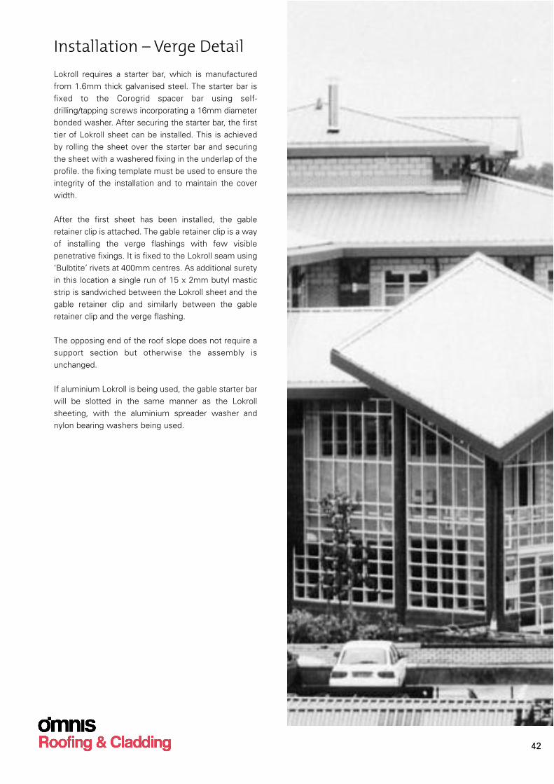
Installation – Verge DetailLokroll requires a starter bar, which is manufactured
from 1.6mm thick galvanised steel. The starter bar is
fixed to the Corogrid spacer bar using self-
drilling/tapping screws incorporating a 16mm diameter
bonded washer. After securing the starter bar, the first
tier of Lokroll sheet can be installed. This is achieved
by rolling the sheet over the starter bar and securing
the sheet with a washered fixing in the underlap of the
profile. the fixing template must be used to ensure the
integrity of the installation and to maintain the cover
width.
After the first sheet has been installed, the gable
retainer clip is attached. The gable retainer clip is a way
of installing the verge flashings with few visible
penetrative fixings. It is fixed to the Lokroll seam using
‘Bulbtite’ rivets at 400mm centres. As additional surety
in this location a single run of 15 x 2mm butyl mastic
strip is sandwiched between the Lokroll sheet and the
gable retainer clip and similarly between the gable
retainer clip and the verge flashing.
The opposing end of the roof slope does not require a
support section but otherwise the assembly is
unchanged.
If aluminium Lokroll is being used, the gable starter bar
will be slotted in the same manner as the Lokroll
sheeting, with the aluminium spreader washer and
nylon bearing washers being used.
42
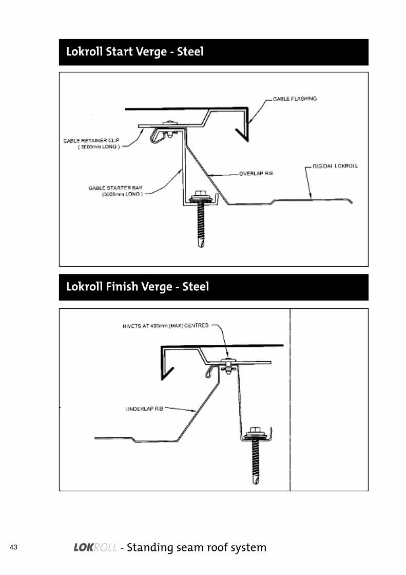
LOKROLL - Standing seam roof system
Lokroll Start Verge - Steel
Lokroll Finish Verge - Steel
43

Lokroll Start Verge - Aluminium
Lokroll Finish Verge - Aluminium
44

LOK
RO
LL - E
ND
LA
P S
YS
TEM
45

LOK
RO
LL - T
YPIC
AL
RID
GE D
ETA
IL
46

LOK
RO
LL - E
AV
ES
DETA
IL
47