r 6-1 · pdf filedkd-r 6-1 calibration of pressure gauges. ... 8.2 procedure ... annex b...
TRANSCRIPT
Edition 01/2003 Page 1 of 43
DEUTSCHER KALIBRIERDIENST
Guideline
DKD-R 6-1
Calibration of
Pressure Gauges
DKD-R 6-1 ◆ Calibration of Pressure Gauges
Edition 01/2003 Page 2 of 43
Published by the Accreditation Body of the Deutscher Kalibrierdienst (DKD) at the Physika-lisch-Technische Bundesanstalt in co-operation with its Technical Committee "Pressure andVacuum."
Copyright 2003 by DKD
The work including all its parts is protected by copyright. Any exploitation outside the narrowconfines of the Copyright Act is inadmissible and liable to prosecution unless it has been ap-proved. This is valid in particular for reproductions, translations, microfilming as well as stor-age and processing in electronic systems.
The document and all its parts are protected by copyright. Any unauthorized use outside thenarrow limits set by the Copyright Act is inadmissible and liable to prosecution. This applies inparticular to copies, translations, microfilming and storage and processing in electronic sys-tems.
Deutscher Kalibrierdienst (DKD)
The DKD comprises calibration laboratories in industrial enterprises, research institutes, tech-nical authorities, inspection and testing institutes. They are accredited and supervised by theDKD. They calibrate measuring instruments and material measures for measurands andmeasurement ranges specified within the scope of accreditation. The DKD calibration certifi-cates issued by these laboratories prove traceability to national standards as required in theISO 9000 family and ISO/IEC 17025.
Calibrations carried out by DKD laboratories ensure that the user may rely on measurementresults. They increase the customers' confidence and competitiveness on the national andinternational markets and serve as a metrological basis for the inspection of measuring andtest equipment within the framework of quality assurance measures.
Calibrations offered by the DKD cover electrical measurands, length, angles and other geo-metrical quantities, roughness, coordinate and form measuring techniques, time and fre-quency, force, torque, acceleration, pressure, flowrate, temperature, humidity, medical meas-urands, acoustic measurands, optical measurands, ionizing radiation and other measurands.
Publications: see Internet
Address:
Deutscher Kalibrierdienst at thePhysikalisch-Technische BundesanstaltBundesallee 100 D-38116 BraunschweigP.O. Box 33 45 D-38023 BraunschweigOffice telephone +49 531 592 1901Fax +49 531 592 1905E-Mail [email protected] www.dkd.info
DKD-R 6-1 ◆ Calibration of Pressure Gauges
Edition 01/2003 Page 3 of 43
Foreword
DKD Guidelines are application documents for the general criteria and procedures which arelaid down in DIN EN ISO/IEC 17025 and DKD publications. The DKD Guidelines describetechnical and organizational processes serving the calibration laboratories as a model for lay-ing down internal procedures and regulations. DKD Guidelines can become an integral part ofquality manuals of calibration laboratories. The application of the Guidelines supports equaltreatment of the devices to be calibrated at the different calibration laboratories and improvesthe continuity and verifiability of the work of the calibration laboratories.
The DKD Guidelines will not impede the further development of calibration procedures andsequences. Deviations from guidelines and new methods are permitted in agreement with theAccreditation Body if they are justified by technical aspects.
The present Guideline was prepared by the Technical Committee "Pressure and Vacuum" inco-operation with the PTB and adopted by the Advisory Board of the DKD. With its publicationit is binding for all DKD calibration laboratories unless separate procedural instructions ap-proved by the Accreditation Body are available.
Contents
1 Purpose and scope of application .......................................................................... 5
2 Symbols and designations ..................................................................................... 5
2.1 Variables ............................................................................................................... 5
2.2 Indices................................................................................................................... 7
3 Reference and working standards.......................................................................... 7
4 Calibration item ...................................................................................................... 8
5 Calibratability.......................................................................................................... 9
6 Ambient conditions................................................................................................. 9
7 Calibration methods ..............................................................................................10
8 Measurement uncertainty......................................................................................13
8.1 Definition ..............................................................................................................13
8.2 Procedure.............................................................................................................13
8.2.1 Evaluation model ..................................................................................................13
8.2.2 Sum/difference model...........................................................................................14
8.2.3 Product/quotient model.........................................................................................14
8.2.4 Input quantities .....................................................................................................15
8.2.5 Potential influence quantities, example.................................................................16
8.3 Calibration of Bourdon tube pressure gauges.......................................................17
8.3.1 Evaluation model ..................................................................................................17
8.3.2 Uncertainty analysis..............................................................................................18
8.3.3 Load step-related uncertainty budget ...................................................................19
8.3.4 Single-number rating ............................................................................................20

DKD-R 6-1 ◆ Calibration of Pressure Gauges
Edition 01/2003 Page 4 of 43
8.4 Calibration of electrical pressure gauges..............................................................20
8.5 Calibration of pressure transducers and pressure transmitters with electrical
output ...................................................................................................................20
8.5.1 Evaluation model ..................................................................................................20
8.5.2 Uncertainty analysis..............................................................................................22
8.5.3 Load step-related uncertainty budget ...................................................................23
8.5.4 Single-number rating ............................................................................................23
8.6 Determination of relevant parameters for uncertainty analysis .............................24
8.6.1 Resolution r ..........................................................................................................24
8.6.1.1 Analog indicating devices ...............................................................................24
8.6.1.2 Digital indicating devices ................................................................................24
8.6.1.3 Fluctuation of readings ...................................................................................24
8.6.2 Zero deviation f0....................................................................................................24
8.6.3 Repeatability b' .....................................................................................................25
8.6.4 Reproducibility b ...................................................................................................25
8.6.5 Hysteresis h..........................................................................................................25
9. Evaluation of measurement results and statements in the calibration certificate ...26
9.1 Determination of other parameters .......................................................................27
9.1.1 Mean values x.....................................................................................................27
9.1.2 Error span U‘ ........................................................................................................27
9.1.3 Conformity ............................................................................................................27
9.2 Visualization of calibration result...........................................................................28
9.2.1 Bourdon tube pressure gauges, electrical pressure gauges .................................28
9.2.2 Pressure transmitters with electrical output ..........................................................29
9.3 Limiting values for uncertainty statements............................................................29
10. Other rules and standards.....................................................................................30
Annex A Estimate of measurement uncertainty to be attributed to the values of the pressure
balance under conditions of use ...........................................................................31
Annex B Example Uncertainty budget for the calibration of a Bourdon tube pressure gauge .33
Annex C Example Uncertainty budget for the calibration of a digital electrical pressure
gauge ...................................................................................................................35
Annex D Example Uncertainty budget for the calibration of a pressure transmitter with
electrical output ....................................................................................................37
Annex E (informative) Measurement uncertainties of reference and working standards......41
Annex F Period of validity (recommended)..........................................................................42
References .............................................................................................................................43
DKD-R 6-1 ◆ Calibration of Pressure Gauges
Edition 01/2003 Page 5 of 43
1 Purpose and scope of application
This Guideline serves to establish minimum requirements for the calibration method and theestimate of the measurement uncertainty in the calibration of pressure gauges. It applies toBourdon tube pressure gauges, electrical pressure gauges and pressure transmitters withelectrical output for absolute pressure, differential pressure and overpressure with negativeand positive values.
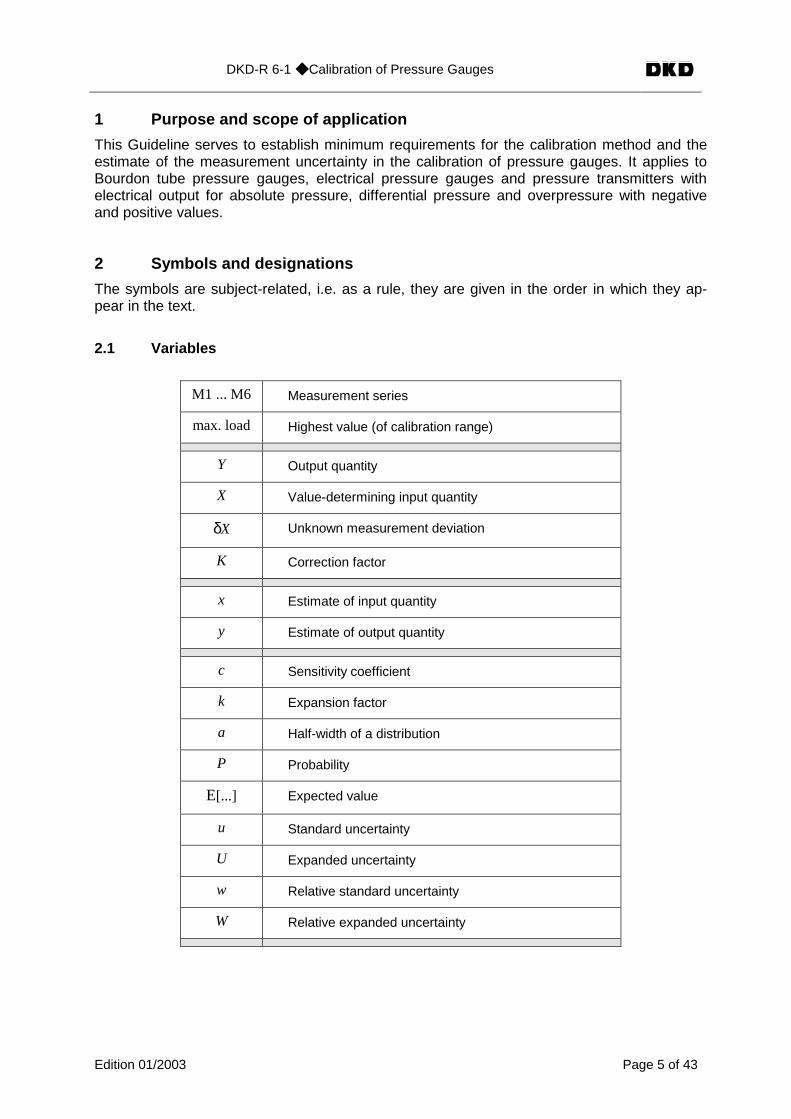
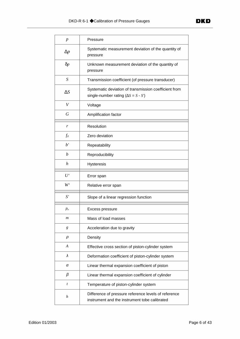
2 Symbols and designations
The symbols are subject-related, i.e. as a rule, they are given in the order in which they ap-pear in the text.
2.1 Variables
M1 ... M6 Measurement series
max. load Highest value (of calibration range)
Y Output quantity
X Value-determining input quantity
δX Unknown measurement deviation
K Correction factor
x Estimate of input quantity
y Estimate of output quantity
c Sensitivity coefficient
k Expansion factor
a Half-width of a distribution
P Probability
E[...] Expected value
u Standard uncertainty
U Expanded uncertainty
w Relative standard uncertainty
W Relative expanded uncertainty
DKD-R 6-1 ◆ Calibration of Pressure Gauges
Edition 01/2003 Page 6 of 43
p Pressure
∆pSystematic measurement deviation of the quantity of
pressure
δp Unknown measurement deviation of the quantity of
pressure
S Transmission coefficient (of pressure transducer)
∆SSystematic deviation of transmission coefficient from
single-number rating (∆S = S - S‘)
V Voltage
G Amplification factor
r Resolution
f0 Zero deviation
b' Repeatability
b Reproducibility
h Hysteresis
U‘ Error span
W‘ Relative error span
S' Slope of a linear regression function
pe Excess pressure
m Mass of load masses
g Acceleration due to gravity
ρ Density
A Effective cross section of piston-cylinder system
λ Deformation coefficient of piston-cylinder system
α Linear thermal expansion coefficient of piston
β Linear thermal expansion coefficient of cylinder
t Temperature of piston-cylinder system
hDifference of pressure reference levels of reference
instrument and the instrument tobe calibrated
DKD-R 6-1 ◆ Calibration of Pressure Gauges
Edition 01/2003 Page 7 of 43
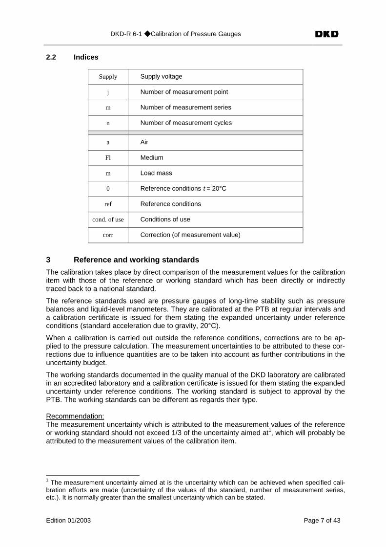
2.2 Indices
Supply Supply voltage
j Number of measurement point
m Number of measurement series
n Number of measurement cycles
a Air
Fl Medium
m Load mass
0 Reference conditions t = 20°C
ref Reference conditions
cond. of use Conditions of use
corr Correction (of measurement value)
3 Reference and working standards
The calibration takes place by direct comparison of the measurement values for the calibrationitem with those of the reference or working standard which has been directly or indirectlytraced back to a national standard.
The reference standards used are pressure gauges of long-time stability such as pressurebalances and liquid-level manometers. They are calibrated at the PTB at regular intervals anda calibration certificate is issued for them stating the expanded uncertainty under referenceconditions (standard acceleration due to gravity, 20°C).
When a calibration is carried out outside the reference conditions, corrections are to be ap-plied to the pressure calculation. The measurement uncertainties to be attributed to these cor-rections due to influence quantities are to be taken into account as further contributions in theuncertainty budget.
The working standards documented in the quality manual of the DKD laboratory are calibratedin an accredited laboratory and a calibration certificate is issued for them stating the expandeduncertainty under reference conditions. The working standard is subject to approval by thePTB. The working standards can be different as regards their type.
Recommendation:The measurement uncertainty which is attributed to the measurement values of the referenceor working standard should not exceed 1/3 of the uncertainty aimed at1, which will probably beattributed to the measurement values of the calibration item.
1 The measurement uncertainty aimed at is the uncertainty which can be achieved when specified cali-bration efforts are made (uncertainty of the values of the standard, number of measurement series,etc.). It is normally greater than the smallest uncertainty which can be stated.
DKD-R 6-1 ◆ Calibration of Pressure Gauges
Edition 01/2003 Page 8 of 43
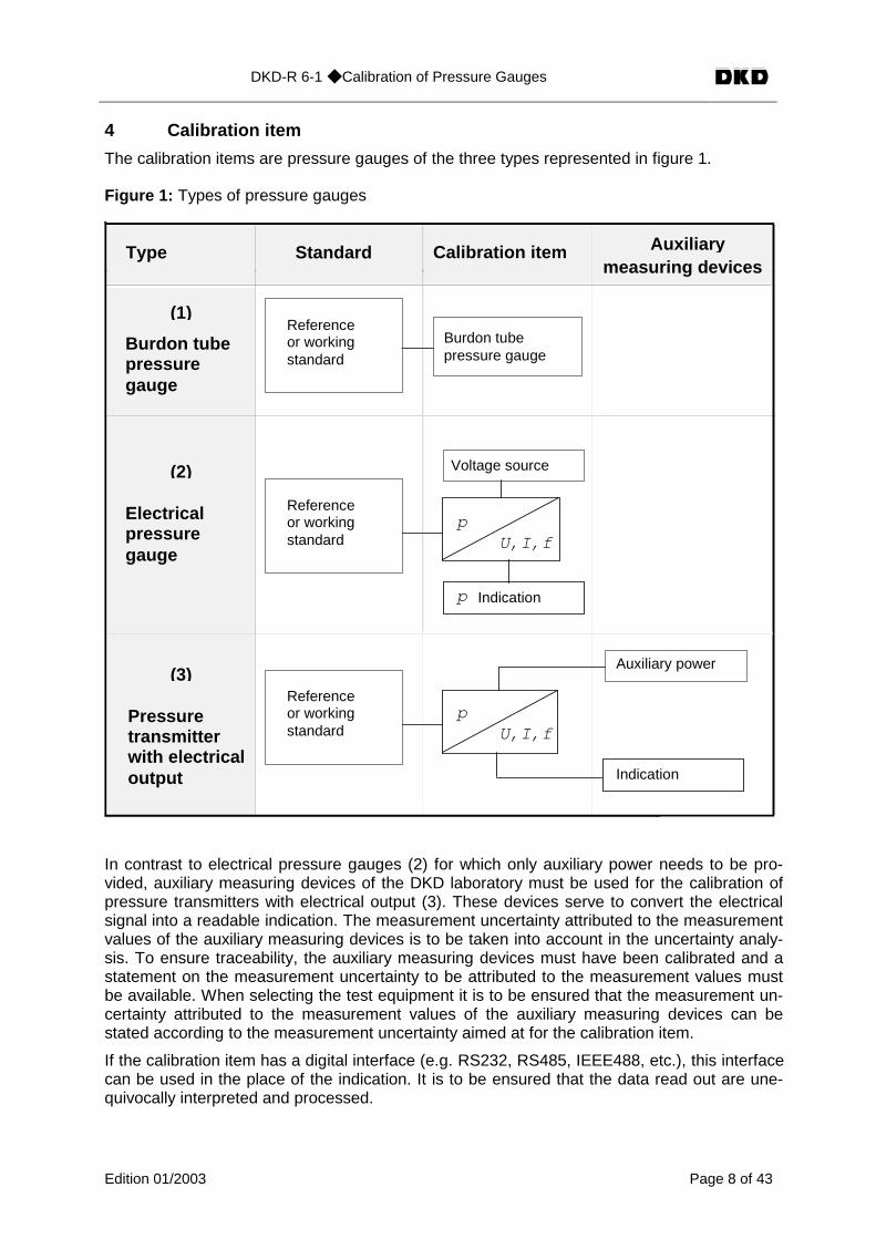
4 Calibration item
The calibration items are pressure gauges of the three types represented in figure 1.
Figure 1: Types of pressure gauges
Standard Calibration item Auxiliar ymeasuring devices
(1)
Type
Burdon tubepressuregauge
(2)
Electricalpressuregauge
(3)
Burdon tubepressure gauge
p
Voltage source
Indication
Auxiliary power
p
Referenceor workingstandard
Referenceor workingstandard
Referenceor workingstandard
U,I,f
p
Indication
Pressuretransmitterwith electricaloutput
U,I,f
In contrast to electrical pressure gauges (2) for which only auxiliary power needs to be pro-vided, auxiliary measuring devices of the DKD laboratory must be used for the calibration ofpressure transmitters with electrical output (3). These devices serve to convert the electricalsignal into a readable indication. The measurement uncertainty attributed to the measurementvalues of the auxiliary measuring devices is to be taken into account in the uncertainty analy-sis. To ensure traceability, the auxiliary measuring devices must have been calibrated and astatement on the measurement uncertainty to be attributed to the measurement values mustbe available. When selecting the test equipment it is to be ensured that the measurement un-certainty attributed to the measurement values of the auxiliary measuring devices can bestated according to the measurement uncertainty aimed at for the calibration item.
If the calibration item has a digital interface (e.g. RS232, RS485, IEEE488, etc.), this interfacecan be used in the place of the indication. It is to be ensured that the data read out are une-quivocally interpreted and processed.

DKD-R 6-1 ◆ Calibration of Pressure Gauges
Edition 01/2003 Page 9 of 43
5 Calibratability
Handling of a calibration task presupposes calibratability (suitability of the calibration item), i.e.the state of the calibration item at the time of calibration should comply with the generally ac-cepted rules of technology and with the particular specifications of the manufacturer's docu-mentation. The calibratability is to be ascertained by external inspections and function tests.
External inspections cover for example:
- visual inspection for damage (pointer, threads, sealing surface, pressure channel)
- contamination and cleanness
- visual inspections of inscriptions, readability of indications
- test whether the documents necessary for calibration (technical data, operating instruc-tions) have been submitted.
Function tests cover for example:
- tightness of tube system of calibration item
- electrical function
- perfect function of actuators (e.g. zero adjustability)
- setting elements in defined position
- faultless execution of self-checking and/or self-setting functions; if needed, internal ref-erence values are to be read out via the EDP interface
- torque dependence (zero signal) during mounting
Note:If repair or adjustment work has to be carried out to ensure calibratability, this work has to beagreed upon between customer and calibration laboratory.
6 Ambient conditions
The calibration is to be carried out after temperature equalization between calibration item andenvironment. A period for warming up the calibration item or potential warming-up of the cali-bration item due to the supply voltage is to be taken into account.
The calibration is to be performed at an ambient temperature stable to within ±1 K; this tem-perature must lie between 18°C and 28°C and is to be recorded.
Note:If the air density has an effect on the calibration result, not only the ambient temperature butalso the atmospheric pressure and the relative humidity are to be recorded.

DKD-R 6-1 ◆ Calibration of Pressure Gauges
Edition 01/2003 Page 10 of 43
7 Calibration methods
- The pressure gauge is to be calibrated as a whole (measuring chain), if possible.
- The specified mounting position is to be taken into consideration
- The calibration is to be carried out in measurement points uniformly distributed over thecalibration range.
- Depending on the measurement uncertainty aimed at, one or several measurement se-ries are necessary.
- If the behaviour of the calibration item as regards the influence of the torque duringmounting is not sufficiently known, the calibration item has to be clamped once again todetermine the reproducibility. In this case, the torque is to be measured and docu-mented.
Upon application, further influence quantities (e.g. temperature effects from other measure-ment series at different temperatures) can be determined.
The comparison between the measurement values for calibration item and reference or work-ing standard can be performed by two different methods:
- adjustment of the pressure according to the indication of the calibration item,
- adjustment of the pressure according to the indication of the standard.
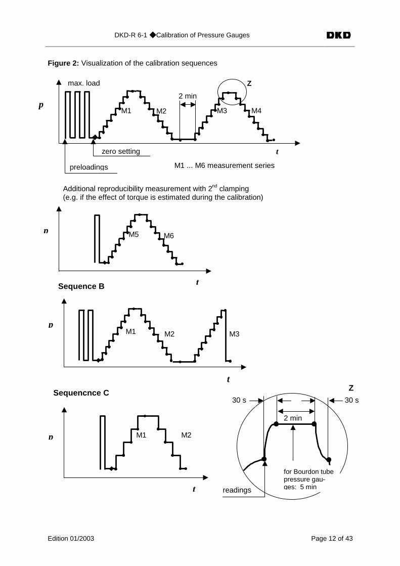
The time for preloading at the highest value and the time between two preloadings should beat least 30 seconds. After preloading and after steady-state conditions have been reached –and the calibration item permitting -, the indication of the calibration item is set to zero. Thezero reading is carried out immediately afterwards. For the pressure step variation in a meas-urement series, the time between two successive load steps should be the same and not beshorter than 30 seconds and the reading should be made 30 seconds after the start of thepressure change at the earliest. Especially Bourdon tube pressure gauges have to be slightlytapped to minimize any frictional effect of the pointer system. The measurement value for theupper limit of the calibration range is to be recorded prior to and after the waiting time. Thezero reading at the end of a measurement series is made 30 seconds after complete relief atthe earliest.
The calibration effort is shown in table 1 and figure 2 in dependence on the measurement un-certainty aimed at (see 1 on page 7). Figure 2 shows the sequence of the calibration.
DKD-R 6-1 ◆ Calibration of Pressure Gauges
Edition 01/2003 Page 11 of 43
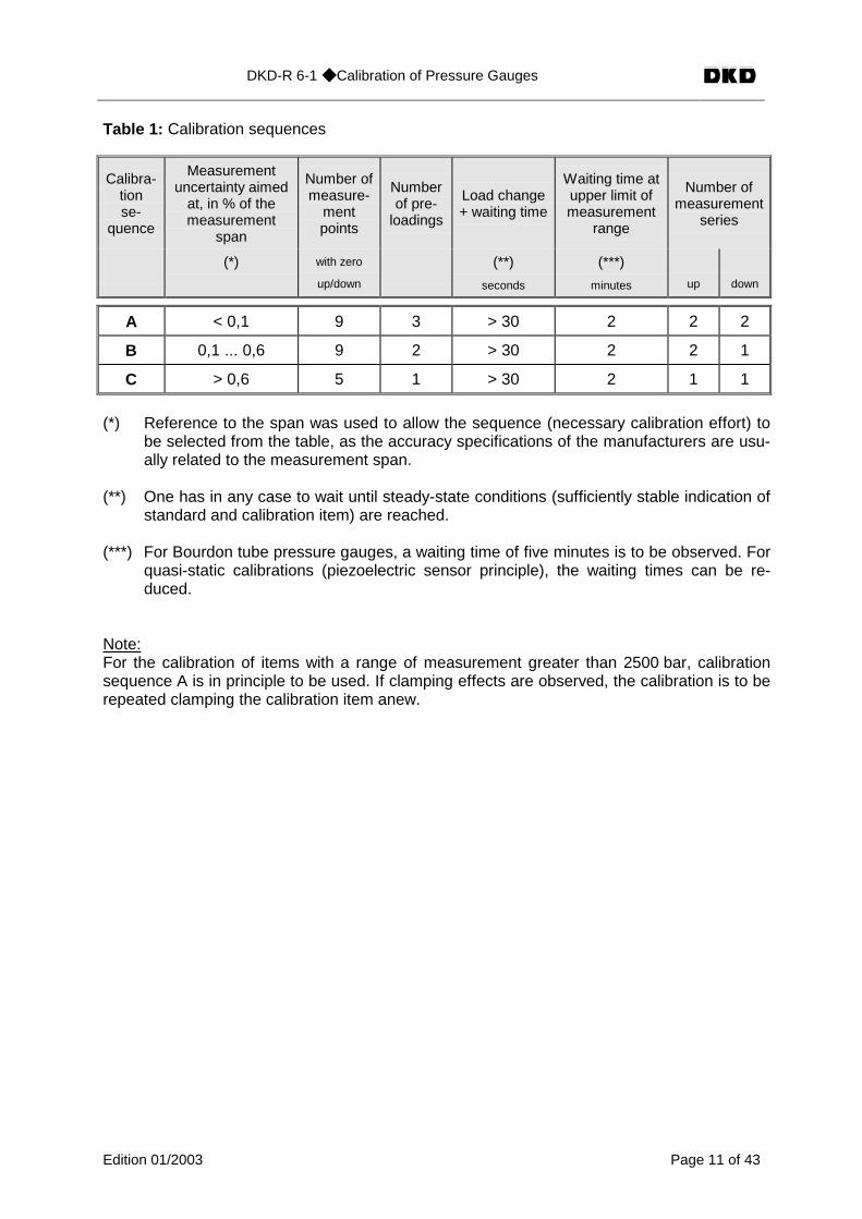
Table 1: Calibration sequences
Calibra-tionse-
quence
Measurementuncertainty aimed
at, in % of themeasurement
span
Number ofmeasure-
mentpoints
Numberof pre-
loadings
Load change+ waiting time
Waiting time atupper limit ofmeasurement
range
Number ofmeasurement
series
(*) with zero
up/down
(**)
seconds
(***)
minutes up down
A < 0,1 9 3 > 30 2 2 2
B 0,1 ... 0,6 9 2 > 30 2 2 1
C > 0,6 5 1 > 30 2 1 1
(*) Reference to the span was used to allow the sequence (necessary calibration effort) tobe selected from the table, as the accuracy specifications of the manufacturers are usu-ally related to the measurement span.
(**) One has in any case to wait until steady-state conditions (sufficiently stable indication ofstandard and calibration item) are reached.
(***) For Bourdon tube pressure gauges, a waiting time of five minutes is to be observed. Forquasi-static calibrations (piezoelectric sensor principle), the waiting times can be re-duced.
Note:For the calibration of items with a range of measurement greater than 2500 bar, calibrationsequence A is in principle to be used. If clamping effects are observed, the calibration is to berepeated clamping the calibration item anew.
DKD-R 6-1 ◆ Calibration of Pressure Gauges
Edition 01/2003 Page 12 of 43
Figure 2: Visualization of the calibration sequences
Additional reproducibility measurement with 2nd clamping(e.g. if the effect of torque is estimated during the calibration)
p
t
M6M5
Sequencnce C
M1p
t
M2
2 min
readings
30 s 30 s1
for Bourdon tubepressure gau-ges: 5 min
M3M2M1p
t
Sequence B
preloadings
Z
M1 ... M6 measurement series
Z
p
zero setting
M3 M4M2M1
max. load
t
2 min
DKD-R 6-1 ◆ Calibration of Pressure Gauges
Edition 01/2003 Page 13 of 43
8 Measurement uncertainty 2
8.1 Definition
Parameter which is stated jointly with the measurement result, i.e. which is attributed by themeasurement to the measurement result and characterizes the interval of values which canbe reasonably assigned to the measurand on the basis of the measurement.
8.2 Procedure
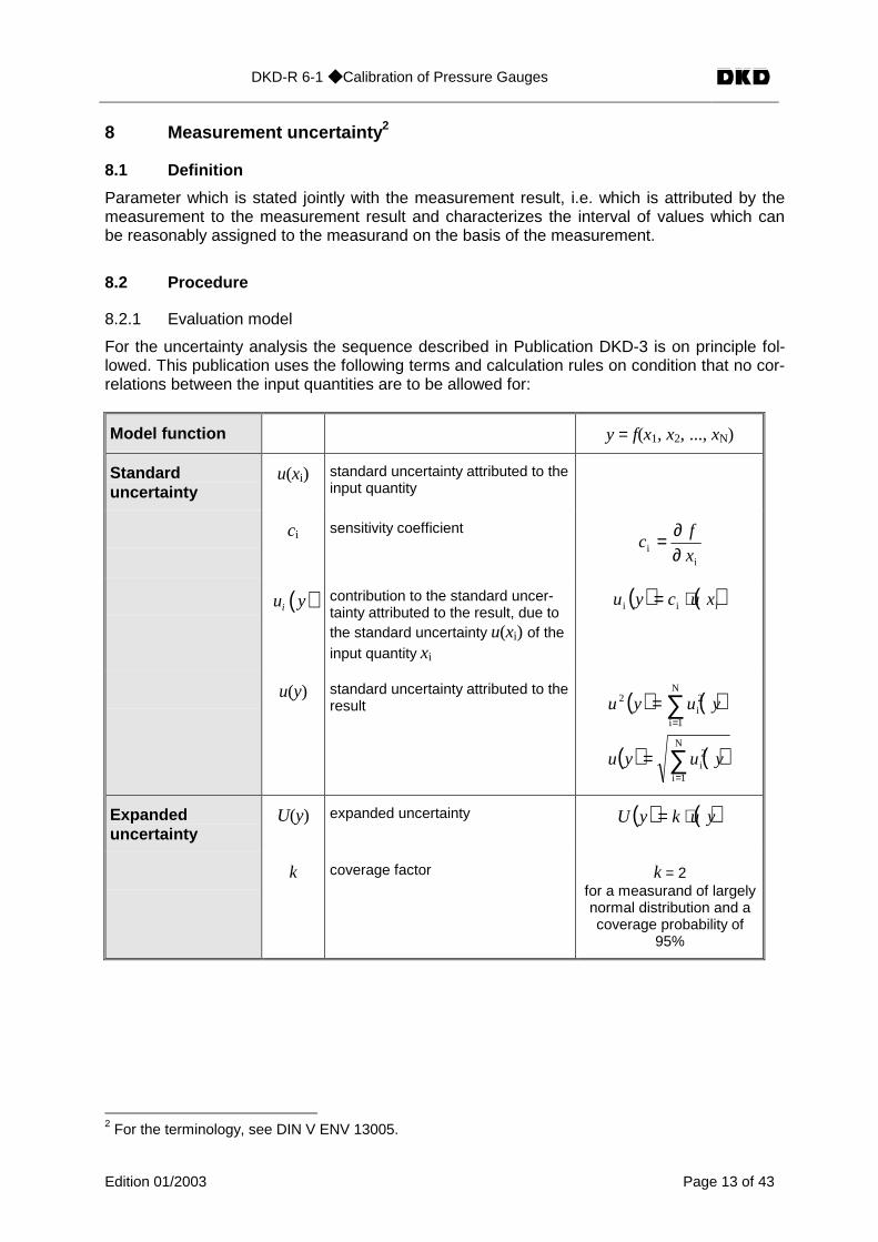
8.2.1 Evaluation model
For the uncertainty analysis the sequence described in Publication DKD-3 is on principle fol-lowed. This publication uses the following terms and calculation rules on condition that no cor-relations between the input quantities are to be allowed for:
Model function y = f(x1, x2, ..., xN)
Standarduncertainty
u(xi) standard uncertainty attributed to theinput quantity
ci sensitivity coefficient
ii
x
fc
∂∂=
( )iu y contribution to the standard uncer-tainty attributed to the result, due tothe standard uncertainty u(xi) of theinput quantity xi
( ) ( )iii xucyu ⋅=
u(y) standard uncertainty attributed to theresult ( ) ( )
( ) ( )∑
∑
=
=
=
=
N
1i
2i
N
1i
2i
2
yuyu
yuyu
Expandeduncertainty
U(y) expanded uncertainty ( ) ( )yukyU ⋅=
k coverage factor k = 2for a measurand of largelynormal distribution and acoverage probability of
95%
2 For the terminology, see DIN V ENV 13005.
DKD-R 6-1 ◆ Calibration of Pressure Gauges
Edition 01/2003 Page 14 of 43
If relative measurement uncertainties are used, the variables u, U are replaced with the vari-ables w, W.
With complex models, the calculation rule rapidly leads to an analytical determination of thesensitivity coefficient which is no longer manageable. As a result, the sensitivity coefficientswill have to be determined numerically with the aid of a computer.
Besides this general calculation rule, two particular rules are available which lead to sensitivitycoefficients ci = ± 1 and thus to the simple quadratic addition of the uncertainties of the inputquantities. This simplifies the uncertainty analysis and makes EDP program support unneces-sary.
Note:The "simple" model, too, must of course correctly reflect the physical measurement/calibrationprocess. If appropriate, complex relations must be represented in a suitable model (no specialcase) in a separate uncertainty budget (see Annex A: Estimate of measurement uncertainty tobe attributed to the values of the pressure balance under conditions of use)
8.2.2 Sum/difference model
∑=
+=N
1ii/XXY (1)
Y measurand or output quantityX input quantity/quantities according to the functional relationship Y = f(X1, X2, ... Xn)
δX i unknown measurement deviation(s)
E [δX i ] = 0 expected value[the components do not contribute to the determination of the outputquantity (corrections are not applied) but they make a contributionto the measurement uncertainty]
e.g. model for determining the measurement deviation of the indication:
∑=
+−=∆N
1iistandardind /pppp (2)
This model is most suitable for calibration items with an indication of their own in pressureunits (e.g. Bourdon tube pressure gauge, electrical pressure gauge). Here the measurementuncertainties are also stated in the unit of the physical quantity of pressure (pascal, bar, etc.).
8.2.3 Product/quotient model
∏=
⋅=N
1iiKXY (3)
Y output quantityX value-determining input quantity/quantities
Ki = (1 + δXi ) correction factor(s)
δX i unknown deviation(s)
DKD-R 6-1 ◆ Calibration of Pressure Gauges
Edition 01/2003 Page 15 of 43
E [δXi ] = 0; E [Ki] = 1 expected values[the components do not contribute to the determination of the outputquantity (corrections are not applied) but they make a contributionto the measurement uncertainty]
e.g. model for determining the transmission coefficient of a pressure transducer(strain-gauge transducer):
( ) ∏=
⋅ ⋅==N
1ii
standardin
out supply
ind
KpX
XS
VGV
(4)
This model is most suitable for calibration items without an indication of their own (e.g. pres-sure transmitter with electrical output) using related measurement uncertainties (dimension-less).
8.2.4 Input quantities
The measurement uncertainties attributed to the input quantities are subdivided into two cate-gories as regards their determination:
Type A: For the determination of the value and the standard uncertainty attributed to it,analysis methods from statistics for measurement series under repeatability con-ditions ( n ≥ 10 ) are applied.
Type B: The determination of the value and of the standard uncertainty attributed to it isbased on other scientific findings and can be estimated from the following infor-mation:
− data from previous measurements,− general knowledge and experience regarding the characteristics and the
behaviour of measuring instruments and materials,− manufacturer's specifications,− calibration and other certificates,− reference data from manuals.
In many cases, only the upper and lower bounds a+ and a- can be stated for thevalue of a quantity, whereby all values within the bounds can be consideredequally probable. This situation can best be described by a rectangular probabilitydensity.
With a+ - a- = 2 a (5)
the estimate of the input quantity
( )−+ +⋅= aax2
1i (6)
and the attributed standard uncertainty
( )3
i
au x = (7)
are obtained.
DKD-R 6-1 ◆ Calibration of Pressure Gauges
Edition 01/2003 Page 16 of 43
If the values more likely lie in the centre or at the border of the interval, it is rea-sonable to assume a triangular or U-shaped distribution.
Table 2: Other type B distribution shapes
Distribution Standard uncertainty
triangular6
au =
U-shaped2
au =
etc.
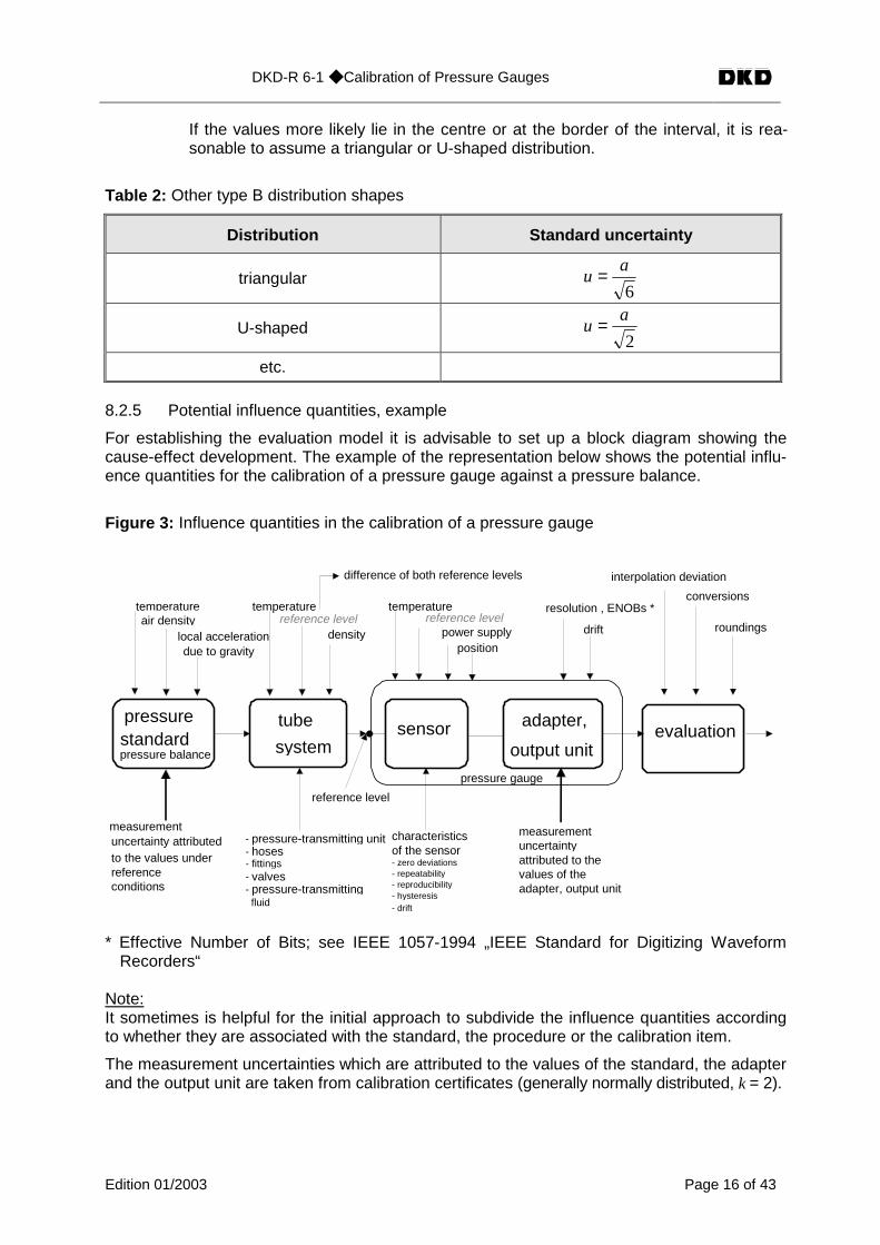
8.2.5 Potential influence quantities, example
For establishing the evaluation model it is advisable to set up a block diagram showing thecause-effect development. The example of the representation below shows the potential influ-ence quantities for the calibration of a pressure gauge against a pressure balance.
Figure 3: Influence quantities in the calibration of a pressure gauge
pressurestandardpressure balance
sensor adapter,
output unitevaluation
tube
system
temperatureair density
local accelerationdue to gravity
temperature
densityreference level
pressure gauge
measurementuncertainty attributedto the values underreferenceconditions
- pressure-transmitting unit- hoses- fittings- valves- pressure-transmitting fluid
reference level
characteristicsof the sensor- zero deviations- repeatability- reproducibility- hysteresis- drift
temperaturereference level
power supplyposition
resolution , ENOBs *
interpolation deviation
conversions
roundings
difference of both reference levels
drift
measurementuncertaintyattributed to thevalues of theadapter, output unit
* Effective Number of Bits; see IEEE 1057-1994 „IEEE Standard for Digitizing WaveformRecorders“
Note:It sometimes is helpful for the initial approach to subdivide the influence quantities accordingto whether they are associated with the standard, the procedure or the calibration item.
The measurement uncertainties which are attributed to the values of the standard, the adapterand the output unit are taken from calibration certificates (generally normally distributed, k = 2).
DKD-R 6-1 ◆ Calibration of Pressure Gauges
Edition 01/2003 Page 17 of 43
8.3 Calibration of Bourdon tube pressure gauges
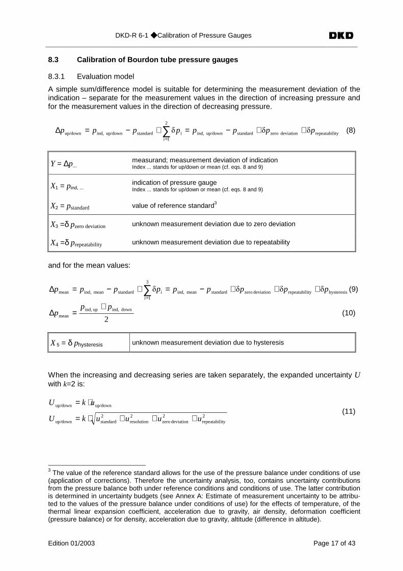
8.3.1 Evaluation model
A simple sum/difference model is suitable for determining the measurement deviation of theindication – separate for the measurement values in the direction of increasing pressure andfor the measurement values in the direction of decreasing pressure.
ityrepeatabildeviation zerostandardup/down ind,i
2
1istandardup/down ind,up/down /// pppppppp ++−=+−=∆ ∑
=
(8)
Y = ∆p...measurand; measurement deviation of indicationIndex ... stands for up/down or mean (cf. eqs. 8 and 9)
X1 = pind, ...indication of pressure gaugeIndex ... stands for up/down or mean (cf. eqs. 8 and 9)
X2 = pstandard value of reference standard3
X3 =δ pzero deviation unknown measurement deviation due to zero deviation
X4 =δ prepeatability unknown measurement deviation due to repeatability
and for the mean values:
hysteresisityrepeatabildeviation zerotandardmean ind,
3
1iistandardmean ind,mean //// ppppppppp s +++−=+−=∆ ∑
=
(9)
2down ind,up ind,
mean
ppp
+=∆ (10)
X 5 = δ physteresis unknown measurement deviation due to hysteresis
When the increasing and decreasing series are taken separately, the expanded uncertainty Uwith k=2 is:
2ityrepeatabil
2deviation zero
2resolution
2standardup/down
up/downup/down
uuuukU
ukU
+++⋅=
⋅=(11)
3 The value of the reference standard allows for the use of the pressure balance under conditions of use(application of corrections). Therefore the uncertainty analysis, too, contains uncertainty contributionsfrom the pressure balance both under reference conditions and conditions of use. The latter contributionis determined in uncertainty budgets (see Annex A: Estimate of measurement uncertainty to be attribu-ted to the values of the pressure balance under conditions of use) for the effects of temperature, of thethermal linear expansion coefficient, acceleration due to gravity, air density, deformation coefficient(pressure balance) or for density, acceleration due to gravity, altitude (difference in altitude).
DKD-R 6-1 ◆ Calibration of Pressure Gauges
Edition 01/2003 Page 18 of 43
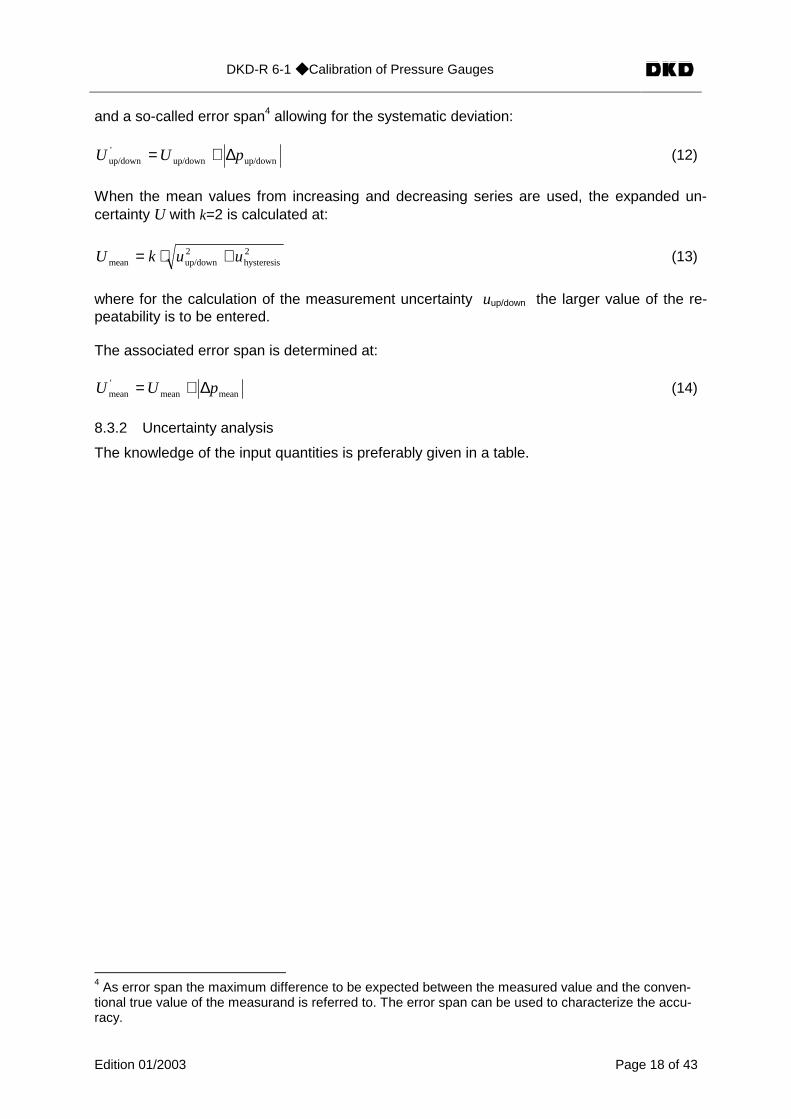
and a so-called error span4 allowing for the systematic deviation:
up/downup/down'up/down pUU ∆+= (12)
When the mean values from increasing and decreasing series are used, the expanded un-certainty U with k=2 is calculated at:
2hysteresis
2up/downmean uukU +⋅= (13)
where for the calculation of the measurement uncertainty uup/down the larger value of the re-peatability is to be entered.
The associated error span is determined at:
meanmean'mean pUU ∆+= (14)
8.3.2 Uncertainty analysis
The knowledge of the input quantities is preferably given in a table.
4 As error span the maximum difference to be expected between the measured value and the conven-tional true value of the measurand is referred to. The error span can be used to characterize the accu-racy.
DKD-R 6-1 ◆ Calibration of Pressure Gauges
Edition 01/2003 Page 19 of 43
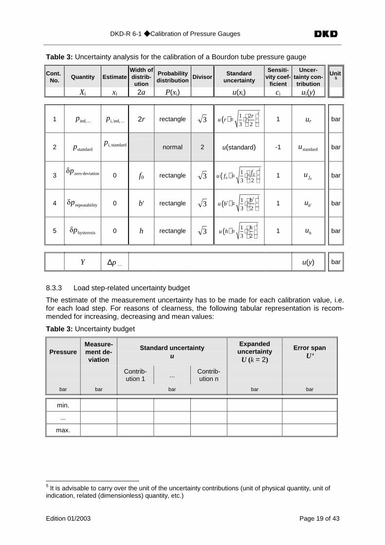
Table 3: Uncertainty analysis for the calibration of a Bourdon tube pressure gauge
Cont.No.
Quantity EstimateWidth ofdistrib-ution
Probabilitydistribution
DivisorStandard
uncertainty
Sensiti-vity coef-
ficient
Uncer-tainty con-tribution
Unit5
Xi xi 2a P(xi) u(xi) ci ui(y)
1 ... ind,p ... ind, i,p 2r rectangle 3 ( )2
1 2
3 2
ru r
= ⋅ 1 ur bar
2 standardp standard i,pnormal 2 u(standard) -1 standardu bar
3 deviation zero/p0 f0 rectangle 3 ( )
2
00
1
3 2
fu f
= ⋅ 1
0fu bar
4 ityrepeatabil/p 0 b‘ rectangle 3 ( )2
1
3 2
bu b
′ ′ = ⋅ 1 bu ′ bar
5 hysteresis/p 0 h rectangle 3 ( )2
1
3 2
hu h
= ⋅ 1 hu bar
Y ∆p ... u(y) bar
8.3.3 Load step-related uncertainty budget
The estimate of the measurement uncertainty has to be made for each calibration value, i.e.for each load step. For reasons of clearness, the following tabular representation is recom-mended for increasing, decreasing and mean values:
Table 3: Uncertainty budget
PressureMeasure-ment de-viation
Standard uncertaintyu
ExpandeduncertaintyU (k = 2)
Error spanU‘
Contrib-ution 1
... Contrib-ution n
bar bar bar bar bar
min.
...
max.
5 It is advisable to carry over the unit of the uncertainty contributions (unit of physical quantity, unit ofindication, related (dimensionless) quantity, etc.)
DKD-R 6-1 ◆ Calibration of Pressure Gauges
Edition 01/2003 Page 20 of 43
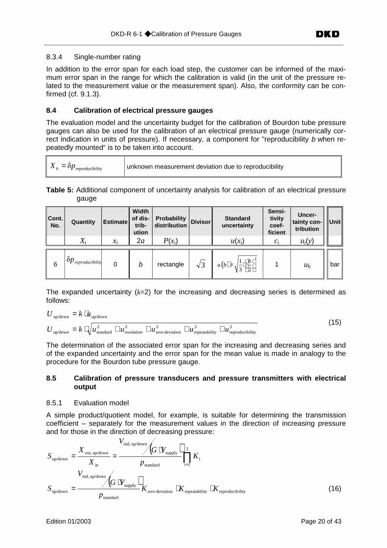
8.3.4 Single-number rating
In addition to the error span for each load step, the customer can be informed of the maxi-mum error span in the range for which the calibration is valid (in the unit of the pressure re-lated to the measurement value or the measurement span). Also, the conformity can be con-firmed (cf. 9.1.3).
8.4 Calibration of electrical pressure gauges
The evaluation model and the uncertainty budget for the calibration of Bourdon tube pressuregauges can also be used for the calibration of an electrical pressure gauge (numerically cor-rect indication in units of pressure). If necessary, a component for "reproducibility b when re-peatedly mounted“ is to be taken into account.
ilityreproducib6 /pX = unknown measurement deviation due to reproducibility
Table 5: Additional component of uncertainty analysis for calibration of an electrical pressuregauge
Cont.No.
Quantity Estimate
Widthof dis-trib-ution
Probabilitydistribution
DivisorStandard
uncertainty
Sensi-tivitycoef-
ficient
Uncer-tainty con-tribution
Unit
Xi xi 2a P(xi) u(xi) ci ui(y)
6 ilit yreproducibp/0 b rectangle 3 ( )
21
3 2
bu b
= ⋅ 1 ub bar
The expanded uncertainty (k=2) for the increasing and decreasing series is determined asfollows:
2ilityreproducib
2ityrepeatabil
2deviation zero
2resolution
2standardup/down
up/downup/down
uuuuukU
ukU
++++⋅=
⋅=(15)
The determination of the associated error span for the increasing and decreasing series andof the expanded uncertainty and the error span for the mean value is made in analogy to theprocedure for the Bourdon tube pressure gauge.
8.5 Calibration of pressure transducers and pressure transmitters with electricaloutput
8.5.1 Evaluation model
A simple product/quotient model, for example, is suitable for determining the transmissioncoefficient – separately for the measurement values in the direction of increasing pressureand for those in the direction of decreasing pressure:
( )∏
=
⋅==
3
1ii
standard
supply
up/down ind,
in
up/down out,up/down K
p
VGV
X
XS
( )ilityreproducibityrepeatabildeviation zero
standard
supply
up/down ind,
up/down KKKp
VGV
S ⋅⋅⋅
= (16)
DKD-R 6-1 ◆ Calibration of Pressure Gauges
Edition 01/2003 Page 21 of 43
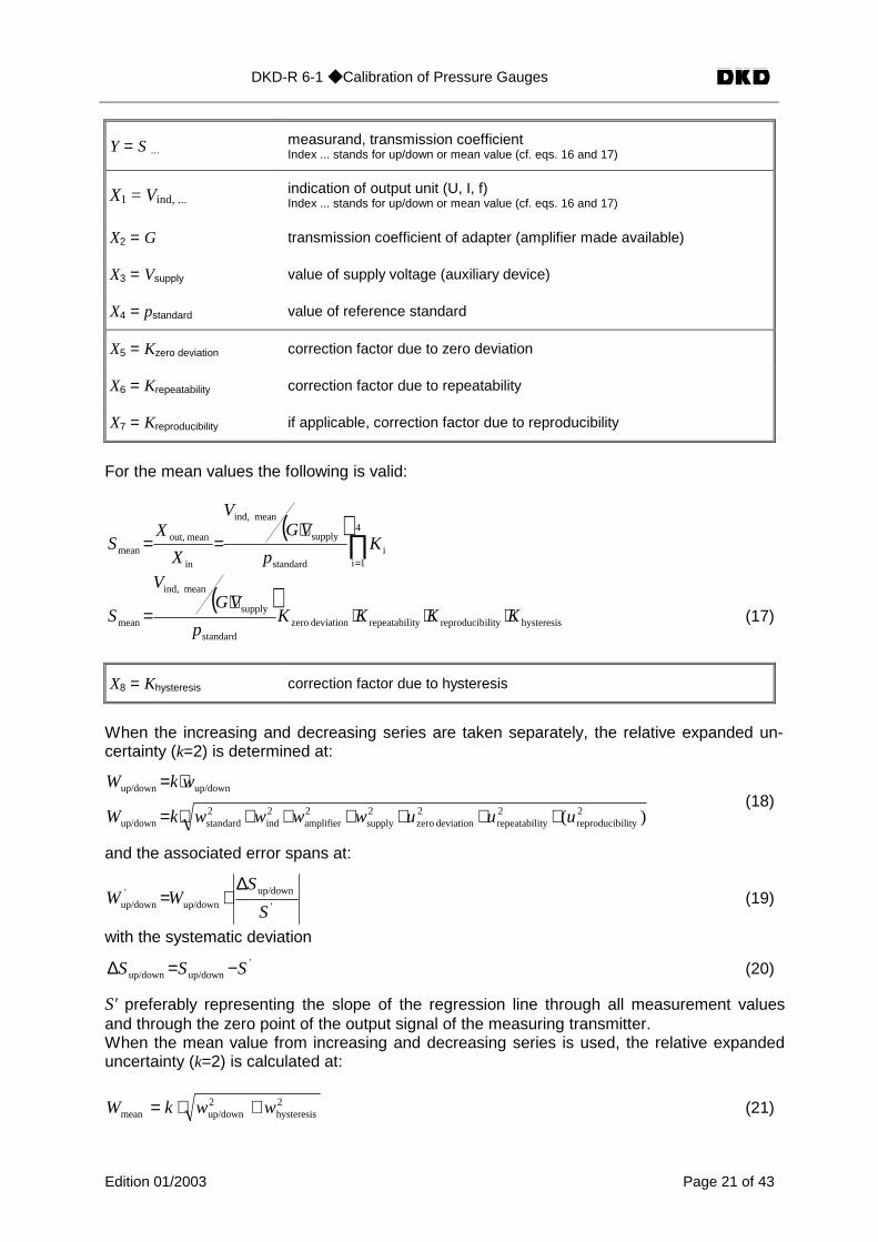
Y = S ... measurand, transmission coefficientIndex ... stands for up/down or mean value (cf. eqs. 16 and 17)
X1 = Vind, ...indication of output unit (U, I, f)Index ... stands for up/down or mean value (cf. eqs. 16 and 17)
X2 = G transmission coefficient of adapter (amplifier made available)
X3 = Vsupply value of supply voltage (auxiliary device)
X4 = pstandard value of reference standard
X5 = Kzero deviation correction factor due to zero deviation
X6 = Krepeatability correction factor due to repeatability
X7 = Kreproducibility if applicable, correction factor due to reproducibility
For the mean values the following is valid:
( )∏
=
⋅==
4
1ii
standard
supply
mean ind,
in
mean out,mean K
p
VGV
X
XS
( )hysteresisilityreproducibityrepeatabildeviation zero
standard
supply
mean ind,
mean KKKKp
VGV
S ⋅⋅⋅⋅
= (17)
X8 = Khysteresis correction factor due to hysteresis
When the increasing and decreasing series are taken separately, the relative expanded un-certainty (k=2) is determined at:
)( 2ilityreproducib
2ityrepeatabil
2deviation zero
2supply
2amplifier
2ind
2standardup/down
up/downup/down
uuuwwwwkW
wkW
++++++⋅=
⋅=(18)
and the associated error spans at:
'
up/downup/down
'up/down
S
SWW
∆+= (19)
with the systematic deviation'
up/downup/down SSS −=∆ (20)
S' preferably representing the slope of the regression line through all measurement valuesand through the zero point of the output signal of the measuring transmitter.When the mean value from increasing and decreasing series is used, the relative expandeduncertainty (k=2) is calculated at:
2hysteresis
2up/downmean wwkW +⋅= (21)
DKD-R 6-1 ◆ Calibration of Pressure Gauges
Edition 01/2003 Page 22 of 43
where for the calculation of the measurement uncertainty wup/down the larger value of the re-peatability is to be inserted.
The associated error span is determined at:
'mean
mean'
mean S
SWW
∆+= (22)
with
'meanmean SSS −=∆ (23)
For S', cf. above.
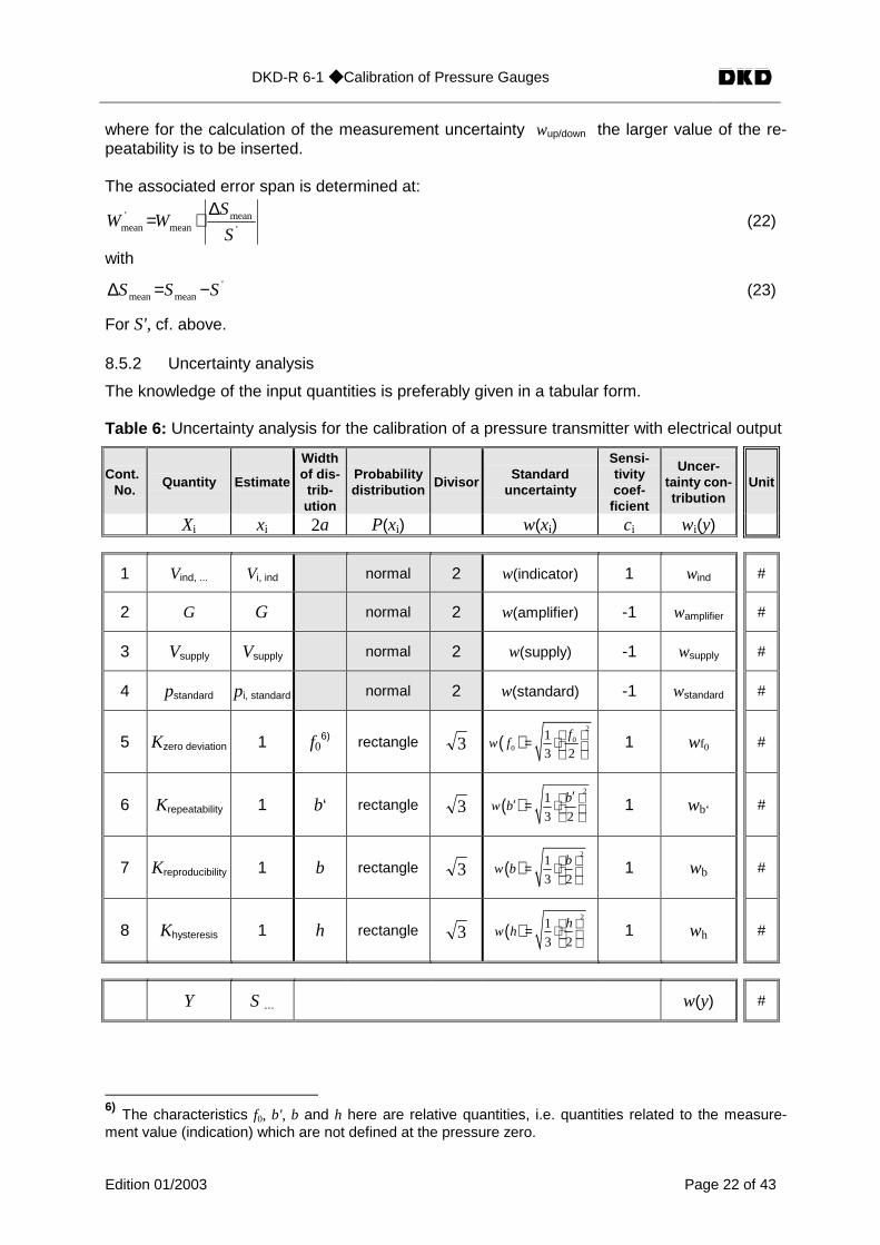
8.5.2 Uncertainty analysis
The knowledge of the input quantities is preferably given in a tabular form.
Table 6: Uncertainty analysis for the calibration of a pressure transmitter with electrical output
Cont.No.
Quantity Estimate
Widthof dis-trib-ution
Probabilitydistribution
DivisorStandard
uncertainty
Sensi-tivitycoef-
ficient
Uncer-tainty con-tribution
Unit
Xi xi 2a P(xi) w(xi) ci wi(y)
1 Vind, ... Vi, ind normal 2 w(indicator) 1 wind #
2 G G normal 2 w(amplifier) -1 wamplifier #
3 Vsupply Vsupply normal 2 w(supply) -1 wsupply #
4 pstandard pi, standard normal 2 w(standard) -1 wstandard #
5 Kzero deviation 1 f06) rectangle 3 ( )
2
00
1
3 2
fw f
= ⋅ 1 wf0 #
6 Krepeatability 1 b‘ rectangle 3 ( )2
1
3 2
bw b
′ ′ = ⋅ 1 wb‘ #
7 Kreproducibility 1 b rectangle 3 ( )2
1
3 2
bw b
= ⋅ 1 wb #
8 Khysteresis 1 h rectangle 3 ( )2
1
3 2
hw h
= ⋅ 1 wh #
Y S ... w(y) #
6) The characteristics f0, b', b and h here are relative quantities, i.e. quantities related to the measure-ment value (indication) which are not defined at the pressure zero.

DKD-R 6-1 ◆ Calibration of Pressure Gauges
Edition 01/2003 Page 23 of 43
8.5.3 Load step-related uncertainty budget
The estimate of the measurement uncertainty has to be made for each calibration value, i.e.for each load step. For reasons of clearness, the following tabular representation is recom-mended for increasing, decreasing and mean values:
Table 7: Uncertainty budget
Pressure Rel. standard uncertaintyw
Rel. expandeduncertainty W
(k=2)
Contribution1
... Contributionn
bar # #
min.
...
max.
8.5.4 Single-number rating
Transmission coefficient as slope of a linear regression function
For the use of the pressure transducer it is common practice not to apply different transmis-sion coefficients for the individual load steps (= calibration pressures) but one single transmis-sion coefficient for the whole range for which the calibration is valid. This preferably is theslope of the regression line through all measurement values and through the zero point of theoutput signal of the measuring transmitter (fitting without absolute term).
When this characteristic of the pressure transducer is used, a statement of conformity is sub-stituted for the measurement uncertainties attributed to the individual values measured for thetransmission coefficient (cf. 9.1.3).
For this purpose, the upper limiting amounts of the deviation are to be defined. This can bemade on the basis of the calibration results by calculation of the error spans according to8.5.1 ("self-determined conformity," definition on the basis of manufacturer's statements, cf.below). In this operation,
- the measurement uncertainties attributed to the individual measurement values of thetransmission coefficient and
- the deviations of these values from the single-number rating of the transmission coeffi-cient
are to be taken into account.
As a rule, error spans result whose magnitudes decrease with increasing pressure. As theupper limiting amounts of the deviation
- the maximum calculated error span can be selected (in this case, the upper limitingamounts of the deviation are represented in the calibration diagram as straight linesparallel to the pressure axis, cf. 9.2, pressure transmitters with electrical output signal,figure 5, upper details) or
- the upper limiting amounts of the deviation are described by suitable curves such ashyperbolas or polynomials (cf. 9.2, pressure transmitters with electrical output signal,figure 5, lower details).
DKD-R 6-1 ◆ Calibration of Pressure Gauges
Edition 01/2003 Page 24 of 43
Note:The use of pressure-dependent upper limiting amounts of the deviation is not common prac-tice. In pressure measurements with the calibrated device in the upper part of the measure-ment range, it allows, however, smaller measurement uncertainties to be stated.
For calibration items whose nominal parameter (e.g. 2 mV/V) has been balanced by themanufacturer, the upper limiting amounts of the deviation can alternatively be determinedfrom the associated parameter tolerance. In this case, it is, however, always to be checkedwhether the values of the transmission coefficients determined in the calibration, includingtheir attributed measurement uncertainties and systematic deviations from the single-numberrating of the parameter do not exceed the upper limiting amounts of the deviation.
8.6 Determination of relevant parameters for uncertainty analysis
8.6.1 Resolution r
8.6.1.1 Analog indicating devices
The resolution of the indicating device is obtained from the ratio of the pointer width to thecentre distance of two neighbouring graduation lines (scale interval). 1/2, 1/5 or 1/10 is rec-ommended as ratio. If 1/10 is chosen as the ratio (i.e. the estimable fraction of a scale inter-val), the scale spacing must be 2,5 mm or greater (cf. also DIN 43790).
Note:The best estimate for an analog indicating device is determined by visual interpolation. Thesmallest estimable fraction of a scale interval is the interpolation component (r) by which themeasurement values can be distinguished. The variation interval for the best estimate (x) thusis a+ = x + r and a- = x - r with the width of the rectangular distribution being 2a = 2r.
8.6.1.2 Digital indicating devices
If the indication varies by one digital step at most when the pressure gauge is not loaded, theresolution corresponds to the digital step.
Note:For the determination of the uncertainty contribution, half the value of the resolution (a = r/2)is assigned to the half-width of the rectangular distribution. This uncertainty contribution doesnot explicitly appear in section 8.5 as it is contained in the measurement uncertainty of theoutput unit (display) (statement in calibration certificate).
8.6.1.3 Fluctuation of readings
If the readings fluctuate by more than the value previously determined for the resolution withthe pressure gauge not being loaded, the resolution r is to be taken as half the span of thefluctuation, additionally added with a digital step.
8.6.2 Zero deviation f0
The zero point can be set prior to every measurement cycle consisting of an increasing and adecreasing series and must be recorded prior to and after every measurement cycle. Thereading is to be made with the instrument being completely relieved.
DKD-R 6-1 ◆ Calibration of Pressure Gauges
Edition 01/2003 Page 25 of 43
The zero deviation is calculated as follows:
{ }0 2 0 1 0 4 0 3 0 6 0 5 0= m ax , ,, , , , , ,f x x x x x x− − − (24)
The indices number the measurement values x read in the zero points of the measurementseries M1 to M6.
8.6.3 Repeatability b'
The repeatability with the mounting not being changed is determined from the difference ofthe zero signal-corrected measurement values of corresponding measurement series.
( ) ( )( ) ( )
{ }'j down,
'j up,
'j mean,
0 2,j 2,0 4,j 4,'
j down,
0 1,j 1,0 3,j 3,'
j up,
,max bbb
xxxxb
xxxxb
=
−−−=
−−−=
(25)
The index j numbers the nominal values of the pressure (j = 0: zero point).
8.6.4 Reproducibility b
The reproducibility with the instrument being mounted repeatedly and the conditions not beingchanged is determined from the difference of the zero signal-corrected measurement valuesof corresponding measurement series.
( ) ( )( ) ( )
{ }j down,j up,j mean,
0 2,j 2,0 6,j 6,j down,
0 1,j 1,0 5,j 5,j up,
,max bbb
xxxxb
xxxxb
=
−−−=
−−−=
(26)
For index j, see above.
8.6.5 Hysteresis h
When mean values are stated, the hysteresis is determined from the difference of the zeropoint-corrected measurement values of the increasing and decreasing series as follows:
( ) ( ) ( ) ( ) ( ) ( ){ }0 5,j 5,0 5,j 6,0 3,j 3,0 3,j 4,0 1,j 1,0 1,j 2,j mean, n
1xxxxxxxxxxxxh −−−+−−−+−−−⋅=
(27)
For index j, see above. The variable n stands for the number of the complete measurementcycles.
DKD-R 6-1 ◆ Calibration of Pressure Gauges
Edition 01/2003 Page 26 of 43
9. Evaluation of measurement results and statements in the calibrationcertificate
The main components of the pressure gauge are each provided with a calibration mark; de-vices belonging to a measuring chain are each provided with a calibration mark.
In addition to the requirements in DKD-5, the following information is to be stated in the cali-bration certificate:
- calibration method (DKD-R 6-1 sequence A, B, C or EN 837 parts 1 and 3)- pressure-transmitting medium- pressure reference plane on calibration item- position of calibration item for calibration- selected settings on calibration item
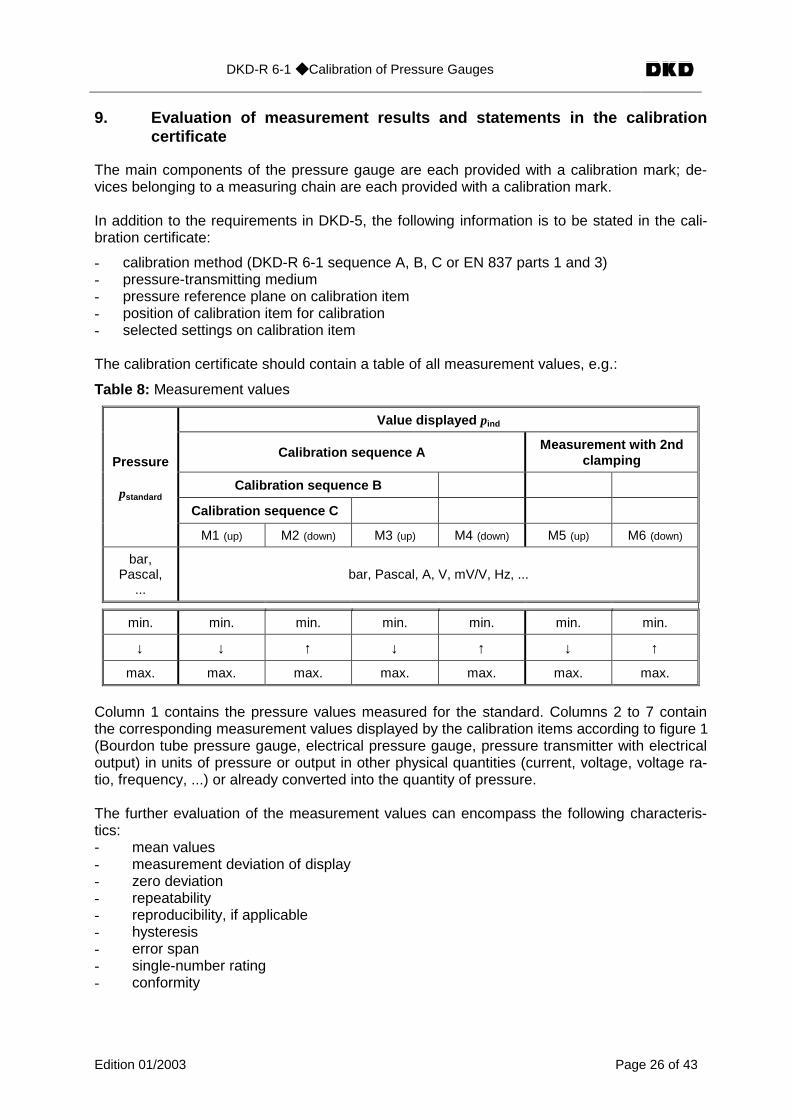
The calibration certificate should contain a table of all measurement values, e.g.:
Table 8: Measurement values
Value displayed pind
Calibration sequence A Measurement with 2ndclamping
Calibration sequence B
Calibration sequence C
Pressure
pstandard
M1 (up) M2 (down) M3 (up) M4 (down) M5 (up) M6 (down)
bar,Pascal,
...bar, Pascal, A, V, mV/V, Hz, ...
min. min. min. min. min. min. min.
↓ ↓ ↑ ↓ ↑ ↓ ↑
max. max. max. max. max. max. max.
Column 1 contains the pressure values measured for the standard. Columns 2 to 7 containthe corresponding measurement values displayed by the calibration items according to figure 1(Bourdon tube pressure gauge, electrical pressure gauge, pressure transmitter with electricaloutput) in units of pressure or output in other physical quantities (current, voltage, voltage ra-tio, frequency, ...) or already converted into the quantity of pressure.
The further evaluation of the measurement values can encompass the following characteris-tics:- mean values- measurement deviation of display- zero deviation- repeatability- reproducibility, if applicable- hysteresis- error span- single-number rating- conformity-

DKD-R 6-1 ◆ Calibration of Pressure Gauges
Edition 01/2003 Page 27 of 43
9.1 Determination of other parameters
9.1.1 Mean values x
The mean values x i,j with i = up/down, mean are calculated as follows:
( )
( )
2
6 4, 2,mfor 1
5 3, 1,mfor 1
j down,j up,mean
m0 1),-(mj m,j down,
m0 m,j m,j up,
xxx
xxl
x
xxl
x
+=
=−⋅=
=−⋅=
∑
∑
(28)
where variable l gives the number of measurement series.
9.1.2 Error span U‘
The error span is the sum of the expanded uncertainty (k=2) and the amount of the systematicdeviation. Due to the systematic component, the error span is assigned rectangular distribu-tion as distribution shape. The error span is to be determined according to the requirementsfor the mean values of the increasing and decreasing series and the mean value:
e.g.: U‘ = U + ∆p (29)
The relative error span W' is formed accordingly.
e.g.:'
'
S
SWW
∆+= (30)
Note:cf. also 4 on page 18.
9.1.3 Conformity
If the error span and the transmission coefficients with attributed measurement uncertainty liewithin the error limit stated by the manufacturer, the conformity according to DKD-5 can beconfirmed. The range for which it is valid is also to be stated.
DKD-R 6-1 ◆ Calibration of Pressure Gauges
Edition 01/2003 Page 28 of 43
9.2 Visualization of calibration result
For better understanding and ease of overview, the calibration result can also be given in agraphical form.
9.2.1 Bourdon tube pressure gauges, electrical pressure gauges
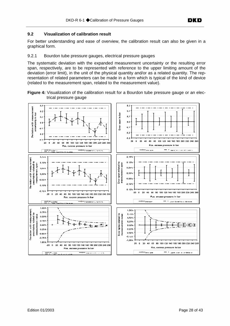
The systematic deviation with the expanded measurement uncertainty or the resulting errorspan, respectively, are to be represented with reference to the upper limiting amount of thedeviation (error limit), in the unit of the physical quantity and/or as a related quantity. The rep-resentation of related parameters can be made in a form which is typical of the kind of device(related to the measurement span, related to the measurement value).
Figure 4: Visualization of the calibration result for a Bourdon tube pressure gauge or an elec-trical pressure gauge
����
����
����
���
���
���
���
��� � �� �� �� �� ��� ��� ��� ��� ��� ��� ��� ��� ���
2QU� GZEGUU RTGUUWTG KP DCT
&GXKCVKQPYKVJOGCUWTGOGPV
WPEGTVCKPV[
KPDCT
FGXKCVKQP OGCUWTGOGPV WPEGTVCKPV[WRRGT� NQYGT NKOKV QH FGXKCVKQP
����
����
����
���
���
���
���
��� � �� �� �� �� ��� ��� ��� ��� ��� ��� ��� ��� ���
2QU� GZEGUU RTGUUWTG KP DCT
'TTQTURCPKP
DCT
GTTQT URCP WRRGT� NQYGT NKOKV QH FGXKCVKQP
������
������
������
�����
�����
�����
�����
��� � �� �� �� �� ��� ��� ��� ��� ��� ��� ��� ��� ���
2QU� GZEGUU RTGUUWTG KP DCT
&GXKCVKQPYKVJOGCUWTGOGPV
WPEGTVCKPV[
TGNCVGFVQ
OGCUWTGOGPVURCP
FGXKCVKQP OGCUWTGOGPV WPEGTVCKPV[WRRGT� NQYGT NKOKV QH FGXKCVKQP
������
������
������
�����
�����
�����
�����
��� � �� �� �� �� ��� ��� ��� ��� ��� ��� ��� ��� ���
2QU� GZEGUU RTGUUWTG KP DCT
'TTQTURCPTGNCVGFVQ
OGCUWTGOGPVURCP
GTTQT URCP WRRGT� NQYGT NKOKV QH FGXKCVKQP
������
������
������
������
�����
�����
�����
�����
�����
��� � �� �� �� �� ��� ��� ��� ��� ��� ��� ��� ��� ���
2QU� GZEGUU RTGUUWTG KP DCT
&GXKCVKQPYKVJOGCUWTGOGPV
WPEGTVCKPV[
TGNCVGFVQ
OGCUWTGOGPVXCNWG
FGXKCVKQP OGCUWTGOGPV WPEGTVCKPV[WRRGT� NQYGT NKOKV QH FGXKCVKQP
������
������
������
������
�����
�����
�����
�����
�����
��� � �� �� �� �� ��� ��� ��� ��� ��� ��� ��� ��� ���
2QU� GZEGUU RTGUUWTG KP DCT
'TTQTURCPTGNCVGFVQ
OGCUWTGOGPVXCNWG
GTTQT URCP WRRGT� NQYGT NKOKV QH FGXKCVKQP
DKD-R 6-1 ◆ Calibration of Pressure Gauges
Edition 01/2003 Page 29 of 43
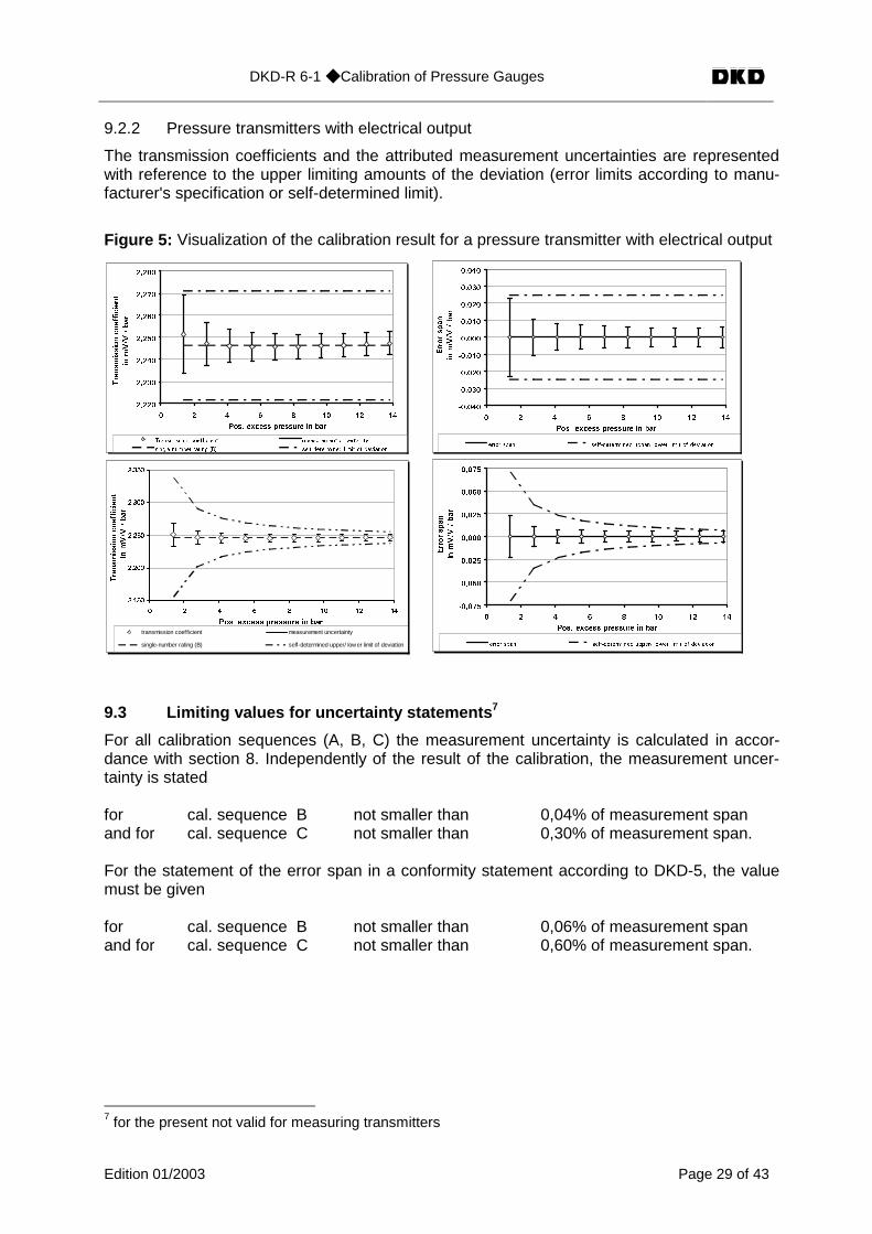
9.2.2 Pressure transmitters with electrical output
The transmission coefficients and the attributed measurement uncertainties are representedwith reference to the upper limiting amounts of the deviation (error limits according to manu-facturer's specification or self-determined limit).
Figure 5: Visualization of the calibration result for a pressure transmitter with electrical output
�����
�����
�����
�����
�����
�����
�����
� � � � � �� �� ��
2QU� GZEGUU RTGUUWTG KP DCT
6TCPUOKUUKQPEQGHHKEKGPV
KPO8�8
�DCT
6TCPUOKUUKQP EQGHHKEKGPV OGCUWTGOGPV WPEGTVCKPV[
UKPING�PWODGT TCVKPI $� UGNH�FGVGTOKPGF NKOKV QH FGXKCVKQP
������
������
������
������
�����
�����
�����
�����
�����
� � � � � �� �� ��
2QU� GZEGUU RTGUUWTG KP DCT
'TTQTURCP
KPO8�8
�DCT
GTTQT URCP UGNH�FGVGTOKPGF WRRGT� NQYGT NKOKV QH FGXKCVKQP
�����
�����
�����
�����
�����
� � � � � �� �� ��
2QU� GZEGUU RTGUUWTG KP DCT
6TCPUOKUUKQPEQGHHKEKGPV
KPO8�8
�DCT
trans mis s ion coefficient meas urement uncertainty
s ingle-number rating (B) s elf-determined upper/ lower limit of deviation
������
������
������
�����
�����
�����
�����
� � � � � �� �� ��
2QU� GZEGUU RTGUUWTG KP DCT
'TTQTURCP
KPO8�8
�DCT
GTTQT URCP UGNH�FGVGTOKPGF WRRGT� NQYGT NKOKV QH FGXKCVKQP
9.3 Limiting values for uncertainty statements 7
For all calibration sequences (A, B, C) the measurement uncertainty is calculated in accor-dance with section 8. Independently of the result of the calibration, the measurement uncer-tainty is stated
for cal. sequence B not smaller than 0,04% of measurement spanand for cal. sequence C not smaller than 0,30% of measurement span.
For the statement of the error span in a conformity statement according to DKD-5, the valuemust be given
for cal. sequence B not smaller than 0,06% of measurement spanand for cal. sequence C not smaller than 0,60% of measurement span.
7 for the present not valid for measuring transmitters
DKD-R 6-1 ◆ Calibration of Pressure Gauges
Edition 01/2003 Page 30 of 43
10. Other rules and standards
If appropriate, the following rules are to be taken into account for the calibration of pressuregauges. It may also be agreed to carry out the calibration in accordance with individual sec-tions of some of these rules.
EN 837 part 1 Druckmeßgeräte mit RohrfedernMaße, Meßtechnik, Anforderungen und Prüfung(Pressure gauges with Bourdon tubes; measures, measuringtechnique, requirements and test)February 1997 edition
EN 837 part 3 Druckmeßgeräte mit Platten- und KapselfedernMaße, Meßtechnik, Anforderungen und Prüfung(Pressure gauges with diaphragm and capsule elements;measures, measuring technique, requirements and test)February 1997 edition
DIN 16086 Elektrische DruckmeßgeräteDruckaufnehmer, Druckmeßumformer, DruckmeßgeräteBegriffe und Angaben in Datenblättern(Electrical pressure gauges; pressure transducers, pressuretransmitters, pressure gauges; terms and statements in datasheets)May 1992 edition
DIN 43790 Grundregeln für die Gestaltung von Strichskalen und Zeigern(Basic rules for the design of line scales and pointers)January 1991 edition
EA-10/03 Calibration of Pressure BalancesEdition 1, July 1997
DKD-R 3-6 Richtlinie zur Auswahl und Kalibrierung von elektrischenReferenzdruckmeßgeräten für die Anwendung inDKD-Laboratorien(Guideline for the selection and calibration of electrical refer-ence pressure gauges for use in DKD laboratories)November 1993 edition
EA – 10/17 EA Guidelines on the Calibration of ElectromechanicalManometers (rev. 00)July 2002

DKD-R 6-1 ◆ Calibration of Pressure Gauges
Edition 01/2003 Page 31 of 43
Annex A Estimate of measurement uncertainty to be attributed to the values ofthe pressure balance under conditions of use 8
The values and the attributed expanded uncertainty U standard, ref for a pressure balance underreference conditions are to be taken from the calibration certificate (issued, for example, bythe PTB). When the instrument is used under conditions of use, corrections for the relevantinfluence quantities are to be applied to the values and to these values, too, an uncertaintyhas to be attributed.
Evaluation model 9:
( ) ( ) ( )
1
0
a1,
1 1 2 0 C
n
i
e
m gi
m ip g h
A p t
ρ
ρρ
λ α β
=
+
⋅ ⋅ −∑ = ∆ ⋅ ⋅
⋅ + ⋅ ⋅ + + ⋅ − ° (31)
Fl aρ ρ ρ∆ = − (32)
Uncertainty analysis
with the influence quantities relevant to the pressure value of the standard: temperature,thermal linear expansion coefficient of piston and cylinder, acceleration due to gravity anddeformation coefficient. The sensitivity coefficients were calculated with the approximationsusual for practical applications and for the most common case α = β .
Table 9
Quantity
Xi
Esti-mate
xi
Half-width
a
Probabilitydistribution
P(xi)
Divisor
Standarduncertainty
u(xi)
Sensitivity coefficient
ci
Uncertaintycontribution
ui(y)
Unit
Temperature tK at rectangle 3 ( ) 21
3 tu t a= ⋅ ct = - 2⋅α⋅p ut = ct⋅ u(t) bar
Thermallinear
expansioncoefficient
α+β αa rectangle 3 ( ) 21
3u aαα = ⋅ cα= -2⋅(t - 20°C)⋅p uα = cα⋅ u(α) bar
Accelerationdue togravity
g ga rectangle 3 ( ) 21
3 gu g a= ⋅ cg = p /g ug = cg⋅ u(g) bar
Deformationcoefficient λ aλ rectangle 3 ( ) 21
3u aλλ = ⋅ cλ = - p2 uλ = cλ⋅ u(λ) bar
Y y 2�
2g
2.
2t1corr uuuuu +++= bar
8 cf. 3 on page 179 cf. also EA-10/03 Annex B
DKD-R 6-1 ◆ Calibration of Pressure Gauges
Edition 01/2003 Page 32 of 43
Note:1. In calibration certificates issued by the PTB for pressure balances, the contribution of the
uncertainty of the numerical value of the deformation coefficient to the uncertainty of thepressure measurement at reference temperature generally has already been taken intoaccount.
2. Portable measuring instruments allow the local acceleration due to gravity at a certain lo-cation to be measured with a relative uncertainty of a few ppm. If such an exact measure-ment value is available, it may be permissible to neglect the uncertainty contribution of theacceleration due to gravity as the relative uncertainty of the value of the cross sectionalarea is in most cases substantially higher.
3. Related to the force of inertia g⋅m acting in the vacuum, the buoyancy correction is of theorder of 1,5⋅10-4. Changes in the air density at a particular location due to the weathernormally do not exceed 2 % corresponding to a relative contribution to the measurementuncertainty of 3 ppm. In relation to the uncertainty of the cross sectional area of 50 ppmusually given in calibration certificates, this contribution is negligible and generally does notjustify the metrological efforts made to determine it (cf. 6 Ambient conditions, Note).
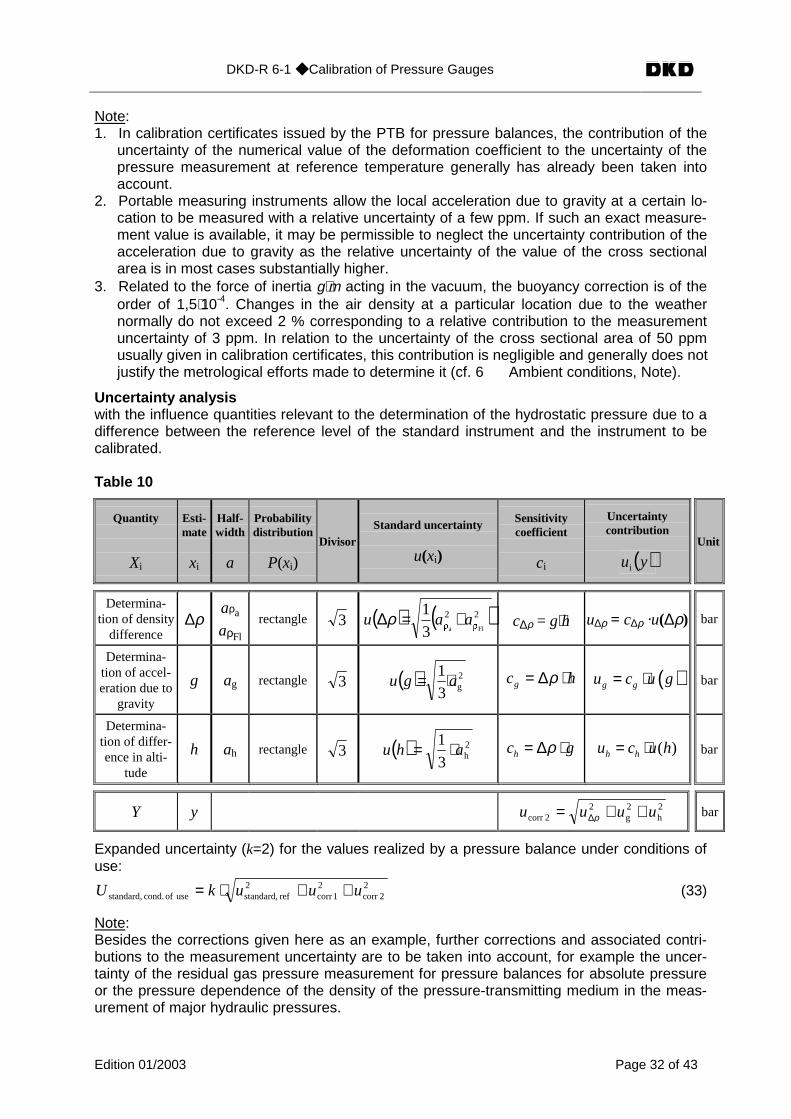
Uncertainty analysiswith the influence quantities relevant to the determination of the hydrostatic pressure due to adifference between the reference level of the standard instrument and the instrument to becalibrated.
Table 10
Quantity
Xi
Esti-mate
xi
Half-width
a
Probabilitydistribution
P(xi)Divisor
Standard uncertainty
u(xi)
Sensitivitycoefficient
ci
Uncertaintycontribution
( )yui
Unit
Determina-tion of density
difference∆ρ
aρa
aρFl
rectangle 3 ( ) ( )2!
2! Fla3
1aau +=∆ρ c∆ρ = g⋅h u∆ρ = c∆ρ ·u(∆ρ) bar
Determina-tion of accel-eration due to
gravity
g ag rectangle 3 ( ) 2g3
1agu ⋅= gc hρ= ∆ ⋅ ( )g gu c u g= ⋅ bar
Determina-tion of differ-ence in alti-
tude
h ah rectangle 3 ( ) 2h3
1ahu ⋅= hc gρ= ∆ ⋅ ( )h hu c u h= ⋅ bar
Y y 2h
2g
22corr uuuu ++= ∆ρ bar
Expanded uncertainty (k=2) for the values realized by a pressure balance under conditions ofuse:
22corr
21corr
2ref standard,use of cond. standard, uuukU ++⋅= (33)
Note:Besides the corrections given here as an example, further corrections and associated contri-butions to the measurement uncertainty are to be taken into account, for example the uncer-tainty of the residual gas pressure measurement for pressure balances for absolute pressureor the pressure dependence of the density of the pressure-transmitting medium in the meas-urement of major hydraulic pressures.
DKD-R 6-1 ◆ Calibration of Pressure Gauges
Edition 01/2003 Page 33 of 43
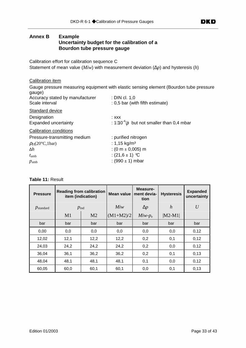
Annex B ExampleUncertainty budget for the calibration of aBourdon tube pressure gauge
Calibration effort for calibration sequence CStatement of mean value (Miw) with measurement deviation (∆p) and hysteresis (h)
Calibration itemGauge pressure measuring equipment with elastic sensing element (Bourdon tube pressuregauge)Accuracy stated by manufacturer : DIN cl. 1,0Scale interval : 0,5 bar (with fifth estimate)
Standard deviceDesignation : xxxExpanded uncertainty : 1⋅10-4⋅p but not smaller than 0,4 mbar
Calibration conditionsPressure-transmitting medium : purified nitrogenρFl(20°C,1bar) : 1,15 kg/m³∆h : (0 m ± 0,005) mtamb : (21,6 ± 1) °Cpamb : (990 ± 1) mbar
Table 11: Result
PressureReading from calibration
item (indication) Mean valueMeasure-
ment devia-tion
HysteresisExpanded
uncertainty
pstandard pind Miw ∆p h U
M1 M2 (M1+M2)/2 Miw-pe |M2-M1|
bar bar bar bar bar bar bar
0,00 0,0 0,0 0,0 0,0 0,0 0,12
12,02 12,1 12,2 12,2 0,2 0,1 0,12
24,03 24,2 24,2 24,2 0,2 0,0 0,12
36,04 36,1 36,2 36,2 0,2 0,1 0,13
48,04 48,1 48,1 48,1 0,1 0,0 0,12
60,05 60,0 60,1 60,1 0,0 0,1 0,13

DKD-R 6-1 ◆ Calibration of Pressure Gauges
Edition 01/2003 Page 34 of 43
Table 12: Uncertainty budget for load step p=60,05 bar
QuantityEsti-mate
Width ofdistribu-
tionDivisor
Uncer-tainty
Sensitivitycoefficient
Uncer-tainty
contrib.Variance
Xi xi 2a u(xi) ci u(y) u2
bar bar²
pstandard60,05bar
2 3,00*10-3 bar -1 3,00*10-3 9,02*10-6
pstandard, t 0,999997 2 K 3 5,77*10-1 K -1,32*10-3
bar/K7,63*10-4 5,82*10-7
pstandard, h * 0 1,0*10-2 m 3 2,89*10-3 m -6,74*10-3
bar/m1,95*10-5 3,79*10-10
pind60,05bar
0,1 bar 3 5,77*10-2 bar 1 5,77*10-2 3,33*10-3
δpzero deviation 0 0,0 bar 3 0 1 0 0
δprepeatability 0 0,0 bar 3 0 1 0 0
δphysteresis 0 0,1 bar 3 2,89*10-2 bar 1 2,89*10-2 8,33*10-4
∆p 0,00 bar u = 6,46*10-22 34,17*10iu
−=∑
∆p 0,00 bar U = k⋅u (k = 2) 0,13 bar
*allowing for the pressure-dependent gas density (approximation)
( )( )
+⋅
+⋅⋅°=
tT
Tp
bar1
K20abs
C,1bar20tp,ρρ with T=273,15K
For the correction of the pressures realized by the standard device, the following data wereused (calculation in accordance with Annex A):
tK : (21,6 ± 1) °Cg : (9,812533 ± 0,000020)*10-6 m⋅s-²α+β : (11 ± 1,1)*10-6 K-1
Note:The calculated expanded measurement uncertainty of U = 0,13 bar for the load stepp = 60,05 bar corresponds to a relative expanded uncertainty of W = 0,22%. According to sec-tion 10.3: Limiting values for uncertainty statements, the value stated in the calibration certifi-cate for a calibration according to sequence C (repeatability and reproducibility cannot be de-termined) must not be smaller than a value of W = 0,30%, corresponding to an expanded un-certainty of U = 0,18 bar .
DKD-R 6-1 ◆ Calibration of Pressure Gauges
Edition 01/2003 Page 35 of 43
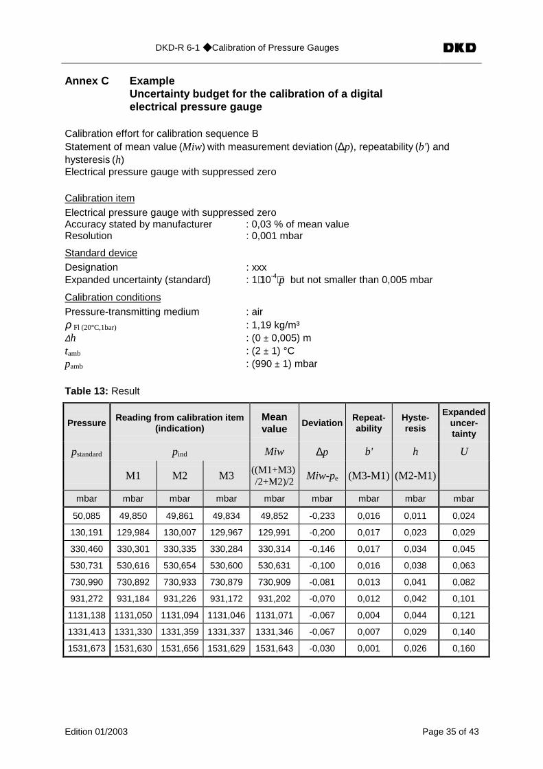
Annex C ExampleUncertainty budget for the calibration of a digitalelectrical pressure gauge
Calibration effort for calibration sequence BStatement of mean value (Miw) with measurement deviation (∆p), repeatability (b') andhysteresis (h)Electrical pressure gauge with suppressed zero
Calibration itemElectrical pressure gauge with suppressed zeroAccuracy stated by manufacturer : 0,03 % of mean valueResolution : 0,001 mbar
Standard deviceDesignation : xxxExpanded uncertainty (standard) : 1⋅10-4⋅p but not smaller than 0,005 mbar
Calibration conditionsPressure-transmitting medium : airρ Fl (20°C,1bar) : 1,19 kg/m³∆h : (0 ± 0,005) mtamb : (2 ± 1) °Cpamb : (990 ± 1) mbar
Table 13: Result
PressureReading from calibration item
(indication)Meanvalue
DeviationRepeat-ability
Hyste-resis
Expandeduncer-tainty
pstandard pind Miw ∆p b' h U
M1 M2 M3((M1+M3)/2+M2)/2
Miw-pe (M3-M1) (M2-M1)
mbar mbar mbar mbar mbar mbar mbar mbar mbar
50,085 49,850 49,861 49,834 49,852 -0,233 0,016 0,011 0,024
130,191 129,984 130,007 129,967 129,991 -0,200 0,017 0,023 0,029
330,460 330,301 330,335 330,284 330,314 -0,146 0,017 0,034 0,045
530,731 530,616 530,654 530,600 530,631 -0,100 0,016 0,038 0,063
730,990 730,892 730,933 730,879 730,909 -0,081 0,013 0,041 0,082
931,272 931,184 931,226 931,172 931,202 -0,070 0,012 0,042 0,101
1131,138 1131,050 1131,094 1131,046 1131,071 -0,067 0,004 0,044 0,121
1331,413 1331,330 1331,359 1331,337 1331,346 -0,067 0,007 0,029 0,140
1531,673 1531,630 1531,656 1531,629 1531,643 -0,030 0,001 0,026 0,160

DKD-R 6-1 ◆ Calibration of Pressure Gauges
Edition 01/2003 Page 36 of 43
Table 14: Uncertainty budget for load step p=1531,673 mbar
Quantity EstimateWidth ofdistribu-
tionDivisor Uncertainty
Sensitiv-ity coeffi-
cient
Uncertaintycontribu-
tionVariance
X xi 2a u(xi) ci u(y) 2u
mbar mbar²
pstandard1531,673
mbar 2 7,66*10-2
mbar-1 7,66*10-2 5,87*10-3
pstandard, t 0,999997 2 K 3 5,77*10-1 K -3,37*10-2
mbar/K1,95*10-2 3,78*10-4
pstan-
dard,residual0 2
1,00*10-2
mbar 1 1,00*10-2 1,00*10-4
pstandard, h* 0 1,0*10-2 m 3 2,89*10-3 m -1,78*10-1
mbar/m5,14*10-4 2,64*10-7
pind1531,643
mbar 0,001 mbar 32,89*10-4
mbar1 2,89*10-4 8,33*10-8
δpzero
deviation0 0,000 mbar 3 0 1 0 0
δpre-
peatability0 0,001 mbar 3
2,89*10-4
mbar 1 2,89*10-4 8,33*10-8
δphysteresis 0 0,026 mbar 37,51*10-3
mbar1 7,51*10-3 5,63*10-5
∆p-0,030mbar
u = 8,00*10-22 36,40*10iu
−=∑
∆p-0,030mbar ( 2)
U k u
k
= ⋅=
0,160 mbar
* allowing for the pressure-dependent gas density (approximation)
( )( )
+⋅
+⋅⋅°=
tT
Tp
tp bar1
K20abs
C,1bar20,ρρ with T=273,15K
For the correction of the pressures realized by the standard device, the following data wereused (calculation according to Annex A):
tK : 21,6 ± 1) °Cg : (9,812533 ± 0,000020) )⋅10-6 m⋅s-²α+β : (11 ± 1,1)⋅10-6 K-1
Note:The calculated expanded uncertainty of U = 0,160 mbar for the load step p = 1531,673 mbarcorresponds to a relative expanded uncertainty of W = 0,01%. According to section 10.3: Lim-iting values for uncertainty statements, the value stated in the calibration certificate for a cali-bration according to sequence B must not be smaller than a value of W = 0,04%, correspond-ing to an expanded uncertainty of U = 0,613 mbar .
DKD-R 6-1 ◆ Calibration of Pressure Gauges
Edition 01/2003 Page 37 of 43
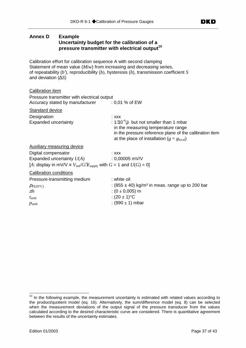
Annex D ExampleUncertainty budget for the calibration of apressure transmitter with electrical output 10
Calibration effort for calibration sequence A with second clampingStatement of mean value (Miw) from increasing and decreasing series,of repeatability (b'), reproducibility (b), hysteresis (h), transmission coefficient Sand deviation (∆S)
Calibration itemPressure transmitter with electrical outputAccuracy stated by manufacturer : 0,01 % of EW
Standard deviceDesignation : xxxExpanded uncertainty : 1⋅10-4⋅p but not smaller than 1 mbar
in the measuring temperature range in the pressure reference plane of the calibration item at the place of installation (g = glocal)
Auxiliary measuring deviceDigital compensator : xxxExpanded uncertainty U(A) : 0,00005 mV/V[A: display in mV/V ≡ Vind/G⋅Vsupply with G = 1 and U(G) = 0]
Calibration conditionsPressure-transmitting medium : white oilρFl(20°C) : (855 ± 40) kg/m³ in meas. range up to 200 bar∆h : (0 ± 0,005) mtamb : (20 ± 1)°Cpamb : (990 ± 1) mbar
10 In the following example, the measurement uncertainty is estimated with related values according tothe product/quotient model (eq. 16). Alternatively, the sum/difference model (eq. 8) can be selectedwhen the measurement deviations of the output signal of the pressure transducer from the valuescalculated according to the desired characteristic curve are considered. There is quantitative agreementbetween the results of the uncertainty estimates.
DKD-R 6-1 ◆ Calibration of Pressure Gauges
Edition 01/2003 Page 38 of 43
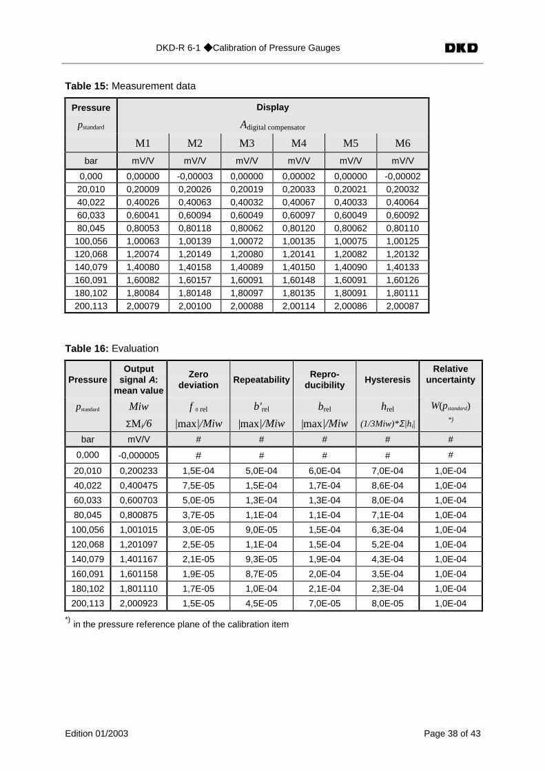
Table 15: Measurement data
Pressure
pstandard
Display
Adigital compensator
M1 M2 M3 M4 M5 M6
bar mV/V mV/V mV/V mV/V mV/V mV/V
0,000 0,00000 -0,00003 0,00000 0,00002 0,00000 -0,0000220,010 0,20009 0,20026 0,20019 0,20033 0,20021 0,2003240,022 0,40026 0,40063 0,40032 0,40067 0,40033 0,4006460,033 0,60041 0,60094 0,60049 0,60097 0,60049 0,6009280,045 0,80053 0,80118 0,80062 0,80120 0,80062 0,80110100,056 1,00063 1,00139 1,00072 1,00135 1,00075 1,00125120,068 1,20074 1,20149 1,20080 1,20141 1,20082 1,20132140,079 1,40080 1,40158 1,40089 1,40150 1,40090 1,40133160,091 1,60082 1,60157 1,60091 1,60148 1,60091 1,60126180,102 1,80084 1,80148 1,80097 1,80135 1,80091 1,80111200,113 2,00079 2,00100 2,00088 2,00114 2,00086 2,00087
Table 16: Evaluation
PressureOutput
signal A:mean value
Zerodeviation Repeatability
Repro-ducibility Hysteresis
Relativeuncertainty
pstandard Miw f 0 rel b'rel brel hrel W(pstandard)
ΣM i/6 |max|/Miw |max|/Miw |max|/Miw (1/3Miw)*Σ|hi|*)
bar mV/V # # # # #
0,000 -0,000005 # # # # #
20,010 0,200233 1,5E-04 5,0E-04 6,0E-04 7,0E-04 1,0E-04
40,022 0,400475 7,5E-05 1,5E-04 1,7E-04 8,6E-04 1,0E-04
60,033 0,600703 5,0E-05 1,3E-04 1,3E-04 8,0E-04 1,0E-04
80,045 0,800875 3,7E-05 1,1E-04 1,1E-04 7,1E-04 1,0E-04
100,056 1,001015 3,0E-05 9,0E-05 1,5E-04 6,3E-04 1,0E-04
120,068 1,201097 2,5E-05 1,1E-04 1,5E-04 5,2E-04 1,0E-04
140,079 1,401167 2,1E-05 9,3E-05 1,9E-04 4,3E-04 1,0E-04
160,091 1,601158 1,9E-05 8,7E-05 2,0E-04 3,5E-04 1,0E-04
180,102 1,801110 1,7E-05 1,0E-04 2,1E-04 2,3E-04 1,0E-04
200,113 2,000923 1,5E-05 4,5E-05 7,0E-05 8,0E-05 1,0E-04
*) in the pressure reference plane of the calibration item

DKD-R 6-1 ◆ Calibration of Pressure Gauges
Edition 01/2003 Page 39 of 43
Table 17: Result
Pressure Transmissioncoefficient
Deviation Rel. expandeduncertainty
Expandeduncertainty
Error span
pstandard S ∆S W(S) U(S) U´(S)
Miw/p S – S' 2[Σwi2(S)]0,5 W⋅S U + ∆S
bar (mV/V)/bar (mV/V)/bar # (mV/V)/bar (mV/V)/bar
0,000 # # # # #
20,010 0,01000666 0,00000515 6,7E-04 0,00000668 0,00001183
40,022 0,01000637 0,00000486 5,4E-04 0,00000539 0,00001025
60,033 0,01000622 0,00000471 4,9E-04 0,00000493 0,00000964
80,045 0,01000531 0,00000380 4,4E-04 0,00000438 0,00000818
100,056 0,01000455 0,00000304 3,9E-04 0,00000394 0,00000698
120,068 0,01000347 0,00000196 3,3E-04 0,00000335 0,00000531
140,079 0,01000269 0,00000118 3,0E-04 0,00000297 0,00000415
160,091 0,01000155 0,00000004 2,6E-04 0,00000259 0,00000263
180,102 0,01000050 -0,00000101 2,1E-04 0,00000215 0,00000316
200,113 0,00999897 -0,00000254 1,2E-04 0,00000123 0,00000377
Single-number rating:S' = 0,01000151 (mV/V) / bar
Table 18: Uncertainty budget for load step p=100,056 bar
Quantity EstimateWidth ofdistribu-
tionDivisor
Uncer-tainty
Sensitiv-ity coeffi-
cient
Uncertaintycontrib-
utionVariance
Xi xi 2a w(xi) ci wi(y) wi2
pstandard100,056
bar20 mbar 2 5,00*10-5 -1 5,00*10-5 2,50*10-9
Vind1,001015
mV/V0,00010
mV/V2 2,50*10-5 1 2,50*10-5 6,25*10-10
Kzero deviation 1 3,0*10-53 8,66*10-6 1 8,66*10-6 7,50*10-11
Krepeatability 1 9,0*10-53 2,60*10-5 1 2,60*10-5 6,76*10-10
Kreproducibility 1 1,5*10-43 4,33*10-5 1 4,33*10-5 1,87*10-9
Khysteresis 1 6,3*10-43 1,82*10-4 1 1,82*10-4 3,31*10-8
S 0,01000455 w = 1,97⋅10-4 Σwi2 = 3,88⋅10-8
S 0,01000455 ( )2 =⋅= kwkW 3,9*10-4
The pressure dependence of the oil density has been neglected.
DKD-R 6-1 ◆ Calibration of Pressure Gauges
Edition 01/2003 Page 40 of 43
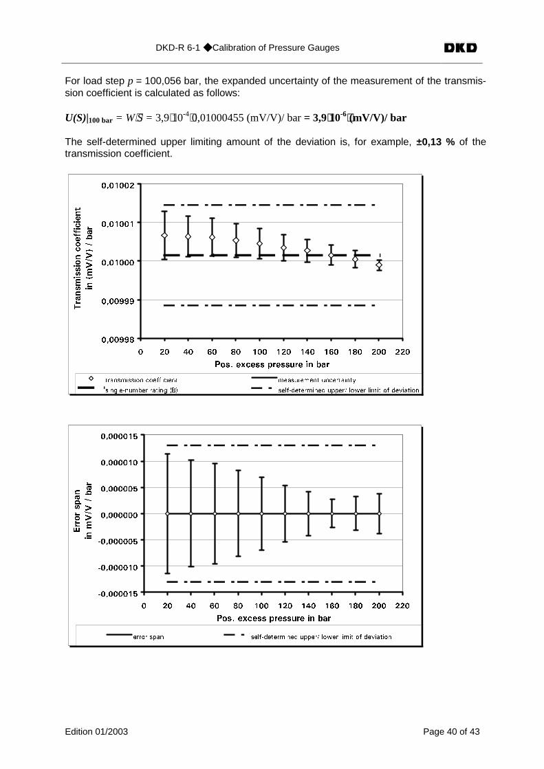
For load step p = 100,056 bar, the expanded uncertainty of the measurement of the transmis-sion coefficient is calculated as follows:
U(S)|100 bar = W⋅S = 3,9⋅10-4⋅0,01000455 (mV/V)/ bar = 3,9⋅10-6⋅(mV/V)/ bar
The self-determined upper limiting amount of the deviation is, for example, ±0,13 % of thetransmission coefficient.
�������
�������
�������
�������
�������
� �� �� �� �� ��� ��� ��� ��� ��� ��� ���
2QU� GZEGUU RTGUUWTG KP DCT
6TCPUOKUUKQPEQGHHKEKGPV
KPO
8�8
��DCT
VTCPUOKUUKQP EQGHHKEKGPV OGCUWTGOGPV WPEGTVCKPV[
UKPING�PWODGT TCVKPI $� UGNH�FGVGTOKPGF WRRGT� NQYGT NKOKV QH FGXKCVKQP
���������
���������
���������
��������
��������
��������
��������
� �� �� �� �� ��� ��� ��� ��� ��� ��� ���
2QU� GZEGUU RTGUUWTG KP DCT
'TTQTURCP
KPO8�8
�DCT
GTTQT URCP UGNH�FGVGTOKPGF WRRGT� NQYGT NKOKV QH FGXKCVKQP
DKD-R 6-1 ◆ Calibration of Pressure Gauges
Edition 01/2003 Page 41 of 43
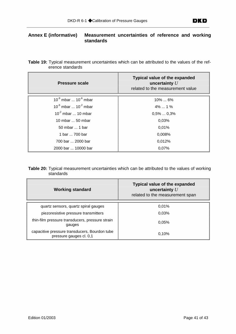
Annex E (informative) Measurement uncertainties of reference and workingstandards
Table 19: Typical measurement uncertainties which can be attributed to the values of the ref-erence standards
Pressure scaleTypical value of the expanded
uncertainty Urelated to the measurement value
10-9 mbar ... 10-6 mbar 10% ... 6%
10-6 mbar ... 10-2 mbar 4% ... 1 %
10-2 mbar ... 10 mbar 0,5% ... 0,3%
10 mbar ... 50 mbar 0,03%
50 mbar ... 1 bar 0,01%
1 bar ... 700 bar 0,008%
700 bar ... 2000 bar 0,012%
2000 bar ... 10000 bar 0,07%
Table 20: Typical measurement uncertainties which can be attributed to the values of workingstandards
Working standardTypical value of the expanded
uncertainty Urelated to the measurement span
quartz sensors, quartz spiral gauges 0,01%
piezoresistive pressure transmitters 0,03%
thin-film pressure transducers, pressure straingauges
0,05%
capacitive pressure transducers, Bourdon tubepressure gauges cl. 0,1
0,10%
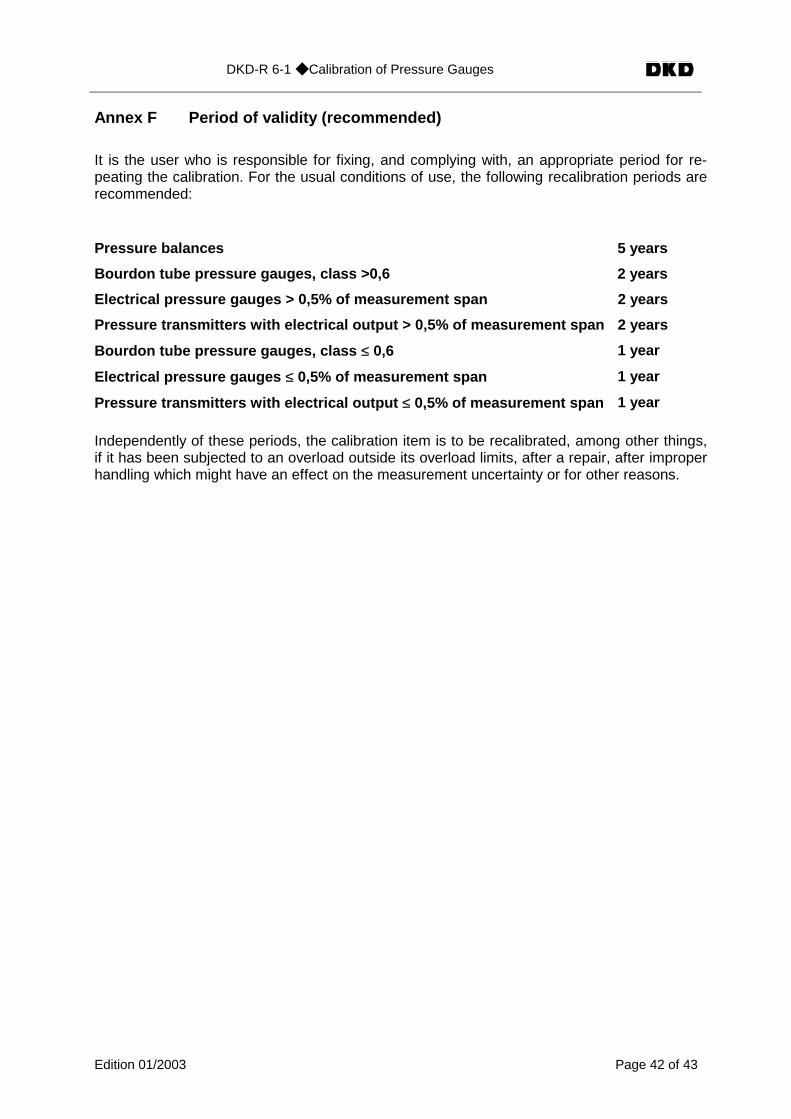
DKD-R 6-1 ◆ Calibration of Pressure Gauges
Edition 01/2003 Page 42 of 43
Annex F Period of validity (recommended)
It is the user who is responsible for fixing, and complying with, an appropriate period for re-peating the calibration. For the usual conditions of use, the following recalibration periods arerecommended:
Pressure balances 5 years
Bourdon tube pressure gauges, class >0,6 2 years
Electrical pressure gauges > 0,5% of measurement span 2 years
Pressure transmitters with electrical output > 0,5% of measurement span 2 years
Bourdon tube pressure gauges, class ≤ 0,6 1 year
Electrical pressure gauges ≤ 0,5% of measurement span 1 year
Pressure transmitters with electrical output ≤ 0,5% of measurement span 1 year
Independently of these periods, the calibration item is to be recalibrated, among other things,if it has been subjected to an overload outside its overload limits, after a repair, after improperhandling which might have an effect on the measurement uncertainty or for other reasons.

DKD-R 6-1 ◆ Calibration of Pressure Gauges
Edition 01/2003 Page 43 of 43
ReferencesDIN:Internationales Wörterbuch der MetrologieGerman version of International Vocabulary of Basic and General Terms in Metrology,2nd edition 1994, Beuth-Verlag, ISBN 3-410-13086-1
DIN 1319-1:Grundlagen der Meßtechnik, Teil 1: GrundbegriffeFundamentals of Metrology, part 1: Basic terms, 1996
DIN 1319-2:Grundlagen der Meßtechnik, Teil 2: Begriffe für die Anwendung von MeßgerätenFundamentals of Metrology, part 2: Terms for the use of measuring instruments, 1999
DKD-5:Anleitung zum Erstellen eines DKD-KalibrierscheinsInstructions for drawing up a DKD calibration certificate,DKD, edition 2002
The uncertainty analysis is based on the following documents:
ISO:Guide to the Expression of Uncertainty in Measurement1st edition 1993, ISO, Geneva, ISBN 92-67-10188-9
DIN V ENV 13005Leitfaden zur Angabe der Unsicherheit beim MessenGerman version of ENV 13005:1999
EA-4/02:Expression of the Uncertainty of Measurement in CalibrationDecember 1999
EA-10/03:Calibration of Pressure Balances, Annex BEdition 1, July 1997
DKD-3:Angabe der Meßunsicherheiten bei KalibrierungenDKD 1998, German version of publication EA-4/02: Expression of the Uncertainty of Meas-urement in Calibration
DKD-3-E1: Supplement 1Angabe der Meßunsicherheiten bei Kalibrierungen, BeispieleDKD 1998, German version of publication EA-4/02-S1: Expression of the Uncertainty ofMeasurement in Calibration, Examples
DIN 1319-3:Grundlagen der Meßtechnik, Teil 3: Auswertung von Messungen einer einzelnen Meßgröße,Meßunsicherheit
Fundamentals of Metrology, part 3: Evaluation of measurements of a single measurand,measurement uncertainty, 1996
DIN 1319-4:Grundlagen der Meßtechnik, Teil 4: Auswertung von Messungen, Meßunsicherheit
Fundamentals of Metrology, part 4: Evaluation of measurements, measurement uncertainty,1999