r-5 residential information sheet - 2015 code
TRANSCRIPT

Department of Development and Permits
306 Cedar Road Post Office Box 15225
Chesapeake, Virginia 23328-5225 Tel. (757) 382-6018, 6890
Fax. (757) 382-8448 Purpose: This form is intended to identify some the design requirements for the City and as an advisory for the 2015 code changes. The form also indicates items that will be checked in the field that may not be required on the plan submittal. Addi-tionally this form will provide information on important code sections/criteria to be aware of by contractors and designers.
* Red Font Indicates Significant 2015 Code Changes (Please note – Changes provided are Not all inclusive)* Climatic and Geographic Design Criteria
Ground Snow Load
*Wind Speed (mph)
Seismic Design
Weathering Concrete
Frost Line
Depth
Termites Ice Barrier Underlayment
Air Freez-ing Index
Mean Annual Temp
Heating Degree Days
10 PSF 115/120 Vult 89/93 Vasd
MPH A Moderate 12
inches Moderate to
heavy None Required 1500 or less
50 – 65 Degrees 3,421 Days
Winter Design Temp
Summer Design Temp
Flood Zone AE
Decay Wood
Rainfall Design
Radon Areas
Shrink Swell Soils
Noise Zones
Manufactured Housing Code
22 De-grees
91 dry 78 wet
Yes Several different areas Design flood height in-cludes 1.5 foot of free-board above base flood
height
Moderate to Severe
3.4 inches
Per Hour
No
Limited Based on Soil Re-
ports
Yes Fentress Airfield Area
Wind Zone: Zone II – 27 PSF Uplift Snow Load Ground: 10 PSF Climate: Zone 4 Non-marine
Climate Zone 3 (built 94 to 2008)
See the last page for instructions and requirements
RESIDENTIAL R-5 PLAN REVIEW AND CONSTRUCTION INFORMATION LIST
2015 IRC CODE
Building Codes and 2015 Building Code Changes
Design Criteria
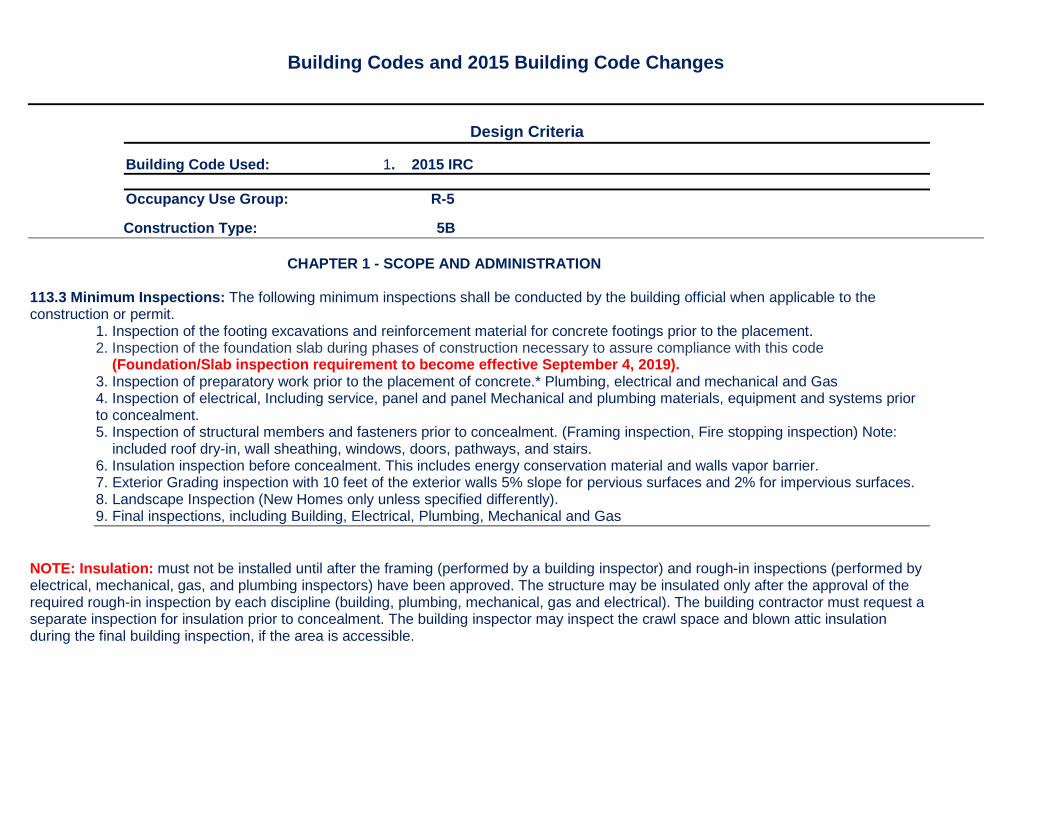
Building Code Used: 1. 2015 IRC
Occupancy Use Group: R-5 Construction Type: 5B CHAPTER 1 - SCOPE AND ADMINISTRATION 113.3 Minimum Inspections: The following minimum inspections shall be conducted by the building official when applicable to the construction or permit.
1. Inspection of the footing excavations and reinforcement material for concrete footings prior to the placement. 2. Inspection of the foundation slab during phases of construction necessary to assure compliance with this code (Foundation/Slab inspection requirement to become effective September 4, 2019). 3. Inspection of preparatory work prior to the placement of concrete.* Plumbing, electrical and mechanical and Gas 4. Inspection of electrical, Including service, panel and panel Mechanical and plumbing materials, equipment and systems prior to concealment. 5. Inspection of structural members and fasteners prior to concealment. (Framing inspection, Fire stopping inspection) Note: included roof dry-in, wall sheathing, windows, doors, pathways, and stairs. 6. Insulation inspection before concealment. This includes energy conservation material and walls vapor barrier. 7. Exterior Grading inspection with 10 feet of the exterior walls 5% slope for pervious surfaces and 2% for impervious surfaces. 8. Landscape Inspection (New Homes only unless specified differently). 9. Final inspections, including Building, Electrical, Plumbing, Mechanical and Gas
NOTE: Insulation: must not be installed until after the framing (performed by a building inspector) and rough-in inspections (performed by electrical, mechanical, gas, and plumbing inspectors) have been approved. The structure may be insulated only after the approval of the required rough-in inspection by each discipline (building, plumbing, mechanical, gas and electrical). The building contractor must request a separate inspection for insulation prior to concealment. The building inspector may inspect the crawl space and blown attic insulation during the final building inspection, if the area is accessible.
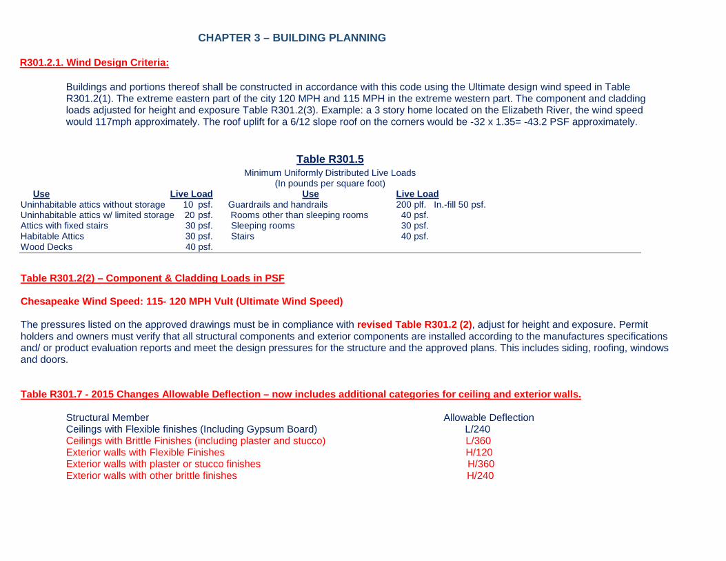
CHAPTER 3 – BUILDING PLANNING R301.2.1. Wind Design Criteria:
Buildings and portions thereof shall be constructed in accordance with this code using the Ultimate design wind speed in Table R301.2(1). The extreme eastern part of the city 120 MPH and 115 MPH in the extreme western part. The component and cladding loads adjusted for height and exposure Table R301.2(3). Example: a 3 story home located on the Elizabeth River, the wind speed would 117mph approximately. The roof uplift for a 6/12 slope roof on the corners would be -32 x 1.35= -43.2 PSF approximately.
Table R301.5
Minimum Uniformly Distributed Live Loads (In pounds per square foot)
Use Live Load Use Live Load Uninhabitable attics without storage 10 psf. Guardrails and handrails 200 plf. In.-fill 50 psf. Uninhabitable attics w/ limited storage 20 psf. Rooms other than sleeping rooms 40 psf. Attics with fixed stairs 30 psf. Sleeping rooms 30 psf. Habitable Attics 30 psf. Stairs 40 psf. Wood Decks 40 psf. Table R301.2(2) – Component & Cladding Loads in PSF Chesapeake Wind Speed: 115- 120 MPH Vult (Ultimate Wind Speed) The pressures listed on the approved drawings must be in compliance with revised Table R301.2 (2), adjust for height and exposure. Permit holders and owners must verify that all structural components and exterior components are installed according to the manufactures specifications and/ or product evaluation reports and meet the design pressures for the structure and the approved plans. This includes siding, roofing, windows and doors. Table R301.7 - 2015 Changes Allowable Deflection – now includes additional categories for ceiling and exterior walls.
Structural Member Allowable Deflection Ceilings with Flexible finishes (Including Gypsum Board) L/240 Ceilings with Brittle Finishes (including plaster and stucco) L/360 Exterior walls with Flexible Finishes H/120 Exterior walls with plaster or stucco finishes H/360 Exterior walls with other brittle finishes H/240

R302.1 Exterior walls. Construction, projections, openings and penetrations of exterior walls of dwellings and accessory buildings shall comply with Table R302.1 (1); or dwellings equipped throughout with an automatic sprinkler system installed in accordance with Section P2904 shall comply with Table R302.1(2).
Exception: # 7. This is a new item added to 2015 code that was not in the 2012 building code. Walls of dwellings and accessory struc-tures located on lots in subdivisions or zoning districts where building setbacks establish by local ordinance prohibit the walls of the structures on adjacent lots from being closer than 10 feet to each other at a point along the exterior walls.
R302.2.2 Parapet Exception: In townhouses or two family homes no penetration of the roof and sheathing including vents or plumbing vents within 4 feet of the common walls. R302.3 Two-family dwellings: This code section differs from the 2012 Code as it requires a 2 hour rated separation wall when a lot line separates each half of the duplex. R302.12 Floors draft stopping: In combustible construction where there is usable space both above and below the concealed space of a floor/ceiling assembly and that space exceeds 1000 sq. ft., draftstops must be installed so that the area of the concealed is divided into approximately equal areas. R303.4: Dwelling Units shall be provided with mechanical ventilation in accordance with Section M1507. R305.1 (Item 2) Minimum Height: The ceiling height above bathroom and toilet fixtures shall be such that the fixture is capable of being used for its intended purpose. A shower or tub equipped with a shower head shall have a ceiling height of not less than 6 foot 8 inches above an area of not less than 30”x30” at the showerhead. R308.4.2 Glazing adjacent to doors: This building code has been re-written and addition requirements have been added. Glazing in an individual fixed or operable panel adjacent to a door shall be considered to be a hazardous location where the bottom exposed edge of the glazing is less than 60 inches above the floor or walking surface and it meets either of the following conditions: 1. Where glazing is within 24 inches of either side of the door in the plane of the door in a closed position. 2. Where the glazing is on a wall perpendicular to the plane of the door in a closed position and within 24 inches of the hinge side of an in-swinging door. Exception #3 of the 2012 code has been removed from the code, which allowed a non- tempered glass door or window adjacent to the latch side of a swinging door. R308.4.5 Glazing and Wet Surfaces: Code has been reworded to eliminate the “exception” in the 2012 code. The code change now Incorporates safety glazing for glazing measured less than 60 inches horizontally in a straight line, from the water edge of a bath tub, hot tub, spa, whirlpool, or swimming pool. R308.4.7: Glazing adjacent to the bottom stair landing: Glazing adjacent to the landing at the bottom of a stairway where glazing is less than 36 inches above the landing and within 60 inch horizontal arc less than 180 degrees from the bottom tread nosing shall be considered a hazardous location. Exception: The glazing is protected by a guard complying with Section R312 and the pane of glass is more than 18inches from the guard. R310.1 Emergency escape and rescue openings: This section has been re-written for ease of reading and clarity. R311.3.1 Floor elevations at the egress door. Exception: The landing or floor on the exterior side shall not be more than 8-1/4 inches below the top of the threshold as long as the door does not swing over the dropped floor or landing.
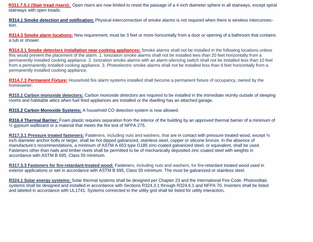
R311.7.5.1 (Stair tread risers): Open risers are now limited to resist the passage of a 4 inch diameter sphere in all stairways, except spiral stairways with open treads. R314.1 Smoke detection and notification; Physical interconnection of smoke alarms is not required when there is wireless interconnec-tion. R314.3 Smoke alarm locations: New requirement, must be 3 feet or more horizontally from a door or opening of a bathroom that contains a tub or shower. R314.3.1 Smoke detectors installation near cooking appliances: Smoke alarms shall not be installed in the following locations unless this would prevent the placement of the alarm. 1. Ionization smoke alarms shall not be installed lees than 20 feet horizontally from a permanently installed cooking appliance. 2. Ionization smoke alarms with an alarm-silencing switch shall not be installed less than 10 feet from a permanently installed cooking appliance. 3. Photoelectric smoke alarms shall not be installed less than 6 feet horizontally from a permanently installed cooking appliance. R314.7.3 Permanent Fixture: Household fire alarm systems installed shall become a permanent fixture of occupancy, owned by the homeowner. R315.1 Carbon monoxide detectors: Carbon monoxide detectors are required to be installed in the immediate vicinity outside of sleeping rooms and habitable attics when fuel fired appliances are installed or the dwelling has an attached garage. R315.2 Carbon Monoxide Systems; A household CO detection system is now allowed. R316.4 Thermal Barrier; Foam plastic requires separation from the interior of the building by an approved thermal barrier of a minimum of ½ gypsum wallboard or a material that meets the fire test of NFPA 275. R317.3.1 Pressure treated fasteners: Fasteners, including nuts and washers, that are in contact with pressure treated wood, except ½ inch diameter anchor bolts or larger, shall be hot dipped galvanized, stainless steel, copper or silicone bronze. In the absence of manufacture’s recommendations, a minimum of ASTM A 653 type G185 zinc-coated galvanized steel, or equivalent, shall be used. Fasteners other than nails and timber rivets shall be permitted to be of mechanically deposited zinc coated steel with weights in accordance with ASTM B 695, Class 55 minimum. R317.3.3 Fasteners for fire-retardant-treated wood: Fasteners, including nuts and washers, for fire-retardant treated wood used in exterior applications or wet in accordance with ASTM B 695, Class 55 minimum. The must be galvanized or stainless steel. R324.1 Solar energy systems: Solar thermal systems shall be designed per Chapter 23 and the International Fire Code. Photovoltaic systems shall be designed and installed in accordance with Sections R324.3.1 through R324.6.1 and NFPA 70. Inverters shall be listed and labeled in accordance with UL1741. Systems connected to the utility grid shall be listed for utility interaction.

R326.1.1 Changes to the ISPSC: The following changes shall be made to the ISPSC: Section 305.2.9 Equipment clear zone. Equipment, including pool equipment such as pumps, filters, and heating equipment shall not be located within 36 inches of the of the pool barrier when located on the same property. R329 Sound Transmission: See Noise Zone information R330.1 Kitchen areas: In dwellings without an approved fire sprinkler system, a fire extinguisher having a rating of 2-A:10-B:C shall be installed in the kitchen area. R331 through R331.6: Interior Passage: This Section applies to new dwellings that have both a kitchen and living area on the same floor level as the as the egress door as required by R311.2. This section is not applicable to additions, reconstruction, alterations or repairs. This code requires an accessible route on the first floor if this floor is on the same level as the means mail means of egress. An accessible route shall be maintained though-out the first floor or the same level as the main egress door. The egress level shall be equipped with 34 inch wide doors or openings to the kitchen, living areas, at least one bedroom, bathroom, and opening widths along the interior passage route. R311.1 General: This section applies to new dwelling units that have both a kitchen and a living area on the same floor level as the Egress Door required by Section R311.2. This section is not applicable to additions, reconstruction, alterations, or repair. R311.2 Kitchen: One interior passage route from the egress door to the kitchen shall comply with R331.6 R331.4 Bedroom: Where the dwelling unit has a bedroom on same floor as the egress door, one interior passage route from the egress door to at least one bedroom shall comply with R331.6 R331.5 Bathroom: Where a dwelling unit has a bathroom on the same floor level as the egress door, and the bathroom contains a water closet, lavatory, and a bathtub, or shower, one interior passage route from the egress door to at least one bathroom shall comply with R331.6. Bathroom fixture clearances shall comply with R307 and access to fixtures is not required to comply with R331.6 R331.6 Opening Widths: 1) Cased openings shall provide a minimum 34-inch clear width. 2) Doors shall be a minimum 34-inch width. Double doors shall be a nominal 34- inch width. Double doors are permitted to be used to meet this requirement.
CHAPTER 4 - FOUNDATIONS

R404.1.1 Masonry Foundation Walls: Concrete or masonry foundation walls shall be designed in accordance with accepted engineering practice where either of the following conditions exist. 1. Walls are subject to hydrostatic pressures from ground water. 2. Walls supporting more than 48 inches or unbalanced backfill that do not have permanent lateral support at the top or Bottom. See Table R404.1.1 (1)(2)(3) for Plain Masonry foundation requirements for sizes, grout filled, and vertical rebar spacing and sizing. Horizontal rebar as required per Table R404.1.2(1) for concrete basement walls. R408.2 Opening for Under-Floor Ventilation: Where a Class 1 Vapor Barrier is installed, a required vent opening is not required to be within 3 feet of each corner, Provided that there is cross ventilation. Explanation: This change clears up when and where vents are required to be installed. “Bump outs” 3 feet or less do not require foundation vents in the corners when a vapor retarder is installed. R408.6 Crawl Finish Grade: The crawl space finish grade must be equal to or greater than the exterior grade level. CHAPTER 5 – FLOORS R502.5 Allowable Girder and Header Spans: Span tables for wood beams and girders were moved from Chapter 5 to Tables R602.7(1), (2) and (3). R502.6 & 802.6 Minimum bearing: Each joist, girder, rafter and ceiling joist must bear a minimum of 1-1/2 inches on wood or metal and 3 inches on masonry or concrete or an approved Joist hanger. Rafters or Ceiling joist bearing on masonry or concrete must be direct, or a sill plate of 2 inch nominal thickness and shall provide a minimum nominal bearing area of 48 square inches. R507.2 Deck Ledger Connection to a Band Joist: Clarification: The deck ledger section has been re-organized to better describe the minimum requirements for the connection of deck ledgers to the band joist. CHAPTER 6 – WALL CONSTRUCTION R602.3 Exterior studs continuous: Exterior walls of wood frame construction shall have studs that are continuous from a support at the bottom plate to a support at the top plate to resist loads perpendicular to the wall. The support shall be a foundation or floor, ceiling or roof diaphragm. R602.3 Exterior studs continuous: Exterior walls of wood frame construction shall have studs that are continuous from a support at the bottom plate to a support at the top plate to resist loads perpendicular to the wall. The support shall be a foundation or floor, ceiling or roof diaphragm. Table R602.3.(1) Fastener Schedule for Structural Members: This table has been modified to reflect some new fastener spacing and location requirements for rafters to top plate connections, built up studs connections, abutting studs at corners and rim joist. R602.7 Headers: The girder and header span tables of Chapter 5 have been moved into Chapter 6 to the header section. Multi-ply single header tables are combined. A new section describing “Rim Board” headers has been added. R602.7.1 Single Member Headers: 2012 code did not specify the fasteners required for a single member headers. The 2015 Code specifies single headers be face nailed to the top and bottom of the header with 10 d Box nails spaced at 12 inches on center. R602.7.2 Rim Board Headers: Rim board headers size, material and span shall be in accordance with Table R602.7(1). Rim board headers shall be constructed in accordance with Figure R602.7.2 and shall be supported at each end by full height studs. The number of

full height studs at each end shall be not less than the number of studs displaced by half of the header span based on the maximum stud spacing in accordance with Table R602.3(5). Rim board headers supporting concentrated loads shall be designed in accordance with accepted engineering practices. R602.7 Header Tables: There are Virginia Amendments for two important tables in this Section. Table R602.7(1) - Girder and header spans for exterior bearing walls has been modified by Virginia Code and re-written. Table R602.7(2) – Girder and header spans for interior bear bearing walls have been modified by Virginia and re-written. R602.7.4 King Studs: Fasten each king stud with 4 12d nails. King studs are required at the end of a header. Table R602.7.5 Minimum number of full height studs at each end of headers in exterior walls: This is a new table in the code. When the wall framing studs are spaced 16 inches on center a 4 ft. long header requires 2 full height studs on each end of the header. And 8 ft. long header would require 3 full height studs and a 12 foot long header would require 5 full height studs. TABLE R602.10.3(1)+(2)+(3): These tables has braced wall major changes. 1. The table is now given in Ultimate wind speed. 2. The table now provides wind speeds in the < 110, 115,120,130, 140 MPH range. Table R602.12.4: This table is now calculated in Ultimate wind speed for required wall bracing. CHAPTER 7 – WALL COVERING R703.2 Cladding Vapor Barrier: An approved vapor barrier must be applied to the exterior sheathing behind all exterior cladding. R703.7.3.2 Masonry Veneer Lintels: New table was added to give minimum and maximum veneer height above the opening. R703.7.3.2 Masonry Veneer Anchorage: This table reflects revised spacing for veneer ties. R703.7.6 Brick or masonry weepholes: Weepholes must be provided in the outside wythe of masonry above the flashing and a maximum spacing of 33 inches on center and a minimum of 3/16 diameter. CHAPTER 8 - ROOF/CEILING CONSTRUCTION Chapter 8 Span Tables-Roof-Ceiling Construction: Changes were made to ceiling joist and rafter span tables to reflect revisions to Southern Pine strength values. Sections R802.2 and R802.3: These sections have been re-written for design and construction and ridge requirements. Section R802.5, through R802.5.2.3: These sections have been re-written and referred to ceiling joist, ceiling joist sizes, ceiling joist and rafter connections and rafter ties. R802.4.1 Rafter Size: These sections have been re-written. Rafters shall be sized based upon the spans in Tables R802.4.1(1) through R802.4.1(8). Rafter spans shall be measured along the horizontal projection of the rafter.

R802.4.2 through R802.4.5: These sections have been re-written. Rafters shall be framed not more than 1-1/2 inches offset from each other to a ridge board or directly opposite from each other with a collar tie, gusset plate or ridge strap in accordance with Table R602.3(1) . Rafters shall be nailed to the top of wall plates to resist the uplift as listed in Table R802.11 and in accordance with the Notes a. through h. R802.4.3 Hips and valleys: Hips and valleys shall not be less than 2 inches nominal thickness and not less in depth than the cut end of the rafter. Hip and valley rafters shall be supported at the ridge by a brace to a bearing partition or be designed to carry and distribute the specific load at that that point. R802.4.4 Rafter supports: Where the roof pitch is less than 3/12 slope, structural members that support the rafters, such as ridges, hips and valleys, shall be designed as beams. R802.4.5 Purlins: Installation of purlins to reduce the span of the rafters is permitted as shown in Figure R802.4.5. Purlins shall be sized not less than the required size of the rafters that they support. Purlins shall be continuous and shall be braced or supported by a minimum size of a 2x4 and the braces installed to a bearing wall to carry the weight, and the purlin must be sloped not less than 45 degrees from horizontal. Braces shall be spaced more than 4 foot on center and the unbraced length of the braces shall exceed 8 feet. R802.4.6 Collar ties: Collar ties are used to connect opposing rafters and shall be located in the upper third of the attic space and fastened as per Table R606.2.3 (1). Collar ties shall not be less than a 1 inch by 4 inch nominal, spaced not more than 4 feet on center. Ridge straps installed per Table R602.3 (1) are allowed to replace collar ties. R802.5.2. Ceiling joist and rafter connections: This is a new sections and states that where ceiling joist are installed parallel to the rafters, they must be connected to the rafters at the top wall plate as per table R802.5.2. Where ceiling joist are not connected to the rafters at the top of the wall plate, they shall be installed in the bottom third for the rafter height as per Figure R802.4.5 and Table R802.5.2. Where ceiling joist are installed above the bottom third of the rafter height, the ridge shall be designed as a beam to carry the rafters. See Chesapeake’s drawing of how a kicker could be installed to tie a rafter to a ceiling joist. R802.5.2.1 Ceiling Joist Lapped: Ends of ceiling joist shall be lapped a minimum of 3 inches or butted over bearing partitions or beams and toe nailed to the bearing member. Where ceiling joist are used to provide resistance to rafter thrust, lapped joist shall be nailed together in accordance with Table 802.5.2, and Butted joist shall be tied together in a manner to resist such thrust. Joist that do not resist thrust shall be permitted to be nailed in accordance with Table R602.3 (1). Each rafter shall be tied across the structure with a rafter tie or a 2-inch by 4 inch kicker. See Chesapeake’s drawing of how to install a kicker. R802.5.2.2 Rafter Ties: Wood rafter ties shall be not less than 2x4 and installed as per Table R802.5.5 at each rafter. Other approved methods shall be permitted. R802.5.2.3 Blocking: Blocking shall not be less than utility grade lumber. R802.10.2 Design for Wood Trusses: Wood Trusses must comply with ANSI/ TPI 1 requirements, which requires the designer of the plans to review the drawings for compliance with his/her design and approve, deny, or make changes to their drawings to accommodate the gravity, horizontal and uplift loads. Gable Ends must be braced per the Truss Industries B-3 Bracing Sheet that is provided with the truss package. This means where diagonal bracing is shown on the gable end trusses on the B-3 sheet, it must be installed as per the B-3 sheet. This is to tie the gable end to the roof diaphragm and not the ceiling drywall diaphragm. R802.10.3 Bracing: Truss bracing and restraint bracing method must be shown on the designer’s plans. The truss engineering sheets show which truss webs require bracing, it’s the designers or contractors responsibility to show how the bracing is restrained.

CHAPTER 9 – ROOF ASSEMBLIES R903.2.1 & R905.2.8.3 Sidewall Flashing: Flashing shall divert water away from the vertical sidewall at the eave. Table R905.2.4.1(2) Wind resistance for asphalt shingles: Asphalt shingles must be classified as compliant with ASTM D 3161 class A, D or F, or ASTM D 7158 D,G or H (120Vult 93asd MPH) for use in Chesapeake. CHAPTER 10 – CHIMNEY AND FIREPLACES R1003.18 Chimney Clearances: This section modified the clearance requirements and overlap language has been removed. Exposed combustible trim and the edges of sheathing materials, such as wood siding and flooring shall be permitted to abut the masonry chimney side walls, in accordance with Figure R1003.18, provided such combustible trim or sheathing is not less than 8 inches from the inside surface of the nearest flue lining.
CHAPTER 11 – ENERGY EFFICIENCY
Table N1102.1.2
Insulation and Fenestration Requirements by Component Minimum
Climate Zone 4 Window Skylight Glazed Ceiling Wood Frame Wall Wall Headers Floor Slab Crawl Space Fenestration U-Factor Fenestration R-Value R-Value Corner in-Fills R-Value Value & Depth Conditioned Walls U-Factor SHGC R-Value 0.35________0.55_____ 0.40 R38____ R15 or R13+1_____ R-3 R19______R10 / 2 ft____ R10/ R13____ N1101.13 (R401.2) Compliance- All projects shall comply with all the provisions of Chapter 11 labeled “mandatory” and one of the following: 1) Sections N1101.14 through N1104 2) Section N1105 3) Section N1106 4) The most recent version of REScheck, keyed to the 2015 IECC. Table N1102.1.2 (R402.1.2): Changes to the ceiling R-value and wood frame wall R-value categories for climate zone 4 except Marine. N1102.1.3 (R402.1.3): The R Value of continuous insulated siding must be reduced by multiplying R value by 0.6. N1102.2.1 (R402.2.1) Ceilings with attic spaces: R-38 insulation is required.
• Allowance: Where Section R1102.1.2 would require R-38 insulation in the ceiling, installing R-30 over a 100% of the ceiling area that requires insulation to be installed, shall be deemed to satisfy the requirement for R-38 wherever the full height of uncompressed R-30 insulation extends fully over the wall top plate at the eaves.
N1102.2.3 Eave baffle: Required for air permeable insulations in vented attics. A baffle shall be installed adjacent to the soffits and eave vents.

Baffles must maintain an opening the same size or greater than and the eave vents. N1102.2.4 Access hatches and doors: Access hatches and doors from conditioned spaces to unconditioned spaces (e.g. attics and crawl spaces) shall be weather stripped and insulated as follows.
• Hinged doors must have an R-5 insulation value and be weather stripped. • Hatches and scuttle hole covers must be insulated to a level equivalent to the insulation on the surrounding surfaces. • Pull down stairs shall have a minimum of R-5 ridged insulation for 75% of the panel area.
Access shall be provided to all equipment that prevents damaging or compressing the insulation. N1102.2.8 (R402.2.8) Floors: New exception allows floor insulation to not be in contact with the underside of the floor, where ends/sides are insulated to required value. N1102.2.10 Slab on grade floors: Slab on grade floors with a floor surface less than 12 inches below grade shall be insulated in accordance with Table N1102.1.2. The insulation shall extend downward from the top of the slab on the outside or inside of the foundation wall. Insulation located below grade shall be extended the distance provided in Table N1102.1.2 by any combination of vertical insulation, insulation extending under the slab or insulation extending out from the building. N1102.4.1.1: The components of the building thermal envelope, must be installed in accordance with manufacturer’s instructions and the criteria listed in Table N1102.4.1.1. in compliance with Air Barrier Insulation Installation Table. Table N1102.4.1.1 (R402.1.1): Added foot notes (b) and (c).
• Walls: Cavities within corners and when spaces empty between the headers they must be insulated completely by filing the cavity with a material having a thermal resistance of R-3 per inch. Knee walls must be sealed with an air barrier.
• Shower/ Tub on exterior wall: Exterior walls adjacent to pre fab showers and tubs must be insulated and a Class 2 or 3 air barrier shall be installed on the interior side of the wall, adjacent to the tub or shower. Air barriers shall be of a permeable material that does not cause the entrapment of moisture in the stud cavity.
N1102.4.1.2 Air Sealing: Building envelope air tightness shall be demonstrated to comply with N1102.1.2.1 or N1102.4.1.2.2. N1102.4.1.2.1: Testing Option: The building or dwelling unit shall be tested for air leakage, by an approved blower door testing for air leakage at a pressure of 0.2 inches of w.g. (50 Pa.) A written report of the results the test shall be signed by an approved third party doing the test and a copy provided to the Building Official. N1102.4.1.2.2: Visual Inspection: All items listed in Table N102.4.1.1 are field verified. When this option is chosen, whole house Mechanical ventilation shall be provided in accordance with Section M1507.3 of the IRC. N1102.4.1.3: Leakage Rate: The building or dwelling unit must have a leakage rate less than 5 air changes an hour as verified in accordance with Section N1102.4.1.2.
The following must be sealed to limit infiltration. The following must be caulked, gasketed, weather-stripped, foamed or otherwise sealed with an air barrier material, suitable film or solid material.
• All joints, seams and penetrations including the joint in the exterior sheathing before insulation, must be sealed.

• Windows, doors and skylights • Openings between windows and door assemblies and their respective jambs and framing. • Utility penetrations. • Dropped ceilings or chases adjacent to thermal envelope and Knee walls. • Walls and ceilings separating garage from conditioned spaces. • Behind tubs and showers on exterior walls. Common walls between dwelling units. Attic openings. Rim joist junction. Other sources of
infiltration. • Batts or blankets of mineral or glass insulation is not an approved material to seal the annular space between window and door framing,
corner framing and voids in headers.
N1102.4.2 (R402.4.2) Wood Burning Fireplaces: may have doors instead of tight fitting flue dampers. Doors shall comply with either UL 127 or UL 907 as applicable. N1102.4.4 (R402.4.4) Rooms Containing Fuel Burning Appliances: Shall be isolated from the building envelope; or if within the thermal envelope, must be in a room isolated from the building thermal envelope. Exceptions: Direct vent appliances. Fire places complying with 901-905 of IMC N1103.3.3 (R403.3.3) Duct Testing (Mandatory): The duct visual testing option has been removed. Ducts shall be pressured tested to determine air leakage by one of the following methods:
1. Rough-in Test: Total leakage shall be measured with a pressure differential of 0.1 inch w. g. (25 Pa) across the system, including the manufacture’s air handler enclosure if installed at the time of the test. All registers shall be taped or otherwise sealed during the test.
2. Post construction test: Total leakage shall be measured with a pressure differential of).1 inch w. g. (25Pa) across the entire system, including the manufacturer’s air handler enclosure. Registers shall be taped or otherwise sealed during the test.
Exception: A duct air leakage test shall not be required where the ducts and air handlers are located entirely within the building thermal envelope. A written report of the results of the test shall be signed by the party conducting the test and provided to the code official. The licensed mechanical contractor installing the mechanical system shall be permitted to perform the duct testing. The contractor shall have been trained on the equipment used to perform the test.
NOTE! Test must be received and approved before the issuance of the Certificate of Occupancy. N1103.3.5 (R403.3.5) Building Cavities: Building cavities shall not be used as ducts. (IECC supersedes IMC) N1104.1 Lighting Equipment: Now requires 75% of lamps to be high efficacy.
N1103.4 and P2603.5: Protect hot water piping with a minimum of thermal resistance insulation of R-3 shall be applied to the following:
• Piping larger than ¾ nominal diameter. • All Piping hot and cold including fire sprinkler piping located outside of the thermal envelope including garages, attics and crawl spaces.
• Piping from a water heater to a distribution manifold. • Hot Water Piping located under a floor slab. • Hot water buried piping.

• Air conditioning condensation piping when installed in an unconditioned attic above a finished areas must be insulated with an R-3 insulation.
• Furnace condensation piping, when installed outside of the thermal envelope including all attics, garages, and crawl spaces. Condensation must terminate in an approved manor so as to prevent freezing in extreme cold weather.
N1103.7 & M1401.3: Equipment and appliance Sizing: Heating and cooling equipment and appliances shall be sized in accordance with ACCA manual S or other approved sizing methodologies based upon building loads calculated in accordance with ACCA Manual J or other approved heating and cooling methodologies. CHAPTER 13 – GENERAL MECHANICAL SYSTEM REQUIREMENTS M1305.1.3.1 Attic or Crawl Luminaire: Exposed lamps shall be protected from damage by location or lamp guards. M1308.2 Protection against physical damage: This section has been expanded and reorganized to provide additional details and requirements for pipe protection. CHAPTER 14- HEATING EQUIPMENT AND APPLIANCES M1401.3: Heating and cooling equipment shall be sized in accordance with ACCA Manual S based on building loads calculated in accordance with ACCA Manual J or other approved heating and cooling calculation methodologies. See Exceptions 1, 2 and 3. CHAPTER 15 – EXHAUST SYSTEMS M1501.2 Transfer Air: Air transferred from occupiable spaces other than kitchens, baths, and toilet rooms, shall not be prohibited from serving as makeup air for exhaust systems. Transfer openings between spaces shall be of the same cross-sectional area as the free area of the makeup air openings. Where louvers and grills are installed, the required size of openings shall be based on the net free area of each opening. Where the design and free area of the louvers and grilles are not known, it shall be assumed that wood louvers will have 25% free area and metal louvers and grills will have 75% free area. M1502.4.2 Duct Installation: Exhaust ducts shall be supported at 4 foot intervals and shall be secured in place. M1502.4.4 Dryer Exhaust Duct Power Ventilators: Shall conform to UL 705. M1502.4.5.1 Specified Length: Maximum length of a dryer duct shall be 35 feet. Where fittings are used the maximum length shall be reduced. M1503.4 Makeup air required: Exhaust hoods exhausting more than 400 cubic ft. per min., shall be provided with make-up air equal to the exhaust air rate, and shall have a means of closure and shall be automatically controlled to start and operate simultaneously with the exhaust system. Exception: Intentional openings for makeup air are required for kitchen exhaust systems not greater than 600 cu. ft. per minute where: 1. Where the floor area within the air barrier of a dwelling unit is at least 1,500 sq. ft. and where natural draft or mechanical draft space heating

or water heating appliances are not located within the air barrier. 2. Where the floor area within the air barrier of a dwelling unit is at least 3000 sq. ft. and natural draft space-heating or water heating appliances are not located within the air barrier. M1507: Where local exhaust or whole-house mechanical ventilation is provided, the equipment shall be designed per this section. When whole mechanical ventilation is installed it must be installed as per M1507.3.1, M1507.3.2, and M1507.3.3. CHAPTER 16 – DUCT SYSTEMS M1601.1 Duct Design: Duct systems serving heating, cooling and ventilation equipment shall be fabricated in accordance with the provisions of this section and ACCA Manual D or other approved methods. Manual S, J and D calculations: Must be submitted with permit applications or must be available on-site during the mechanical rough-in inspection (applicable to single family residences, townhouses, and residential additions). See Section N1103.3.3 Sealing Duct Pressure Test –Mandatory: All ducts, air handlers, and filter boxes used as ducts shall be sealed. Joints and seams must comply with Section M1601.4.1 IRC. Verification of compliance with this section for duct tightness shall be by a duct pressure test. CHAPTER 18 – CHIMNEYS AND VENTS M1801.1.1 Equipment Changes: Upon the replacement or new installation of any fuel burning appliances or equipment in existing buildings, an inspection or inspections shall be conducted to ensure that the connected vent or chimney system complies with the following. 1. Vent or chimney system are sized in accordance with this code. 2. Vent or chimney systems are clean, free of any obstruction or blockages, defects or deterioration and are in operable condition. Where not inspected by Chesapeake D&P, persons performing such changes or installations shall certify to the Building Official that the requirements of item 1. & 2. as listed above are met. M1804.4 Door Swing: Doors are not permitted to swing within 12 inches of an appliance vent terminal. Door stops or closers shall not be installed to obtain this clearance. CHAPTER 21- HYDRONIC PIPING M2105 Ground Source Heat Pump System Loop Piping: New Section added to address installation of these systems. (Sometimes called geo-exchange, earth-coupled, ground source, or water-source heat pumps) CHAPTER 24 – FUEL GAS G2404.11 Condensate pumps: Pumps in attics or crawls shall be connected to the appliance so that if the pump fails it shuts down the appliance.

G2411.1 Pipe and Tubing: Each above-Group portion of a gas piping system that is likely to become energized shall be electrically continuous and bonded to an effective ground-fault current path. Gas piping shall be considered bonded where it is connected to appliances that are connected to the equipment grounding conductor of the circuit supplying that appliance. Corrugated stainless steel tubing (CSST) piping system in accordance with ANSI LC I/CSA 6.26 shall comply with this section. Where any CSST segments of a piping system are not listed in accordance with ANSI LC I/CSA 6.26 Section G2411.1.1 shall apply. G2411.1.1 CSST without arc-resistant jacket or coating system: CSST gas piping systems containing one or more segments of CSST not listed with an arc –resistant jacket or coating system or, where provided, the lightning protection electrode system and shall comply with Sections G2411.1.1.1 through G2411.1.1.5. G2421.2.7 Medium Pressure Regulators: New Item #7 added- where connected to rigid piping, a union shall be installed within one foot of each side of the MP regulator. G2439.7.2 Duct Installation: Exhaust Ducts shall be supported at 4 foot intervals and secured in place. The insert end of the duct shall extend into the adjoining duct or fitting in the direction of airflow. Ducts shall not be joined with screws or similar fasteners that protrude into the inside of the duct. CHAPTER 25 – PLUMBING ADMINISTRATION P2502.1 Existing building sewer and building drains: Where the entire sanitary drainage system is replaced, existing building drains under concrete slabs and existing building sewers that will serve the new system shall be internally examined to verify the piping is sloping in the correct directions, is not broken, is not obstructed and is sized for the drainage load of the new plumbing drainage system to be installed. P2503.5.1 Drainage and Vent Air Test; IRC, Plastic piping shall not be tested using air. CHAPTER 26 – GENERAL PLUMBING REQUIREMENTS P2601.2 Connections: Plumbing fixtures, drains and appliances used to receive or discharge liquid waste or sewage shall be directly connected to the sanitary drainage system of the building or premises, in accordance with the requirements of this code. This section shall not be constructed to prevent indirect waste systems. Exceptions: Bathtubs, showers, lavatories, clothes washers and laundry trays shall not be required to discharge to an approved drainage system where such fixtures discharge to an approved non-potable gray water system in accordance with the applicable provisions of Sections P2910, P2911, and P2912. P2602.1 General: The water and drainage system of any building or premise where plumbing fixtures are installed shall be connected to the public or private water system. As provided for in Section 103.5 of Part 1 of the Virginia Uniform Statewide Building Code (13VAC-) for functional design, water supply sources and sewage disposal systems are regulated by the Virginia Department of health and Virginia Department of Environmental Quality. See related laws Package;

P2602.3 & P3002.2.2 Tracer Wire: Nonmetallic water service and sewer piping that connects to public systems shall be locatable. An insulated copper tracer wire, 18 AWG minimum in size and suitable for direct burial or an equivalent product, shall be utilized. The wire shall be installed in the same trench as the water service piping and within 12 inches of the pipe and shall be installed to within five feet of the building wall to the point where the building water service pipe intersects with the public water supply. At a minimum, one end of the wire shall terminate above grade to provide access to the wire in a location that is resistant to physical damage, such as with a meter vault or at the building wall. P2603.4 Pipes Through Foundation Walls; A pipe that passes through a foundation wall shall be provided with a relieving arch, or a pipe sleeve shall be built into the foundation wall. The sleeve shall be two pipe sizes greater than the pipe passing through the wall. P2603.5 Freezing: In localities having a winter design temperature of 32 degrees F or lower (Chesapeake is 22 degrees winter design temperature) all water, soil or waste pipe shall not be installed outside of a building, in exterior walls, in attics or crawl spaces, or in any other place subject to freezing temperature unless adequate provision is made to protect it from freezing by insulation or heat or both. Water service pipe must be installed 18 inches below grade and sewer service pipe must be installed 12 inches deep minimum below grade. See Virginia 2015 Amendment. N1103: All hot water piping must be insulated with at least an R-3 when located outside of the conditioned space and when located under a concrete slab. P2607.2 Pipes penetrating exterior walls: Where a pipe penetrates an exterior wall, a waterproof seal shall be made on the exterior wall by one of the following methods: 1) A waterproof sealant applied at the joint between the wall and the pipe. 2) A Flashing of an approved elastomeric material. P2609.4 Third party certification: All plumbing products and material shall be listed and labeled by 3rd party certification agency as complying with the reference standards. CHAPTER 27 – PLUMBING FIXTURES P2706. Waste Receptors; technical changes: shall not be installed in plenums, attics, crawlspaces, interstitial spaces above ceilings and below floors. See entire section. CHAPTER 28 – WATER HEATERS P2801.6 Required Pan: Where storage type water heater or a hot water storage tank installed in a location where water leakage from the tank will cause damage, the tank shall be installed in a pan constructed of one of the following: 1) Galvanized steel or Aluminum of not less than 0.0236 inch (0.6010 mm) in thickness. 2) Plastic not less than 0.036 inch (09 mm) in thickness. 3) Other approved materials. Where a pan drain was not previously installed, a pan drain shall not be required for a replacement water heater installation. A plastic pan shall not be installed beneath gas-fires water heater.
P2801.7 Water Heaters Installed in Garage: Water heaters that have an ignition source shall be elevated such that the source of the ignition in not less than 18 inches above the garage floor. Elevation of the ignition source is not required for appliances that are listed as flammable vapor ignition resistant.

CHAPTER 29 – WATER SUPPLY AND DISTRIBUTION
P2901.1.1 Non-potable fixtures and outlets: Non-potable water shall be permitted to serve non-potable type fixtures and outlets in accordance with the applicable provisions of Sections P2910, P2911 and P2912. These sections have been re-written. 2903.5 Water hammer: The flow velocity of the water distribution system shall be controlled to reduce the possibility of water hammer. Water hammer arrestor shall be installed where quick closing values are utilized, unless otherwise approved. Water hammer arrestors shall be installed in accordance with the manufacture’s specifications. Water hammer arrestors shall conform to ASSE 1010. P2910 Non-Potable Water Systems: This whole section has been re-written under the 2012 Code. P2911 Non-Potable Grey Water Systems: This whole section has been re-written under the 2012 Code. P2912 Rainwater Non-Potable Water Systems: This whole section has been re-written under the 2012 Code. P2913 Reclaimed Water Systems: This section deleted under the 2012 Codes
CHAPTER 30 – SANITARY DRAINAGE P3002.2.2 Tracer Wire: Nonmetallic water service and sewer piping that connects to public systems shall be locatable. An insulated copper tracer wire, 18 AWG minimum in size and suitable for direct burial or an equivalent product, shall be utilized. The wire shall be installed in the same trench as the water service piping and within 12 inches of the pipe and shall be installed to within five feet of the building wall to the point where the building water service pipe intersects with the public water supply. At a minimum, one end of the wire shall terminate above grade to provide access to the wire in a location that is resistant to physical damage, such as with a meter vault or at the building wall. P3003.9.2 Solvent cementing: Joint surfaces shall be clean and free from moisture. A purple primer that conforms to ASTM F 656 shall be applied. Solvent cement not purple in color and conforming to ASTM 2564 CSA B 137.3 or CSA B 182.2 shall be applied to all surfaces. The joint shall be made while the cement is wet, and shall be in accordance with ASTM D 2855. Solvent cement joint shall be installed above or below ground. Exception: A primer shall not be required where all of the following conditions apply: The solvent cement used is third party certified as conforming to ASTM D 2564. The solvent cement is used only for joining PVC drain, waste and vent pipe and fittings in non-pressure applications in sizes up to and including 4 inches (102 mm) in diameter. P3005.2 Cleanout required: The entire code has been re-written for 2015. P3007.3.3 Sumps and Ejectors Discharge Pipe and fittings: Added materials suitable for pressurized sewage discharge shall be applied, such as Brass, Copper, CPVC, Ductile Iron, PE and PVC. P3007.3.3.2 Ratings: Pipe and fittings shall be rated for the maximum system operating pressure and temperature.

P3009 Subsurface Landscape irrigation systems: This code has been completely re-written and re-named, it was Gray Water Recycling System P3010 Replacement of Underground Sewers by Pipe Bursting Methods: This is a new code section that governs the replacement of existing building sewer pipe by pipe bursting method.
CHAPTER 31 – VENTS P3103.5. Location of Vent Terminal; Change from vent terminal location from a door, openable window or other air intake opening of the building or adjacent building, nor shall any vent terminal be within 10 feet horizontally of an opening unless it is not less than 3 feet above the such opening.
CHAPTER 33 – STORM DRAINAGE Storm Drainage P3301.1: Exception: Rainwater non-potable water systems shall be permitted in accordance with the applicable provisions P2910 and P2912.
CHAPTER 34 – GENERAL REQUIREMENTS (ELECTRICAL) E3404.12 Field-applied hazard markings: specifies minimum labeling requirements. E3405.2 Working clearances for energized equipment and panel boards; exceptions added, 1. In existing dwelling units, service equipment and panel board that are not in excess of 200 amperes shall be permitted in spaces where the height of working space is less than 6.5 feet. 2. Meters that are installed in meter sockets shall be permitted to extend beyond the other equipment. Existing units the work space shall be permitted to be only as high as the equipment. Glass meters must not extend more than 6 inches beyond the front of the equipment. E2406.13 Connection of grounding and bonding equipment: technical changes to this section. N1104.1 lighting equipment: A minimum of 75 percent of the lamps in permanently installed lighting fixtures must be High-efficiency lamps.
CHAPTER 36 – SERVICES E3601.8 Energizing Service Equipment: The Building Official shall give permission to energize the electrical service equipment of a one or two family dwellings when all of the following requirements have been approved: 1) The service wiring and equipment, including the meter socket enclosure, shall be installed and the service wiring terminated. 2) The grounding electrodes system shall be installed and terminated. 3) At least one receptacle outlet on a ground fault protected circuit shall be installed and the circuit wiring terminated. 4) Service equipment covers shall be installed. 5) The building roof covering shall be installed. 6) Temporary electrical service equipment shall be suitable for wet locations unless the interior is dry and protected from the weather. E3603 Service, Feeder and grounding electrode conductor sizing: Technical changes to this section.
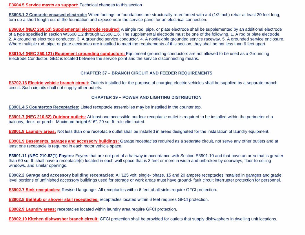
E3604.5 Service masts as support: Technical changes to this section. E3608.1.2 Concrete encased electrode: When footings or foundations are structurally re-enforced with # 4 (1/2 inch) rebar at least 20 feet long, turn up a short length out of the foundation and expose near the service panel for an electrical connection. E3608.4 (NEC 250.53) Supplemental electrode required: A single rod, pipe, or plate electrode shall be supplemented by an additional electrode of a type specified in section W3608.1.2 through E3608.1.6. The supplemental electrode must be one of the following. 1. A rod or plate electrode. 2. A grounding electrode conductor. 3. A grounded service conductor. 4. A nonflexible grounded service raceway. 5. A grounded service enclosure. Where multiple rod, pipe, or plate electrodes are installed to meet the requirements of this section, they shall be not less than 6 feet apart. E3610.4 (NEC 250.121) Equipment grounding conductors: Equipment grounding conductors are not allowed to be used as a Grounding Electrode Conductor. GEC is located between the service point and the service disconnecting means.
CHAPTER 37 – BRANCH CIRCUIT AND FEEDER REQUIREMENTS E3702.13 Electric vehicle branch circuit: Outlets installed for the purpose of charging electric vehicles shall be supplied by a separate branch circuit. Such circuits shall not supply other outlets.
CHAPTER 39 – POWER AND LIGHTING DISTRIBUTION E3901.4.5 Countertop Receptacles: Listed receptacle assemblies may be installed in the counter top. E3901.7 (NEC 210.52) Outdoor outlets: At least one accessible outdoor receptacle outlet is required to be installed within the perimeter of a balcony, deck, or porch. Maximum height 6’-6”. 20 sq. ft. rule eliminated. E3901.8 Laundry areas: Not less than one receptacle outlet shall be installed in areas designated for the installation of laundry equipment. E3901.9 Basements, garages and accessory buildings: Garage receptacles required as a separate circuit, not serve any other outlets and at least one receptacle is required in each motor vehicle space. E3901.11 (NEC 210.52(1) Foyers: Foyers that are not part of a hallway in accordance with Section E3901.10 and that have an area that is greater than 60 sq. ft. shall have a receptacle(s) located in each wall space that is 3 feet or more in width and unbroken by doorways, floor-to-ceiling windows, and similar openings. E3902.2 Garage and accessory building receptacles: All 125 volt, single- phase, 15 and 20 ampere receptacles installed in garages and grade level portions of unfinished accessory buildings used for storage or work areas must have ground- fault circuit interrupter protection for personnel. E3902.7 Sink receptacles: Revised language- All receptacles within 6 feet of all sinks require GFCI protection. E3902.8 Bathtub or shower stall receptacles: receptacles located within 6 feet requires GFCI protection. E3902.9 Laundry areas: receptacles located within laundry area require GFCI protection. E3902.10 Kitchen dishwasher branch circuit: GFCI protection shall be provided for outlets that supply dishwashers in dwelling unit locations.

E3902.16 Arc-fault protection of bedrooms outlets: Branch circuits that supply 120-volt, single phase, 15 ampere and 20 ampere outlets installed in bedrooms shall be protected by any of the following: 1) A listed combination-type arc fault circuit interrupter installed to provide protection of the entire branch circuit. 2) A listed branch/feeder-type-AFCI installed at the origin of the branch-circuit in combination with a listed outlet branch-circuit type arc-fault circuit interrupter installed at the first outlet box on the branch circuit. The first outlet box in the branch circuit shall be marked to indicate that it is the first outlet of the circuit. 3) A listed supplemental arc protection circuit breaker installed at the origin of the branch circuit in combination with a listed branch-circuit type arc-fault circuit interrupter installed at the first outlet box on the branch circuit where all of the following conditions are met: 3.1 The branch-circuit wiring shall be continuous from the branch circuit overcurrent device to the outlet branch-circuit arc-fault interrupter. 3.2 The maximum length of the branch-circuit wiring from the branch-circuit overcurrent device to the first outlet shall not exceed 50 feet for 14AWG conductors and 70 feet for 12 AWG conductors. 3.3 The first outlet box on the branch circuit shall be marked to indicate that it is the first outlet on the circuit. 4) A listed outlet branch-circuit type arc-fault circuit interrupter installed at the first outlet on the branch circuit in combination with a listed branch-circuit overcurrent protection device where all of the following conditions are met: 4.1 The branch-circuit wiring shall be continuous from the branch-circuit overcurrent device to the outlet branch circuit are-fault circuit interrupter. 4.2 The maximum length of the branch-circuit wiring for the branch-circuit overcurrent device to the first outlet shall not exceed 50 feet and for 14 AWG conductors and 70 feet for 12 AWG conductors. 4.3 The first outlet box on the branch circuit shall be marked to indicate that it is the first outlet on the circuit. 4.4 The combination of the branch-circuit overcurrent device and outlet branch-circuit AFCI shall be identified as meeting the requirements for a system combination-type AFCI and shall be listed as such. 5) Where metal outlet boxes and junction boxes and RMC, IMC, EMT, Type MC or steel-armored Type AC cables meeting the requirement of Section E3908.8, metal wireways or metal auxiliary gutters are installed for the portion of the branch-circuit between the listed branch-circuit overcurrent device and the first outlet shall be considered as providing protection for the remaining portion of the branch circuit. 6) Where a listed metal or nonmetallic conduit or tubing or Type MC cable is encased in not less than 2 inches of concrete for the portion of the branch circuit between the branch-circuit overcurrent device and the first outlet branch–circuit type SFCI installed at the first outlet shall be considered as providing protection for the remaining portion of the branch circuit. Exception: AFCI protection is not required for an individual branch circuit supplying only a fire alarm system where the branch circuit is wired with metal outlet and junction boxes and RMC, IMC, EMT or steel sheathed armored cable type AC, or MC meeting the requirements of Section E3908.8.
CHAPTER 39 – DEVICES AND LUMINARIES E4001.15 Switches controlling lighting loads: New list with seven scenarios that do not require a neutral conductor. E4002.9 Fifteen and 20-ampere receptacles in wet locations: now require “extra duty hoods”. Deleted wording “where supported from grade”. E4002.15 Dimmer-controlled receptacles: DC controlled receptacles are prohibited unless the plug/receptacle combination is a non-standard type listed for such use.

E4003.12 (NEC 410.16) Clothes Closet Luminaires: LED lighting may be installed in a closet, must follow the rules for spacing as incandescent lighting.
NEC REQUIREMENTS
NEC 680.43 EX #2 Indoor Spas and Hot Tubs: New exception for indoor spas and hot tubs on finished floors, equipotential bonding not required. NEC 680.21(c) GFCI Motor Protection: 120 volt through 240 volt outlets supplying pool pump motors must be GCFI protection for permanent installations. NEC 680.43 EX #2 Indoor Spas and Hot Tubs: New exception for indoor spas and hot tubs on finished floors, equipotential bonding not required.
CHAPTER 42 – SWIMMING POOLS (IRC) AND INTERNATIONAL SWIMMING POOL AND SPA CODE
E4203.4.3 – Low-voltage luminaires: Listed low voltage luminaires not requiring grounding, not exceeding low voltage contact limit, and supplied by listed transformers or power supplies that comply with Section E4206.1 shall be permitted to be located less than 5 feet from the inside wall of the pool. E4204 Bonding: See revisions to Sections E4204.2 (2) exceptions and E4204.3 for pool water. NEC 680.21(c) GFCI Motor Protection: all pool pump motors shall provide GCFI protection. ISPSC Chapter 3 - General Compliance: See all of chapter 3 for various revisions. ISPSC Chapter 7 - Onground Storable Residential Swimming Pools: See all of chapter 7 for various revisions. ISPSC Chapter 8 – Permanent Inground Residential Swimming Pools: See all of chapter 8 for various revisions.
FLOOD ZONE AND NOISE

ZONE REQUIREMENTS Flood Zone AE: In accordance with the Chesapeake Floodplain Management Ordinance, the lowest finished floor elevation of all new construction or substantial improvement of residential structures (including manufactured homes) must be a minimum of 1.5 feet (18 inches) above the base flood elevation (BFE) per the Flood Ordinance. This elevation is called the design flood elevation (DFE).
• All mechanical equipment, and electrical devices must be elevated to or above the (DFE). • HVAC ducts may be below the DFE but must be elevated above the base food elevation (BFE). • All mechanical equipment stands must be elevated to the DFE and be anchored to resist flotation. Equipment located on the exterior of the
structure, must be anchored to the stand to resist both wind and flood loads. The stand must be made of flood resistant materials per ASCE-24. • Flood vents are required on all homes located in a flood zone, regardless of the elevation of the enclosed area. Flood openings must be installed
on at least two different exterior wall sides of each enclosed area, such as crawl spaces, attached garage areas or lowest floor of a shed or similar utility building.
• Flood vents must be installed not more than twelve (12) inches above the highest adjacent grade on an exterior wall. • The crawl grade must be at or above the highest adjacent exterior grade. • All construction materials including wood studs, sheathing, insulation and drywall must not be installed below the BFE unless the material is
flood resistant as per ASCE-24, the IBC and IRC. Examples of flood resistant materials are pressure treated wood and cement board. For more details, see FEMA Technical Bulletin 2.
• Sheds, utility buildings and detached garages may be installed at grade in a flood hazard area but must be anchored to resist flotation and all materials below the BFE must be water-resistant.
A FEMA flood elevation certificate, prepared by a licensed surveyor, must be submitted and approved by this department before issuance of a certificate of occupancy. NOISE ZONES
Fentress Airfield Noise Zone area: Dwelling units constructed in the Fentress noise zone area, as determined by Chesapeake Zoning Ordinance, must submit a noise attenuation test, conducted by a registered design professional before a certificate of occupancy is issued. The test must indicate a noise level no greater than 45 Ldn over a 24 hour period of time.