r-448 - failure and repair of experimental continuously
TRANSCRIPT

-- ------ --------------
FAILURE AND REPAIR OF EXPERIMENTAL CONTINUOUSLY REINFORCED CONCRETE PAVEMENT
I 96: Portland Road to M 66
J. E. Simonsen
Research Laboratory Division Office of Testing and Research Research Project R-57 F-46 Research Report No. R-448
Michigan State Highway Department John C. Mackie, Commissioner
Lansing, March 1964

FAILURE AND REPAIR OF EXPERIMENTAL CONTINUOUSLY REINFORCED CONCRETE PAVEMENT
I 96: Portland Road toM 66
Synopsis
This report analyzes the causes of five failures--two in welded wire mesh sections, one in a bar mat section, and two in the conventional pavement section--in the continuously reinforced experimental pavement project on I 96 between Portland Road and M 66, as determined from observations before and during repair in 1963. A detailed description of repair procedures is included, satisfactory r:esults having been obtained using patch-at-a-time construction, night pouring of concrete, and, when necessary, expansion-joint relief sections.
Since the construction of Michigan's test road for study of continuously reinforced concrete pavement in 1958, ten distressed local areas of the experimental pavement have been examined to determine the character of failure, and all have undergone repair through replacement, using several methods of reconstruction. The project's original construction was described in Research Report R-314 (December 1959), entitled "An Experimental Continuously Reinforced Concrete Pavement in Michigan," which was reprinted in Highway Research Board Bulletin No. 274. The first five failures were discussed in Research Report R-397 (November 1962), and their repair in May 1962 was described in Research Report R-409 (January 1963). The causes and repairs of the second five failures are the subject of this report.
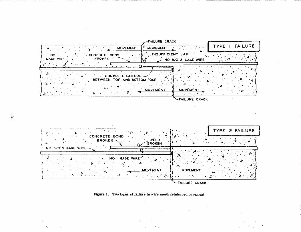
In the course of analyzing the first five· failures, it was determined that the distress in the welded wire reinforced sections could be described in two specific categories:
Type 1 failures are characterized by a vertical crack extending from the slab surface to the depth of the reinforcing steel, then by a horizontal crack or separation of the concrete between the steel mats to the end of the lower mat, where a vertical crack extends to the bottom of the slab. Because of an insufficient lap--the first crosswire in the upper mat being placed ahead of the last cross wire of the lower mat so that the longitudinal wires are not anchored--the bond resistance of the plain wire is broken and movement is possible a8 shown in Fig. 1. Poor consolidation of the two concrete layers facilitates the formation of the horizontal crack at the steel level.
I
"" I
,..--FAILURE CRACK I .-.-.. ---------,-.. -.• -.. -:-----M-O_V_E_M_E_N_T--,· MOVEMENT ·~··.,,.-:.' TYPE I FAILURE
NO 1 R
2 . u . CONCRETE BO~ . ·. · . · :
GAGE WIRE . . . . BROKEN ~ : · 1·/ INSUFFICIENT LAP .• ·· .. · · ... ·: ·. ·.:.· :· .. ·::: ·: 4 ·::·~ K' · · .,;.:-No. !:'>10' S GAGE WIRE · · · . O ... f· · · . ·: ·. · · .. ·. ·· j
1 . . . . '
: . p..
. ·~ .
. j,. : . ...
. . . ...
J>
NO. 5/0'S
. ...
. . . . . · .. co~c~E~E FA;L~RE _/ . ".
BETWEEN TOP AND BOTTOM POUR
. 4.
. 9
CONCRETE BOND
"'· .. BROKEN '\_ ·
b.· MOVEMENT
.• I> . . . ., . . · WELD . · . · ~BROKEN .. ·
GAGE WIRE--..,. .
4 NO. I GAGE WIRE.). . ·, .· ...
··~ .·.
.. • . . . ,l>.
.J>' .
• ,... ., • • ·J> •
I> MOVEMENT J> .
'-.FAILURE CRACK
.I TYPE 2 FAILURE
. A. ~ .... · ;.. .·. >4 :. ·. ::.~ .. ( ·. ·. 4 ..
FAILURE CRACK
Figure 1. Two types of failure in wire mesh reinforced pavement.

Type 2 failures are distinguished by a vertical crack extending the full depth of the slab through a section at the end of the reinforcing mat. The weld at the crosswire connection in the lap fails, as well as the bond to the longitudinal steel extending through the vertical failure crack. The slab is then free to move as shown in Fig. 1. Cores taken in the slab through failed crosswire connections have indicated the presence of moisture and various degrees of rusting of the reinforcement steel in the weld area, which undoubtedly increased the possibility of weld failure. Poor consolidation between the two concrete layers in the lap area apparently allows moisture to progress along this plane as water seeps down through the vertical crack. Although the initial cause of the weld failure is not known, it is believed that improper welding or rusting of welds caused some of the crosswire connections to fail before the maximum forces induced by shrinkage and temperature were developed. As a result, the stress normally taken by the failed welds is transferred to the remaining cross wire connections, causing an overstress and a progressive failure across the slab.
1962 Repairs
The areas reconstructed in 1962 were as follows:
Area No. Station Roadway Lane Reinforcement Type
1 1071+90 westbound traffic & passing welded wire mesh 2 1045+70 westbound traffic welded wire mesh 3 875+90 eastbound traffic & pas sing welded wire mesh 4 1017+03 eastbound traffic & passing bar mat 5 1044+66 eastbound traffic & passing bar mat
The three failures in the welded wire mesh sections occurred at laps in the reinforcement and were found to have been caused by either or both of the two basic types of failure.
The two failures in the bar mat sections occurred in morning pours, adjoining construction joints. These failures were analyzed as having been caused by poor consolidation of the concrete in these areas and by discontinuity in steel reinforcement resulting from the reinforcement having been placed in different horizontal planes at the lap following the construction joint.
-3-

1963 Repairs
In the regular quarterly inspection performed in February 1963, the following additional failures were encountered:
Area Station Roadway Lane Reinforcement Type No,
6* 1071+90 westbound traffic welded wire mesh 7 1045+40 westbound traffic & passing welded wire mesh 8 976+87 eastbound traffic & passing standard mesh 9 990+82 eastbound traffic & pas sing standard mesh
10* 1044+66 eastbound traffic bar mat
* The failures at Areas 6 and 10 occurred in traffic lane repair patches of May 1962,
The condition of these five failures is shown in Figs. 2 and 3. These five failures were recommended for repair in Research Report No. R-424 (May 1963), entitled "Repair of Continuously Reinforced Experimental Pavement: I 96, Portland Road to M 66." The areas proposed for replacement at each of the five locations and the probable causes of failure as determined from core investigations were discussed and recommended construction procedures were presented.
Causes of Failure
The following discussion pertains to causes of failure as determined from a core investigation prior to repair, supplemented by information obtained during removal of the distressed pavement areas:
Area 6 (Continuously Reinforced Pavement). The failure was confined to the traffic lane and occurred in the repair patch of May 1962. In the original repair, the replacement steel was welded to existing reinforcement in the traffic lane as required, but air temperature rose about 30 deg before concrete was ready for placement, causing both the traffic lane replacement steel and the badly deteriorated passing lane pavement to buckle. Since high temperatures prevailed at the time, the replacement steel was cut and spliced in the center of the traffic lane patch just before pouring of the concrete so as to maintain the reinforcement at the required horizontal level. A 30-deg drop in temperature within the first 24 hr after pouring apparently caused a bond failure which resulted in excessive slippage, and a large single crack formed near the center splice within a day after patching.
-4-

(wire mesh continuously reinforced pavement)
Figure 2. Condition of failures on westbound roadway (photos: July 1963).
Area No. 8 Area No. 9
(conventional reinforced pavement)
Area No. 7 (wire mesh continuously reinforced pavement)
Area No. 10 (bar mat continuously reinforced pavement)
Figure 3. Condition of failures on eastbound roadway (photos: July 196 3),
-5-

When the failed patch was removed, the welded splices , at the end limits of the patch, were found to have remained intact. However, examination of the tied center splices revealed that sliding had occurred at this point and thus it was verified that the failure was caused by insufficient bond development at the tied center splices.
Area No. 7 (Continuously Reinforced Pavement). The failure in the welded wire mesh at this location was determined to have occurred at a lap in the reinforcement, by taking test cores through the failure crack. A core taken through the crosswire location of the lap in the passing lane (Fig. 4A) indicated that a Type 2 failure had occurred. To find the exact cause of failure, existing reinforcement in the distressed area was exposed for inspection as shown in Fig. 4B. The lap was found to be as specified across the full width of the roadway (Fig. 4C). The failure was determined to have been caused by a combination of both failure types, and by rusting through of several longitudinal wires at the crack location. Fig. 5 shows a detailed sketch of the failure. As shown, the Type 1 failure was confined to the area at the traffic lane shoulder comprising 17 longitudinal wires. In the area classified as a Type 2 failure, 33 of the remaining 75 longitudinal wires had failed by rusting.
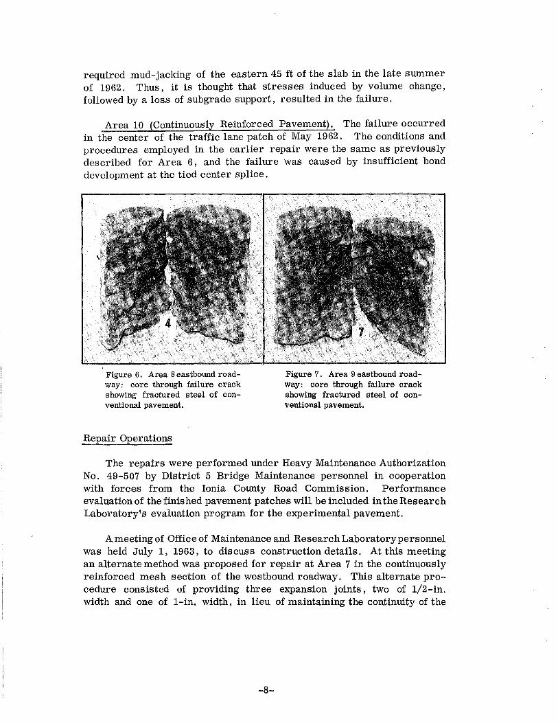
Area 8 (Conventional Reinforced Pavement). A core taken through the failure crack in the center of the passing lane (Fig. 6) indicated that the reinforcement had failed by rusting. It was verified during removal of the failed pavement that the reinforcement across the full width of the roadway had rusted through. The failure.crackwas located. approximately at the third-point of a 99-ft slab, and 20 ft east of a strain gage installation in the center of the slab, where a plane of weakness was formed by inserting a corrugated steel crack former during construction. The failure crack originated three months before formation of the crack at the intentionally formed plane of weakness. The failure crack occurred 4 ft west of a 15-in. culvert and extended through the sealed shoulders. Inasmuch as joint width measurements show that joints on either side of the failure are performing satisfactorily, it appears that loss of subgrade support rather than induced temperature and shrinkage stresses was responsible for the failure.
Area 9 (Conventional Reinforced Pavement). The reinforcement at this location had failed in both lanes by rusting, as shown by a core (Fig. 7) taken through the failure crack and by observations during removal operations. The failure occurred at the approximate midpoint of a slab of an unusual length--136 ft 9 in. The crack originated five months after construction of the pavement, and subsequent settlement of the subgrade
-·6-

I ..;J I
Figure 4. Repair excavation and core fromArea7wes1hound roadway. A: Core through section at crosswire, broken at steel level to show weld failure. B: Exposed reinforcement in traffic lane at failure location. C : Wire mesh reinforcement with specified lap.
Figure 5 (right). Exposed wire mesh reinforcement lap at failure: sta. 1045+ 40 westbound roadway (Area 7).
..... t:l z Ill) ::> a: )
m 0 UJ
Ul...J a:< 3_u. <(X u.= N~
PASSING
LANE
UJO D..UJ >-t-
I-l-<(- ---:---ct.---- ----z I
UJ a: ::>
-...J
< u. UJ D.. )-
1-
t
" iii UJ 0
II) UJ a: ~
LANE
PLAN VIEW
ELEVATION VIEW
required mud-jacking of the eastern 45 ft of the slab in the late summer of 1962. Thus, it is thought that stresses induced by volume change, followed by a loss of subgrade support, resulted in the failure.
Area 10 (Continuously Reinforced Pavement). The failure occurred in the center of the traffic lane patch of May 1962. The conditions and procedures employed in the earlier repair were the same as previously described for Area 6, and the failure was caused by insufficient bond development at the tied center splice.
Figure 6. Area 8eastbound roadway: core through failure crack showing fractured steel of conventional pavement.
Repair Operations
Figure 7. Area 9 eastbound roadway: core through failure crack showing fractured steel of conventional pavement.
The repairs were performed under Heavy Maintenance Authorization No. 49-507 by District 5 Bridge Maintenance personnel in cooperation with forces from the Ionia County Road Commission. Performance evaluation of the finished pavement patches will be included in the Research Laboratory's evaluation program for the experimental pavement.
A meeting of Office of Maintenance and Research Laboratory personnel was held July 1, 1963, to discuss construction details. At this meeting an alternate method was proposed for repair at Area 7 in the continuously reinforced mesh section of the westbound roadway. This alternate procedure consisted of providing three expansion joints, two of 1/2-in. width and one of l-in. width, in lieu of maintaining the continuity of the
-8-

reinforcement through the area as originally recommended in Research Report No. R-424. Because the expansion joint method appeared expedient and. economical, as compared to maintaining the reinforcement continuity by welding, it was the consensus that this method should be used.
The repair operations began September 23, 1963, and were completed October 3, 1963. The dimensions of each of the five repair areas are shown in Figs. 8 through 12. Lane-at-a-time and patch-at-a-time construction was employed at the three failure locations in the continuously reinforced sections. Failed pavement at each failure location was removed and replaced in a continuous operation sequence for the single lane. All patches in these sections were replaced within 18 hr after removal began. The two patches in the conventional pavement section were repaired during normal working hours, using single-lane construction.
Removal Operations
Before removing the distressed pavement, a 1-1/2-in. deep sawcut was made across the full width of each patch at its end limits. At the point where the reinforcement was to be cut, a trench was made across the slab with pneumatic hammers, to expose the steel for cutting by acetylene torch. Once the center portion of the patch was separated from the main slab, it was broken using a mobile crane with a demolition ball, and removed by a front-end loader and hand tools. In the end portions of the repair areas the concrete was removed with pneumatic hammers and hand tools, to ensure that the existing reinforcement remained straight, and to minimize the degree of undercutting of the vertical end faces of the patches.
The removal sequence of concrete and steel, illustrated in Figs. 13 through 17 , was as follows:
1. Sawing 1-1/2 in. deep sawcut at the designated locations.
2. Breaking and removing concrete to expose reinforcement at the ends of the area where both concrete and steel were to be removed.
3. Cutting the existing reinforcement at the required distance from the end limits of the patch.
4. Breaking and removing the concrete and steel in the center of the patch.
5. Breaking and removing only the concrete at the two end regions of the patch, while leaving existing reinforcement intact.
-9-

~- · CONC. ONLY --REMOVED FROM THESE AREAS
LIMITS Of" OLD PATCH
..... =>"' u~ 3:., <(,
"'-
TRAFFIC LANE
PASSING LANE
Figure 8. Repair limits of Area 6 (Sta. 1071+90): wll"e mesh continuously reinforced pavement.
~ ~ .. ..... "' =>"' "' u~
~ 0
=£: PASSING ::· LANE <(~
"'= " ~ ~ >-::>
u TRAFFIC CDNCETE ONLY REMOVED FROM THESE A?ffl!l/ :::-.:_ :: LANE
<( <I)
25' 1'-e~'r Figure 9. Repair limits of Area 7 {Sta. 1045+40): wire. mesh continuously reinforced pavement.
~ ~ '"""' ""'' CONC. ~ STEEL , '-... "-..: REMOVED ~
FR~~~
.. "' "' 0
=N :;,
.... ::> u
~ "'
PASSING LANE
TRAFFIC LANE
Figure 10. Repair limits of Area 8 (Sta. 976+87): conventional reinforced pavement.
-10-

.. ~ ~····' .. "' ~ CONC. 6. STEEL ' "' ...
REMOVED "' Q
~HIS~ 0 PASSING LANE
·~ :N
"
... ~'\';;~.~~~ ... ::> :> u ~VEDFRO u
SE AREAS TRAFFIC LANE
! :;:: <( (/)
~~·-e•• 21-611 1'-e•_.j
Figure 11. Repair limits of Area 9 (Sta. 990+82): conventional reinforced pavement.
41-9'4
CONC. ONLY REMOVED FROM THESE AREAS
l- LIMITS OF OLD PATCH ------1 I
.. ....... ""' uo 'l:'i-1
"" "'-
TRAFFIC LANE
PASSING LANE
Figure 12. Repair limits of Area 10 (Sta. 1044+66): bar mat continuously reinforced pavement.
-11-

I ..... t>:) I
Figure 13. Sawing 1-1/2-in. deep sawcut with diamond saw.
Figure 14. Cutting steel with acetylene torch.
Figure 15. Breaking center portion of patch with crane and ball.
Figure 16 (left). Removing concrete with front end loader.
Figure 17 (right). Cleaning vertical end face.

Replacement Operations
At all repair patches, low areas in the subbase surface resulting from removal of the concrete Were backfilled with sand and compacted to specified density with a pneumatic compactor. The reinforcement types,, load transfer assemblies, and their placement in the various repair areas were as follows:
Area 6 (Continuously Reinforced Pavement). Continuity of the reinforcement was maintained by a 3-ft splice at the end limits of the patch rather than by welding. Performance of the 1962 repairs had shown that the reinforcement continuity can' be re-established by splicing the steel, provided the failure is confined to only one lane. The longitudinal reinforcement consisted of No. 4 deformed bars conforming to the requirements for hard grade steel ASTM Designation A-432. The existing spacing of the longitudinal steel was maintained by placing the replacement bars adjacent to each existing wire. The transverse bars were spaced at 2 ft 3 in. centers and consisted of No. 3 deformed bars meeting the specifications for intermediate grade steel ASTM Designation A-15. The reinforcement was suspended at the required level from 2- by 4-in. timbers spanning the patch (Fig. 18).
Area 7 (Continuously Reinforced Pavement). Rather than re-establish the continuity through this area, a relief section of three, expansion joints was constructed. The replacement steel consisted of conventional reinforcement mats, and approved expansion joint load transfer assemblies were installed at the spacing shown in Fig. 19. As shown, 1/2-in. wide fillers were used in the two end joints whereas the filler in the center joint was l-in. wide. The joint grooves over the 1/2-in. joints were formed by use of a plastic U-shaped cap. This plastic cap was placed on the filler prior to pouring concrete (Fig. 20), and after initial finishing of the concrete the cap was raised manually to the surface and the joint finished by hand trowelling. The joint groove over the l-in. expansion joint was formed by means of a 1- by 3/4-in. wood strip. Both the plastic cap and the wood strip were left in place for protection of the joints until sealing.
Areas 8 and 9 (Conventional Reinforced Pavement). A contraction joint load transfer assembly was placed in the center of each patch and the replacement steel consisted of standard reinforcement, which was lapped approximately 18 in. with the existing reinforcement at the ends of the patches and extended to within 3 in. of the joint centerline. The condition of a typical repair area ready for concrete pour is shown in Fig. 21. Styrofoam was used to form a 1/2- by 2-in. joint groove.
-13-

OF OLD PATCH
Figure 20 (below). 1/2-in. expansion joint load transfer assembly with plastic cap in place at Area 7.
-14-
Figure 18 (left). Steel arrangement on Area 6.
Figure 19 (below). Spacing of expansion joints in patch at Area 7.
EXISTING

Area 10 (Continuously Reinforced Pavement). As in the case of Area 6. the reinforcement continuity was maintained by a 3-ft lap at the end limits of the patch. The longitudinal steel consisted of No. 5 deformed bars meeting the requirements· for hard grade steel ASTM Designation A-432. The transverse steel was No. 3 deformed bars conforming to the specifications for intermediate grade steel ASTM Designation A-15. The longitudinal bars were placed adjacent to each existing bar, while the transverse bars were spaced at 2 ft 3 in. centers. Individual chairs were used to support the reinforcement at the required level. Fig. 22 shows the steel arrangement for this area.
The concrete consisted of a high-early-strength transit mix with a constant cement content of 7. 5 sacks of Type 1A cement per cu yd. The average air content of the mix, provided by addition of either Toximent or Dar ex AEA, was 5. 4 percent and the average slump was 3 in. At each lane patch in the continuously reinforced sections (Areas 6, 7, and 10), three 6-in. diam test cylinders were molded and one specimen from each patch was tested in compression at 1/2, 3, and 7 days. The average compressive strengths at these respective ages were 325, 2450, and 3000 psi.
The concrete in Areas 6, 7, and 10 was poured during the early evening hours of the same day that the distressed pavement was removed. This was done to minimize the amount of temperature drop while the concrete was setting, and to provide time for development of strength to resist the compressive stress induced by the ensuing temperature rise of the following day. The remaining two patches, Areas 8 and 9, were poured during regular working hours as soon as the removal operations were completed.
Date, time, and temperature data during concreting operations at each of the five locations are shown in Table 1. In addition, temperature variations for the first 24 hours after pouring of Areas 6, 7 , and 10 are shown in this table. As indicated, the critical temperature drop during initial curing of these three patches varied from only 2 to 6 deg F, and field temperature charts show that the lowest recorded air temperature at each of the three locations occurred about 8 hr after pouring.
The joints in Areas 7, 8, and 9 were cleaned by sandblasting prior to sealing with hot-poured rubber-asphalt type compound. The sealer was melted in a thermostatically controlled kettle of the double-boiler type and applied to the joint through a pressure pump with hose and nozzle.
-15-

TABLE 1 TEMPERATURE VARIATION DURING CONCRETE PLACEMENT
Pour 24-hr Pour Area
Lane Station Roadway Pour
Temp, Temperature Variation, deg F* Date No. Time
deg F I I High Mean Low
9-23-63 6 Traffic 1071+90 WB 9:30PM 42 70 52 37
9-24-63 7 Traffic 1045+40 WB 9:30PM 54 82 60 48
I 9-24-63 .. 10 Traffic 1044+66 EB 9:30PM 54 80 61 49
"' I 9-27-63 8 Traffic 976+87 EB 1:30PM 76
9-27-63 9 Traffic 990+82 EB 2:00PM 76
9-30-63 7 Passing 1045+40 WB ·8:30PM 46 80 56 44
10-1-63 8 Passing 976+87 EB 4:30PM 70
10-1-63 9 Passing 990+82 EB 5:00PM 67
* Based on first 24-hr period after concrete pour.

The replacement sequence, shown in Figs. 23 through 30, was as follows:
1. Compacting subbase, setting forms, placing steel, and in the case of Areas 7, 8, and 9, placing load transfer assemblies.
2. Delivering and spreading concrete.
3. Vibrating concrete with pneumatic vibrator.
4. Striking off concrete with screed.
5. Forming joint grooves (Areas 7, 8, and 9 only).
6. Final hand finishing of concrete surface.
7. Applying burlap drag finish to concrete surface.
8. Applying membrane curing compound.
9. Cleaning and sealing of joints (Areas 7, 8, and 9 only).
Plugs for Joint Width Measurement
In order to determine the magnitude of movement of the three expansion joints installed in the patch at Sta 1045+40 westbound roadway (Area 7), a set of gage plugs was placed at each joint, 12 in. from the pavement edge in the traffic lane and 4 in. each side of the joint centerline. The plugs were placed just before burlap drag finishing and the initial reading was taken as soon as the plugs were firmly embedded. Subsequent measurements will be taken at the same regularly scheduled quarterly intervals at which the joint width readings are taken for the original instrumented joints.
Concluding Remarks
Such precautions as patch-at-a-time construction and night pouring of concrete to minimize temperature effects, appear to be justifiable requirements when repairing continuously reinforced pavement. Only ordinary crack patterns have developed in the patches where continuity was re-established using these methods. The expansion joint method of repair seems promising where drastic reduction in reinforcement stress may be provided by a relief section of this type, particularly where the pavement adjoining the failure exhibits clear evidence of probable future failure (as was the case in Area 7). Final conclusions regarding the merits of this type of repair may be drawn when conclusive data have been obtained.
-17-

Figure 23 (top left). Delivering and spreading concrete.
Figure 24 (top right). . Vibrating concrete with pnel,Ullatic vibrator.
Figure 25 (bottom left). Initial finishing of concrete with screed.
Figure 26 (bottom right). Final hand finishing of concrete surface.
-18-

Figure 27 (top left). Applying burlap drag finish.
Figure 28 (top right). Applying me:ml>rane curing compound.
Figure 29 (bottom left). Cleaning joint by sand blasting.
Figure 30 (bottom right). Sealing joint with hot-poured rubber-asphalt.
-19-