quick start - transcat · 2015-04-23 · quick start general inspection 1. inspect the shipping...
TRANSCRIPT

Quick Start
SHS1000 Series Handheld Digital Oscilloscope
QS03010-E02A
2015 SIGLENT TECHNOLOGIES CO., LTD


SHS1000 快速指南 I
Guaranty and Declaration
Copyright
SIGLENT TECHNOLOGIES CO., LTD. All Rights Reserved.
Trademark Information
SIGLENT is the registered trademark of SIGLENT TECHNOLOGIES CO., LTD
Declaration
SIGLENT products are protected by patent law in and outside of
P.R.C.
SIGLENT reserves the right to modify or change parts of or all the
specifications or pricing policies at company’s sole decision.
Information in this publication replaces all previously corresponding
material.
Any way of copying, extracting or translating the contents of this
manual is not allowed without the permission of SIGLENT.
SIGLENT will not be responsible for losses caused by either
incidental or consequential in connection with the furnishing, use or
performance of this manual as well as any information contained.
Product Certification
SIGLENT guarantees this product conforms to the national and industrial standards in china as well as the ISO9001: 2008 standard and the ISO14001: 2004 standard. Other international standard conformance certification is in progress.

II SHS1000 快速指南
General Safety Summary
Carefully read the following safety precautions to avoid personal injury and prevent damage to the instrument or any products connected to it. To avoid potential hazards, please use the instrument as specified. Only qualified technician should perform service procedures Use Proper Power Line Use only the special power line of the instrument that approved by local state.
Ground the Instrument
The instrument grounds through the protective terra conductor of the power line. To avoid electric shock, the ground conductor must be connected to the earth. Make sure the instrument is grounded correctly before connect its input or output terminals.
Connect the Signal Wire correctly
The potential of the signal wire is equal to the earth, so do not connect the signal wire to a high voltage. Do not touch the exposed contacts or components.
Look Over All Terminals’ Ratings
To avoid fire or electric shock, please look over all ratings and sign instruction of the instrument. Before connecting the instrument, please read the manual carefully to gain more information about the ratings.
Not Operate with Suspected Failures
If you suspect that there is a damage of the instrument, please let a qualified service personnel check it.

SHS1000 快速指南 III
Avoid Circuit or Components Exposed
Do not touch exposed contacts or components when the power is on Do not Operate in Wet/Damp Conditions Do not Operate in an Explosive Atmosphere Keep the Surface of the Instrument Clean and Dry
Safety Terms and Symbols
Terms on the product. These terms may appear on the product:
DANGER: Indicates direct injuries or hazards that may happen.
WARNING: Indicates potential injuries or hazards that may happen. CAUTION: Indicates potential damages to the instrument or other property that may happen.
Symbols on the product. These symbols may appear on the product:
Hazardous Protective Warning Earth Ground Power
Voltage Earth Ground Switch

IV SHS1000 快速指南
General Care and Cleaning
Care:
Do not store or leave the instrument in direct sunshine for long periods of time.
Notice:
To avoid damages to the instrument or probe, please do not leave them in fog, liquid, or solvent.
Cleaning:
Please perform the following steps to clean the instrument and probe regularly according to its operating conditions.
1. Disconnect the instrument from all power sources, and then clean it with a soft wet cloth.
2. Clean the loose dust on the outside of the instrument and probe with a soft cloth. When cleaning the LCD, take care to avoid scarifying it.
Notice:
To avoid damages to the surface of the instrument and probe, please do not use any corrosive liquid or chemical cleanser.
Make sure that the instrument is completely dry before restarting it to avoid short circuits or personal injuries.

SHS1000 快速指南 V
Installation of Battery
The instrument is not installed with battery. To complete the installation, please operate as the following steps:
1. Remove the two screws on the battery cover using a screwdriver. As shown in figure 1.
2. Pull out the supporting leg and remove the battery cover. As shown in figure 2.
3. Put battery into the battery box and cover it tightly. As shown in figure3.
4. Tighten the screws using a screwdriver and turn on the instrument to check if it’s successfully installed.
Notices: Connect the battery cable lightly due to its anti-reverse design. If the instrument fails to startup after successful installation of
the battery, it is likely due to exhausting of the battery power, please charge the battery timely.
Figure 1 Figure 2
Figure 3

VI SHS1000 快速指南
Contents Guaranty and Declaration ................................................................................. I General Safety Summary ................................................................................. II Safety Terms and Symbols ............................................................................. III General Care and Cleaning ........................................................................... IV Installation of Battery....................................................................................... V Quick Start ....................................................................................................... 1
General Inspection .................................................................................... 1 Appearance and Size................................................................................ 2 Preparation for Use ................................................................................... 3
Adjusting the Supporting Leg ............................................................. 3 Measurement Connection .................................................................. 4 Power-on Inspection .......................................................................... 6 Function Inspection............................................................................ 7 Probe Compensation ......................................................................... 8
Front Panel Introduction............................................................................ 9 Side Panel Introduction ........................................................................... 11
Oscilloscope Function Summary .................................................................... 12 User Interface ......................................................................................... 12 Function Introduction .............................................................................. 16
Function Menu ................................................................................. 16 Trigger setting .................................................................................. 17 System setting ................................................................................. 17 Storage setting ................................................................................. 17 Cursor measurement ....................................................................... 17 Run setting ...................................................................................... 17 Auto setting ...................................................................................... 18 Menu setting .................................................................................... 18
Multimeter Function Summary ....................................................................... 19 User Interface ......................................................................................... 19 Measurement Parameters ...................................................................... 21
Recorder Function Summary ......................................................................... 22 Scope Trend Plot .................................................................................... 22 Scope Recorder ...................................................................................... 24 Meter Trend Plot ..................................................................................... 26
Troubleshooting ............................................................................................. 28 Contact SIGLENT .......................................................................................... 31

SHS1000 快速指南 1
Quick Start
General Inspection
1. Inspect the shipping container. Keep the damaged shipping container or cushioning material until the contents of the shipment have been completely checked and the instrument has passed both electrical and mechanical tests. The consigner or carrier will be responsible for damages to the instrument resulting from shipment. SIGLENT would not provide free maintenance or replacement.
2. Inspect the instrument. If there are instruments found damaged, defective or failure in electrical and mechanical tests, please contact SIGLENT.
3. Check the accessories. Please check the accessories according to the packing list. If the accessories are incomplete or damaged, please contact your SIGLENT sales representative.
2 SHS1000 快速指南
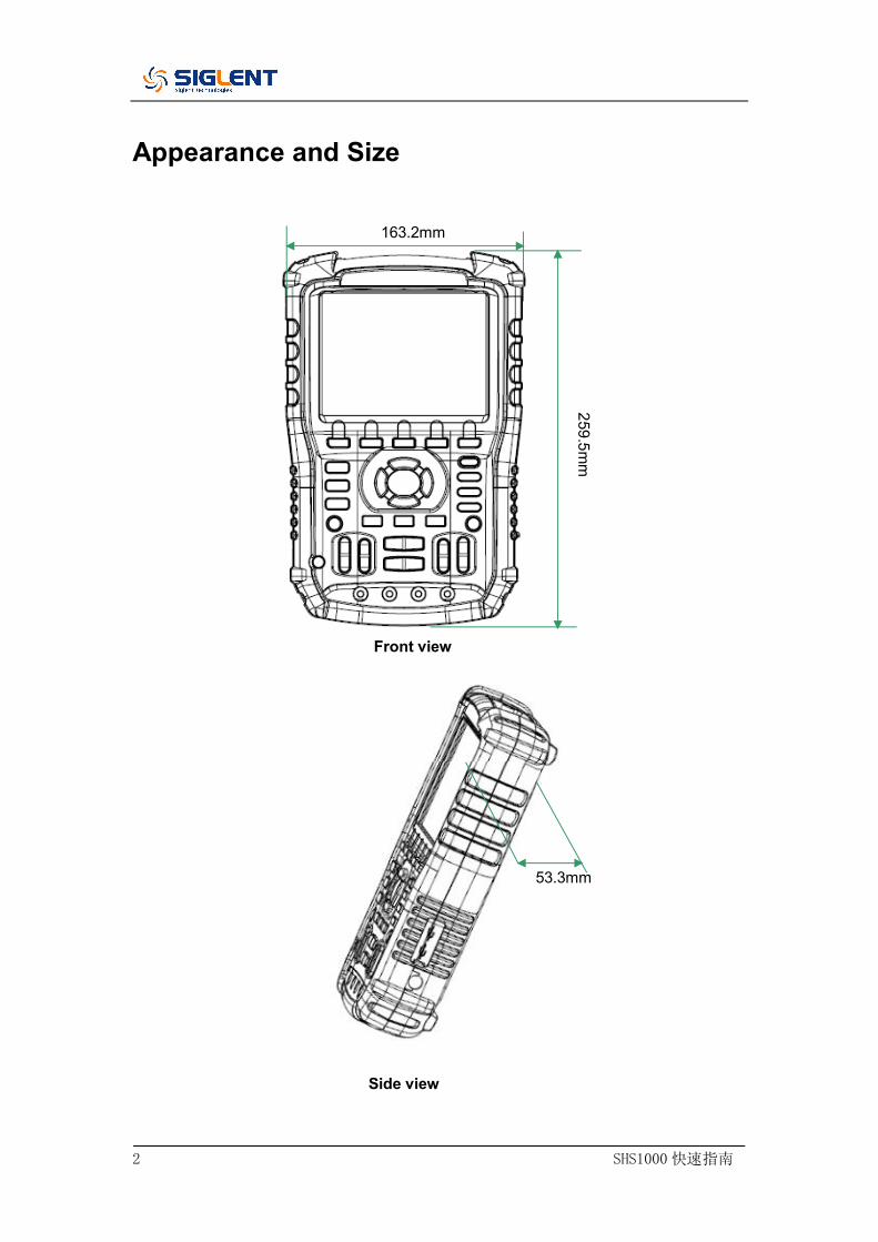
Appearance and Size 163.2mm
Front view
53.3mm
Side view
259.5mm

SHS1000 快速指南 3
Preparation for Use
Adjusting the Supporting Leg
Adjust the supporting leg properly to use them as stands to tilt the instrument upwards for stable placement as well as easier operation and observation of the instrument.
Adjust the supporting leg

4 SHS1000 快速指南
Measurement Connection
Accessories of SHS1000 Handheld Digital Oscilloscope consist of a power supply adapter, a probe adapter plug, a USB cable, two multimeter probes and two oscilloscope probes. The acceptable AC power supply is: 100~240V, 45~440Hz.
1. Oscilloscope Probe Connect the BNC end of the probe to the instrument BNC connector firstly, then connect the grounding alligator clip and probe of another end to the grounding end and signal compensation terminal of the probe adapter plug, which is connected to the BNC port of the instrument, for square waveform checking.
1
2
3

SHS1000 快速指南 5
2. Power Adapter Connect one end of the power adapter to power socket of the instrument and another end to AC power for charging.
3. Multimeter Pens Before connecting the multimeter pens, please select a measurement parameter firstly, and then plug respectively the red and black pen to corresponding connector according to the graphic cues displayed on the screen.

6 SHS1000 快速指南
Power-on Inspection
When the handheld oscilloscope is energized, press the power button on the front panel to boot up the scope. During the start-up progress, the instrument performs a series of self-test items and you could hear the sound of relay switching. After the self-test completed, the welcome interface displays immediately.

SHS1000 快速指南 7
Function Inspection
To check if the oscilloscope function system of the instrument works normally, please perform the following function inspection steps:
1. Press the Power button to turn on the instrument and it switches to scope function automatically after the power-on self test.
2. Connect the probe adapter plug to the USB port of the instrument.
3. Connect the BNC end of the probe to the BNC connector the instrument.
4. Connect the alligator clip and probe of another end respectively to the grounding end and compensation signal output terminal of the adapter plug.
5. Press AUTO to display square waveforms with 1KHz frequency and about 3V peak value in normal conditions as shown below:
6. Test channel 2 in the same method. If waveforms displayed do not like waveforms above, please perform the “Probe Compensation”.

8 SHS1000 快速指南
Probe Compensation
It is necessary to properly compensate the probe at first use of it. Non-compensated or inadequate compensated probe may cause inaccurate measurement. The following steps are about probe compensation:
1. Perform step 1, 2, 3 and 4 of “Function Inspection”. 2. Check the displayed waveforms and compare them with figure
below.
under compensated over compensated correctly compensated
3. Use a nonmetallic driver to adjust the low-frequency compensation adjustment hole on the probe until the waveforms change to be correct as the figure ”compensated correctly".

SHS1000 快速指南 9
Front Panel Introduction
1 2
3 4 5 6 7 8 9
12 11 10
20 19 18 17 16 15 14
13

10 SHS1000 快速指南
Number Instruction Number Instruction
1 LCD 11 Horizontal position/
Base scale control
2 Menu control keys 12 Trigger menu
3 Menu display key 13 Power key
4 Auto set 14 Channel 1 system
5 Trigger level zero key 15 User system
6 Run/Stop control 16 Recorder system
7 Cursor measurement 17 Multimeter system
8 Save/Recall system 18 Horizontal position
zero key
9 Vertical position/
Voltage scale control 19 Oscilloscope system
10 Multimeter inputs 20 Trigger level position

SHS1000 快速指南 11
Side Panel Introduction
1. USB Device This instrument can be connected to a printer for a print map of the current screen, or a PC for remote control via this port.
2. USB Host
Files including setup file, waveform file, BMP file and CSV file can be saved to removable storage device via this port.
3. Power Supply Socket
The instrument can be connected to AC power supply via this port. The acceptable AC power supply is: 100 ~240V,50/60HZ.
1 2 3

12 SHS1000 快速指南
Oscilloscope Function Summary
The default system of the instrument is oscilloscope function system on startup, or you could press to switch to oscilloscope function system. The User interface of the oscilloscope function system is shown below.
User Interface
1. Logo Siglent is the registered trademark of SIGLENT
TECHNOLOGIES., LTD. 2. Working State
Available working states of the instrument are: Ready, Auto,
Trig’d, Scan and Stop.
1 2 3 4 5 6 7
8
9
10
11
12
16 15 14 13
17
Scope

SHS1000 快速指南 13
3. Waveform Memory
Display position of the current waveforms in the oscilloscope memory.
Waveforms displayed on the screen
4. Trigger Position
Display trigger position of waveforms both in the memory and on the screen.
5. Print
Display the current option of “Print Key” under the “Print Setup” menu. P: “Print Key” option set to “Print Picture”; S: “Print Key” option set to “Save Picture”.
6. USB Device
Display the current option of “USB Device”.
“USB Device” option set to “Computer”;
“USB Device” option set to “Printer”. 7. State of Charge
Display the state of charge of the handheld oscilloscope.
Mark indicates the battery is full;
Mark indicates the battery is charging. The mark switching constantly between the two icons indicates the instrument has not been installed battery.
8. Time
Display correct time of the current operation.

14 SHS1000 快速指南
9. Trigger Level Display the vertical position of the trigger level.
10. Trigger Position
Display the horizontal trigger position of current waveforms. Use horizontal displacement control key to modify the parameter. Press right/left arrow key to make the arrowhead move right/left and the trigger displacement decreases/increases. By pressing the horizontal displacement zero key, you can quickly reset the parameter to zero as well as make the arrowhead return to center of the screen.
11. Frequency
Display frequency of the current waveforms. Set the Counter to “On” under the “User” menu to make the frequency displayed, or nothing will display.
12. Trigger Setting Trigger Level. Display vertical position of the current trigger
level, for example: 。 Trigger Type. Display the current trigger type and trigger
condition. Different trigger type has different mark, for example: means triggered on Slop side in edge trigger.
13. Horizontal Time Base
Represent time of each grid on the horizontal axis of the screen. Use the time base control key to modify the parameter, which is adjustable from 1nS to 50S.
14. BW limit
If the current “BW Limit” is “On”, then the mark displayed at
SHS1000 快速指南 15
the lower left corner of the screen, or nothing displayed. When the vertical scale changes to 2mV/div, the “BW Limit” is automatically turned on.
15. Voltage Scale
Represent the voltage value of each grid on the vertical axis of the screen. Use the voltage scale control key to modify the parameter, which is adjustable from 2mV to 5V.
16. Coupling Mode
Display coupling mode of the current waveforms. Available coupling modes are DC, AC and GND, each of them has unique mark displayed on the screen.
17. Current Channel
Display the current channel waveforms. Two channels can display at the same time.

16 SHS1000 快速指南
Function Introduction
Function Menu
Press the key to enter oscilloscope function system, as shown below:
Acquire Press the corresponding menu key to enter Acquire system, under which there are three selectable waveform acquisition modes: Sampling, Peak Detect and Average. Display Press the corresponding menu key to enter Display system, under which functions like display type, persist time, wave intensity and brightness are easy to set. Math Press the corresponding menu key to enter Math system, under which “+”, “-”, “×”, “÷” operations are available. Horizon Press the corresponding menu key to enter Horizon system, under which the delayed scan can be turned on or off. Reference Press the corresponding menu key to enter waveform reference system, under which the current waveforms can be compared with waveforms saved previously to help determine circuit failure.
Scope

SHS1000 快速指南 17
Trigger setting
Press the button to enter trigger system, under which five types of trigger including edge, pulse, video, slope and alternative are available, and each of them can be set in auto, normal or single mode.
System setting
Press the button to enter user system, under which the system status and auxiliary functionalities like buzzer, language and print setup are accessible to view or set. In addition, some advanced functions like self calibration, updating firmware and waveform recording are also supported.
Storage setting
按下 Press the button to enter Save/Recall system, under which four types of file including setups, waveforms, picture and CSV are accessible to save or recall, as well as recalling of the factory settings.
Cursor measurement
按下 Press the button to enter cursor measurement system, under which three measurement types including voltage, time and delay are selectable, and each parameter can be measured in manual, track or auto mode.
Run setting
Press the button to set the state of the instrument to “Run” or
“Stop”. In “Stop” state, the logo at the upper left corner of the screen turns red.
Trigger
Save Recall
Cursor
Run/Stop
User

18 SHS1000 快速指南
Auto setting
Press the button to enable the waveform auto setting function. The instrument will automatically adjust its horizontal time base, vertical scale and trigger mode according to the input signal to make the waveforms displayed in a perfect state.
Menu setting
Press the button to make the current menu displayed or disappeared on the screen.
Auto
Menu

SHS1000 快速指南 19
Multimeter Function Summary
User Interface
Press the button to enter multimeter function system, under which 8 types of parameters including DC voltage, AC voltage, resistor, diode, continuity, capacitance, DC current and AC current are selectable to measure.
Multimeter Interface
1. Relative Value To save a relative value, please firstly touch positive probe and negative probe of the multimeter directly to create a short circuit, and then turn on the Relative until the displayed value gets stable. Diode and continuity are not designed with the relative function. (Notes: after saving a relative value of any parameter, it’s later measured value equals to the displayed value, and will not be affected by the previously saved value)
1 2 3
4
5
6
Meter

20 SHS1000 快速指南
2. Connection Diagram Displayed on the screen based on the parameter you select to show you correct connecting method.
3. DC/AC Mark If a DC parameter (DC voltage or DC current) is selected, the
mark “DC” displayed at the upper right corner of the screen; If a AC parameter (AC voltage or AC current) is selected, the mark “AC” displayed at the upper right corner of the screen.
4. Operation Mode The selectable operation type is Auto or Manual. Diode,
continuity and capacitance are not designed with the operation mode.
5. Measurement Range Range that suits to the current measured value. In auto mode,
the instrument will automatically select appropriate range based on the measured value; In manual mode, if the current measured value exceeds the current range, an alarm sounds will remind you to change to proper range.
6. Parameter Value The current measured value. Whether the Relative set to On or
Off, the actual measured value equals to the displayed value, and will not be affected by relative value saved previously.
SHS1000 快速指南 21
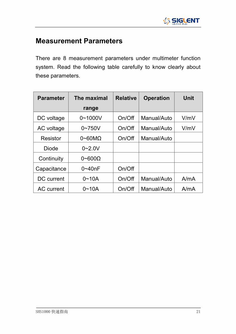
Measurement Parameters
There are 8 measurement parameters under multimeter function system. Read the following table carefully to know clearly about these parameters.
Parameter The maximal
range
Relative Operation Unit
DC voltage 0~1000V On/Off Manual/Auto V/mV
AC voltage 0~750V On/Off Manual/Auto V/mV
Resistor 0~60MΩ On/Off Manual/Auto
Diode 0~2.0V
Continuity 0~600Ω
Capacitance 0~40nF On/Off
DC current 0~10A On/Off Manual/Auto A/mA
AC current 0~10A On/Off Manual/Auto A/mA

22 SHS1000 快速指南
Recorder Function Summary
The recorder function of the instrument includes Scope Trend Plot, Scope Recorder and Meter Trend Plot. Here are description for Trend Plot and Scope Recorder: Trend Plot Curve of measured value change with time.
Observing the trend plot will make you a better prediction of change trend of the current parameter.
Recorder A continuous real-time recording of waveforms. All captured wave data will be saved and then played back. The maximal record length of the internal memory is 7Mpts.
Press the button to enter recorder function system:
Press any menu corresponding key to set the trend plot or recorder.
Scope Trend Plot
1 2 3
4
5
6
Recorder

SHS1000 快速指南 23
Press Recorder → Scope Trend Plot to enter the interface shown above, under which you could set the wanted parameter.
1. Record Time The time from the beginning of drawing the scope trend plot to now.
2. Data Percentage
The percentage of the recorded data occupied the total storage data.
3. Measured Value
The current measured value of channel 1 parameter.
4. Data/Time Reflect the relationship between the measured value and the
record time, which is defined as time of the intersection of the vertical scale and the scope trend curve.
5. Measurement Parameter Press the corresponding menu key to make the wanted
parameter trend curve. Three types of parameters including voltage, time and delay are accessible to select.
6. Vertical Scale
Value of the current selected parameter displayed at the vertical scale.

24 SHS1000 快速指南
Scope Recorder
Press Recorder → Scope Recorder to enter the interface shown below:
Under the menu of Option, you could set the Viewer, Record and Replay shown below.
Submenu Option Instruction
Viewer Split
Waveforms of channel1/2 displayed on
the upper/lower half screen.
Full Screen Waveforms displayed in full screen.
Record Continuous
Record data continuously, the current
data will be covered by later data if the
storage is full.
Single Recording stops if the storage is full.
Replay
By point When being replayed, the waveforms
are updated by points.
By frame When being replayed, the waveforms
are updated by a full screen of data.
Press Record → Start to enter the waveforms record interface shown below, the total recording time is 4 minutes and 11 seconds. Recorded waveforms can be saved in “Memory” or “USB Key” under the Save Mode menu.

SHS1000 快速指南 25
Record Time: time from the beginning of recording waveforms to
now.
Remain Time: the remaining recordable time.
Notes: the recorder function is available only in scan time base (no
less than 100ms).

26 SHS1000 快速指南
Meter Trend Plot
Press Recorder → Meter Trend Plot to enter the meter trend plot interface for corresponding setting. Or you can also press Meter to enter meter function interface, and select the wanted parameter for a corresponding curve by press the Trend Plot.
1. Record Time The time from the beginning of drawing the scope trend plot to now.
2. Data Percentage
The percentage of the recorded data occupied the total storage data.
3. Measured Value
The current measured value of channel 1 parameter. 4. Display Mode
The trend graph is displayed in normal mode or full screen mode.
1 2 3
4
5
6

SHS1000 快速指南 27
In normal mode, the latest generated graph is always displayed on the screen. In full screen mode, all generated graph from beginning are displayed.
5. Data/Time Reflect the relationship between the measured value and the record time, which is defined as time of the intersection of the vertical scale and the scope trend curve.
7. Vertical Scale
Value of the current selected parameter displayed at the vertical scale.

28 SHS1000 快速指南
Troubleshooting
General failures and consequential solutions are listed in this chapter. When you encounter these troubles, please deal with them in the following corresponding ways. If the problem proves to be unsolvable on yourself, please contact SIGLENT as soon as possible. 1. The screen remains dark after power on:
(1) Check if the power plug is correctly inserted. (2) Check if the power switch is faulted. (3) Check if the battery is electronic. (4) Restart the instrument after completing inspections above. (5) If it still does not work normally, please contact SIGLENT.
2. After the signal is sampled, there is no corresponding
waveform displaying: (1) Check if the probe is correctly connected to the signal
connecting cord. (2) Check if the signal connecting cord is correctly connected to
BNC. (3) Check if the probe is correctly connected to the item under
test. (4) Check if there are signal generated from the item under test
(you can connect the probe compensation signal to the problematic channel to determine the reason to the problem)
(5) Resample the signal.
3. The voltage amplitude measured is higher or lower than the actual value (the error usually occurs in use of the probe): Check if the attenuation coefficient of the current channel

SHS1000 快速指南 29
matches with the attenuation ratio of the probe.
4. There is waveform displaying but not stable: (1) Check the trigger source: check whether the “Source” in
menu of “TRIG” is the actual operating channel. (2) Check if the waveform is wrong: it is easy for us to regard the
wrong waveform as the real when a high frequency signal is connected to the instrument. You’d better make sure that the current time base is correct.
(3) Check the trigger type: “Edge” trigger suits to general signal and “Video” trigger suits to video signal. Only in correct trigger type can the waveforms stably displayed.
(4) Change the setting of trigger holdoff.
5. No display after pressing : Check whether the trigger Mode is “Normal” or “Single”, and if the trigger level exceeds the waveform range. If yes, set the trigger level to the middle or change the trigger Mode to “Auto”.
Note: press could automatically replace the above
setting.
6. The waveform displays like ladder: (1) The horizontal time base may be too low, you can increase it
to improve the horizontal resolution so as to make a good waveform displaying.
(2) The lines between the sample points may also cause ladder-like displaying if the “Type” in menu of “DISPLAY” is “Vectors”. Please turn the “Type” to “Dots” to solve the problem.
Run/Stop
Auto

30 SHS1000 快速指南
7. Measured multimeter parameter proves to be inaccurate: (1) Check if the current measurement range is appropriate for
the measured value; (2) Check if the instrument exceeds its calibration period, and
contact SIGLENT for new calibration if necessary. Data measured beyond the calibration period are inaccurate.
(3) If the instrument can not work normally either, please contact SIGLENT.

SHS1000 快速指南 31
Contact SIGLENT
SIGLENT TECHNOLOGIES CO., LTD
Address:3/F, building NO.4, Antongda Industrial Zone, 3rd Liuxian
Road, Bao’an District, Shenzhen, P.R.China
Tel:0086-755-3661 5186
E-mail:[email protected]
http://www.siglent.com