quick start guide - visio p&id process...
TRANSCRIPT

Quick Start GuideA quick way to get started with Visio P&ID Process Designer 2016.1

Pre-installation Checklist
Before installing Visio P&ID Process Designer (VPID) in your system ensure that you have:
Installed Microsoft® Visio Professional and opened it at least once, you can find the trial version here.
Acquired appropriate admin access rights for your system
Turned off all active Microsoft® Office applications
Turned off Anti-virus
To know the system requirements for installation, click here.

VPID is an add-on to Microsoft Visio Professional software that allows you to easily create Process Flow Diagrams (PFDs) and Piping & Instrumentation Diagrams (P&IDs) in the Microsoft® Visio environment.
It uses a centralized database management system that handles all objects with intelligence.
About Visio P&ID Process Designer

The User Interface
VPID Ribbons
PID File• Create drawings, navigate through drawings and projects.
• Check for overall consistency of the drawing
• Export drawings
PID Edit• Access drawings and objects in a tree structure.
• Edit object properties, scale, rotate, merge and link various objects.
• Access pipe commands
PID Finalize• Label the drawing
objects• Create construction
sets to re-use assemblies.
• Insert legends automatically
VPID TreeView, add and manage your project drawings and objects in one dialog.Filter with structure view to display a specific object type.
StencilsVPID offers a wide range of standard intelligent objects that can be directly used in the project.
Drawing areaWith drag and drop functionality you can easily place objects in the drawing to create PFDs and PIDs.Also provide continuity between complex drawings using Cross References.

VPID Workflow Overview
Creating a Project Structure
Setting up a Stencil group in the Drawing
Adding Media to the Project
Placing Objects in the Drawing
Connecting Objects with Pipes
Assigning Object Designations
Generating ReportsExporting Drawings
1 2 3
5
4
678

Creating a Project Structure
Launch VPID1
Login with your credentials2
Right-click a project structure node and using shortcut menu, create the project structure.
3
Database Domain and Computer: The name of the server on which the database is defined.
Database group: A container to store project database.
Project Database: A container of different projects. It is the topmost level of the project structure.
Project: A container of project document groups, objects, and documents.
Document Group: A container for storing Drawings (PFDs and PID) and Reports in a Project.
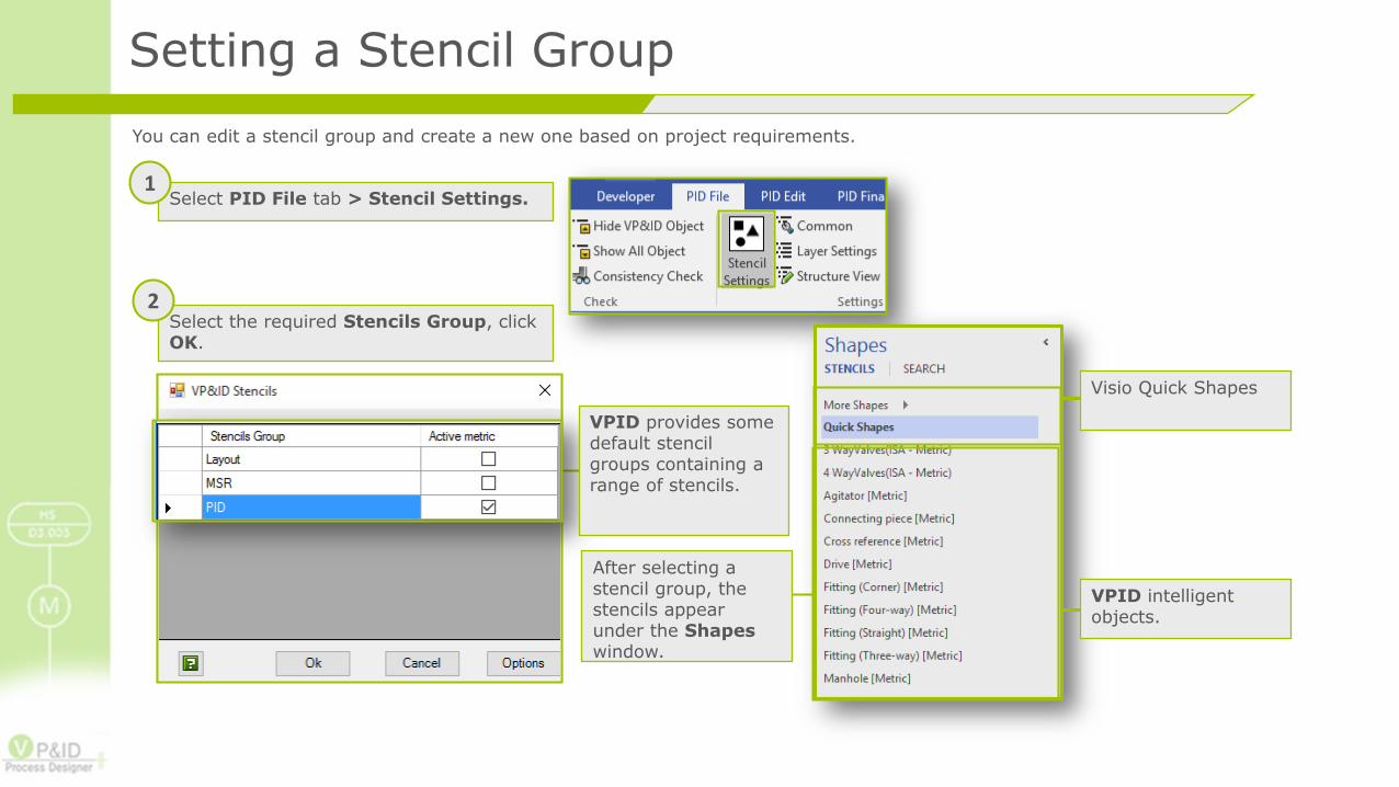
Setting a Stencil Group
You can edit a stencil group and create a new one based on project requirements.
Select PID File tab > Stencil Settings.1
Select the required Stencils Group, click OK.
2
VPID provides some default stencil groups containing a range of stencils.
After selecting a stencil group, the stencils appear under the Shapeswindow.
VPID intelligent objects.
Visio Quick Shapes

Adding Media
Project Wizard allows you to add multiple media objects. It automatically creates respective media specification object.
Select PID File > Project Wizard.1
2
3
4
Click New to add a new media to the project.
Fill in the specification for the media.
Click Change to save the changes for existing media

Placing Objects in the Drawing
Drag an object from the stencils
Drop the selected objects into the drawing area
1 2Enter the object information and click OK.
3
Note: Ensure you have selected the COM Add-Ins available in the developer tab. Failing to do so may make objects static when placing them in the drawing.

Connecting Objects with Pipes
Select PID Edit > Draw Pipeline.1
Select Media, Pipe Specification, and Nominal Bore.2
Select a connection point, drag the mouse-pointer to the next connection point and drop it.
3

Designating Objects
The Object designation command allows you to configure your object labelling. You can control the appearance and placement of the label as well.
Select PID Finalize> Object Designation.
1
Double-click to select the object property which you want to display in the label
Configure the label with free text, blank spaces, new line etc.
Using advanced settings, you can save this label as a stencil for multiple usage. Drag and place the saved label stencil whenever you require.
2

Generating Reports
You can generate reports consisting of material list and export it in various formats using the available templates.
In VPID Tree, right-click the Project node and select Reports.
1
2
3
Select a report format.
Select a report template and click OK.

Exporting Drawings
VPID allows you to export your drawings in .dwg format, which allows you to share your drawing.
Select PID File > Export > DWG/PDF/XPS Export.1
2
Enter a File name, select a Save as Type and click Save.
Note: To export drawings as CADISON DWG, you will need to contact your VPID support.

Thank You!
We would like to hear from you!
You can mail us at [email protected] and we will reach to you in one business day.
If you need any technical assistance, visit our support centre at http://www.visiopid.com/ostic/open.php.