quick start guide rex 200/250 3g|lte - helmholz benelux · assembly, installation, and...
TRANSCRIPT

Quick Start Guide REX 200/250 3G|LTE
Version
3enfrom FW 6.0.5
www.helmholz.com

Quick Start Guide REX 200/250 3G | LTE2
Content
1. Introduction 3
2. Preparation of the REX 200/250 3
3. Access to the myREX24-V2 portal 6
4. Initial router configuration via the myREX24-V2 portal 8
5. Router configuration transfer options 11
6. Connection with the machine network 14
7. Tips and tricks 16
8. Remote maintenance of Ethernet CPUs 20
9. Setting up the MPI/PROFIBUS interface (only REX 250) 21
10. Setting up VCOM-LAN for serial communications (only REX 250) 22
11. Description of LEDs and buttons 23
12. Resetting to factory settings 24
13. Configuration / factory settings from the USB stick 24
14. Alternative configuration without myREX24-V2 portal 25
15. Technical data 26

Quick Start Guide REX 200/250 3G | LTE 3
1. IntroductionThe REX 200/250 is an industrial router suitable for nearly worldwide remote access to IPv4-enabled devices (PLCs, HMIs, IP cameras, etc.). This Quick Start Guide explains the basic settings in the myREX24 portal and shows how to transfer the configuration made there to the REX 200/250.
2. Preparation of the REX 200/250
2.1 Safety instructions
Assembly, installation, and commissioning of the router may only be carried out by qualified personnel. The respective national safety and accident prevention regula-tions are to be observed. The router is built in accordance with the state of the art and the recognized technical rules relating to safety (see Declaration of conformity). The router is exclusively designed for operation in the control cabinet and with safety extra-low voltage (SELV) in accordance with IEC 60950/EN 60950/VDE 0805, and may only be connected to devices that fulfill the requirements of EN 60950. The router is only designed for use within buildings and not outdoors.
Electrostatic discharge! Note the necessary precautionary measures for the handling of electrostatically endangered building elements (EN 61340-5-1 and IEC 61340-5-1).
2.2 Installation position/minimum distances
The router is conceived of for assembly on DIN rails (pursuant to DIN EN 50 022) and is designed for control cabinet installation. Installation and assembly must take place pursuant to VDE 0100 / IEC 364. The router may only be installed in a vertical installation position.
Important advance information: Please use the most current version (as of v3.7R1.0) of the dial-up software shDIALUP for commissioning. You can acquire it as a download at www.helmholz.de.
The current firmware must be installed on all REX 200/250 routers for successful connection with the myREX24 V2 portal.
Minimum distances from neighboring modules:
P3 L
AN
P2 L
AN
P1 W
AN
P5 L
AN
P4 L
AN
Ext. V DC
18 ... 30 V
PWR
RDY
CON
STAT
FC1
FC2
FC3
FC4
FCN
RST
USB
ANT
SIM
+ FE– – +IO1 IO2 IN3 IN4
SN:
00012345
700-877-UMT01
40 mm
20 mm
40 mm
20 mm

Quick Start Guide REX 200/250 3G | LTE4
2.3 Terminals and interfacesRigid copper wires with a max. diameter of 1.5 mm² can be clamped onto theprovided connector plug. Network cables corresponding to at least category 5/5e (CAT-5) should be connected to the RJ-45 sockets. The connection with the higher level network/router to the Internet is created via the P1 WAN interface. The LAN ports P2 to P5 are available for connection to the machinery network and for com-missioning via PC.
The internal switch functionality is also active when the REX 200/250 has noconnection with the Internet.
The PWR LED lights up when the 24 V supply voltage is switched on. The bootprocess starts following the internal system check (duration of approx. 25 sec.), which is indicated by the blinking RDY LED (for approx. 90 sec.). The REX 200/250is ready for operation as soon as the RDY LED lights solid.
The terminal (FE) is for the functional earth. Connect this correctly with thereference potential.
2.3.1 2x digital inputs/outputs IO1 + IO2,as well as 2x inputs IN3 + IN4Due to the electrical isolation of these activation options, an additional 24 volt DC power supply must be applied. The alarm inputs can be activated with potential-free switches, buttons or relay contacts. Depending upon the confi guration in the my-REX24-V2 portal, 1 - 4 (up to 99 for multiplex wiring) different e-mail/SMS recipients can be notifi ed with individual notifi cation texts. For each input, confi guration can also take place for the establishing of a connection with the myREX24-V2 portal or for a system restart of the REX.
The confi gurable output wiring provides signals for the status of an active Internet, VPN, user connection of device malfunction of the REX 200/250.
Note: When using the outputs O1 or O2, the corresponding input signals I1 or I2 adopt the respective output status and can themselves then no longer be used for other external alarm input signals.
1
2
see 1
galvanically isolated
+–
application example

Quick Start Guide REX 200/250 3G | LTE 5
2.3.2 Internet access options
In the case of these device variants, a GSM mobile connection can also be configured as an alternative to the P1 WAN interface, which establishes the Internet connection via a higher level network/router. In order to be able to log into the GSM network, at least one mini SIM card of a provider of your choice must be inserted into the SIM 1 slot. The SIM card holders are found on the left side of the housing. To remove, press the unlocking button next to the insert
2.3.3 Antennas
The required GSM antennas with SMA plugs are available in Helmholz accessories. The installation location must be selected such that adequate GSM reception is pos-sible. Due to the shielding effect, antennas should not be installed in metal housings (e.g. In the control cabinet). When using antenna extensions, the instructions from the technical data sheets of the manufacturers are to be observed.
2.3.4 REX 200/250 3G (UMTS) The antenna required for radio reception is screwed onto the SMA socket “ANT”.
2.3.5 REX 200/250 LTE (4G) For radio reception, a suitable antenna must at least be screwed onto the SMA socket “MAIN”.
In order to improve the data throughput, a second antenna terminal is available on the REX 200/250 LTE router with the SMA socket “Rx” that can be used as an option. This functionality is called antenna diversity in the “WCDMA mode” and Downlink- MIMO in the “LTE mode”.
The second receiver antenna should not be located in the immediate vicinity of the main antenna. In order to improve the diversity gain and reduce other reciprocal interactions (interference effects), the two antennas should be (taking the space available in the application into account) installed with the greatest possible distance between them.
For the same reason, the second antenna should be mounted cross-polarized (rotated by 90° in relation to the main antenna).
Quick Start Guide REX 200/250 3G | LTE6
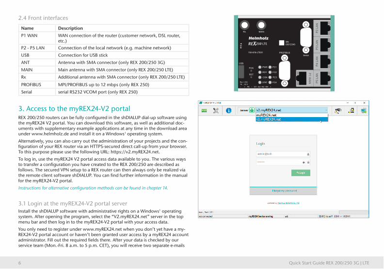
2.4 Front interfaces
Name Description
P1 WAN WAN connection of the router (customer network, DSL router, etc.)
P2 - P5 LAN Connection of the local network (e.g. machine network)
USB Connection for USB stick
ANT Antenna with SMA connector (only REX 200/250 3G)
MAIN Main antenna with SMA connector (only REX 200/250 LTE)
Rx Additional antenna with SMA connector (only REX 200/250 LTE)
PROFIBUS MPI/PROFIBUS up to 12 mbps (only REX 250)
Serial serial RS232 VCOM port (only REX 250)
3. Access to the myREX24-V2 portalREX 200/250 routers can be fully configured in the shDIALUP dial-up software using the myREX24 V2 portal. You can download this software, as well as additional doc-uments with supplementary example applications at any time in the download area under www.helmholz.de and install it on a Windows1 operating system.
Alternatively, you can also carry out the administration of your projects and the con-figuration of your REX router via an HTTPS-secured direct call-up from your browser. To this purpose please use the following URL: https://v2.myREX24.net.
To log in, use the myREX24 V2 portal access data available to you. The various ways to transfer a configuration you have created to the REX 200/250 are described as follows. The secured VPN setup to a REX router can then always only be realized via the remote client software shDIALUP. You can find further information in the manual for the myREX24-V2 portal.
Instructions for alternative configuration methods can be found in chapter 14.
3.1 Login at the myREX24-V2 portal serverInstall the shDIALUP software with administrative rights on a Windows1 operating system. After opening the program, select the “V2.myREX24.net” server in the top menu bar and then log in to the myREX24-V2 portal with your access data.
You only need to register under www.myREX24.net when you don’t yet have a my-REX24-V2 portal account or haven’t been granted user access by a myREX24 account administrator. Fill out the required fields there. After your data is checked by our service team (Mon.-Fri. 8 a.m. to 5 p.m. CET), you will receive two separate e-mails
P3 L
AN
P2 L
AN
P1 W
AN
P5 L
AN
P4 L
AN
Ext. V DC
18 ... 30 V
PWR
RDY
CON
STAT
FC1
FC2
FC3
FC4
FCN
RST
USB
Rx MAIN
PROFIBUS
Serial
SIM
+ FE– – +IO1 IO2 IN3 IN4
SN:
00012345
700-878-LTE01

Quick Start Guide REX 200/250 3G | LTE 7
with the access data. One e-mail contains the user name, the second the password.
Notes:
- Alternatively, the login page can also be reached under: https://v2.myrex24.net. Any up-to-date browser can be used for this purpose.
- Your login name consists of, for example, your user and company name separated by the @ character. Example: admin@helmholz
- Following the initial login, you will be prompted to register a new, individual password for your account.
- If necessary, you can also create and administer additional users after logging into the myREX24-V2 portal as account administrator
3.2 Navigation in the portalOnce a user has logged in for the first time, it will be guided through a tutorial. The navigation, basic settings, and the change from the simplified to the extended view are shown.
3.3 Simplified and extended viewIn the case of the menu interface of the myREX24 V2 portal, a choice can be made between two views.
The ‘simplified view’ is active for the first login. The ‘expanded view’ can be switched to at any time without changes being lost or losing their validity.
The simplified view is used for the most part in the subsequent course of the Quick Start Guide. The extended view is also presented in some places for purposes of illustration.
Expanded view:
Simplified view:

Quick Start Guide REX 200/250 3G | LTE8
4. Initial router configuration via the myREX24-V2 portalThe following describes the basic configuration steps required to set up a REX router for a VPN connection. A description of the extended functions can be found with the online help or in the manuals/white papers. You can go to the online help in the myREX24 V2 portal via the question mark symbol in the lower left area of the screen ? . When you have logged in for the first time, the myREX24 portal guides you through a brief tutorial. Please change the password for your myREX24 account following the tutorial.
4.1 Create new projectA project is the highest level for carrying out the following tasks:
- Device administration
- Remote maintenance
- Monitoring and alarms
- Data protocoling
- Visualizations
First, at least one new project needs to be created, in which a router is then assigned. Navigate to the administration with the following symbol (the tutorial also leads to this point).
An unambiguous project name is then assigned in this menu.
Additional account users, when created, can also be assigned to this project via the “Access” tab

Quick Start Guide REX 200/250 3G | LTE 9
4.2 Create new deviceA router can be added in the tree structure using the plus symbol + or with a right-click of the mouse. If a project does not yet have a router, the same function is made available in the main view by way of the green button “Create new device”. Clicking on the respective button starts the configuration assistant, which guides the user through the settings.
4.3 Configure REX 200/250 (connection data)Three simple steps are adequate for the minimal configuration of the router.
- Selection of the device type
- Network settings / modem settings
- Transfer of the configuration to the REX router
4.3.1 Step 1 “Device” – Selection of the type and nameIn the first step, the correct device type must be selected in agreement with the device order number. A freely selectable name should be assigned to this router. Permitted are only numbers and letters (0 to 9, A to Z, a to z, no spaces or special characters).

Quick Start Guide REX 200/250 3G | LTE10
4.3.2 Step 2 “Internet” – Network settingsIn step 2, the network configuration for the LAN and WAN side of the device is defined.
- LAN Each REX 200/250 comes with the LAN-side IP address 192.168.0.100/24 as a default. Modify the IP address and the subnet mask in keeping with the specifications from the machinery network to be maintained remotely.
- WAN The responsible network administrator provides you with the informa-tion necessary for the setting DHCP or static IP. DHCP is preset upon delivery.
- Modem The parameters for the APN access point (Access Point Name) of the card provider and the correct SIM PIN must be available to you and be stored here. Most providers are already available for selection (sorted by country). In the event that the correct provider is not present, the APN data can also be entered manually.
Note: If you enable DHCP, make sure that the DHCP server does not assign the IP address to a WAN port that is already active on the LAN side. IP addresses from two different subnets must be assigned to every router’s LAN and WAN ports.
4.3.3 Step 3 “Configuration” – Coupling/pairing of the router with the portal
The fundamental parameters of the minimal configuration of the REX 200/250 are now filed in the Account portal and must now be transferred to the device (See chapter 5).
Note: We recommend the “Download configuration to the PC” variant for the initial configuration.
Quick Start Guide REX 200/250 3G | LTE 11
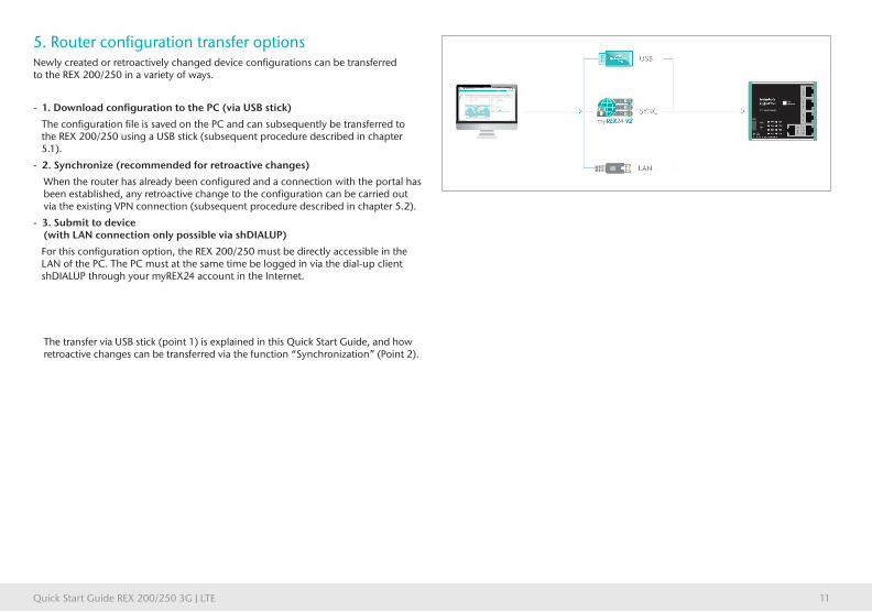
5. Router configuration transfer optionsNewly created or retroactively changed device configurations can be transferred to the REX 200/250 in a variety of ways.
- 1. Download configuration to the PC (via USB stick)
The configuration file is saved on the PC and can subsequently be transferred to the REX 200/250 using a USB stick (subsequent procedure described in chapter 5.1).
- 2. Synchronize (recommended for retroactive changes)
When the router has already been configured and a connection with the portal has been established, any retroactive change to the configuration can be carried out via the existing VPN connection (subsequent procedure described in chapter 5.2).
- 3. Submit to device(with LAN connection only possible via shDIALUP)
For this configuration option, the REX 200/250 must be directly accessible in the LAN of the PC. The PC must at the same time be logged in via the dial-up client shDIALUP through your myREX24 account in the Internet.
The transfer via USB stick (point 1) is explained in this Quick Start Guide, and how retroactive changes can be transferred via the function “Synchronization” (Point 2).

Quick Start Guide REX 200/250 3G | LTE12
5.1 Transferring the configuration using a USB flash drive
Ensure the power supply of the REX 200/250. Download the configuration file made available by the myREX24 portal via the download symbol onto your FAT-formated USB stick connected to the PC.
Note: The configuration file myrex24.mbn(x) must be filed in the root directory of your USB stick and may not be renamed.
Now carry out the steps described on page 24 in chapter 13.1 “Loading the myREX24 portal configuration”.
3. Save the configuration file
1. Log in at myREX24 V2
2. Create/edit and download the REX 300 configuration
4. Transfer the configuration
P3
LA
NP
2 L
AN
P1
WA
N
P5
LA
NP
4 L
AN
Ext. V DC
18 ... 30 V
PWR
RDY
CON
STAT
FC1
FC2
FC3
FC4
FCN
RST
USB
ANT
SIM
+ FE– – +IO1 IO2 IN3 IN4
SN:
00012345
700-877-UMT01

Quick Start Guide REX 200/250 3G | LTE 13
5.2 Synchronization
As soon as the REX 200/250 has logged into your account in the portal, you can transfer retroactive changes at any time with “Synchronize”.Where there is an existing myREX24-V2 portal connection, the REX 200/250 checks cyclically whether there is a new configuration available for its serial number and then loads it automatically. As soon as you have made a change to one or more parameters and saved it, the symbol “Device configuration is not current” appears next to the online LED. Click this symbol (or the “Synchronize” button) to start the process.
Synchronization in the simplified view:
3. Automatic synchronization1. Log in via shDIALUP
2. Create REX 300 configuration and prepare for synchronization
P3
LA
NP
2 L
AN
P1
WA
N
P5
LA
NP
4 L
AN
Ext. V DC
18 ... 30 V
PWR
RDY
CON
STAT
FC1
FC2
FC3
FC4
FCN
RST
USB
ANT
SIM
+ FE– – +IO1 IO2 IN3 IN4
SN:
00012345
700-877-UMT01
Synchronization in the extended view:

Quick Start Guide REX 200/250 3G | LTE14
The synchronization function is confirmed through the following dialog.
In this menu you can select optional user-defined settings, such as the sending of information/confirmation mails.
The REX router now adopts the new settings and restarts independently. As soon as the boot process has concluded, the REX router logs into the portal again.
6. Connection with the machine networkNote: The following steps presume that the REX 200/250 has already been configured and that you have successfully logged into your account with shDIALUP. A secured VPN connection with the end device can not be realized through the browser view (https://v2.myREX24.net).
Logged in REX 200/250 routers are identified with a green circle in the dashboard. The secured VPN connection between PC and REX router is first established by click-ing the connection button.
The active connection status with the REX 200/250 is represented with an orange animated connection button. The number of active connections activated via this account is shown in the menu bar.

Quick Start Guide REX 200/250 3G | LTE 15
Once a VPN connection to the REX 200/250 has been established, all the IPv4 packets that are valid for the applicable LAN network on the system side will be forwarded. The parameters (port, VPN-IP, LAN-IP, etc.) used for this connection are also informatively displayed in the bottom status bar.
In order to end the connection of a remote access, please click the the animated orange connection button and then confirm the disconnection of the remote connection.
Effective immediately, you can very easily view the setup of your Rex router and the function overview of the myREX24 V2 portal online.
https://youtu.be/8a1Xnu9lJ4g
Video Tutorial (3:22 min.)
Note: Other functions, such as the creation of dashboards or data point servers are described in the online help.

Quick Start Guide REX 200/250 3G | LTE16
7. Tips and tricks
7.1 Establishing of connection isn’t working7.1.1 Check device statusThe status page of the REX 200/250’s web interface shows the router’s connection status and active configuration data. To this purpose, enter the LAN IP address of the REX 200/250 into the address bar of a browser. The REX 200/250 must be accessible in LAN to this purpose, meaning that the TCP/IP address of a PC must be set for the same IP subnet. The authentication information is printed on the back of the device.
The First Start Assistant then opens. You must select “Portal server” for the myREX24 portal configuration described here. The expanded view for the “classic router” is only to be used for the configuration of own VPN connections via the device web interface.
Note: For security reasons, it is possible to deactivate the web interface on the routers. If the interface is not accessible, please check the corresponding setting in the myREX24 portal. Make sure that there are no address space conflicts with any other network interfaces (do not assign the same IP address more than once) in order to be able to communicate with the REX 200/250 .
To get more information on each step of the router connection, click on the Info icons in the status fields.

Quick Start Guide REX 200/250 3G | LTE 17
7.1.2 VPN Port (relevant for Internet access via P1 WAN interface)The REX 200/250 establishes an outbound TCP connection with the address VPN-V2.myrex24.net (5.39.123.21).
In order to be able to establish a secure connection to the myREX24-V2 server with shDIALUP or the REX 200/250, at least one of the following TCP ports (80, 1194, or 443) for the VPN tunnel must be cleared in the customer firewall. As a standard, this communication takes place via the port 1194, which is also preset.
Please clarify all setting details in advance with the responsible IT department on site. When necessary, the port in the REX 200/250 can be changed in the VPN settings.
7.1.3 Diagnostics pageIn the event of irregularities or interruptions when establishing the connection, the diagnostics page supports you with troubleshooting. In the event of an error, the technical support of Helmholz requires the respective result from the individual and autonomous test functions.

Quick Start Guide REX 200/250 3G | LTE18
7.1.4 Is a MAC address filter activated in the firewall? (relevant for Internet access via P1 WAN interface)It may be necessary to approve the MAC address of the REX 200/250 in the higher level DSL modem or the firewall. If it should not be possible to establish a connec-tion, please ask your responsible network administrator whether such a MAC address filter has been activated.
7.1.5 Is the connection being established via a proxy? (relevant for Internet access via P1 WAN interface)In the event that a connection is not successfully established in the customer net-work, it might be the case that the necessary proxy settings have not been filed or are incorrect. These can be adjusted on the configuration page of the REX 200/250 in the Internet settings.
7.1.6 no or inadequate mobile communications connectionIn the event that the connection of your REX 200/250 router with the portal is not established for mobile communications remote maintenance or is interrupted during operation, the following parameters, among others, should be checked:
- incorrect SIM PIN stored in the router
- no credit on prepaid SIM cards
- blocked ports (dependent upon provider)
- impaired GSM reception quality due to unfavorable antenna location
- selection of an antenna with inadequate transmission/receiving performance

Quick Start Guide REX 200/250 3G | LTE 19
7.2 Device configuration: Services – NTP serverFor purposes of the internal system time of the REX 200/250, this carries out a com-parison via a time server in the Internet at regular intervals. Where necessary, you can individually set the preset NTP server entry and the interval.
Note: Various functions in the myREX24 portal require a current time setting in the REX 200/250.
7.3 Device configuration: Services - Mail settings (relevant for Internet access via P1 WAN interface) If you would like to use the function of the REX 200/250 for the automatic sending of e-mails, port 25 (SMTP) may not be blocked in the firewall of the customer network. You can also use alternative e-mail servers to send e-mails.
Quick Start Guide REX 200/250 3G | LTE20
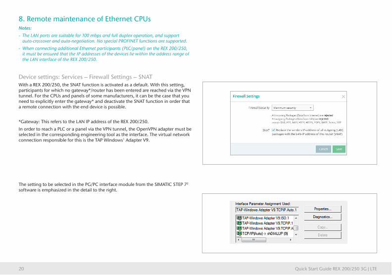
8. Remote maintenance of Ethernet CPUsNotes:
- The LAN ports are suitable for 100 mbps and full duplex operation, and support auto-crossover and auto-negotiation. No special PROFINET functions are supported.
- When connecting additional Ethernet participants (PLC/panel) on the REX 200/250, it must be ensured that the IP addresses of the devices lie within the address range of the LAN interface of the REX 200/250.
Device settings: Services – Firewall Settings – SNATWith a REX 200/250, the SNAT function is activated as a default. With this setting, participants for which no gateway*/router has been entered are reached via the VPN tunnel. For the CPUs and panels of some manufacturers, it can be the case that you need to explicitly enter the gateway* and deactivate the SNAT function in order that a remote connection with the end device is possible.
*Gateway: This refers to the LAN IP address of the REX 200/250.
In order to reach a PLC or a panel via the VPN tunnel, the OpenVPN adapter must be selected in the corresponding engineering tool as the interface. The virtual network connection responsible for this is the TAP Windows1 Adapter V9.
The setting to be selected in the PG/PC interface module from the SIMATIC STEP 72 software is emphasized in the detail to the right.

Quick Start Guide REX 200/250 3G | LTE 21
9. Setting up the MPI/PROFIBUS interface (only REX 250)The following steps are necessary to be able to carry out remote maintenance for a S7 MPI/PROFIBUS PLC with the REX 250:
9.1 Install driverPlease install the NETLink®-S7-NET driver on your remote maintenance computer. The driver can be found on the enclosed CD or the current version downloaded at www.helmholz.de.
9.2 Create station
Following successful installation, the access paths of the “NETL ink® PRO Family” are available in the PG/PC interface.
Note: The general assignments must also first be carried out in the PG/PC interface (accessible via the Windows Control Panel) for the TIA Portal¹.
Select a configuration (MPI/PPI or PROFIBUS) and open the “Properties…” page.
9.3 Assign IP address and nameClick the “New” button under the “Local Connection” tab to add the REX 250. Enter the LAN IP address and the name of the router into the corresponding input fields. The internal communications adapter can be reached with these settings both locally via LAN and via VPN. Then click on ”OK”.
Note: Please note that the port required by the REX 200/250 in order to communicate using the driver is approved by default. The “Internet teleservice” function may not be activated!
Following the adoption of the settings, it is possible to reach devices at the MPI/PROFIBUS port of the REX 250. Selection takes place via “Set PG/PC interface” in the programming software.
Quick Start Guide REX 200/250 3G | LTE22
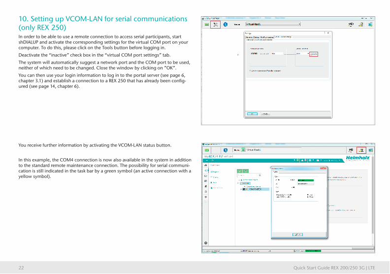
10. Setting up VCOM-LAN for serial communications (only REX 250)In order to be able to use a remote connection to access serial participants, start shDIALUP and activate the corresponding settings for the virtual COM port on your computer. To do this, please click on the Tools button before logging in.
Deactivate the “inactive” check box in the “virtual COM port settings” tab.
The system will automatically suggest a network port and the COM port to be used, neither of which need to be changed. Close the window by clicking on ”OK”.
You can then use your login information to log in to the portal server (see page 6, chapter 3.1) and establish a connection to a REX 250 that has already been config-ured (see page 14, chapter 6).
You receive further information by activating the VCOM-LAN status button.
In this example, the COM4 connection is now also available in the system in addition to the standard remote maintenance connection. The possibility for serial communi-cation is still indicated in the task bar by a green symbol (an active connection with a yellow symbol).
Quick Start Guide REX 200/250 3G | LTE 23
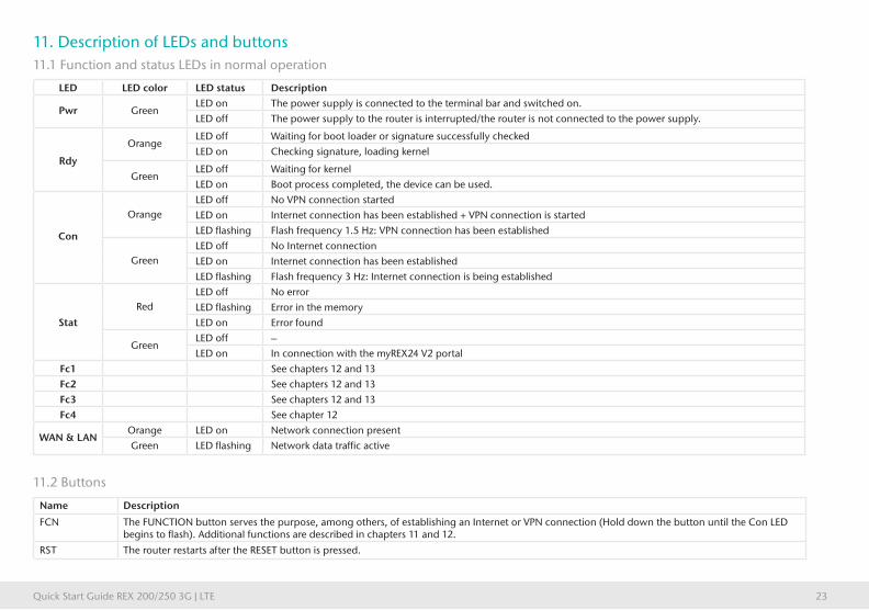
11. Description of LEDs and buttons11.1 Function and status LEDs in normal operation
LED LED color LED status Description
Pwr GreenLED on The power supply is connected to the terminal bar and switched on.LED off The power supply to the router is interrupted/the router is not connected to the power supply.
Rdy
OrangeLED off Waiting for boot loader or signature successfully checkedLED on Checking signature, loading kernel
GreenLED off Waiting for kernelLED on Boot process completed, the device can be used.
Con
OrangeLED off No VPN connection startedLED on Internet connection has been established + VPN connection is startedLED flashing Flash frequency 1.5 Hz: VPN connection has been established
GreenLED off No Internet connectionLED on Internet connection has been establishedLED flashing Flash frequency 3 Hz: Internet connection is being established
Stat
Red
LED off No errorLED flashing Error in the memory
LED on Error found
GreenLED off –
LED on In connection with the myREX24 V2 portal
Fc1 See chapters 12 and 13
Fc2 See chapters 12 and 13
Fc3 See chapters 12 and 13
Fc4 See chapter 12
WAN & LANOrange LED on Network connection presentGreen LED flashing Network data traffic active
11.2 Buttons
Name Description
FCN The FUNCTION button serves the purpose, among others, of establishing an Internet or VPN connection (Hold down the button until the Con LED begins to flash). Additional functions are described in chapters 11 and 12.
RST The router restarts after the RESET button is pressed.
Quick Start Guide REX 200/250 3G | LTE24
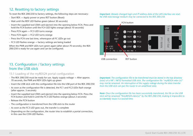
12. Resetting to factory settingsTo reset the REX 200/250 to factory settings, the following steps are necessary:
- Start REX -> Apply power or press RST button (Reset)
- Wait until the RDY LED flashes green (about 30 seconds)
- Insert the supplied tool (SIM card ejector) into the opening below FCN. Press and hold the FCN button until the FC4 LED lights orange (about 10 seconds)
- Press FCN again -> FC3 LED turns orange
- Press FCN again -> FC2 LED turns orange
- Press the FCN one last time, whereupon all FC LEDs go out
- FC3 LED flashes orange -> factory settings are being loaded
When the PWR and RDY LEDs turn green again (after about 70 seconds), the REX 200/250 is ready for use again and can be configured.
13. Configuration / factory settings from the USB stick13.1 Loading of the myREX24 portal configuration - The REX 200/250 must be ready for use. Apply supply voltage -> After approx. 70 seconds, the PWR and RDY LEDs light up green
- Insert the USB stick with the configuration file into the USB port of the REX 200/250
- As soon as the configuration file is detected, the FC1 and FC2 LEDs flash orange (after approx. 3 seconds)
- Insert the supplied tool (SIM card ejector) into the opening below FCN. Press the FCN button and hold it until the FC3 LED flashes orange (about 2 seconds)
- Release the FCN button
- The configuration is transferred from the USB stick to the router
- As soon as the FC3 LED goes out, the transfer is complete
- Depending on the configuration, the router tries to establish a portal connection, in this case the CON LED flashes.
Important: Already changed login and IP address data of the LAN interface are reset. No USB stick/storage medium may be connected to the REX 200/250.
Important: The configuration file to be transferred must be stored in the top directory (root) of a FAT / FAT32 formatted USB stick. The configuration file "myREX24.mbn (x)" may not be renamed. An interruption of the supply voltage during the data transfer from the USB stick can put the router in an undefined state.
Note: Once the configuration file has been successfully transferred, the file on the USB stick will be renamed “XmyREX24.mbn(x)” by the REX 200/250, making it impossible to accidentally reuse it a second time.
P1
WA
N
P5
LA
N
Ext. V DC
18 ... 30 V
PWR
RDY
CON
STAT
FC1
FC2
FC3
FC4
FCN
RST
USB
+ FE– – +IO1 IO2 IN3 IN4
FCN button
RST buttonUSB connection

Quick Start Guide REX 200/250 3G | LTE 25
13.2 Loading of a firmware file (Update) - The REX 200/250 must be ready for operation. Apply supply voltage -> After approx. 70 seconds the PWR and RDY LEDs light up
- Insert the USB stick with the firmware file into the USB port of the REX 200/250
- As soon as the firmware file is detected, the FC1 and FC3 LEDs flash orange (after approx. 5 seconds)
- Insert the supplied tool (SIM card ejector) into the opening below FCN. Press the FCN key and hold it until the FC2 LED flashes orange (about 2 seconds)
- Release the FCN button
- The firmware is transferred from the USB stick to the router (Duration approx. 15 seconds)
- As soon as the FC2 LED goes out, the transfer is complete
- A reboot of the REX 200/250 is performed automatically and the process is complete when the PWR and RDY LEDs are lit solid.
14. Alternative configuration without myREX24-V2 portalIf you want to use the REX 200/250 without our mediation server "myREX24 V2", you can also use another OpenVPN software or e.g. set up the IPsec encryption embedded in your hardware. If you have selected the selection for the classic router in the "First Start" screen, you can reach the corresponding step by step configurator of the web interface via the menu item "Wizards" in the upper right corner.
For the aforementioned parameterization options are appropriate Documents with application examples under www.helmholz.com free of charge available for download.
Important: An interruption of the supply voltage during the data transfer Transferring from the USB stick can put the router in an undefined state! The firmware to be transfer-red must be stored in the top directory (root) of a FAT / FAT32 formatted USB stick. The firmware file "image.swux" must not be renamed.
Note: If both the firmware and a myREX24 portal configuration are found on the USB stick, the firmware is always first recognized by the REX 200/250 (Fc1 + Fc3 flashes). If you don’t press the FCN button within 10 seconds, the REX 200/250 changes to the configuration file (Fc1 + Fc2 flash). If you here too don’t react within 10 seconds, the router once again reverts to the normal mode.

Quick Start Guide REX 200/250 3G | LTE26
15. Technical data
Performance data
Voltage V (DC) 24 V DC, 18... 28 V DC
Current draw Max. 160 mA @ DC 24 V
Protection rating IP IP 20
Location of use Dry location
Temperature (operating) -40 – +75 °C
Temperature (warehouse) -40 – +85 °C
Humidity 0 - 95%, non-condensing
Real-time clock In the event of a power failure, date and time of day are retained for up to 7 days (depending upon the ambient temperature).
Dimensions (max.) REX 250: 75 mm x 100 mm x 35 mm (H x W x D) / REX 200: 75 mm x 89 mm x 35 mm (H x W x D)
Weight (max.) REX 200: 220 g / REX 250: 250 g
Power dissipation (max.) 4 watts
Installation DIN rail assembly pursuant to DIN EN50022
I/Os and standard interfaces
Digital inputs 4 pieces, DIN EN 61131-2 Type 3
Digital input/outputs 2 pieces, max. 0.5 A for each output
LAN interfaces 4 pieces, 10/100 mbps full and semi-duplex operation, automatic detection patch cable / crossover cable (auto-detection)
USB interface USB host 2.0 TypeA
SD card slot currently being prepared
VPN
VPN protocol IPsec/PPTP/OpenVPN, 64 tunnel
Encryption Method Blowfish, AES, DES/3DES
Encryption algorithms MD5, SHA1
Authentication Pre-shared key, X.509
Network/security
Firewall 1:1 NAT, IP filter, port forwarding, stateful inspection
IP router NAT IP, TCP/IP routing, IP forwarding
Services DHCP server, DHCP client, DNS server, NTP client, PPP server, DynDNS
Time comparison NTP server

Quick Start Guide REX 200/250 3G | LTE 27
Optional interfaces REX 250
Interface 1 (Serial) RS-232/422/485 (can be switched with software)
Interface 2 (PROFIBUS) SIM card slots
RS-232/485 (can be switched with software) PC adapter or MPI/PROFIBUS driver up to 12 mbps 2x SIM card reader for mini-SIM 1.8V/3V
Communication
WAN interface 10/100 mbps full and semi-duplex operation, automatic detection patch cable / crossover cable (auto-detection)
Devices with UMTS (3G) modem Quadband GPRS/EDGE Data Interface
GSM frequency bands GSM/GPRS/EDGE: 850, 900, 1800, 1900
UMTS frequency bands UMTS/HSPA: (B5)800/850, (B8)900, (B4)AWS 1700, (B2)1900, (B1)2100 Klasse 1
Antenna terminal 1 piece SMA-connector
Data transmission rate HSPA+ (Upload 5,76 Mbit/s | Download 21,0Mbit/s)
Transmit power Class 1, E2, 3, 4
Devices with LTE (4G) modem EU Multiband GSM/GPRS/WCDMA/LTE Data
GSM frequency bands GSM 900, DCS1800
GSM/GPRS/EDGE 900, 1800 MHz; max. 236 kbps
UMTS frequency bands B5(850), B8 (900), B1 (2100)
LTE frequency bands B20 (800), B3 (1800), B7 (2600)
Antenna terminals 2 pieces SMA-connector
Data transmission rate HSPA+ (Upload 5,76 Mbit/s | Download 42,0 Mbit/s);
LTE (Upload 50 Mbit/s | Download 100 Mbit/s)
Transmit power Class 1, E2, 3, 4

Helmholz GmbH & Co. KG | Hannberger Weg 2 | 91091 Großenseebach | Germany | Phone +49 9135 7380-0 | Fax +49 9135 7380-110 | [email protected] | www.helmholz.com
The contents of this Quick Start Guide have been checked by us so as to ensure that they match the hardware and software described. However, we assume no liability for any existing differences, as these cannot be fully ruled out.
The information in this Quick Start Guide is, however, updated on a regular basis. When using your purchased products, please make sure to use the latest version of this Quick Start Guide, which can be viewed and downloaded on the Internet at www.helmholz.de. Our customers are important to us. We are pleased to receive suggestions for improvement and new impulses.
This product was created with open source software. The licensing conditions for the open source software used can be found in the download area of the product at www.helmholz.de. You can receive a compilation of the open source software used as a DVD for up to 3 years following the purchase of the product for a contribution of €30 plus shipping costs when you send us an e-mail.
1) Windows is a registered trademark of the Microsoft Corporation.
2) Simatic and STEP 7 are registered trademarks of Siemens AG.