quick start guide - nxp semiconductorsquick start guide. quick start guide 2 3-phase sensorless bldc...
TRANSCRIPT
3-Phase Sensorless BLDC Motor Control Development Kit with MC9S12G128 MCU
Quick Start Guide

Quick Start Guide
2
3-Phase Sensorless BLDC Motor Control Development Kit with MC9S12G128 MCU
3-Phase BLDC Motor
MC9S12G128 Controller Board
3-Phase Low-Voltage Power Stage

3
3-Phase Sensorless BLDC Motor Control Development Kit Features• MC9S12G128 MCU (100-pin LQFP)
• MC33905S system basis chip
• MC33937A FET pre-driver
• Sensorless BLDC motor control support
• Hardware support for Hall sensor-based motor control
• DC-bus overvoltage, overcurrent and undervoltage detection
• FreeMASTER instrumentation/visualization

Quick Start Guide
4
3-Phase Low-Voltage Power Stage
Motor Connector
UNI-3 Interface
MC33937A Interface
MC33937A Overcurrent Threshold Setup
Brake Resistor
Power Supply Connector
Power Supply Terminal
5
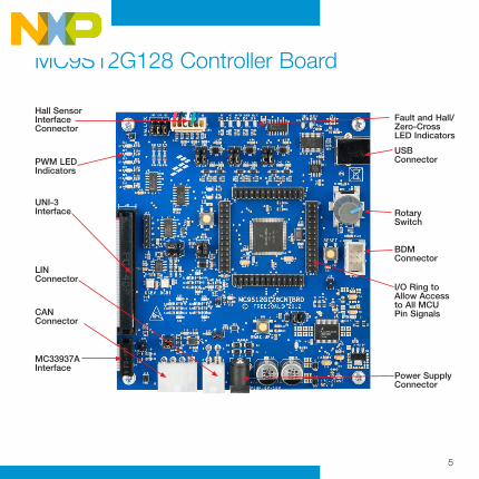
MC9S12G128 Controller Board
Fault and Hall/Zero-Cross LED Indicators
USB Connector
BDM Connector
I/O Ring to Allow Access to All MCU Pin Signals
Power Supply Connector
Rotary Switch
Hall Sensor Interface Connector
PWM LED Indicators
UNI-3 Interface
LIN Connector
CAN Connector
MC33937A Interface
Quick Start Guide
6
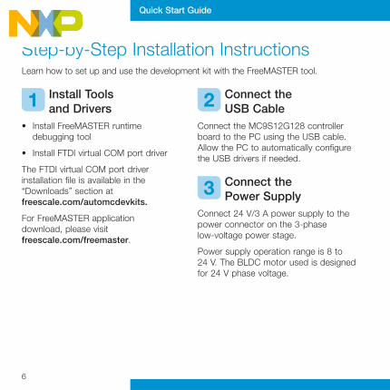
Step-by-Step Installation Instructions Learn how to set up and use the development kit with the FreeMASTER tool.
Install Tools and Drivers
• Install FreeMASTER runtime debugging tool
• Install FTDI virtual COM port driver
The FTDI virtual COM port driver installation file is available in the “Downloads” section at freescale.com/automcdevkits.
For FreeMASTER application download, please visit freescale.com/freemaster.
Connect the USB Cable
Connect the MC9S12G128 controller board to the PC using the USB cable. Allow the PC to automatically configure the USB drivers if needed.
Connect the Power Supply
Connect 24 V/3 A power supply to the power connector on the 3-phase low-voltage power stage.
Power supply operation range is 8 to 24 V. The BLDC motor used is designed for 24 V phase voltage.
1 2
3
7
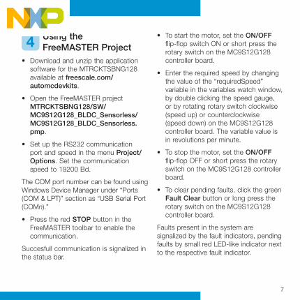
Using the FreeMASTER Project
• Download and unzip the application software for the MTRCKTSBNG128 available at freescale.com/automcdevkits.
• Open the FreeMASTER project MTRCKTSBNG128/SW/ MC9S12G128_BLDC_Sensorless/ MC9S12G128_BLDC_Sensorless.pmp.
• Set up the RS232 communication port and speed in the menu Project/Options. Set the communication speed to 19200 Bd.
The COM port number can be found using Windows Device Manager under “Ports (COM & LPT)” section as “USB Serial Port (COMn).”
• Press the red STOP button in the FreeMASTER toolbar to enable the communication.
Succesfull communication is signalized in the status bar.
• To start the motor, set the ON/OFF flip-flop switch ON or short press the rotary switch on the MC9S12G128 controller board.
• Enter the required speed by changing the value of the “requiredSpeed” variable in the variables watch window, by double clicking the speed gauge, or by rotating rotary switch clockwise (speed up) or counterclockwise (speed down) on the MC9S12G128 controller board. The variable value is in revolutions per minute.
• To stop the motor, set the ON/OFF flip-flop OFF or short press the rotary switch on the MC9S12G128 controller board.
• To clear pending faults, click the green Fault Clear button or long press the rotary switch on the MC9S12G128 controller board.
Faults present in the system are signalized by the fault indicators, pending faults by small red LED-like indicator next to the respective fault indicator.
4
Quick Start Guide for TWRPI-MMA845xQQuick Start Guide
8
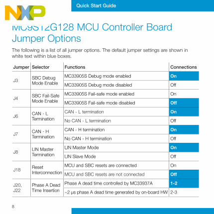
MC9S12G128 MCU Controller Board Jumper Options The following is a list of all jumper options. The default jumper settings are shown in white text within blue boxes.
Jumper Selector Functions Connections
J3 SBC Debug Mode Enable
MC33905S Debug mode enabled On
MC33905S Debug mode disabled Off
J4 SBC Fail-Safe Mode Enable
MC33905S Fail-safe mode enabled On
MC33905S Fail-safe mode disabled Off
J6 CAN - L Termination
CAN - L termination On
No CAN - L termination Off
J7 CAN - H Termination
CAN - H termination On
No CAN - H termination Off
J8 LIN Master Termination
LIN Master Mode On
LIN Slave Mode Off
J18 Reset Interconnection
MCU and SBC resets are connected On
MCU and SBC resets are not connected Off
J20, J22
Phase A Dead Time Insertion
Phase A dead time controlled by MC33937A 1-2
~2 μs phase A dead time generated by on-board HW 2-3
9
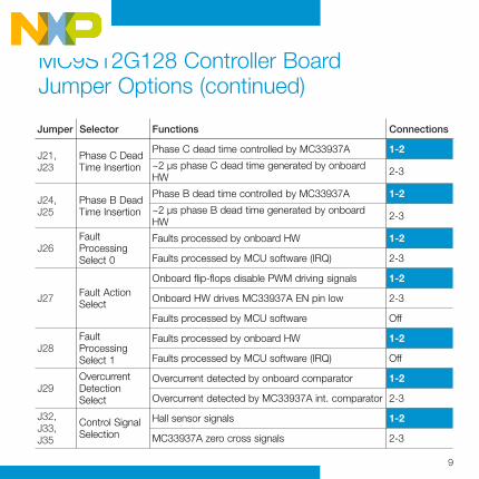
MC9S12G128 Controller Board Jumper Options (continued)
J21, J23
Phase C Dead Time Insertion
Phase C dead time controlled by MC33937A 1-2
~2 μs phase C dead time generated by onboard HW 2-3
J24, J25
Phase B Dead Time Insertion
Phase B dead time controlled by MC33937A 1-2
~2 μs phase B dead time generated by onboard HW 2-3
J26Fault Processing Select 0
Faults processed by onboard HW 1-2
Faults processed by MCU software (IRQ) 2-3
J27 Fault Action Select
Onboard flip-flops disable PWM driving signals 1-2
Onboard HW drives MC33937A EN pin low 2-3
Faults processed by MCU software Off
J28Fault Processing Select 1
Faults processed by onboard HW 1-2
Faults processed by MCU software (IRQ) Off
J29Overcurrent Detection Select
Overcurrent detected by onboard comparator 1-2
Overcurrent detected by MC33937A int. comparator 2-3
J32, J33, J35
Control Signal Selection
Hall sensor signals 1-2
MC33937A zero cross signals 2-3
Jumper Selector Functions Connections

Quick Start Guide
For more information, visit freescale.com/automcdevkits
Freescale and the Freescale logo are trademarks of Freescale semiconductor, Inc., Reg. U.S. Pat. & Tm. Off. All other product or service names are the property of their respective owners. © 2012 Freescale Semiconductor, Inc.
Doc Number: MTRCKTSBNG128QSG REV 0
Quick Start Guide
SupportVisit freescale.com/support for a list of phone numbers within your region.
WarrantyVisit freescale.com/warranty for complete warranty information.
Quick Start Guide