quick reference specification book · 2018-12-16 · audi tt quick reference specification book •...
TRANSCRIPT

2014
TTQuick Reference Specification Book


Audi TT Quick Reference Specification Book • October 2013 i
2014 Audi TT Quick Reference Specification Book
TABle of ConTenTS
General Information ...................................................... 1Decimal and Metric Equivalents ...........................................1Tightening Torque .................................................................2Warnings and Cautions ........................................................4
Vehicle Identification ..................................................... 9Vehicle Identification Number (VIN) Location ..........................9VIN Decoder ..........................................................................10Vehicle Data Label .................................................................11
Sales Codes ................................................................. 12Engine Codes ........................................................................12Transmission Codes ..............................................................12
Vehicle Lifting .............................................................. 13Hoist and Floor Jack Lifting Points ........................................13Front ......................................................................................13Rear .......................................................................................13
ENGINES Engine Mechanical – 2.0L CETA ................................. 14
General, Technical Data ....................................................14Engine Number Location .......................................................14Engine Data ...........................................................................14
Engine Assembly – 2.0L CETA ...........................................15Fastener Tightening Specifications ........................................15
Crankshaft, Cylinder Block – 2.0L CETA ............................16Cylinder Block Bearing Shell Identification ............................16Bearing Cap Bearing Shell Identification ...............................18Fastener Tightening Specifications ........................................19Crankshaft Dimensions .........................................................19Piston Ring End Gaps ...........................................................19Piston Ring Clearance ...........................................................19Piston and Cylinder Dimensions ............................................20Accessory Assembly Bracket Tightening Specifications ........20Sealing Flange Tightening Specifications ..............................21Crankshaft Assembly Tightening Specifications ....................22

ii Audi TT Quick Reference Specification Book • October 2013
Cylinder Head, Valvetrain – 2.0L CETA ..............................23Fastener Tightening Specifications ........................................23Valve Dimensions ..................................................................24Compression Pressures ........................................................24Cylinder Head Removal Specifications (with AVS) ................25Cylinder Head Removal Specifications (without AVS) ...........25Cylinder Head Tightening Specifications (with AVS) .............26Cylinder Head Tightening Specifications (without AVS) ........27Cylinder Head Cover Removal Specifications .......................28Cylinder Head Cover Tightening Specifications ....................29Crankcase Ventilation Tightening Specification .....................30Upper Timing Chain Cover Tightening Specification .............31Lower Timing Chain Cover Tightening Specifications ...........32
Lubrication – 2.0L CETA .....................................................33Fastener Tightening Specifications ........................................33Upper Oil Pan Tightening Specifications ...............................34Oil Pan Tightening Specifications ..........................................35Oil Separator Tightening Specification ..................................36
Cooling System – 2.0L CETA .............................................36Fastener Tightening Specifications ........................................36Coolant Pump Tightening Specification .................................37
Fuel Supply – 2.0L CETA ....................................................38Fastener Tightening Specifications ........................................38
Turbocharger, G-Charger – 2.0L CETA ..............................39Fastener Tightening Specifications ........................................39Turbocharger Tightening Specifications ................................40
Exhaust System – 2.0L CETA .............................................40Fastener Tightening Specifications ........................................40
Multiport Fuel Injection – 2.0L CETA ..................................41Technical Data .......................................................................41Fastener Tightening Specifications ........................................41
Ignition/Glow Plug System – 2.0L CETA .............................42Technical Data .......................................................................42Fastener Tightening Specifications ........................................42
Engine Mechanical – 2.0L CDMA ............................... 43General, Technical Data ....................................................43
Engine Number Location .......................................................43Engine Data ...........................................................................45
Engine Assembly – 2.0L CDMA ..........................................46Fastener Tightening Specifications ........................................46

Audi TT Quick Reference Specification Book • October 2013 iii
Crankshaft, Cylinder Block – 2.0L CDMA ...........................47Cylinder Block Bearing Shell Identification ............................47Bearing Cover Bearing Shell Identification ............................48Fastener Tightening Specifications ........................................49Crankshaft Dimensions .........................................................49Piston Ring End Gaps ...........................................................49Piston Ring Clearance ...........................................................49Piston and Cylinder Dimensions ............................................50Accessory Assembly Bracket Tightening Specifications ........50Ribbed Belt Pulley Side Sealing Flange Tightening
Specifications ..................................................................51Ribbed Belt Transmission Side Sealing Flange Tightening
Specifications ..................................................................52Cylinder Head, Valvetrain – 2.0L CDMA .............................53
Fastener Tightening Specifications ........................................53Valve Dimensions ..................................................................54Compression Pressures ........................................................54Cylinder Head Tightening Specifications ...............................55Cylinder Head Cover Tightening Specifications ....................56Guide Frame Tightening Specifications .................................57
Lubrication – 2.0L CDMA ....................................................58Fastener Tightening Specifications ........................................58Oil Pan Tightening Specifications ..........................................58Balance Shaft Housing Bolts .................................................59Balance Shaft Housing Tightening Specifications .................60
Cooling System – 2.0L CDMA ............................................61Fastener Tightening Specifications ........................................61
Fuel Supply – 2.0L CDMA ..................................................62Fastener Tightening Specifications ........................................62
Turbocharger, G-Charger – 2.0L CDMA .............................63Fastener Tightening Specifications ........................................63
Exhaust System – 2.0L CDMA ...........................................64Fastener Tightening Specifications ........................................64
Fuel Injection and Ignition – 2.0L CDMA ............................64Technical Data .......................................................................64Fastener Tightening Specifications ........................................65
TRANSMISSIONS S tronic Transmission – 02E....................................... 66
General, Technical Data .....................................................66Transmission Identification ....................................................66

iv Audi TT Quick Reference Specification Book • October 2013
Code Letters, Transmission Allocations, Ratios and Equipment .......................................................................67
Controls, Housing – 02E .....................................................72Fastener Tightening Specifications ........................................72Transmission to Engine Tightening Specifications ................74
Gears, Shafts – 02E ...........................................................75Fastener Tightening Specifications ........................................75Mechatronic Tightening Specifications ..................................76Fastener Tightening Specifications ........................................77Bevel Box Bracket for Vehicles with 2.0L TFSI Tightening
Specifications ..................................................................77
Rear Final Drive – 02D, 0AV, 0BR, 0BS, 0BY ............. 78General, Technical Data .....................................................78
Rear Final Drive 02D Identification ........................................78Example of Identifications on A Rear Final Drive “02D” .........79Rear Final Drive 0BR or 0BY Identification............................81Rear Final Drive 0BS Identification ........................................82Rear Final Drive Transmission Allocations, Ratios,
Capacities .......................................................................82Fastener Tightening Specifications ........................................84Pendulum Support First to Transmission Tightening
Specifications ..................................................................85Pendulum Support to Transmission Tightening
Specifications ..................................................................86
CHASSIS Suspension, Wheels, Steering ................................... 87
General, Technical data ......................................................87Chassis ..................................................................................87Steering .................................................................................87
Front Suspension ...............................................................87Fastener Tightening Specifications ........................................87
Rear Suspension ................................................................89Fastener Tightening Specifications ........................................89
Wheels, Tires ......................................................................91Fastener Tightening Specifications ........................................91
Wheel Alignment Data ........................................................91Wheel Alignment Specified Values ........................................91
Steering ..............................................................................93Fastener Tightening Specifications ........................................93

Audi TT Quick Reference Specification Book • October 2013 v
Brake System ............................................................... 94General, Technical Data .....................................................94
Brakes ...................................................................................94Front Wheel Brakes – Technical Data ...................................94TT RS Front Wheel BrakesWheel Brakes – Technical Data ..95TT RS Rear Wheel Brakes ....................................................97
Anti-lock Brake System (ABS) ............................................97Fastener Tightening Specifications ........................................97
Mechanical Components ....................................................98Fastener Tightening Specifications ........................................98
Hydraulic Components .......................................................99Hydraulic Tightening Specifications .......................................99
Body ............................................................................ 100Air Gap Body Dimensions ................................................100
Front Gap Dimensions .........................................................100Rear Gap Dimensions .........................................................101
Body Exterior ....................................................................102Body Front Tightening Specifications ..................................102Hood, Lids Tightening Specifications ...................................102Front Doors, Central Locking System Tightening
Specifications ................................................................103Convertible Top Tightening Specifications ...........................103Bumpers Tightening Specifications .....................................104Glass, Window Regulators Tightening Specifications .........105Exterior Equipment Tightening Specifications .....................105
Body Interior .....................................................................107Interior Equipment Tightening Specifications ......................107Passenger Protection, Airbags, Seat Belts Tightening
Specifications ................................................................107Interior Trim Tightening Specifications .................................108Seat Frames Tightening Specifications ...............................110
Heating, Ventilation & Air Conditioning ...................112General, Technical Data ...................................................112
Refrigerant Oil Distribution ..................................................112Refrigerant R134a Vapor Pressure Table ............................113
Air Conditioning ................................................................114Fastener Tightening Specifications ......................................114
vi Audi TT Quick Reference Specification Book • October 2013
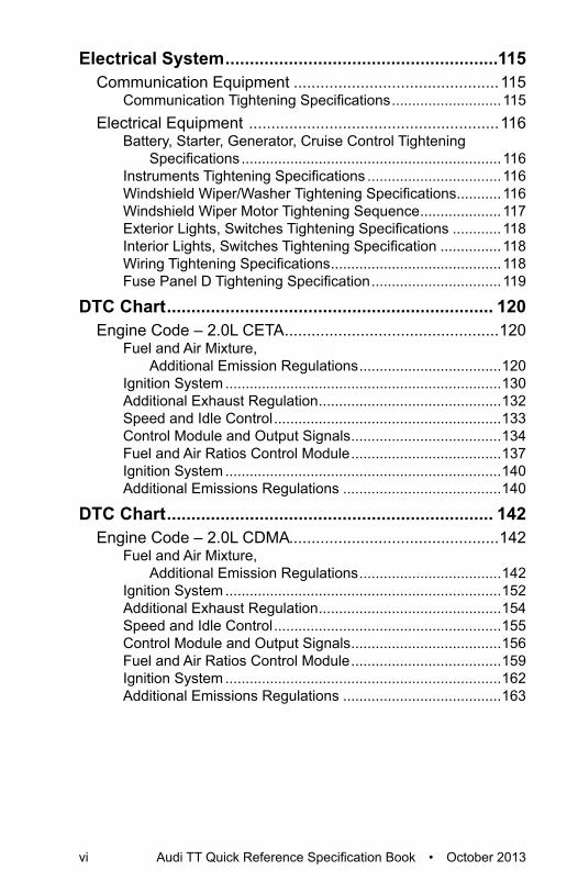
Electrical System ........................................................115Communication Equipment ..............................................115
Communication Tightening Specifications ...........................115Electrical Equipment ........................................................116
Battery, Starter, Generator, Cruise Control Tightening Specifications ................................................................116
Instruments Tightening Specifications .................................116Windshield Wiper/Washer Tightening Specifications ...........116Windshield Wiper Motor Tightening Sequence ....................117Exterior Lights, Switches Tightening Specifications ............118Interior Lights, Switches Tightening Specification ...............118Wiring Tightening Specifications ..........................................118Fuse Panel D Tightening Specification ................................119
DTC Chart ................................................................... 120Engine Code – 2.0L CETA ................................................120
Fuel and Air Mixture, Additional Emission Regulations ...................................120
Ignition System ....................................................................130Additional Exhaust Regulation .............................................132Speed and Idle Control ........................................................133Control Module and Output Signals .....................................134Fuel and Air Ratios Control Module .....................................137Ignition System ....................................................................140Additional Emissions Regulations .......................................140
DTC Chart ................................................................... 142Engine Code – 2.0L CDMA...............................................142
Fuel and Air Mixture, Additional Emission Regulations ...................................142
Ignition System ....................................................................152Additional Exhaust Regulation .............................................154Speed and Idle Control ........................................................155Control Module and Output Signals .....................................156Fuel and Air Ratios Control Module .....................................159Ignition System ....................................................................162Additional Emissions Regulations .......................................163

Gen
eral
Info
rmat
ion
Audi TT Quick Reference Specification Book • October 2013 1
GENERAL INFORMATIONDecimal and Metric EquivalentsDistance/Length
To calculate: mm x 0.03937 = in.mm in. mm in. mm in. mm in.0.002 0.00008 0.01 0.0004 0.1 0.004 1 0.040.004 0.00016 0.02 0.0008 0.2 0.008 2 0.080.006 0.00024 0.03 0.0012 0.3 0.012 3 0.120.008 0.00031 0.04 0.0016 0.4 0.016 4 0.160.010 0.00039 0.05 0.0020 0.5 0.020 5 0.200.020 0.00079 0.06 0.0024 0.6 0.024 6 0.240.030 0.00118 0.07 0.0028 0.7 0.028 7 0.280.040 0.00157 0.08 0.0031 0.8 0.031 8 0.310.050 0.00197 0.09 0.0035 0.9 0.035 9 0.350.060 0.00236 0.10 0.0039 1.0 0.039 10 0.390.070 0.00276 0.20 0.0079 2.0 0.079 20 0.790.080 0.00315 0.30 0.0118 3.0 0.118 30 1.180.090 0.00354 0.40 0.0157 4.0 0.157 40 1.570.100 0.00394 0.50 0.0197 5.0 0.197 50 1.970.200 0.00787 0.60 0.0236 6.0 0.236 60 2.360.300 0.01181 0.70 0.0276 7.0 0.276 70 2.760.400 0.01575 0.80 0.0315 8.0 0.315 80 3.150.500 0.01969 0.90 0.0354 9.0 0.354 90 3.540.600 0.02362 1.00 0.0394 10.0 0.394 100 3.940.700 0.02756 2.00 0.0787 20.0 0.7870.800 0.03150 3.00 0.1181 30.0 1.1810.900 0.03543 4.00 0.1575 40.0 1.5751.000 0.03937 5.00 0.1969 50.0 1.9692.000 0.07874 6.00 0.2362 60.0 2.3623.000 0.11811 7.00 0.2756 70.0 2.7564.000 0.15748 8.00 0.3150 80.0 3.1505.000 0.19685 9.00 0.3543 90.0 3.5436.000 0.23622 10.00 0.3937 100.0 3.9377.000 0.27559 20.00 0.78748.000 0.31496 30.00 1.18119.000 0.35433 40.00 1.574810.000 0.39370 50.00 1.968520.000 0.78740 60.00 2.362230.000 1.18110 70.00 2.755940.000 1.57480 80.00 3.149650.000 1.96850 90.00 3.543360.000 2.36220 100.00 3.937070.000 2.7559180.000 3.1496190.000 3.54331100.000 3.93701

2 Audi TT Quick Reference Specification Book • October 2013
Tightening TorqueNm-to-lb·ft (ft·lb)
To calculate: Nm x 0.738 = lb·ft
Nm lb·ft (ft·lb) Nm lb·ft
(ft·lb) Nm lb·ft (ft·lb)
10 7 55 41 100 7411 8 56 41 105 7712 9 57 42 110 8113 10 58 43 115 8514 10 59 44 120 8915 11 60 44 125 9216 12 61 45 130 9617 13 62 46 135 10018 13 63 46 140 10319 14 64 47 145 10720 15 65 48 150 11121 15 66 49 155 11422 16 67 49 160 11823 17 68 50 165 12224 18 69 51 170 12525 18 70 52 175 12926 19 71 52 180 13327 20 72 53 185 13628 21 73 54 190 14029 21 74 55 195 14430 22 75 55 200 14831 23 76 56 205 15132 24 77 57 210 15533 24 78 58 215 15934 25 79 58 220 16235 26 80 59 225 16636 27 81 60 230 17037 27 82 60 235 17338 28 83 61 240 17739 29 84 62 245 18140 30 85 63 250 18441 30 86 63 260 19242 31 87 64 270 19943 32 88 65 280 20744 32 89 66 290 21445 33 90 66 300 22146 34 91 67 310 22947 35 92 68 320 23648 35 93 69 330 24349 36 94 69 340 25150 37 95 70 350 25851 38 96 71 360 26652 38 97 72 370 27353 39 98 72 380 28054 40 99 73 390 28855 41 100 74 400 295

Gen
eral
Info
rmat
ion
Audi TT Quick Reference Specification Book • October 2013 3
Nm-to-lb·in (in·lb), kg·cmTo calculate: Nm x 8·85 = lb·in • Nm x 10.20 = kg·cm
Nm lb·in (in·lb) kg·cm Nm lb·in
(in·lb) kg·cm
1 9 10 26 230 2652 18 20 27 239 2753 27 31 28 248 2864 35 41 29 257 2965 44 51 30 266 3066 53 61 31 274 3167 62 71 32 283 3268 71 82 33 292 3379 80 92 34 301 347
10 89 102 35 310 35711 97 112 36 319 36712 106 122 37 327 37713 115 133 38 336 38714 124 143 39 345 39815 133 153 40 354 40816 142 163 41 363 41817 150 173 42 372 42818 159 184 43 381 43819 168 194 44 389 44920 177 204 45 398 45921 186 214 46 407 46922 195 224 47 416 47923 204 235 48 425 48924 212 245 49 434 50025 221 255 50 443 510
N·cm-to-lb·in (in·lb), kg·cmTo calculate: N·cm x 0.089 = lb·in • N·cm x 0.102 = kg·cm
N·cm lb·in(in·lb) kg·cm N·cm lb·in
(in·lb) kg·cm
50 4 5 250 22 2560 5 6 300 27 3170 6 7 350 31 3680 7 8 400 35 4190 8 9 450 40 46
100 9 10 500 44 51110 10 11 550 49 56120 11 12 600 53 61130 12 13 650 58 66140 12 14 700 62 71150 13 15 750 66 76160 14 16 800 71 82170 15 17 850 75 87180 16 18 900 80 92190 17 19 950 84 97200 18 20 1000 89 102

4 Audi TT Quick Reference Specification Book • October 2013
kg·cm-to-lb·in (in·lb), N·cmTo calculate: kg·cm x 0.868 = lb·in • kg·cm x 9.81 = N·cm
kg·cm lb·in (in·lb) N·cm kg·cm lb·in
(in·lb) N·cm
5 4 49 110 95 10796 5 59 120 104 11777 6 69 130 113 12758 7 78 140 122 13739 8 88 150 130 147110 9 98 160 139 156920 17 196 170 148 166730 26 294 180 156 176540 35 392 190 165 186350 43 490 200 174 196160 52 588 210 182 205970 61 686 220 191 215780 69 785 230 200 225690 78 883 240 208 2354100 87 981 250 217 2452
Warnings and CautionsWARNINGS• Some repairs may be beyond your capability. If you lack the skills,
tools and equipment, or a suitable workplace for any procedure described in this manual, we suggest you leave such repairs to an authorized dealer service department or other qualified shop.
• Do not reuse any fasteners that have become worn or deformed during normal use. Many fasteners are designed to be used only once and become unreliable and may fail when used a second time. This includes, but is not limited to, nuts, bolts, washers, self-locking nuts or bolts, circlips and cotter pins. Always replace these fasteners with new parts.
• Never work under a lifted car unless it is solidly supported on stands designed for the purpose. Do not support a car on cinder blocks, hollow tiles or other props that may crumble under continuous load. Never work under a car that is supported solely by a jack. Never work under the car while the engine is running.
• If you are going to work under a car on the ground, make sure the ground is level. Block the wheels to keep the car from rolling. Disconnect the battery negative (-) terminal (ground strap) to prevent others from starting the car while you are under it.

Gen
eral
Info
rmat
ion
Audi TT Quick Reference Specification Book • October 2013 5
• Never run the engine unless the work area is well ventilated. Carbon monoxide kills.
• Remove rings, bracelets and other jewelry so they cannot cause electrical shorts, get caught in running machinery, or be crushed by heavy parts.
• Tie back long hair. Do not wear a necktie, a scarf, loose clothing, or a necklace when you work near machine tools or running engines. If your hair, clothing, or jewelry were to get caught in the machinery, severe injury could result.
• Do not attempt to work on your car if you do not feel well. You increase the danger of injury to yourself and others if you are tired, upset, or have taken medication or any other substance that may keep you from being fully alert.
• Illuminate your work area adequately but safely. Use a portable safety light for working inside or under the car. Make sure the bulb is enclosed by a wire cage. The hot filament of an accidentally broken bulb can ignite spilled fuel, vapors or oil.
• Use a suitable container to catch draining fuel, oil, or brake fluid. Do not use food or beverage containers that might mislead someone into drinking from them. Store flammable fluids away from fire hazards. Wipe up spills at once, but do not store oily rags which can ignite and burn spontaneously.
• Always observe good workshop practices. Wear goggles when you operate machine tools or work with battery acid. Wear gloves or other protective clothing whenever the job requires working with harmful substances.
• Greases, lubricants and other automotive chemicals contain toxic substances, many of which are absorbed directly through the skin. Read the manufacturer’s instructions and warnings carefully. Use hand and eye protection. Avoid direct skin contact
• Disconnect the battery negative (-) terminal (ground strap) whenever you work on the fuel or electrical system. Do not smoke or work near heaters or other fire hazards. Keep an approved fire extinguisher handy.
• Friction materials (such as brake pads or shoes or clutch discs) contain asbestos fibers or other friction materials. Do not create dust by grinding, sanding, or cleaning with compressed air. Avoid breathing dust. Breathing any friction material dust can lead to serious diseases and may result in death.
(WARNINGS cont’d on next page)

6 Audi TT Quick Reference Specification Book • October 2013
WARNINGS (cont’d)• Batteries give off explosive hydrogen gas during charging. Keep
sparks, lighted matches and open flame away from the top of the battery. If hydrogen gas escaping from the cap vents is ignited, it ignites the gas trapped in the cells and causes the battery to explode.
• Connect and disconnect battery cables, jumper cables or a battery charger only with the ignition off. Do not disconnect the battery while the engine is running.
• Do not quick-charge the battery (for boost starting) for longer than one minute. Wait at least one minute before boosting the battery a second time.
• Do not allow battery charging voltage to exceed 16.5 volts. If the battery begins producing gas or boiling violently, reduce the charging rate. Boosting a sulfated battery at a high charging rate can cause an explosion.
• The A/C system is filled with chemical refrigerant, which is hazardous. The A/C system should be serviced only by trained technicians using approved refrigerant recovery/recycling equipment, trained in related safety precautions, and familiar with regulations governing the discharging and disposal of automotive chemical refrigerants.
• Do not expose any part of the A/C system to high temperatures such as open flame. Excessive heat increases system pressure and may cause the system to burst.
• Some aerosol tire inflators are highly flammable. Be extremely cautious when repairing a tire that may have been inflated using an aerosol tire inflator. Keep sparks, open flame or other sources of ignition away from the tire repair area. Inflate and deflate the tire at least four times before breaking the bead from the rim. Completely remove the tire from the rim before attempting any repair.
• Some cars are equipped with a Supplemental Restraint System (SRS) that automatically deploys airbags and pyrotechnic seat belt tensioners in the event of a frontal or side impact. These are explosive devices. Handled improperly or without adequate safeguards, they can be accidentally activated and cause serious injury.
• The ignition system produces high voltages that can be fatal. Avoid contact with exposed terminals and use extreme care when working on a car with the engine running or the ignition on.

Gen
eral
Info
rmat
ion
Audi TT Quick Reference Specification Book • October 2013 7
• Place jack stands only at locations specified by manufacturer. The vehicle lifting jack supplied with the vehicle is intended for tire changes only. Use a heavy duty floor jack to lift the vehicle before installing jack stands.
• Battery acid (electrolyte) can cause severe burns. Flush contact area with water, seek medical attention.
• Aerosol cleaners and solvents may contain hazardous or deadly vapors and are highly flammable. Use only in a well ventilated area. Do not use on hot surfaces (such as engines or brakes).
• Do not remove coolant reservoir or radiator cap with the engine hot. Burns and engine damage may occur.
CAUTIONS• If you lack the skills, tools and equipment, or a suitable workshop
for any procedure described in this manual, we suggest you leave such repairs to an authorized dealer or other qualified shop.
• Before starting a job, make certain that you have all the necessary tools and parts on hand. Read all the instructions thoroughly and do not attempt shortcuts. Use tools appropriate to the work and use only replacement parts meeting original specifications. Makeshift tools, parts and procedures will not make good repairs.
• Use pneumatic and electric tools only to loosen threaded parts and fasteners. Never use these tools to tighten fasteners, especially on light alloy parts. Always use a torque wrench to tighten fasteners to the tightening torque specification listed.
• Be mindful of the environment and ecology. Before you drain the crankcase, find out the proper way to dispose of the oil. Do not pour oil onto the ground, down a drain, or into a stream, pond or lake. Dispose of in accordance with Federal, State and Local laws.
• The control module for the Anti-lock Brake System (ABS) cannot withstand temperatures from a paint-drying booth or a heat lamp in excess of 95 °C (203 °F) and should not be subjected to temperatures exceeding 85 °C (185 °F) for more than two hours.
• Before doing any electrical welding on cars equipped with ABS, disconnect the battery negative (-) terminal (ground strap) and the ABS control module connector.
• Always make sure the ignition is off before disconnecting battery. (CAUTIONS cont’d on next page)

8 Audi TT Quick Reference Specification Book • October 2013
CAUTIONS (cont’d)• Label battery cables before disconnecting. On some models,
battery cables are not color coded. • Disconnecting the battery may erase fault code(s) stored in control
module memory. Check for fault codes prior to disconnecting the battery cables.
• If a normal or rapid charger is used to charge the battery, disconnect the battery and remove it from the vehicle to avoid damaging paint and upholstery.
• Do not quick-charge the battery (for boost starting) for longer than one minute. Wait at least one minute before boosting the battery a second time.
• Connect and disconnect a battery charger only with the battery charger switched off.
• Sealed or “maintenance free” batteries should be slow-charged only, at an amperage rate that is approximately 10% of the battery’s ampere-hour (Ah) rating.
• Do not allow battery charging voltage to exceed 16.5 volts. If the battery begins producing gas or boiling violently, reduce the charging rate. Boosting a sulfated battery at a high charging rate can cause an explosion.

Vehi
cle
Identifi
catio
n
Audi TT Quick Reference Specification Book • October 2013 9
VEHICLE IDENTIFICATIONVehicle Identification Number (VIN) Location
The VIN (Æ) is on the left side of the vehicle in the area of the windshield wiper mount. It is visible
from the outside (typical illustration shown).

10 Audi TT Quick Reference Specification Book • October 2013
VIN Decoder2014 Audi VIN Decoder
Serie
s
Engi
ne
Res
trai
nt s
yste
m
Che
ck d
igit
Mod
el y
ear
Ass
embl
y pl
ant
1 2 3 4 5 6 7 8 9 10 11 12 13 14 15 16 17W U A B F A F L 3 E 1 0 0 2 0 1 4
See
bac
k
2014
July 15, 2013 (Rev 2)
2014 Audi VIN Decoder
Mfg
. Mak
e (1
-3)
Serie
s
Engi
ne
Res
trai
nt s
yste
m
Mod
el (7
&8)
Che
ck d
igit
Mod
el y
ear
Ass
embl
y pl
ant
1 2 3 4 5 6 7 8 9 10 11 12 13 14 15 16 17
Mfg
. Mak
e (1
-3)
Mod
el (7
&8)
Sequentialproduction number
(position 12 - 17)
Series:A= A4 Premium A5 Cab Premium A8 Sedan R8 V8 4.2 Coupé**** R8 V10 5.2 Coupé****B= A4 Premium q S4 Premium+q TT/TTS/TTRS Cpé Prem + quattro C= A5 Premium q A5 Cab Premium q A6 2.0T Premium S5 Premium+ q S5 Cab Premium+ q Q5 2.0T Premium Q5 Hybrid Prestige Q5 TDI Premium+ SQ5 Premium+ Q7 3.0T/TDI Prem RS5 Cpé & Cab*** D= A4 Manual Prem q S4 Manual Prem+ A6 2.0T Premium+ S8 Sedan Q5 3.0T Premium+ Q5 TDI Prem.+ S-Line Q7 3.0T Prest. S-Line R8 V8 4.2 Coupé - ManualE= A4 Premium+ R8 V10 5.2 Coupé**** F= A4 Premium+ q A6 2.0T Premium q A6 Premium+ q S6 R8 V8 4.2 Coupé****G= A5 Manual Prem q S5 Manual Prem+ q A6 2.0T Premium+ q R8 V10 5.2 Coupé - ManualH= A4 Manual Prem+ q A6 Prestige qJ= A4 Prestige A5 Cab Premium+k= A4/S4 Prestige q R8 V10+ 5.2 Coupé
F= 4 cyl 2.0L 220hp (CAED) A4 CVT / A4 q / A5 Cpe q / A5 Cab / A6 CVT (C7) / A6 qF= 4 cyl 2.0L 211hp (CETA) TT Cpe q / TT Rdstr qF= 4 cyl 2.0L 220hp (CPMB) A4 q / A5 Cpe q / A5 Cab q / Allroad / Q5 G= V6 3.0L 310hp (CTUA) A6 q (C7) / A7 qG= V6 3.0L 333hp (CTUB) S4 / S5 / S5 Cab / A8 / A8LG= V6 3.0L 272hp (CTUC) Q5G= V6 3.0L 354hp (CTUD) SQ5G= V6 3.0L 333hp (CTWA) Q7G= V6 3.0L 280hp (CTWB) Q7M= V6 3.0L TDI 240hp (CNRB) Q7 M= V6 3.0L TDI 240hp (CPNA) A8M= V6 3.0L TDI 240hp (CPNB) A6 / A7 Sportback, Q5N= V10 5.2L 550hp (CTPA) R8 CoupeN= V10 5.2L 525hp (CTYA) R8 / R8 Spyder U= V8 4.2L 430hp (CNDA) R8 / R8 SpyderU= V10 5.2L 525hp (CTYA) R81= 4 cyl 2.0L 265hp (CDMA) TTS Cpe/Rdstr2= V8 4.0L 420hp (CEUA) A8 / A8L2= V8 4.0L 420hp (CEUC) S6 / S7 Sportback (C7)2= V8 4.0L 520hp (CGTA) S82= V8 4.0L 560hp (CRDB) RS7 Sportback (C7)4= W12 6.3L 500hp (CEJA) A8L (D4)6= V8 4.2L 450hp (CFS) RS5 Cpe/Cab8 or C= 4 cyl 2.0L 211hp + 40 kW (CHJA) Q5
A= IngolstadtD= BratislavaN= Neckarsulm1= Gyor
FC (4G)* = A6 / S6 / A7 / S7 RS7FD (4H) = A8 / S8FE (4L) = Audi Q7 FG (42) = R8FH (8F) = A5 / S5 / RS5 CabFk (8J) =TT / TTSFL (8k)** = A4 / S4FP (8R) = Audi Q5 FR (8T) = A5 / S5 /
TRU
= A
udi -
Hun
gary
: Pas
s. C
arW
AU
= Au
di -
Ger
man
y: P
ass.
Car
WA
1=
Audi
-Eu
rope
: Mul
ti-Pu
rpos
e
V
ehic
le (M
.V.P
)W
UA
= qu
attro
Gm
bH -
Ger
man
y:
Pass
. Car
Sequentialproduction number
(position 12 - 17)
K =
1989
L =
1990
M =
199
1N
= 1
992
P =
1993
R =
199
4S
= 19
95T
= 19
96V
= 19
97W
= 1
998
X =
199
9Y
= 20
001
= 20
012
= 20
023
= 20
034
= 20
045
= 20
056
= 20
067
= 20
078
= 20
089
= 20
09A
= 20
10B
= 20
11C
= 2
012
D =
201
3E
= 20
14
2014
Res
trai
nt S
yste
m:
All
= Ac
tive
-Dr/P
ass,
AirB
ag -
Dr/P
ass,
Adv
ance
d Fr
ont A
irBag
A (A
5 / S
5 / R
S5 C
ab, T
T / T
TS, R
8) =
Sid
e Ai
rBag
s Fr
ont,
Knee
Airb
ags
Fron
tA
(A5
/ S5,
RS5
Cou
pé) =
Sid
e Ai
rBag
s Fr
ont,
Side
Gua
rd A
ir C
urta
in,
K
nee
Airb
ags
Fron
tA
(A4
/ S4,
A6
/ S6,
Q5,
Q7)
= S
ide
AirB
ags
Fron
t, Si
de G
uard
Air
Cur
tain
A
(A8
/ S8)
=Si
de A
irBag
s Fr
t. &
Rea
r, Si
de G
uard
Air
Cur
tain
, Kne
e Ai
rBag
A (R
8) =
Sid
e Ai
rBag
s Fr
ont,
Knee
Airb
ags
Fron
tA
(A4
/ S4,
/ A
6 / S
6, A
7 / S
7 / R
S7) S
ide
AirB
ags
Fron
t, Si
de G
uard
Air
Cur
tain
, Kn
ee A
irBag
B (A
4 / S
4, A
6 / S
6, A
7 / S
7 / R
S7)=
Side
AirB
ags
Fron
t & R
ear,
Side
Gua
rdAi
r Cur
tain
, Kne
e Ai
rBag
Side
Gua
rd A
ir C
urta
in
B (Q
5, Q
7) S
ide
AirB
ags
Fron
t & R
ear,
Side
Gua
rd A
ir C
urta
in
Cal
cula
te p
er
NH
TSA
Cod
e
Seq
uent
ial
Pro
duct
Num
ber
Calculate perNHTSA Code
L= A5 Premium+ q A5 Cab Premium+ q Q5 2.0T Premium+ Q7 3.0T/TDI Prem+ R8 V10+ 5.2 Coupé - ManualM= A4/S4 Man Prestige q A5 Premium+ q S-Line R= A5 Manual Prem+ q A8 L Sedan S= TT/TTS/TTRS Rdstr Prem+ q A5 Manual Prem.+ q S-Line R8 V8 4.2 Spyder**** R8 V10 5.2 Spyder****T= allroad Premium q R8 V10 5.2 Spyder - ManualU= allroad Premium+ q A5 Cab Prestige R8 V8 4.2 Spyder - Manual V= allroad Prestige q S5 Prestige q S5 Cab Prestige q Q5 TDI Prestige SQ5 Prestige Q7 TDI Prestige R8 V10 5.2 Spyder****W= A5 Prestige q S-Line A5 Cab Prestige q A7 Premium+ q
S7 RS7*** Q5 3.0T Prestige S-Line Q5 TDI Presige S-Line Q7 TDI Prestige S-Line R8 V8 4.2 Spyder****2= A7 Prestige q R8 V10 5.2 Plus Coupé - Manual3= S5 Man Prestige q R8 V10 5.2 Plus Coupé4= A5 Man Prest q9= Allroad Premium q
* 7th VIN character is alphabetic for CDN, Mex. and US 2010 and later vehicles. ROW model characters are listed in parenthesis, (), for reference only.
** A4 allroad models are indentified by WMI code of 'WAI', All other A4 models are identified by WMI code of 'WAU'.
*** RS5 Cabriolet, RS5 Coupé, RS7 and R8 models are identified by WMI code of ‘WUA’.
**** R8 Coupe 4.2 and 5.2 models and R8 Spyder 4.2 and 5.2 models may use
The following 2.0T models are E85 Flex-Fuel capable: A4 2.0T quattro automatic, allroad 2.0T quattro, A5 2.0T Cabriolet quattro, A5 2.0T Coupé quattro automatic, Q5 2.0T Some early production R8 V10 Coupes with manual transmission vehicles used a 4th and 5th charater combination of 'GU' instead of 'GN'. Some early production vehicles use the character 'C' instead of '8'.
2014 Audi V
IN D
ecoder
Series
Engine
Restraint system
Check digit
Model year
Assembly plant
12
34
56
78
910
1112
1314
1516
17W
UA
BF
AF
L3
E1
00
20
14
See back
2014
July 15, 2013 (Rev 2)
2014 Audi V
IN D
ecoder
Mfg. Make (1-3)
Series
Engine
Restraint system
Model (7&8)
Check digit
Model year
Assembly plant
1
2
3
4
5
6
7
8
9
10
11
12
13
14
15
16
17
Mfg. Make (1-3)
Model (7&8)
Sequentialproduction num
ber(position 12 -17)
Series:A
= A4 Premium
A5 C
ab Premium
A8 Sedan R
8 V8 4.2 Coupé****
R8 V10 5.2 C
oupé****B
= A4 Premium
q S4 Prem
ium+q
TT/TTS/TTRS C
pé Prem
+ quattro C
= A5 Premium
q A5 C
ab Premium
q A6 2.0T Prem
ium S5 Prem
ium+ q
S5 Cab Prem
ium+ q
Q5 2.0T Prem
ium
Q5 H
ybrid Prestige Q
5 TDI Prem
ium+
SQ5 Prem
ium+
Q7 3.0T/TD
I Prem R
S5 Cpé & C
ab*** D
= A4 Manual Prem
q S4 M
anual Prem+
A6 2.0T Premium
+ S8 Sedan Q
5 3.0T Premium
+ Q
5 TDI Prem
.+ S-Line Q
7 3.0T Prest. S-Line R
8 V8 4.2 Coupé -
Manual
E= A4 Premium
+ R
8 V10 5.2 Coupé****
F= A4 Premium
+ q A6 2.0T Prem
ium q
A6 Premium
+ q S6 R
8 V8 4.2 Coupé****
G= A5 M
anual Prem q
S5 Manual Prem
+ q A6 2.0T Prem
ium+ q
R8 V10 5.2 C
oupé - M
anualH
= A4 Manual Prem
+ q A6 Prestige qJ= A4 Prestige A5 C
ab Premium
+k
= A4/S4 Prestige q R
8 V10+ 5.2 Coupé
F= 4 cyl 2.0L 220hp (CAED
) A4 CVT / A4 q / A5
Cpe q / A5 C
ab / A6 CVT (C
7) / A6 qF= 4 cyl 2.0L 211hp (C
ETA) TT Cpe q / TT
Rdstr q
F= 4 cyl 2.0L 220hp (CPM
B) A4 q / A5 C
pe q / A5 Cab q
/ Allroad / Q5
G= V6 3.0L 310hp (C
TUA) A6 q (C
7) / A7 qG
=V6 3.0L 333hp (C
TUB) S4 / S5 / S5 C
ab / A8 / A8LG
= V6 3.0L 272hp (CTU
C) Q
5G
=V6 3.0L 354hp (C
TUD
) SQ5
G= V6 3.0L 333hp (C
TWA) Q
7G
= V6 3.0L 280hp (CTW
B) Q7
M= V6 3.0L TD
I 240hp (CN
RB) Q
7 M
= V6 3.0L TDI 240hp (C
PNA) A8
M=
V6 3.0L TDI 240hp (C
PNB) A6 / A7
Sportback, Q5
N= V10 5.2L 550hp (C
TPA) R8 C
oupeN
= V10 5.2L 525hp (CTYA) R
8 / R8 Spyder
U
=V8 4.2L 430hp (C
ND
A) R8 / R
8 SpyderU
= V10 5.2L 525hp (CTYA) R
81= 4 cyl 2.0L 265hp (C
DM
A) TTS Cpe/R
dstr2= V8 4.0L 420hp (C
EUA) A8 / A8L
2=V8 4.0L 420hp (C
EUC
) S6 / S7 Sportback (C7)
2= V8 4.0L 520hp (CG
TA) S82= V8 4.0L 560hp (C
RD
B) RS7 Sportback (C
7)4=
W12 6.3L 500hp (C
EJA) A8L (D4)
6=V8 4.2L 450hp (C
FS) RS5 C
pe/Cab
8 or C=
4 cyl 2.0L 211hp + 40 kW (C
HJA) Q
5
A= Ingolstadt
D= Bratislava
N= N
eckarsulm1= G
yor
FC (4G
)* = A6 / S6 / A7 / S7 R
S7FD
(4H) = A8 / S8
FE (4L) = Audi Q7
FG (42) = R
8FH
(8F) = A5 / S5 / R
S5 Cab
Fk(8J)
=TT / TTSFL
(8k)** = A4 / S4
FP(8R
) = Audi Q5
FR(8T) = A5 / S5 /
TRU = Audi - Hungary: Pass. CarWAU = Audi - Germany: Pass. CarWA1 = Audi - Europe: Multi-Purpose Vehicle (M.V.P)WUA = quattro GmbH - Germany: Pass. Car
Sequentialproduction num
ber(position 12 -17)
K = 1989L = 1990M = 1991N = 1992P = 1993R = 1994S = 1995T = 1996V = 1997W = 1998X = 1999Y = 20001 = 20012 = 20023 = 20034 = 20045 = 20056 = 20067 = 20078 = 20089 = 2009A = 2010B = 2011C = 2012D = 2013E = 2014
2014 Restraint System:All = Active - Dr/Pass, AirBag - Dr/Pass, Advanced Front AirBagA (A5 / S5 / RS5 Cab, TT / TTS, R8) = Side AirBags Front, Knee Airbags FrontA (A5 / S5, RS5 Coupé) = Side AirBags Front, Side Guard Air Curtain, Knee Airbags FrontA (A4 / S4, A6 / S6, Q5, Q7) = Side AirBags Front, Side Guard Air Curtain A (A8 / S8) = Side AirBags Frt. & Rear, Side Guard Air Curtain, Knee AirBagA (R8) = Side AirBags Front, Knee Airbags FrontA (A4 / S4, / A6 / S6, A7 / S7 / RS7) Side AirBags Front, Side Guard Air Curtain,
Knee AirBagB (A4 / S4, A6 / S6, A7 / S7 / RS7) = Side AirBags Front & Rear, Side Guard
Air Curtain, Knee AirBagSide Guard Air Curtain
B (Q5, Q7) Side AirBags Front & Rear, Side Guard Air Curtain
Calculate per NHTSA Code
SequentialProductNumber
Calculate per
NH
TSA C
ode
L= A5 Premium
+ q A5 C
ab Premium
+ q Q
5 2.0T Premium
+ Q
7 3.0T/TDI Prem
+ R
8 V10+ 5.2 Coupé -
Manual
M= A4/S4 M
an Prestige q A5 Prem
ium+ q S-Line
R= A5 M
anual Prem+ q
A8 L Sedan S= TT/TTS/TTR
S Rdstr
Prem+ q
A5 Manual Prem
.+ q S-Line R
8 V8 4.2 Spyder**** R
8 V10 5.2 Spyder****T= allroad Prem
ium q
R8 V10 5.2 Spyder -
Manual
U= allroad Prem
ium+ q
A5 Cab Prestige
R8 V8 4.2 Spyder -
Manual
V= allroad Prestige q S5 Prestige q S5 C
ab Prestige q Q
5 TDI Prestige
SQ5 Prestige
Q7 TD
I Prestige R
8 V10 5.2 Spyder****W
= A5 Prestige q S-Line A5 C
ab Prestige q A7 Prem
ium+ q
S7 R
S7*** Q
5 3.0T Prestige S-Line Q
5 TDI Presige S-Line
Q7 TD
I Prestige S-Line R
8 V8 4.2 Spyder****2= A7 Prestige q R
8 V10 5.2 Plus Coupé
-Manual
3= S5 Man Prestige q
R8 V10 5.2 Plus C
oupé4= A5 M
an Prest q9=
Allroad Premium
q
*7th VIN character is alphabetic for C
DN
, Mex. and U
S 2010 and later vehicles. R
OW
model characters are listed in parenthesis, (), for reference only.
**A4 allroad m
odels are indentified by WM
I code of 'WAI', All other A4 m
odels are identified by W
MI code of 'W
AU'.
***R
S5 Cabriolet, R
S5 Coupé, R
S7 and R8 m
odels are identified by WM
I code of ‘W
UA’.
**** R8 C
oupe 4.2 and 5.2 models and R
8 Spyder 4.2 and 5.2 models m
ay use
The follow
ing 2.0T models are E85 Flex-Fuel capable:A4 2.0T
quattro automatic, allroad
2.0T quattro, A5 2.0T Cabriolet quattro, A5 2.0T C
oupé quattro automatic, Q
5 2.0T
Some early production R
8 V10 Coupes w
ith manual transm
ission vehicles used a 4th and 5th charater com
bination of 'GU
' instead of 'GN
'.
Some early production vehicles use the character 'C
' instead of '8'.

Vehi
cle
Identifi
catio
n
Audi TT Quick Reference Specification Book • October 2013 11
Vehicle Data Label
The vehicle data label is located in the spare wheel well.

12 Audi TT Quick Reference Specification Book • October 2013
SALES CODESEngine Codes
CETA 2.0L 4-cylinderCDMA 2.0L 4-cylinder
Transmission Codes02E Direct Shift Gearbox (DSG) transmission

Sale
sC
odes
Audi TT Quick Reference Specification Book • October 2013 13
Vehi
cle
Lifti
ng
VEHICLE LIFTINGHoist and Floor Jack Lifting Points
Front
The lift points are located on the floor longitudinal reinforcement, in the area of the marking.
Rear
The lift points are located on the aluminum case part in front of the rear axle mounting point.

14 Audi TT Quick Reference Specification Book • October 2013
ENGINE MECHANICAL – 2.0L CETAGeneral, Technical Data
Engine Number LocationThe engine number (engine code and serial number) is located at the front of the engine/transmission joint. The engine code and serial number is also on a label
found on the toothed belt guard and data plates.
Engine DataCode letters CETADisplacement liter 1.984Output kW at RPM 155 @ 6000Torque Nm at RPM 350 @ 1500Bore Diameter in mm 82.5Stroke mm 92.8Compression ratio 9.6RON 95 1)
Injection system/ignition system FSIIgnition sequence 1-3-4-2Knock control YesTurbocharger, Supercharger YesExhaust Gas Recirculation (EGR) NoVariable intake manifold NoVariable valve timing YesSecondary Air Injection (AIR) No
1) Unleaded RON 91 is also permitted but performance is reduced.

Audi TT Quick Reference Specification Book • October 2013 15
Engi
ne –
2.
0L C
ETA
Engine Assembly – 2.0L CETAFastener Tightening Specifications
Component Fastener size
Nm
Bolts/nuts
M6 10M7 15M8 22
M10 40M12 65
Bracket-to-body 1) - 20 plus an additional 90°
(¼ turn)Bracket-to-engine mount 1) - 20 plus an
additional 90° (¼ turn)
Engine mount with support arm 1) 2)
- 40 plus an
additional 90° (¼ turn)
- 60 plus an additional 90°
(¼ turn)Engine support with support arm 1) - 40 plus an
additional 180° (½ turn)
1) Replace fastener(s). 2) For bolt tightening clarification, refer to ElsaWeb, Subframe Assembly Overview,
items 6, 10 and 11.

16 Audi TT Quick Reference Specification Book • October 2013
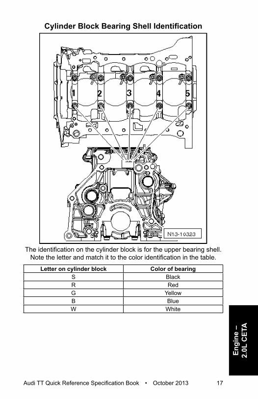
Crankshaft, Cylinder Block – 2.0L CETACylinder Block Bearing Shell Identification
The cylinder block bearing shell identification is located either on the oil pan sealing surface or on the
top (transmission side) of the cylinder block.
Audi TT Quick Reference Specification Book • October 2013 17
Engi
ne –
2.
0L C
ETA
Cylinder Block Bearing Shell Identification
The identification on the cylinder block is for the upper bearing shell. Note the letter and match it to the color identification in the table.
Letter on cylinder block Color of bearingS BlackR RedG YellowB BlueW White

18 Audi TT Quick Reference Specification Book • October 2013
Bearing Cap Bearing Shell Identification
The identification on the crankshaft is for the lower bearing shell. Note the letter and match it to the color identification in the table.
Letter on crankshaft Color of bearingS BlackR RedG YellowB BlueW White

Audi TT Quick Reference Specification Book • October 2013 19
Engi
ne –
2.
0L C
ETA
Fastener Tightening SpecificationsComponent NmA/C compressor 25Accessory bracket 3) 10Connecting rod bolt 1) 45 plus an
additional 90° (¼ turn)
Dual mass flywheel 1) 60 plus an additional 90°
(¼ turn)Pressure relief valve 27Sensor wheel 1) 10 plus an
additional 90° (¼ turn)
Vibration damper 1) 2) 150 plus an additional 90°
(¼ turn)1) Replace fastener(s). 2) Coat the O-ring with oil.3) For bolt tightening clarification, refer to ElsaWeb, Ribbed Belt Drive Overview, items
7 and 10.
Crankshaft DimensionsReconditioning Dimension in mm 1)
Crankshaft bearing pin diameter
Connecting rod bearing pin diameter
Basic dimension 58.00 47.801) The preparation of worn crankshafts is not provided.
Piston Ring End GapsPiston ring dimensions in mm
New Wear limit
Compression ring 0.20 to 0.40 0.80Oil scraping ring 0.25 to 0.50 0.80
Piston Ring ClearancePiston ring dimensions in mm
New Wear limit
1st compression ring 0.06 to 0.09 0.202nd compression ring 0.03 to 0.06 0.15Oil scraping rings Cannot be measured

20 Audi TT Quick Reference Specification Book • October 2013
Piston and Cylinder DimensionsHoning dimension in mm
Piston diameter Cylinder bore diameter
Basic dimension 82.465 1) 82.511) Measurements without graphite coating (thickness = 0.02 mm). The graphite
coating wears off.
Accessory Assembly Bracket Tightening Specifications
Step Component Nm1 Tighten bolts 1 through 5 in sequence Hand-tighten2 Tighten bolts 1 through 5 in sequence 203 Tighten bolts 1 through 5 in sequence an additional
90° (¼ turn)

Audi TT Quick Reference Specification Book • October 2013 21
Engi
ne –
2.
0L C
ETA
Sealing Flange Tightening Specifications
Step Component Nm1 Tighten bolts 1 through 8 in sequence Hand-tighten2 Tighten bolts 1 through 8 in sequence 9

22 Audi TT Quick Reference Specification Book • October 2013
Crankshaft Assembly Tightening Specifications
Step Component Nm1 Tighten bolts 1 through 10 and A in sequence Hand-tighten2 Tighten bolts 1 through 10 in sequence 653 Tighten bolts 1 through 10 in sequence an additional
90° (¼ turn)4 Tighten bolts A 205 Tighten bolts A an additional
90° (¼ turn)

Audi TT Quick Reference Specification Book • October 2013 23
Engi
ne –
2.
0L C
ETA
Cylinder Head, Valvetrain – 2.0L CETAFastener Tightening Specifications
Component Fastener size
Nm
Balance shaft 1) - 9Bearing bracket 1) 2) - 9
M6 8 plus an additional 90°
(¼ turn)M8 20 plus an
additional 90° (¼ turn)
Camshaft adjuster actuator - 5Camshaft Position (CMP) sensor - 9Camshaft timing chain guide rail guide pins - 20Chain tensioner 4) - 9Chain tensioner 3) - 65Control valve - 35Engine lifting eye - 25Guide rail for timing chain, guide bolts 20Heat shield 5) 6) - 9
- 20Mounting plate - 9Oil dipstick guide tube - 9Retaining plate - 9Sealing plugs - 5Tensioning rail for timing chain, guide bolts 20Timing chain tensioning rail guide bolts - 20
1) Replace fastener(s). 2) For bolt tightening clarification, refer to ElsaWeb, Camshaft Timing Chain Overview,
items 5 and 7.3) For bolt tightening clarification, refer to ElsaWeb, Balance Shaft Timing Chain
Overview, item 4.4) For bolt tightening clarification, refer to ElsaWeb, Camshaft Timing Chain Overview,
item 2. 5) For bolt tightening clarification, refer to ElsaWeb, Cylinder Head Overview, items
13, 15 and 16.6) For bolt tightening clarification, refer to ElsaWeb, Cylinder Head Overview with AVS,
items 16, 18 and 19.

24 Audi TT Quick Reference Specification Book • October 2013
Valve Dimensions
Dimension Intake valve Exhaust valveDiameter a mm 33.85 ± 0.10 28.0 ± 0.1Diameter b mm 5.98 ± 0.01 5.96 ± 0.01
c mm 104.0 ± 0.2 101.9 ± 0.2α ∠° 45 45
NOTE: Intake and exhaust valves must not be refaced by grinding. Only lapping is permitted.
Compression PressuresNew Bar positive pressure
Wear limit Bar positive pressure
Difference between cylinders
Bar positive pressure11.0 to 14.0 7.0 Maximum 3.0

Audi TT Quick Reference Specification Book • October 2013 25
Engi
ne –
2.
0L C
ETA
Cylinder Head Removal Specifications (with AVS)
Remove cylinder head bolts (Æ) and 1 through 10 in sequence.
Cylinder Head Removal Specifications (without AVS)
Remove cylinder head bolts (Æ) and 1 through 5 in sequence.

26 Audi TT Quick Reference Specification Book • October 2013
Cylinder Head Tightening Specifications (with AVS)
Step Component Nm1 Tighten bolts 1 through 10 in sequence 402 Tighten bolts 1 through 10 in sequence an additional
90° (¼ turn)3 Tighten bolts 1 through 10 in sequence an additional
90° (¼ turn)4 Tighten bolts (Æ) 85 Tighten bolts (Æ) an additional
90° (¼ turn)

Audi TT Quick Reference Specification Book • October 2013 27
Engi
ne –
2.
0L C
ETA
Cylinder Head Tightening Specifications (without AVS)
Step Component Nm1 Tighten bolts 1 through 5 in sequence 402 Tighten bolts 1 through 5 in sequence an additional
90° (¼ turn)3 Tighten bolts 1 through 5 in sequence an additional
90° (¼ turn)4 Tighten bolts (Æ) 85 Tighten bolts (Æ) an additional
90° (¼ turn)

28 Audi TT Quick Reference Specification Book • October 2013
Cylinder Head Cover Removal Specifications
Loosen cylinder head cover bolts 1 through 6 in sequence.

Audi TT Quick Reference Specification Book • October 2013 29
Engi
ne –
2.
0L C
ETA
Cylinder Head Cover Tightening Specifications
Step Component Nm1 Tighten bolts 1 through 6 in sequence in several
stages 1)Hand-tighten
2 Tighten bolts 1 through 6 in sequence 8
3 Tighten bolts 1 through 6 in sequence an additional 90° (¼ turn)
1) Replace fastener(s).

30 Audi TT Quick Reference Specification Book • October 2013
Crankcase Ventilation Tightening Specification
Step Component Nm1 Tighten bolts 1 through 10 in sequence 11

Audi TT Quick Reference Specification Book • October 2013 31
Engi
ne –
2.
0L C
ETA
Upper Timing Chain Cover Tightening Specification
Step Component Nm1 Tighten bolts 1 through 5 in sequence 9

32 Audi TT Quick Reference Specification Book • October 2013
Lower Timing Chain Cover Tightening Specifications
Step Component Nm1 Tighten bolts 1 through 15 in sequence 82 Tighten bolts 1 through 15 in sequence an additional
45° (⅛ turn)

Audi TT Quick Reference Specification Book • October 2013 33
Engi
ne –
2.
0L C
ETA
Lubrication – 2.0L CETAFastener Tightening Specifications
Component Bolt Size NmChain tensioner - 9Engine oil cooler - 23Oil baffle - 9Oil drain plug 1) - 30Oil level thermal sensor nut - 9Oil pressure regulation valve - 9Oil pressure switch - 20Oil pump
M6 9M8 20
Reduced oil pressure switch - 20Suction line - 9
1) Replace fastener(s).

34 Audi TT Quick Reference Specification Book • October 2013
Upper Oil Pan Tightening Specifications
Step Component Nm1 Tighten bolts 1 through 14 in sequence Hand-tighten2 Tighten bolts 1 through 14 in sequence 153 Tighten bolts 1 through 14 in sequence an additional
90° (¼ turn)

Audi TT Quick Reference Specification Book • October 2013 35
Engi
ne –
2.
0L C
ETA
Oil Pan Tightening Specifications
Step Component Nm1 Tighten bolts 1 through 20 in sequence Hand-tighten2 Tighten bolts 1 through 20 in sequence 83 Tighten bolts 1 through 20 in sequence an additional
45° (⅛ turn)
36 Audi TT Quick Reference Specification Book • October 2013
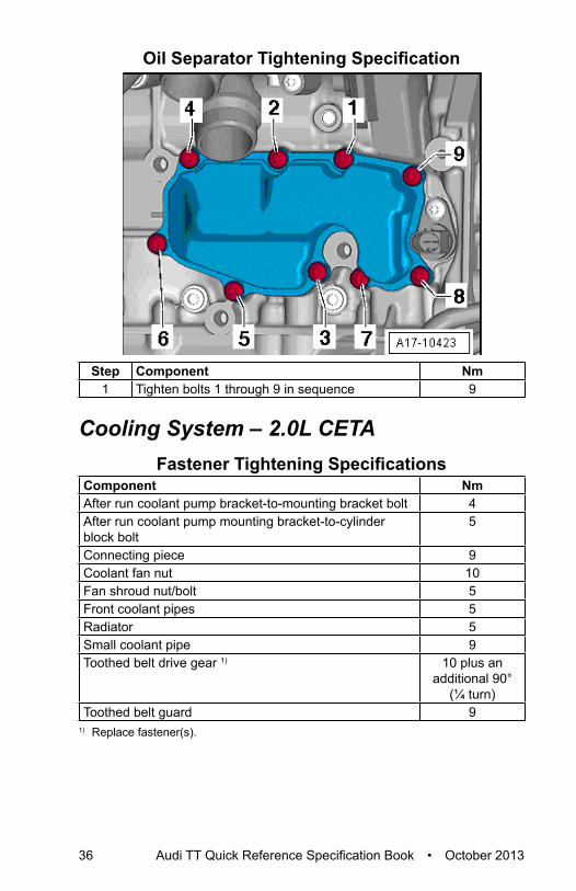
Oil Separator Tightening Specification
Step Component Nm1 Tighten bolts 1 through 9 in sequence 9
Cooling System – 2.0L CETAFastener Tightening Specifications
Component NmAfter run coolant pump bracket-to-mounting bracket bolt 4After run coolant pump mounting bracket-to-cylinder block bolt
5
Connecting piece 9Coolant fan nut 10Fan shroud nut/bolt 5Front coolant pipes 5Radiator 5Small coolant pipe 9Toothed belt drive gear 1) 10 plus an
additional 90° (¼ turn)
Toothed belt guard 91) Replace fastener(s).

Audi TT Quick Reference Specification Book • October 2013 37
Engi
ne –
2.
0L C
ETA
Coolant Pump Tightening Specification
Step Component Nm1 Tighten bolts 1 through 5 in sequence 9

38 Audi TT Quick Reference Specification Book • October 2013
Fuel Supply – 2.0L CETAFastener Tightening Specifications
Component NmAccelerator pedal module-to-body bolt 9Air filter housing-to-bracket bolt 4Bracket-to-body nut 4Evaporative Emission (EVAP) canister to underbody bolt 8Fuel filter bracket bolt 1Leak Detection Pump (LDP) bracket bolt 4Front Wheel Drive (FWD)Fuel tank filler tube-to-underbody bolt 11Fuel tank locking ring 110Fuel tank-to-underbody nut 20Heat shield-to-fuel tank lock washer 3Securing strap-to-underbody nut 20All Wheel Drive (AWD)Fuel tank filler tube-to-underbody bolt 11Fuel tank locking ring 110Heat shield-to-underbody nut 23Securing strap-to-underbody nut 23

Audi TT Quick Reference Specification Book • October 2013 39
Engi
ne –
2.
0L C
ETA
Turbocharger, G-Charger – 2.0L CETAFastener Tightening Specifications
Component NmAir guide pipe-to-bracket 10Charge Air Cooler (CAC) mount 5Charge air pipe 10Charge air pressure sensor 5Connection 9Coolant return line 4)
9
35Coolant supply line 3)
9
35Fastening strip nut 1) 5) 30Oil return line 9Oil supply line 2)
30 5)
9Right air guide pipe-to-oil pan 10Turbocharger bracket 5) 30Turbocharger recirculating valve 7Turbocharger vacuum diaphragm bolt 10Turbocharger vacuum diaphragm nut 6) 9Wastegate bypass regulator valve 3
1) Replace fastener(s). 2) For bolt tightening clarification, refer to ElsaWeb, Turbocharger Overview Part II,
items 2, 5 and 6.3) For bolt tightening clarification, refer to ElsaWeb, Turbocharger Overview Part II,
items 8, 9 and 10.4) For bolt tightening clarification, refer to ElsaWeb, Turbocharger Overview Part III,
items 3 and 6.5) Coat the bolt with hot bolt paste.6) Secure with sealing wax.

40 Audi TT Quick Reference Specification Book • October 2013
Turbocharger Tightening Specifications
Step Component Nm1 Tighten bolts 1 through 5 in sequence 52 Tighten bolts 1 through 5 in sequence 123 Tighten bolts 1 through 5 in sequence 164 Tighten bolts 1 through 5 in sequence 25
Exhaust System – 2.0L CETAFastener Tightening Specifications
Component NmExhaust system bracket nut/bolt 23Front exhaust pipe with catalytic converter and front muffler nut 1) 2)
40
Oxygen Sensors (O2S) 3) 55Suspended mount 23Transverse beam 23
1) Replace fastener(s). 2) Coat turbocharger stud bolts with hot bolt paste.3) Only use hot bolt paste to grease the threads.

Audi TT Quick Reference Specification Book • October 2013 41
Engi
ne –
2.
0L C
ETA
Multiport Fuel Injection – 2.0L CETATechnical Data
Engine data 2.0L Turbo FSI EngineIdle speed cannot be adjusted, it is regulated by idle stabilization
640 to 800 RPM
Engine speed limitation via fuel injector shut-off 6500 RPMFuel pressure Fuel supply-pressure up to
high-pressure pump (is produced by an electric fuel pump in the fuel tank)
3.0 to 7.0 Bar (the same under all operating conditions)
Fuel high pressure (produced by a mechanical single-piston pump) at approximately 85 degree coolant temperature
Approximately 40 Bar positive pressure at idle Approximately 150 Bar positive pressure at certain operating points.
Fastener Tightening SpecificationsComponent NmAir filter upper section 1.5Engine Speed (RPM) sensor 4.5Fuel pressure sensor 27Fuel rail 8Fuel supply line connectors 1) 25Fuel supply line-to-fuel rail connections 1) 25Fuel supply line union nut 20High pressure fuel line 20High pressure pump 20Intake Air Temperature (IAT) sensor 9Intake manifold 9Intake manifold support bolt 20Intake manifold support nut 10Knock Sensor (KS) 1 20Oxygen Sensor (O2S) 55Throttle valve control module 9
1) Replace fastener(s).

42 Audi TT Quick Reference Specification Book • October 2013
Ignition/Glow Plug System – 2.0L CETATechnical Data
Engine data 2.0L Turbo FSI EngineIdle speed cannot be adjusted, it is regulated by idle stabilization
640 to 800 RPM
RPM limited by switching off the fuel injectors and closing the throttle valve.
6500 RPM
Ignition timing is regulated by the control module. It is not possible to adjust the ignition timing.Ignition System Single coil ignition system
with 4 ignition coils (output stages integrated), that are connected directly to the spark plugs via the ignition cables; The ignition coils can be pulled out of the cylinder head using ignition coil puller -T40039-
Ignition sequence 1-3-4-2
Fastener Tightening SpecificationsComponent NmCamshaft position sensor 10Knock sensor 20Spark plug 30

Audi TT Quick Reference Specification Book • October 2013 43
Engi
ne –
2.
0L C
DM
A
ENGINE MECHANICAL – 2.0L CDMAGeneral, Technical Data
Engine Number Location
The engine number (engine code and serial number) (Æ) is located where the engine/transmission are joined.
44 Audi TT Quick Reference Specification Book • October 2013
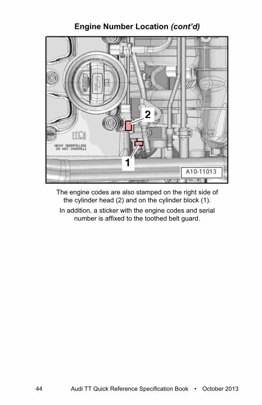
Engine Number Location (cont’d)
The engine codes are also stamped on the right side of the cylinder head (2) and on the cylinder block (1).
In addition, a sticker with the engine codes and serial number is affixed to the toothed belt guard.

Audi TT Quick Reference Specification Book • October 2013 45
Engi
ne –
2.
0L C
DM
A
Engine DataIdentification codes CDMADisplacement liter 1.984Output kW at RPM 195 @ 6000Torque Nm at RPM 350 @ 2500 to 5250Bore diameter mm 82.5Stroke mm 92.8Compression ratio 9.8RON at least 98 1)
Ignition sequence 1-3-4-2Emissions values EU4Exhaust Gas Recirculation (EGR) NoTurbocharger TurbochargerKnock control YesCharge Air Cooler (CAC) YesOxygen Sensor (O2S) regulation 2 sensorsVariable valve timing IntakeVariable intake manifold NoSecondary Air Injection (AIR) system NoValve per cylinder 4
1) Super unleaded RON 95 is also permitted but performance is reduced.

46 Audi TT Quick Reference Specification Book • October 2013
Engine Assembly – 2.0L CDMAFastener Tightening Specifications
Component Fastener size
Nm
Bolts/nuts M6 10M7 15M8 22
M10 40M12 65
Exceptions:Bracket-to-body - 20 plus an
additional 90° (¼ turn)
Bracket-to-engine mount - 20 plus an additional 90°
(¼ turn)Engine mount-to-body - 40 plus an
additional 90° (¼ turn)
Engine mount-to-engine support - 60 plus an additional 90°
(¼ turn)Engine support-to-engine - 45Ground (GND) wire - 22
1) Replace fastener(s).

Audi TT Quick Reference Specification Book • October 2013 47
Engi
ne –
2.
0L C
DM
A
Crankshaft, Cylinder Block – 2.0L CDMACylinder Block Bearing Shell Identification
The upper bearing shells with the correct thickness are allocated to the cylinder block in the factory. Colored dots on the sides of
the bearing shells identify the bearing shell thickness. The letters marked on the lower sealing surface of the cylinder block identify
which bearing thickness must be installed in which location.
Letter on cylinder block Color of bearingS BlackR RedG Yellow

48 Audi TT Quick Reference Specification Book • October 2013
Bearing Cover Bearing Shell Identification
The bearing shells with correct thickness are allocated to the bearing cap at the factory. Colored dots on the sides
of bearing shells identify bearing shell thickness.The allocation of the bearing shells for the bearing cover is identified by a series of letters on the crankshaft ribbed belt
sprocket flange. The first letter of the row of letters represents bearing 1, the second letter is for bearing 2, and so forth.
Letter on crankshaft Color of bearingR RedG YellowB BlueW White
Audi TT Quick Reference Specification Book • October 2013 49
Engi
ne –
2.
0L C
DM
A
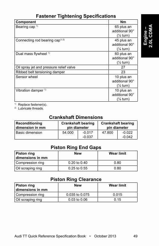
Fastener Tightening SpecificationsComponent NmBearing cap 1) 65 plus an
additional 90° (¼ turn)
Connecting rod bearing cap1) 2) 45 plus an additional 90°
(¼ turn)Dual mass flywheel 1) 60 plus an
additional 90° (¼ turn)
Oil spray jet and pressure relief valve 27Ribbed belt tensioning damper 23Sensor wheel 10 plus an
additional 90° (¼ turn)
Vibration damper 1) 10 plus an additional 90°
(¼ turn)1) Replace fastener(s). 2) Lubricate threads.
Crankshaft DimensionsReconditioning dimension in mm
Crankshaft bearing pin diameter
Crankshaft bearing pin diameter
Basic dimension 54.000 -0.017 -0.037
47.800 -0.022 -0.042
Piston Ring End GapsPiston ring dimensions in mm
New Wear limit
Compression ring 0.20 to 0.40 0.80Oil scraping ring 0.25 to 0.55 0.80
Piston Ring ClearancePiston ring dimensions in mm
New Wear limit
Compression ring 0.035 to 0.075 0.015Oil scraping ring 0.03 to 0.06 0.15
50 Audi TT Quick Reference Specification Book • October 2013
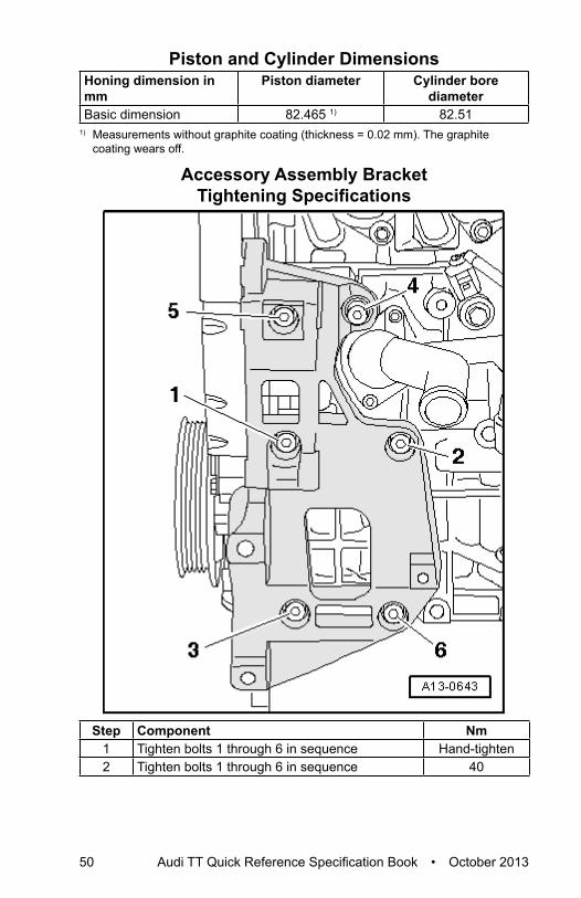
Piston and Cylinder DimensionsHoning dimension in mm
Piston diameter Cylinder bore diameter
Basic dimension 82.465 1) 82.511) Measurements without graphite coating (thickness = 0.02 mm). The graphite
coating wears off.
Accessory Assembly Bracket Tightening Specifications
Step Component Nm1 Tighten bolts 1 through 6 in sequence Hand-tighten2 Tighten bolts 1 through 6 in sequence 40

Audi TT Quick Reference Specification Book • October 2013 51
Engi
ne –
2.
0L C
DM
A
Ribbed Belt Pulley Side Sealing Flange Tightening Specifications
Step Component Nm1 Tighten bolts 1 through 11 in sequence Hand-tighten2 Tighten bolts 1 through 7 in stages and in
sequence 15
3 Tighten bolts 8 through 11 in sequence 15

52 Audi TT Quick Reference Specification Book • October 2013
Ribbed Belt Transmission Side Sealing Flange Tightening Specifications
Step Component Nm1 Tighten bolts 1 through 8 in sequence Hand-tighten2 Tighten bolts 1 through 6 in stages and in
sequence 15
3 Tighten bolts 7 and 8 in sequence 15

Audi TT Quick Reference Specification Book • October 2013 53
Engi
ne –
2.
0L C
DM
A
Cylinder Head, Valvetrain – 2.0L CDMAFastener Tightening Specifications
Component NmCamshaft adjuster 1) 20 plus an
additional 45° (⅛ turn)
Camshaft adjustment valve 1 4Camshaft Position (CMP) sensor 9Camshaft sprocket 1) 50 plus an
additional 180° (½ turn)
Chain tensioner 1) 9Coolant pump 15Crankshaft toothed belt sprocket 1) 90 plus an
additional 90° (¼ turn)
Damper roller 23Drive chain housing 9Engine lifting eye 23Exhaust manifold threaded pin 17Harness mount 9Intake manifold threaded pin 9Lower toothed belt guard 9Pressure regulator valve 4Rear toothed belt guard 2) 9Tensioning roller nut 23Tensioning roller threaded pin 15Toothed belt camshaft gear 1) 50 plus an
additional 180° (½ turn)
Upper toothed belt guard 91) Replace fastener(s). 2) Insert using locking compound, refer to the Electronic Parts Catalog (ETKA).

54 Audi TT Quick Reference Specification Book • October 2013
Valve Dimensions
Dimension Intake valve Exhaust valveDiameter a mm 33.85 ± 0.10 28.0 ± 0.1Diameter
bmm 5.98 ± 0.01 5.96 ± 0.01
c mm 104.0 ± 0.2 101.9 ± 0.2α ∠° 45 45
NOTE: Intake and exhaust valves must not be refaced by grinding. Only lapping is permitted.
Compression PressuresNew Bar positive pressure
Wear limit Bar positive pressure
Difference between cylinders
Bar positive pressure10.0 to 14.0 7.0 Maximum 3.0

Audi TT Quick Reference Specification Book • October 2013 55
Engi
ne –
2.
0L C
DM
A
Cylinder Head Tightening Specifications
Step Component Nm1 Tighten bolts 1 through 10 in sequence 402 Tighten bolts 1 through 10 in sequence an additional
90° (¼ turn)3 Tighten bolts 1 through 10 in sequence an additional
90° (¼ turn)

56 Audi TT Quick Reference Specification Book • October 2013
Cylinder Head Cover Tightening Specifications
Step Component Nm1 Tighten bolts 1 through 14 in sequence Hand-tighten
2 Tighten bolts 1 through 14 in sequence 101) Replace fastener(s).

Audi TT Quick Reference Specification Book • October 2013 57
Engi
ne –
2.
0L C
DM
A
Guide Frame Tightening Specifications
Step Component Nm1 Tighten bolts 1 through 6 in sequence Hand-tighten
2 Tighten bolts 1 through 6 in sequence 8
3 Tighten bolts 1 through 6 in sequence an additional 90° (¼ turn)
1) The guide frame must be in contact with the entire contact surface of the cylinder head.

58 Audi TT Quick Reference Specification Book • October 2013
Lubrication – 2.0L CDMAFastener Tightening Specifications
Component NmChain sprocket 1) 20 plus an
additional 90° (¼ turn)
Chain tensioner with tensioning rail 15Oil baffle 9Oil cooler bracket 15Oil dipstick guide tube double bolt 6Oil drain plug 30Oil filter bracket 15Oil intake pipe 8Oil level thermal sensor 9Oil pressure switch 21Oil pump cover 8Oil return pipe 9
1) Replace fastener(s).
Oil Pan Tightening Specifications
Step Component Nm1 Tighten bolts 1 through 20 in sequence 52 Tighten bolts (Æ) 403 Tighten bolts 1 through 20 in sequence 15

Audi TT Quick Reference Specification Book • October 2013 59
Engi
ne –
2.
0L C
DM
A
Balance Shaft Housing Bolts
Item Component Fastener sizeA Collar bolt M7 x 40B Collar bolt M7 x 70C Collar bolt M7 x 90D Collar bolt M7 x 55E Sealing plug with O-ring

60 Audi TT Quick Reference Specification Book • October 2013
Balance Shaft Housing Tightening Specifications
Step Component Nm1 Tighten bolts (Æ) in a diagonal sequence Hand-tighten
2 Tighten bolts (Æ) in a diagonal sequence 15
3 Tighten bolts (Æ) in a diagonal sequence an additional 90° (¼ turn)
Audi TT Quick Reference Specification Book • October 2013 61
Engi
ne –
2.
0L C
DM
A
Cooling System – 2.0L CDMAFastener Tightening Specifications
Component NmAfter run coolant pump bracket 9After run coolant pump-to-bracket 4Coolant connection 9Coolant fan nut 10Coolant pump 15Coolant thermostat with housing 9Coolant ventilation line 1) 9
2340
Fan rib 5Front coolant pipe 1 9Front coolant pipe 2 9Radiator 5Right front coolant pipe bolt 6Right front coolant pipe nut 9
1) For bolt tightening clarification, refer to ElsaWeb, Coolant Pipes Overview, items 3, 4, and 6.

62 Audi TT Quick Reference Specification Book • October 2013
Fuel Supply – 2.0L CDMAFastener Tightening Specifications
Component NmAccelerator pedal module-to-body bolt 9Air filter housing-to-bracket bolt 4Bracket-to-body nut 4Leak Detection Pump (LDP) bracket bolt 4Evaporative Emission (EVAP) canister-to-underbody bolt 8Fuel filter bracket bolt 1Front Wheel Drive (FWD)Fuel tank filler tube-to-underbody bolt 11Fuel tank locking ring 110Fuel tank-to-underbody nut 20Heat shield-to-fuel tank lock washer 3Securing strap-to-underbody nut 20All Wheel Drive (AWD) Fuel tank filler tube-to-underbody bolt 11Fuel tank locking ring 110Heat shield-to-underbody nut 23Securing strap-to-underbody nut 23
Audi TT Quick Reference Specification Book • October 2013 63
Engi
ne –
2.
0L C
DM
A
Turbocharger, G-Charger – 2.0L CDMAFastener Tightening Specifications
Component NmAir guide pipe nut/bolt 10Bracket-to-turbocharger 5) 6) 30Bracket-to-turbocharger 7) 23Charge Air Cooler (CAC) bearings 5Charge air pressure sensor 5Connection 7Coolant supply pipe bolt 23Coolant supply pipe banjo bolt 35Fastening strip 1) 2) 30Heat shield 9Oil return pipe 3) 9Oil return pipe banjo bolt 4) 35Oil return pipe bolt 4) 9Oil supply pipe banjo bolt 30Oil supply pipe bolt 9Ring connection banjo bolt 8Turbocharger nut 1) 2) 21Turbocharger recirculating valve 7Turbocharger vacuum diaphragm bolts 1) 9Turbocharger vacuum diaphragm lock nut 8) 9Wastegate bypass regulator valve 3
1) Replace fastener(s). 2) Coat the exhaust manifold threaded pins with hot bolt paste.3) For bolt tightening clarification, refer to ElsaWeb, Turbocharger Overview Part II,
items 13, 16 and 18.4) For bolt tightening clarification, refer to ElsaWeb, Turbocharger Overview Part III,
items 3, 5 and 6.5) For bolt tightening clarification, refer to ElsaWeb, Turbocharger Overview Part III,
items 8 and 9.6) Insert with hot bolt paste.7) For bolt tightening clarification, refer to ElsaWeb, Turbocharger Overview Part III,
items 11 and 12.8) Secure with sealing wax after tightening.

64 Audi TT Quick Reference Specification Book • October 2013
Exhaust System – 2.0L CDMAFastener Tightening Specifications
Component NmClamping sleeve nut 23Exhaust door valve bolt/nut 23Exhaust system bracket nut 23Front exhaust pipe with catalytic converter and front muffler 1) 2)
40
Rear muffler bracket bolt/nut 23Suspended mount 23Tunnel brace 23
1) Replace fastener(s). 2) Coat the threaded pin with hot bolt paste.
Fuel Injection and Ignition – 2.0L CDMATechnical Data
Engine data 2.0L Turbo FSI engineIdle speed cannot be adjusted, it is regulated by idle stabilization
640 to 800 RPM
Engine speed limitation via fuel injector shut-off 6500 RPMFuel pressure
Fuel supply-pressure up to high-pressure pump, (is produced by an electric fuel pump in the fuel tank)
Approximately 6.0 Bar positive pressure (same
under all operating conditions)
Fuel high pressure (produced by a mechanical single-piston pump) at approximately 85 degree coolant temperature
Approximately 50 Bar positive pressure at idle Approximately 110 Bar
positive pressure at certain operating points.

Audi TT Quick Reference Specification Book • October 2013 65
Engi
ne –
2.
0L C
DM
A
Fastener Tightening SpecificationsComponent NmAir filter housing bracket bolts 10Air filter housing bolts 5Camshaft Position (CMP) sensor 10Front air guide bolt 2Fuel pressure sensor 20Fuel supply line connection on the fuel rail 27Fuel supply line connectors 30High pressure pump bolts 10Intake Air Temperature (IAT) sensor 5Intake Air Temperature (IAT) sensor 2 5Intake flap motor bolts 7Intake manifold bolts 9Intake manifold support bolt 23Knock Sensor (KS) bolts 20Low fuel pressure sensor 15Mass Air Flow (MAF) sensor 3Oxygen Sensors (O2S) 55Retaining pin 10Spark plug 30Throttle valve control module 7

66 Audi TT Quick Reference Specification Book • October 2013
S TRONIC TRANSMISSION – 02EGeneral, Technical Data
Transmission Identification
The transmission code letters are on top of the transmission near the transmission oil cooler.
Example for above transmission:• GKF = Transmission code• 10.05.2 = Production date May 10th, 2002.
The transmission code is also listed on the vehicle data plate.

S tro
nic
Tran
s. –
02E
Audi TT Quick Reference Specification Book • October 2013 67
Code Letters, Transmission Allocations, Ratios and Equipment
DSG transmission 02E AWDTransmission
Identification codes
KNN KRF
Month of production
from to
06.200810.2008
05.200805.2008
Allocation Model Audi A4 from MY 2007
Audi A4 from MY 2007
Engine
2.0L TFSI 195 kW
2.0L TFSI 195 kW
Gear Ratios Final drive I for 1st to 4th gear
62:13 = 4.769 62:13 = 4.769
Z2: Z1 Final drive IIfor 5th/6th gear
and reverse gear
62:8 = 3.444 62:8 = 3.444
Gear Ratios
1st gear 38:13 = 2.923 38:13 = 2.9232nd gear 45:23 = 1.957 45:23 = 1.9573rd gear 35:25 = 1.400 35:25 = 1.4004th gear 32:31 = 1.032 32:31 = 1.0325th gear 28:26 = 1.077 28:26 = 1.0776th gear 27:31 = 0.871 27:31 = 0.871
Reverse gear 22:14 x 27 13 = 3.264
22:14 x 27 13 = 3.264
i total in highest gear 3.000 3.000Allocation: rear final drive designation
Rear final drive 0AV and 0BR

68 Audi TT Quick Reference Specification Book • October 2013
DSG transmission 02E AWDTransmission
Identification codes
LRK LTY
Month of production
from to
10.200811.2009
11.200906.2010
Allocation Model Audi A4 from MY 2007
Audi A4 from MY 2007
Engine
2.0L TFSI 195 kW
2.0L TFSI 195 kW
Gear Ratios Final drive I for 1st to 4th gear
62:13 = 4.769 62:13 = 4.769
Z2: Z1 Final drive IIfor 5th/6th gear
and reverse gear
62:8 = 3.444 62:8 = 3.444
Gear Ratios
1st gear 38:13 = 2.923 38:13 = 2.9232nd gear 45:23 = 1.957 45:23 = 1.9573rd gear 35:25 = 1.400 35:25 = 1.4004th gear 32:31 = 1.032 32:31 = 1.0325th gear 28:26 = 1.077 28:26 = 1.0776th gear 27:31 = 0.871 27:31 = 0.871
Reverse gear 22:14 x 27 13 = 3.264
22:14 x 27 13 = 3.264
i total in highest gear 3.000 3.000Allocation: rear final drive designation
Rear final drive 0AV and 0BR
Code Letters, Transmission Allocations, Ratios and Equipment (cont’d)

S tro
nic
Tran
s. –
02E
Audi TT Quick Reference Specification Book • October 2013 69
DSG transmission 02E AWDTransmission
Identification codes
MMF MTY
Month of production
from to
05.201011.2010
11.201005.2011
Allocation Model Audi A4 from MY 2007
Audi A4 from MY 2007
Engine
2.0L TFSI 195 kW
2.0L TFSI 155 kW
Gear Ratios Final drive I for 1st to 4th gear
62:13 = 4.769 62:13 = 4.769
Z2: Z1 Final drive IIfor 5th/6th gear
and reverse gear
62:8 = 3.444 62:8 = 3.444
Gear Ratios
1st gear 38:13 = 2.923 38:13 = 2.9232nd gear 45:23 = 1.957 43:24 = 1.7923rd gear 35:25 = 1.400 32:27 = 1.1854th gear 32:31 = 1.032 29:35 = 0.8295th gear 28:26 = 1.077 25:29 = 0.8626th gear 27:31 = 0.871 24:35 = 0.686
Reverse gear 22:14 x 27 13 = 3.264
22:14 x 27 13 = 3.264
i total in highest gear 3.000 3.000Allocation: rear final drive designation
Rear final drive 0AV and 0BR
Code Letters, Transmission Allocations, Ratios and Equipment (cont’d)

70 Audi TT Quick Reference Specification Book • October 2013
DSG transmission 02E AWDTransmission
Identification codes
NJB NJE
Month of production
from to
05.201111.2011
05.201111.2011
Allocation Model Audi A4 from MY 2007
Audi A4 from MY 2007
Engine
2.0L TFSI 155 kW
2.0L TFSI 195 kW
Gear Ratios Final drive I for 1st to 4th gear
62:13 = 4.769 62:13 = 4.769
Z2: Z1 Final drive IIfor 5th/6th gear
and reverse gear
62:8 = 3.444 62:8 = 3.444
Gear Ratios
1st gear 38:13 = 2.923 38:13 = 2.9232nd gear 43:24 = 1.792 45:23 = 1.9573rd gear 32:27 = 1.185 35:25 = 1.4004th gear 29:35 = 0.829 32:31 = 1.0325th gear 25:29 = 0.862 28:26 = 1.0776th gear 24:35 = 0.686 27:31 = 0.871
Reverse gear 22:14 x 27 13 = 3.264
22:14 x 27 13 = 3.264
i total in highest gear 3.000 3.000Allocation: rear final drive designation
Rear final drive 0AV and 0BR
Code Letters, Transmission Allocations, Ratios and Equipment (cont’d)

S tro
nic
Tran
s. –
02E
Audi TT Quick Reference Specification Book • October 2013 71
DSG transmission 02E AWDTransmission
Identification codes
NMA NMB
Month of production
from to
11.201105.2012
11.201105.2012
Allocation Model Audi A4 from MY 2007
Audi A4 from MY 2007
Engine
2.0L TFSI 195 kW
2.0L TFSI 195 kW
Gear Ratios Final drive I for 1st to 4th gear
62:13 = 4.769 62:13 = 4.769
Z2: Z1 Final drive IIfor 5th/6th gear
and reverse gear
62:8 = 3.444 62:8 = 3.444
Gear Ratios
1st gear 38:13 = 2.923 38:13 = 2.9232nd gear 45:23 = 1.957 43:24 = 1.7923rd gear 35:25 = 1.400 32:27 = 1.1854th gear 32:31 = 1.032 29:35 = 0.8295th gear 28:26 = 1.077 25:29 = 0.8626th gear 27:31 = 0.871 24:35 = 0.686
Reverse gear 22:14 x 27 13 = 3.264
22:14 x 27 13 = 3.264
i total in highest gear 3.000 3.000Allocation: rear final drive designation
Rear final drive 0AV and 0BR
Code Letters, Transmission Allocations, Ratios and Equipment (cont’d)
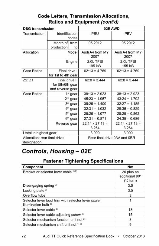
72 Audi TT Quick Reference Specification Book • October 2013
DSG transmission 02E AWDTransmission
Identification codes
PBU PBV
Month of production
from to
05.2012 05.2012
Allocation Model Audi A4 from MY 2007
Audi A4 from MY 2007
Engine
2.0L TFSI 195 kW
2.0L TFSI 155 kW
Gear Ratios Final drive I for 1st to 4th gear
62:13 = 4.769 62:13 = 4.769
Z2: Z1 Final drive IIfor 5th/6th gear
and reverse gear
62:8 = 3.444 62:8 = 3.444
Gear Ratios
1st gear 38:13 = 2.923 38:13 = 2.9232nd gear 45:23 = 1.957 43:24 = 1.7923rd gear 35:25 = 1.400 32:27 = 1.1854th gear 32:31 = 1.032 29:35 = 0.8295th gear 28:26 = 1.077 25:29 = 0.8626th gear 27:31 = 0.871 24:35 = 0.686
Reverse gear 22:14 x 27 13 = 3.264
22:14 x 27 13 = 3.264
i total in highest gear 3.000 3.000Allocation: rear final drive designation
Rear final drive 0AV and 0BR
Controls, Housing – 02EFastener Tightening Specifications
Component NmBracket or selector lever cable 1) 2) 20 plus an
additional 90° (¼ turn)
Disengaging spring 2) 3.5Locking plate 2) 3.5Overflow tube 3Selector lever boot trim with selector lever scale illumination bulb 2)
1
Selector lever cable 2) 13Selector lever cable adjusting screw 3) 15Selector mechanism function unit nut 2) 8Selector mechanism shift unit nut 1) 2) 9
Code Letters, Transmission Allocations, Ratios and Equipment (cont’d)

S tro
nic
Tran
s. –
02E
Audi TT Quick Reference Specification Book • October 2013 73
Component NmSelector mechanism-to-body nut 3) 8Transmission oil filter housing 20Pendulum support 1) 4)
-To transmission 50 plus an additional 90°
(¼ turn)-To subframe 100 plus an
additional 90° (¼ turn)
Transmission fluid check plug 45Transmission fluid drain plug 45Transmission input speed sensor and clutch oil temperature sensor bolt
10
Transmission mount with support arm 1)
-Transmission mount-to-chassis 40 plus an additional 90°
(¼ turn)-Transmission mount-to-transmission support 60 plus an
additional 90° (¼ turn)
Transmission oil cooler 1) 20 plus an additional 45°
(⅛ turn)Transmission oil pump cover 8Transmission support-to-transmission 1) 40 plus an
additional 90° (¼ turn)
1) Replace fastener(s).2) Through 11.2009.3) From 11.2009.4) For bolt tightening clarification, refer to ElsaWeb, Subframe Mount Overview, items
2 and 13.
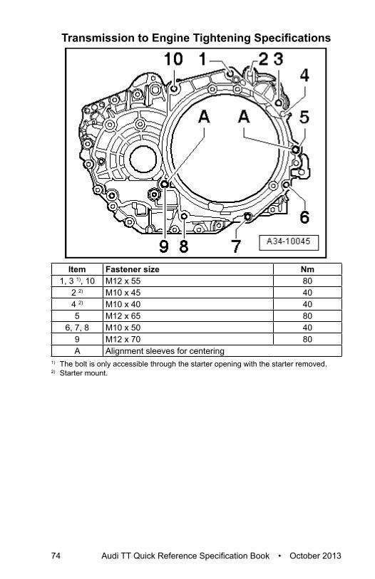
74 Audi TT Quick Reference Specification Book • October 2013
Transmission to Engine Tightening Specifications
Item Fastener size Nm1, 3 1), 10 M12 x 55 80
2 2) M10 x 45 404 2) M10 x 40 405 M12 x 65 80
6, 7, 8 M10 x 50 409 M12 x 70 80A Alignment sleeves for centering
1) The bolt is only accessible through the starter opening with the starter removed.2) Starter mount.

S tro
nic
Tran
s. –
02E
Audi TT Quick Reference Specification Book • October 2013 75
Gears, Shafts – 02EFastener Tightening Specifications
Component NmGuard plate 32Transmission input speed sensor 10Oil pan 1) 16Transmission oil pump- Countersunk bolts 8- Flat head bolts 8 plus an
additional 90° (¼ turn)
Transmission oil pump cover 1) 81) Tighten the bolts diagonally
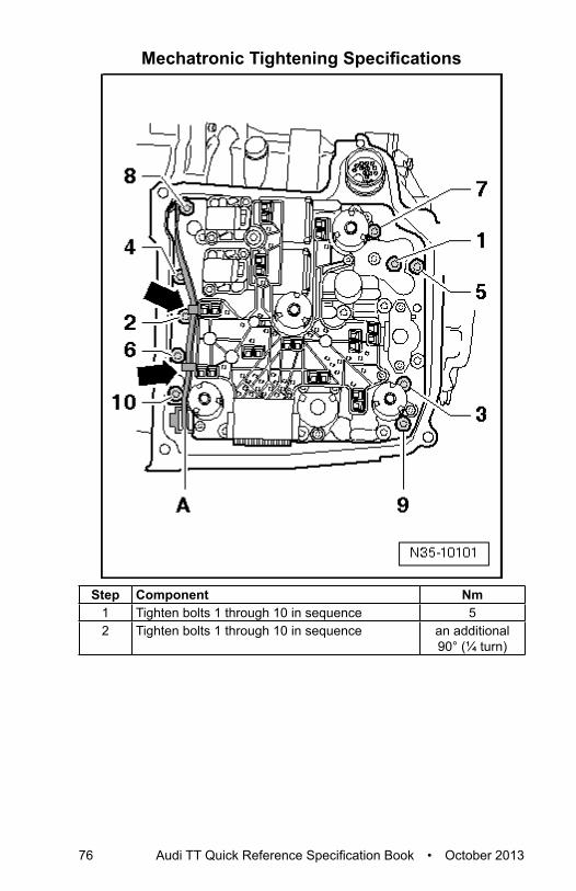
76 Audi TT Quick Reference Specification Book • October 2013
Mechatronic Tightening Specifications
Step Component Nm1 Tighten bolts 1 through 10 in sequence 52 Tighten bolts 1 through 10 in sequence an additional
90° (¼ turn)

S tro
nic
Tran
s. –
02E
Audi TT Quick Reference Specification Book • October 2013 77
Rear Final Drive, Differential – 02EFastener Tightening Specifications
Component NmBevel box output flange 1) 480Bevel box to transmission 1) 40 plus an
additional 90° (⅛ turn)
Drain plug for bevel box oil filler hole 1) 15Gearshift lever, nut 20Left flange shaft 1) 30Oil drain plug for bevel box 60Right drive axle heat shield 25Right flange shaft 1) 30
1) Replace
Bevel Box Bracket for Vehicles with 2.0L TFSI Tightening Specifications
Step Component Nm1 Tighten bolts 1 Hand-tighten2 Tighten bolts 2 403 Tighten bolts 1 40
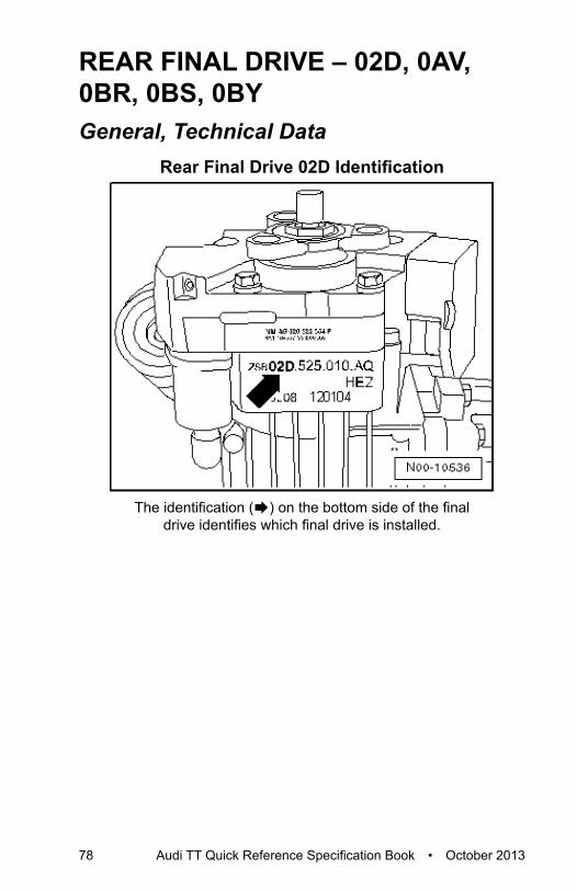
78 Audi TT Quick Reference Specification Book • October 2013
REAR FINAL DRIVE – 02D, 0AV, 0BR, 0BS, 0BYGeneral, Technical Data
Rear Final Drive 02D Identification
The identification (Æ) on the bottom side of the final drive identifies which final drive is installed.

Audi TT Quick Reference Specification Book • October 2013 79
Rea
r Fin
al D
rive
02D
0A
V, 0
BR
, 0B
S, 0
BY
Example of Identifications on A Rear Final Drive “02D”
Rear final drive 0BR or 0BY-Arrow A- final drive part number -Arrow B- final drive code letters -Arrow C- Final drive build date
02D.525.010.AQ HEZ 12 01 04Part Number Code
LettersDay Month Production Year
2004

80 Audi TT Quick Reference Specification Book • October 2013
Rear Final Drive 0AV Identification
If there are no code letters present, then use the part number for the allocation. Refer to the Parts Catalog.
-Arrow A- final drive part number -Arrow B- final drive code letters -Arrow C- Final drive build date
HHJ 09 08 05Code Letters Day Month Production Year 2005

Audi TT Quick Reference Specification Book • October 2013 81
Rea
r Fin
al D
rive
02D
0A
V, 0
BR
, 0B
S, 0
BY
Rear Final Drive 0BR or 0BY Identification
Rear final drive 0BR or 0BYThe identification (Æ) on the bottom side of the final
drive identifies which final drive is installed.

82 Audi TT Quick Reference Specification Book • October 2013
Rear Final Drive 0BS Identification
The identification (Æ) on the bottom side of the final drive identifies which final drive is installed.
Rear Final Drive Transmission Allocations, Ratios, Capacities
Rear Final Drive 0BR with Haldex Clutch Generation IVPart number 0BR.525.010 0BR.525.010.AIdentification codes KMC KMDManufactured from 01.2008 01.2008
through -Allocation Type Audi TT from MY
2007Audi TT from MY
2007Engine 2.0L - 195 kW TFSI 2.0L - 195 kW TFSI
Ratio: Z2: Z1 Rear final drive 27:17 = 1.588 27:17 = 1.588Driveshaft flange diameter (mm) 100 100 Final drive capacity Fluid Capacity Tables; Rep. Gr.03Haldex clutch capacity Fluid Capacity Tables; Rep. Gr.03

Audi TT Quick Reference Specification Book • October 2013 83
Rea
r Fin
al D
rive
02D
0A
V, 0
BR
, 0B
S, 0
BY
Rear Final Drive 0BR with Haldex Clutch Generation IVPart number 0BR.525.010.B 0BR.525.010.CIdentification codes MMK MMLManufactured from 11.2009 10.2009
throughAllocation Type Audi TT from MY
2007Audi TT from MY
2007Engine 2.0L - 155 kW TFSI
2.0L - 195 kW TFSI2.0L - 155 kW TFSI 2.0L - 195 kW TFSI
Ratio: Z2: Z1 Rear final drive 27:17 = 1.588 27:17 = 1.588Driveshaft flange diameter (mm) 100 100 Final drive capacity Fluid Capacity Tables; Rep. Gr.03 Haldex clutch capacity Fluid Capacity Tables; Rep. Gr.03Replacement capacity in Haldex clutch
Fluid Capacity Tables; Rep. Gr.03
Rear Final Drive 0BY With Haldex Clutch Generation IVPart number 0BY.525.010 0BY.525.010.AIdentification codes LEK MBEManufactured from 01.2009 09.2009
throughAllocation Type Audi TT RS from
2007Audi TT RS from
2011Engine 2.5L - 250 kW TFSI 2.5L - 250 kW TFSI
Ratio: Z2: Z1 Rear final drive 27:17 = 1.588 27:17 = 1.588Driveshaft flange diameter (mm) 100 100 Final drive capacity Fluid Capacity Tables; Rep. Gr.03Haldex clutch capacity Fluid Capacity Tables; Rep. Gr.03Replacement capacity in Haldex clutch
Fluid Capacity Tables; Rep. Gr.03
The following information can be found in the Parts Catalog• Rear final drive transmission oil specification• Haldex clutch high performance oil specification• Transmission allocation
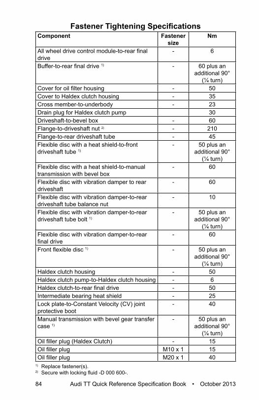
84 Audi TT Quick Reference Specification Book • October 2013
Fastener Tightening SpecificationsComponent Fastener
sizeNm
All wheel drive control module-to-rear final drive
- 6
Buffer-to-rear final drive 1) - 60 plus an additional 90°
(¼ turn)Cover for oil filter housing - 50Cover to Haldex clutch housing - 35Cross member-to-underbody - 23Drain plug for Haldex clutch pump 30Driveshaft-to-bevel box - 60Flange-to-driveshaft nut 2) - 210Flange-to-rear driveshaft tube - 45Flexible disc with a heat shield-to-front driveshaft tube 1)
- 50 plus an additional 90°
(¼ turn)Flexible disc with a heat shield-to-manual transmission with bevel box
- 60
Flexible disc with vibration damper to rear driveshaft
- 60
Flexible disc with vibration damper-to-rear driveshaft tube balance nut
- 10
Flexible disc with vibration damper-to-rear driveshaft tube bolt 1)
- 50 plus an additional 90°
(¼ turn)Flexible disc with vibration damper-to-rear final drive
- 60
Front flexible disc 1) - 50 plus an additional 90°
(¼ turn)Haldex clutch housing - 50Haldex clutch pump-to-Haldex clutch housing - 6Haldex clutch-to-rear final drive - 50Intermediate bearing heat shield - 25Lock plate-to-Constant Velocity (CV) joint protective boot
- 40
Manual transmission with bevel gear transfer case 1)
- 50 plus an additional 90°
(¼ turn)Oil filler plug (Haldex Clutch) - 15Oil filler plug M10 x 1 15Oil filler plug M20 x 1 40
1) Replace fastener(s).2) Secure with locking fluid -D 000 600-.

Audi TT Quick Reference Specification Book • October 2013 85
Rea
r Fin
al D
rive
02D
0A
V, 0
BR
, 0B
S, 0
BY
Pendulum Support First to Transmission Tightening Specifications
Tighten pendulum support first to transmission -arrows B and C- and then to subframe -arrow A-.
Step Component NmPendulum support to Transmission -arrows B and
C-40 plus an
additional 90° (¼ turn)
Subframe -arrow A- 100 plus an additional 90°
(¼ turn)1) Replace fastener(s).

86 Audi TT Quick Reference Specification Book • October 2013
Pendulum Support to Transmission Tightening Specifications
Step Component NmPendulum support to Transmission -1- 40 plus an
additional 90° (¼ turn)
Transmission -2- 40 plus an additional 90°
(¼ turn)1) Replace fastener(s).

Susp
ensi
on,
Whe
els,
Ste
erin
g
Audi TT Quick Reference Specification Book • October 2013 87
SUSPENSION, WHEELS, STEERINGGeneral, Technical data
ChassisFront and All Wheel DriveFront suspension - McPherson struts with lower transverse link
subframe stabilizer bar.Rear suspension - Four-link suspension with separate spring-
shock absorber configuration tubular stabilizer.
Wheelbase mm 2467Front/rear track width 1)
mm 1572/1558
1) Front/rear track width only applicable with 225/55/R16 tires on 7.5Jx16 ET 45 rims.
SteeringFront and All Wheel DriveSteering gear
Electromechanically assisted, maintenance-free rack-and-pinion steering
Maximum steering lock angle on inside wheel
36° 48’
Turning diameter Approximately 10.9 meters
Front SuspensionFastener Tightening Specifications
Component Fastener size
Nm
ABS wheel speed sensor-to-wheel bearing housing bolt
- 8
Ball joint-to-transverse link nut 1) - 40 plus an additional 45°
(⅛ turn)Ball joint-to-wheel bearing housing nut 1) - 20 plus an
additional 90° (¼ turn)
Brake disc-to-wheel hub bolt - 4Coupling rod-to-stabilizer bar nut 1) - 65Coupling rod-to-suspension strut nut 1) - 65Cover plate-to-wheel bearing housing bolt - 10

88 Audi TT Quick Reference Specification Book • October 2013
Component Fastener size
Nm
Drive axle-to-transmission bolt 1) 5) 6) M8 40M10 70
Drive axle to wheel hub bolt 1)
- Hex bolt - 200 plus an additional 180°
(½ turn)- 12-point bolt with ribs - 70 plus an
additional 90° (¼ turn)
- 12-point bolt without ribs - 200 plus an additional 180°
(½ turn)Level control system sensor-to-subframe bolt
- 9
Level control system sensor-to-transverse link nut
- 9
Lower bonded rubber bushing for pendulum support-to-subframe bolt 1) 3)
- 100 plus an additional 90°
(¼ turn)Shock absorber-to-suspension strut bearing nut 1)
- 60
Stabilizer bar-to-subframe bolt 1) - 20 plus an additional 90°
(¼ turn)Subframe-to-body bolt 1) - 70 plus an
additional 90° (¼ turn)
Suspension strut-to-suspension strut dome bolt 1)
- 15 plus an additional 90°
(¼ turn)Suspension strut-to-wheel bearing housing bolt 1) 4)
- 70 plus an additional 90°
(¼ turn)Tie rod end-to-wheel bearing housing nut 1) - 20 plus an
additional 90° (¼ turn)
Transverse link mounting bracket-to-body bolt 1)
- 70 plus an additional 90°
(¼ turn)Transverse link mounting bracket-to-subframe bolt 1)
- 50 plus an additional 90°
(¼ turn)
Fastener Tightening Specifications (cont’d)

Susp
ensi
on,
Whe
els,
Ste
erin
g
Audi TT Quick Reference Specification Book • October 2013 89
Component Fastener size
Nm
Transverse link-to-subframe bolt 1) 2) - 70 plus an additional 180°
(½ turn)Wheel hub-to-wheel bearing housing bolt 1) - 70 plus an
additional 90° (¼ turn)
1) Replace fastener(s).
2) Tighten in the curb weight position.3) Only tighten when pendulum support is bolted to transmission.4) Bolt point must face in direction of travel.5) Pre-tighten diagonally to 10 Nm.6) Tighten diagonally.
Rear SuspensionFastener Tightening Specifications
Component Fastener size
Nm
Brake disc-to-wheel hub bolt - 4Coupling rod-to-stabilizer bar nut - 40Coupling rod-to-wheel bearing housing nut - 25Cover plate-to-wheel bearing housing bolt - 10Cross member brace bolt (Roadster, AWD) - 40Cross member -to-subframe nut (Coupe, AWD)
- 50 plus an additional 180°
(½ turn)Drive axle-to-rear final drive bolt 1) 3) M8 40
M10 70Drive axle to wheel hub bolt (AWD) 1)
- Hex bolt - 200 plus an additional 180°
(½ turn)- 12-point bolt with ribs - 70 plus an
additional 90° (¼ turn)
- 12-point bolt without ribs - 200 plus an additional 180°
(½ turn)Diagonal brace bolt (Roadster, AWD) 1) - 40 plus an
additional 45° (⅛ turn)

90 Audi TT Quick Reference Specification Book • October 2013
Component Fastener size
Nm
Diagonal brace bolt (Roadster, FWD) 1) - 40 plus an additional 45°
(⅛ turn)- 90 plus an
additional 45° (⅛ turn)
Level control system sensor bolt - 5Lower transverse link-to-subframe nut 1) 2) - 95Lower transverse link-to-wheel bearing housing nut 1) 2)
- 90 plus an additional 90°
(¼ turn)Shock absorber-to-body bolt 1) - 50 plus an
additional 45° (⅛ turn)
Shock absorber-to-shock absorber mounting nut 1)
- 25
Shock absorber-to-wheel bearing housing bolt
- 180
Stabilizer bar-to-body bolt 1) - 25 plus an additional 90°
(¼ turn)Subframe-to-body bolt 1) - 90 plus an
additional 90° (¼ turn)
Tie rod-to-subframe nut 1) 2) - 90 plus an additional 90°
(¼ turn)Tie rod-to-wheel bearing housing bolt 1) 2) - 130 plus an
additional 90° (¼ turn)
Trailing arm mounting bracket-to-body bolt 1)
- 50 plus an additional 45°
(⅛ turn)Trailing arm-to-mounting bracket bolt 1) - 90 plus an
additional 90° (¼ turn)
Trailing arm-to-wheel bearing housing bolt 1)
- 90 plus an additional 45°
(⅛ turn)Upper transverse link-to-subframe nut 1) 2) - 95Upper transverse link-to-wheel bearing housing bolt 1) 2)
- 130 plus an additional 90°
(¼ turn)
Fastener Tightening Specifications (cont’d)

Susp
ensi
on,
Whe
els,
Ste
erin
g
Audi TT Quick Reference Specification Book • October 2013 91
Component Fastener size
Nm
Wheel bearing unit-to-wheel bearing housing bolt 1)
- 70 plus an additional 90°
(¼ turn)Wheel hub-to-wheel bearing housing bolt (FWD) 1)
- 200 plus an additional 180°
(½ turn)Wheel speed sensor-to-wheel bearing housing bolt
- 8
1) Replace fastener(s).2) Tighten in the curb weight or control position.3) Pre-tighten diagonally to 10 Nm.
Wheels, TiresFastener Tightening Specifications
Component NmDecorative trim-to-wheel rim bolt 5Tire pressure monitoring sensor union nut 8Wheel bolt-to-hub 120Wheel electronics-to-metal valve microencapsulated bolt (Beru system)
4
Wheel Alignment DataWheel Alignment Specified Values
Front suspension Standard suspension (1BA)
Sport suspension Audi Magnetic Ride
(AMR) (1BL)Individual toe 5′ ± 5′ 5′ ± 5′Total toe 10′ ± 10′ 10′ ± 10′Camber -41′ ± 30′ -41′ ± 30′Maximum permissible difference between both sides
30’ 30’
Toe differential angle at 20° steering angle 1)
1° 18′ ± 20′ 1° 18′ ± 20′
Maximum steering angle at inner wheel
36° 48’ 36° 48’

92 Audi TT Quick Reference Specification Book • October 2013
Front suspension Sport suspension (1BV/1BD)
Sport suspension Audi Magnetic Ride
(AMR) (1BQ)Individual toe 5′ ± 5′ 5′ ± 5′Total toe 10′ ± 10′ 10′ ± 10′Camber -41′ ± 30′ -41′ ± 30′Maximum permissible difference between both sides
30’ 30’
Toe differential angle at 20° steering angle 1)
1° 20′ ± 20′ 1° 20′ ± 20′
Maximum steering angle at inner wheel
36° 48’ 36° 48’
1) The wheel stop on the outer wheel is reduced by this amount. Depending on the computer manufacturer, the toe-out angle difference can be indicated negatively in the alignment computer.
Rear suspension Standard suspension (1BA)
Sport suspension Audi Magnetic Ride
(AMR) (1BL)Total toe 25′ ± 10′ 25′ ± 10′Individual toe 12.5′ ± 5′ 12.5 ′± 5′Maximum permissible deviation from direction of rotation
10’ 10’
Camber -1° 20′ ± 30′ -1° 20′ ± 30′Maximum permissible difference between both sides
30’ 30’
Rear suspension Sport suspension (1BV/1BD)
Sport suspension Audi Magnetic Ride
(AMR) (1BQ)Total toe 25′ ± 10′ 25′ ± 10′Individual toe 12.5 ′± 5′ 12.5′ ± 5′Maximum permissible deviation from direction of rotation
10’ 10’
Camber -1° 20′ ± 30′ -1° 20′ ± 30′Maximum permissible difference between both sides
30’ 30’
Wheel Alignment Specified Values (cont’d)

Susp
ensi
on,
Whe
els,
Ste
erin
g
Audi TT Quick Reference Specification Book • October 2013 93
SteeringFastener Tightening Specifications
Component NmShield-to-steering gear bolt 6Steering column-to-mounting bracket bolt 20Steering column-to-steering gear bolt 1) 20 plus an
additional 90° (¼ turn)
Steering gear-to-subframe bolt 1) 50 plus an additional 90°
(¼ turn)Steering wheel-to-steering column bolt 1) 50Strut-to-steering column bolt 9Tie rod-to-steering gear 100Tie rod end-to-tie rod nut 50Tie rod end-to-wheel bearing housing nut 1) 20 plus an
additional 90° (¼ turn)
1) Replace fastener(s).

94 Audi TT Quick Reference Specification Book • October 2013
BRAkE SYSTEMGeneral, Technical Data
BrakesBrake SystemDual-circuit brake system with diagonal distribution, Anti-lock Brake System (ABS) with Electronic Brake Distribution (EBD). Depending on equipment and construction, may also be equipped with Electronic Differential Lock (EDL), Anti-Slip Regulation (ASR), Electronic Stability Program (ESP).
Front Wheel Brakes – Technical DataFront wheel brakesProduction Relevant No. (PR. No.) 1LJ 1LL 1LK
Front brake caliper FN3 FN3 FNR-G-57Pistons Diameter
mm54 54 57
Production Relevant No. (PR. No.) 1LJ 1LL 1LKFront brake disc Diameter
mm312 (16”) 312 (16”) 340 (17”)
Brake disc thickness (ventilated)
mm 25 25 30
Brake pad wear limit mm 21 21 28Brake pads Pad thickness, new (not including backing plate)
mm 14 14 14
Brake pad wear limit (not including backing plate)
mm 2 2 2

Bra
ke S
yste
m
Audi TT Quick Reference Specification Book • October 2013 95
Front wheel brakesProduction Relevant No. (PR. No.) 1LM 1LNFront brake caliper FNR-G-57 FNR-G-57Pistons Diameter
mm57 57
Production Relevant No. (PR. No.) 1LK 1LKFront brake disc Diameter
mm340 (17”) 340 (17”)
Brake disc thickness (ventilated)
mm 30 30
Brake pad wear limit mm 28 28Brake pads Pad thickness, new (not including backing plate)
mm 14 14
Brake pad wear limit (not including backing plate)
mm 2 2
TT RS Front Wheel BrakesFront wheel brakesBrakes PR number 1LAFront Brake Caliper Brembo M4Pistons 40/40 mm diameterBrake disc PR number 1LKFront brake disc 370 mmBrake disc thickness, ventilated 32 mmBrake disc wear limit 30 mmBrake pad wear limit (not including backing plate)
2 mm

96 Audi TT Quick Reference Specification Book • October 2013
Wheel Brakes – Technical DataRear wheel brakes (FWD)Production Relevant No. (PR. No.) 2ED 1KZRear brake caliper CII 38HR CII 38HRPistons Diameter
mm38 38
Production Relevant No. (PR. No.) 2ED, 2EE 1KZ, 1KJRear brake disc Diameter
mm286 (16”) 286 (16”)
Brake disc thickness (not ventilated)
mm 12 12
Brake disc thickness (ventilated)
mm - -
Brake disc wear limit mm 9 9Brake pads Pad thickness, new (not including backing plate)
mm 12 12
Brake pad wear limit (not including backing plate)
mm 2 2
Rear wheel brakes, AWDProduction Relevant No. (PR. No.) 1KJ 2EE 2EARear brake caliper CII 41HR CII 41HR CII 41HRPistons Diameter
mm41 41 41
Production Relevant No. (PR. No.) 1KJ,1KZ 2EE,2ED 2EARear brake disc Diameter
mm286 (16”) 286 (16”) 310 (17”)
Brake disc thickness (not ventilated)
mm 12 12 -
Brake disc thickness (ventilated)
mm - - 22
Brake disc wear limit mm 9 9 19Brake pad wear limit (not including backing plate)
mm 2 2 2

Bra
ke S
yste
m
Audi TT Quick Reference Specification Book • October 2013 97
Rear wheel brakes, AWDProduction Relevant No. (PR. No.) 2EF 2EGRear brake caliper CII 41HR CII 41HRPistons Diameter
mm41 41
Production Relevant No. (PR. No.) 2EF 2EGRear brake disc Diameter
mm310 (17”) 310 (17”)
Brake disc thickness (not ventilated)
mm - -
Brake disc thickness, ventilated
mm 22 22
Brake disc wear limit mm 19 19Brake pad wear limit (not including backing plate)
mm 2 2
TT RS Rear Wheel BrakesRear wheel brakesBrakes PR number CII 41 HRPistons 41 mm diameterRear brake disc 370 mm diameterBrake disc thickness, ventilated 22 mmBrake disc wear limit 19 mmBrake pad wear limit (not including backing plate)
2 mm
Anti-lock Brake System (ABS)Fastener Tightening Specifications
Component NmABS control module and ABS hydraulic unit brake lines 14ABS hydraulic unit-to-bracket bolt 8ABS wheel speed sensor bolt 8Brake light switch-to-brake master cylinder bolt 5ESP sensor unit bolt 9

98 Audi TT Quick Reference Specification Book • October 2013
Mechanical ComponentsFastener Tightening Specifications
Component NmBrake disc-to-wheel hub bolt 4Brake hose connection with anti-rotation device-to-caliper bolt (16” FN3)
35
Brake line bracket-to-front brake caliper bolt 15Front brake carrier-to-wheel bearing housing bolt 1) 200Rear brake carrier-to-wheel bearing housing bolt 1) 90 plus an
additional 90° (¼ turn)
Brake line connection to front brake caliper- 17” FNR G57 14- 16” FN3 19Brake line connection to front brake hose- 17” FNR G57 14- 16” FN3 12Brake pedal to mounting bracket nut 25Brake pedal mounting bracket nut 25Cover plate-to-front wheel bearing housing bolt 10Damper-to-front brake caliper bolt 10Front brake caliper guide pin 1) 30Parking brake cable left and right bolt 4Parking brake cable lower right clip nut 12Parking brake lever nut 15Parking brake lever trim bolt 0.7Rear brake caliper bleeder screw 10Rear brake caliper bolt 1) 35Rear brake line and brake hose 14Wear indicator wiring bracket-to-front brake caliper bolt 25Wheel speed sensor bolt 8
1) Replace fastener(s).

Bra
ke S
yste
m
Audi TT Quick Reference Specification Book • October 2013 99
Hydraulic ComponentsHydraulic Tightening Specifications
Component NmBrake booster nut 1) 25Brake hose connection with anti-rotation device to front brake caliper- 16” FN-3 35- 17” FNR-G-57 14Brake line- to brake master cylinder 14- to hydraulic unit 14- to front brake hose 14- to rear brake caliper 14- at rear axle 14- at underbody 14Brake master cylinder-to-brake booster nut 1) 20Front brake caliper bleeder screw (FN3) 10Front brake caliper bleeder valve (FNR-G-57) 15Front brake caliper guide pin 30Rear brake caliper bleeder screw 10Rear brake caliper-to-guide pin bolt 1) 35
1) Replace fastener(s).

100 Audi TT Quick Reference Specification Book • October 2013
BODYAir Gap Body Dimensions
Front Gap Dimensions
Component mmA 4.5 ± 0.5 B 4.5 ± 0.5 C 3.5 ± 0.5 D 3.5 ± 0.5 E 3.5 ± 0.5 F 3.5 ± 0.5

Bod
y
Audi TT Quick Reference Specification Book • October 2013 101
Rear Gap Dimensions
Component mmA 4.0 ± 0.5 B 4.5 ± 0.5 C 3.5 ± 0.5 D 2.0 ± 0.5

102 Audi TT Quick Reference Specification Book • October 2013
Body ExteriorBody Front Tightening Specifications
Component NmBrace for fender to frame bolts 23Bumper bracket to lock carrier bolt 5End plate to frame bolts 11Engine mount brace to bracket bolt (Roadster) 23Engine mount brace to engine mount nut (Roadster) 10Engine mount brace to frame bolt (Roadster) 23Fender to frame bolts 11Impact member to lock carrier bolt 30Lock carrier bolts 1) 6
23Noise insulation frame bolts 30
1) For bolt tightening clarification, refer to ElsaWeb, Lock Carrier with Attachments Assembly Overview, items 4 and 6.
Hood, Lids Tightening SpecificationsComponent NmAll modelsFuel filler door to body bolts 4TTGas-filled strut ball stud 21Hood release lever bracket to hood bolts 12CoupeGas-filled strut ball stud 21Rear lid hinge to hood bolts/nut 21Rear lid lock to rear lid nuts 21Striker to body nuts 21RoadsterGas-filled strut ball stud 21Rear lid hinge bolts/nut 21Rear lid lock to rear lid nuts 21TT RSAnti-theft protection to center hood latch bolt 11Anti-rotation protection to hood bolt 2Brace nut 9Brace to anti-theft protection bolt 11Center hood latch bolt 11Left hood latch mount bolt 10Right hood latch mount bolt 3

Bod
y
Audi TT Quick Reference Specification Book • October 2013 103
Component NmRear lid hinge to hood and body bolt/bolt 34Striker pin with catch to hood nuts 9
Front Doors, Central Locking System Tightening Specifications
Component NmAnti-theft cover to door lock bolt 20Bottom door hinge, lower part bottom door hinge, upper part combination screw
32
Bracket to door bolt 2.5Door lock bolt 20Fuel filler door unlock motor to fender- Bolt 9- Nut 1.5Window regulator to door nut 8Window regulator motor to door nut 3.5
Convertible Top Tightening SpecificationsComponent NmConvertible top to body bolts 36Convertible top control module bolts 6Convertible top frame cover bolt 5Convertible top lock nut 9Emergency operation valve 4End plate cover bolt 15Front cover bolt 2.5Front rail bolt 3Housing cover to convertible top control module bolts 4Hydraulic cylinder bolts 10Hydraulic filler plug 5Left roof guide front trim bolt 2.5Oil reservoir clamp bolt 4Oil reservoir filler screw 5Rear guide hinge bolt 3Rail tensioning strap 1)
- Bolt 1.5- Bolt 2.5Retaining strip to convertible top headliner 2)
- Bolt 2.5- Bolt 3

104 Audi TT Quick Reference Specification Book • October 2013
Component NmRight roof guide rear trim bolt 2.5Water tray bolt 2
1) For bolt tightening clarification, refer to ElsaWeb, Convertible Top Cover, items 3 and 8..
2) For bolt tightening clarification, refer to ElsaWeb, Convertible Top Cover, items 4 and 7.
Bumpers Tightening SpecificationsComponent NmTT FrontBumper- Bolt 5- Nut 6.5Bumper guide piece 1)
- Bolt 1.5- Bolt 2.5Guide piece (left/right) bolt 1.5Impact member 30Lower bumper 2)
- Bolt 1.5- Bolt 2Right guide piece bolt 1.5Spoiler bolt 2TT RearBracket to body nut 4Bumper 3)
- Bolt 15- Bolt 2.5Guide piece bolt 2.5Impact member bolt 23Inner guide piece bolt 2.5Left cover strip bolt 2.5Left inner guide piece bolt 2.5Left outer guide piece bolt 2.5Right cover strip bolt 2.5Right inner guide piece bolt 2.5Right outer guide piece bolt 2.5TT RS FrontImpact member bolt 30Lower part of spoiler bolt 2Upper part of spoiler bolt 2
Convertible Top Tightening Specifications (cont’d)

Bod
y
Audi TT Quick Reference Specification Book • October 2013 105
Component NmTT RS RearBumper spoiler bolt 2Bumper bolt 2.5Left exhaust pipe trim bolt 2Diffuser trim bolt 2Impact member 23Left holder for bumper 2.5
1) For bolt tightening clarification, refer to ElsaWeb, Front Bumper, items 4 and 6.2) For bolt tightening clarification, refer to ElsaWeb, Bumper Guide Place, items 1 and
7.3) For bolt tightening clarification, refer to ElsaWeb, Rear Bumper, items 1 and 5.
Glass, Window Regulators Tightening SpecificationsComponent NmWindow regulator nut 9
Exterior Equipment Tightening SpecificationsComponent NmBulkhead heat shield nut 2Carrier plate to Mirror housing 4- Bolt 1.5- Bolt 6.5Center bearing heat shield bolt 8Center muffler trim bolt/nut 2Center tunnel heat shield bolt/nut 8End muffler heat shield nut 4.5Exterior rearview mirror housing bolt 2License plate bracket bolts 0.9Mirror adjusting unit to Exterior rearview mirror housing 1- Bolt 1.5- Bolt 6.5Mirror base cover bolts 6.5Noise insulation 3- Bolt 2- Bolt 6Radiator grille to front bumper 1Sill panel cover trim bolt 1.5Spoiler base plate bolts- Bolt 3- Nut 2Spoiler center part bolt 7Spoiler motor bolt 2 6Upper part of wheel housing liner bolt 2

106 Audi TT Quick Reference Specification Book • October 2013
Component NmWheel housing liner- Bolt 1.5- Nut 2Wheel spoiler- Bolt 1.5- Nut 2
1) For bolt tightening clarification, refer to ElsaWeb, Exterior Rearview Mirror Overview, items 12 and 13..
2) For bolt tightening clarification, refer to ElsaWeb, Underbody Trim Panels, items 1 and 2.
3) For bolt tightening clarification, refer to ElsaWeb, Mirror Housing, items 6 and 7.
Exterior Equipment Tightening Specifications (cont’d)

Bod
y
Audi TT Quick Reference Specification Book • October 2013 107
Body InteriorInterior Equipment Tightening Specifications
Component NmCenter ConsoleFrontCenter console bracket bolt 3.5Center console side trim bolt 2.5Center console trim bolt 1Climatronic control module bolt 2.5Decorative frame bolt 1Front Center Console bolt 2.5Side trim bracket 3.5RearBlind Cover for AUX socket screw 1.5 3.5 8Bracket boltCenter console bracket nutRear center console- Bolt (Roadster) 2.5- Nut 3.5Cover to left parking brake trim bolt 2.5Upholstery bracket to parking brake lever trim 2.5Storage Compartments and CoversDriver side instrument panel cover bolt 2.5Glove compartment bolt 2.5Glove compartment cover bolt 1.6Lower steering column switch trim bolt 2.5Steering column adjustment handle screw 3Upper steering column switch trim bolt 2.5
Passenger Protection, Airbags, Seat Belts Tightening Specifications
Component NmSeat Belts, CoupeAutomatic belt retractor bolt 45Belt anchor bolt 55Belt guide ring bolt 45Belt latch bolt (front seat)Bucket seat only 22All others, 34Belt latch bolt (rear seat) 55Retainer bolt 4.5Three-point seat belt bolt 45

108 Audi TT Quick Reference Specification Book • October 2013
Component NmSeat Belts, RoadsterBelt anchor bolt 55Belt guide bolt 6Belt latch bolt (front seat)- Bucket seat only 22- All others, 34All VehiclesAirbag unit nut 1) 7Airbag control module nut 9Airbag unit bracket 1) 7Angle bracket to central tube bolt 9Battery positive terminal nut 6Battery interrupt igniter nut 15Child seat anchorages, LATCH and top tether- Backrest frame 16- Bracket to seat pan 12- Retainer to backrest 4Connector on seat occupied recognition control module bolt
2.5
Driver footwell air guide channel bolt 2.5Driver seat position sensor 1.3Driver side knee airbag bolt 9Glove compartment 2)
- Bolt 2.5- Bolt 3Knee bar bolt 2.5Left support 9Lower support nut 9Right support 9Side airbag bolt 10Steering wheel bolt 7Switchable belt load limiter connector bolt 45
Interior Trim Tightening SpecificationsComponent NmArmrest bolt 1.3Center defroster vent bolt 2.5Door trim bolt 2.8Front passenger airbag unit nut 2) 7
Passenger Protection, Airbags, Seat Belts Tightening Specifications (cont’d)

Bod
y
Audi TT Quick Reference Specification Book • October 2013 109
Component NmInstrument cluster bolt 2.5Instrument cluster cover 1)
- Bolt 1- Bolt 2.5Instrument panel bolt 3.5Interior door mechanism bolt 1.3Pull handle bolt 3.3Central Tube Part 1 (Driver Side)Central tube threaded pin 23er side instrument panel cover mounting bracket to left support bolt
9
Instrument panel bracket to central tube- Bolt 9- Nut 20Intermediate plate to left support bolt 9Left center section bracket to central tube bolt 9Left support to central tube bolt 9Lower brace to central tube bolt 7Steering column mounting bracket to central tube bolt 20Upper brace to central tube bolt 20Central Tube Part 2 (Passenger Side)Cable guide to central tube 4.5Centering bracket to central tube bolt 9Central tube threaded pin 23Glove compartment bracket to right support bolt 3.5Instrument panel bracket- Bolt 9- Nut 2) 20Instrument panel support to right center section bracket 3.5Intermediate plate to right support bolt 9Left relay and fuse carrier mounting frame to central tube 4.5Right center section bracket to central tube bolt 9Right support to central tube bolt 9Support for the front passenger airbag unit bolt 9Trim, CoupeBelt extraction panel to rear side trim bolt 1C-pillar trim bolt 3.5Footrest bracket bolt 3.5Footrest cover bolt 2Lower bracket bolt 8Lower rear lid trim to rear lid bolt 1.8Luggage compartment side trim bolt 4

110 Audi TT Quick Reference Specification Book • October 2013
Component NmMount for operating lever bolt 12Sun visor to headliner bolt 3.5Upper rear lid trim to rear lid bolt 1.8Trim, RoadsterBelt extraction panel to rear bulkhead cover 0.6Brace between a-pillar and mounting bracket/steering column
9
Bracket to center storage compartment bolt 4Center storage compartment bolt 2Cover for the steering column universal joint to body bolt 2Footrest bracket bolt 3.5Footrest cover bolt 2Lower center storage compartment bolt 2Mount for operating lever bolt 12Rollover protection bracket to rollover protection trim rear section bolt 2)
3
Rear lid trim to rear lid bolt 1.8Reinforcement, tunnel support 9Storage compartment bolt (left/right) 2Sun visor to windshield frame trim bolt 3.5Wind deflector to body bolt 7Wind deflector support to body bolt 7Windshield frame trim to windshield frame 3)
- Bolt 2- Bolt 3.5
1) For bolt tightening clarification, refer to ElsaWeb, InstrumentPanel Overview items 5 and 26.
2) Replace fastener(s).3) For bolt tightening clarification, refer to ElsaWeb, Windshield Frame Trim Overview,
items 2 and 5.
Seat Frames Tightening SpecificationsComponent NmBucket SeatBackrest frame mount to backrest frame bolt 2) 22Release lever cover (left/right) to backrest frame bolt 2) 2.5Manual Front SeatsCable clip to seat pan bolt 3.5Front backrest to seat pan self-locking bolt 36Front seat to floor bolt 40Lumbar support adjustment switch bolt 0.5Retaining plate to Seat height adjuster
Interior Trim Tightening Specifications (cont’d)
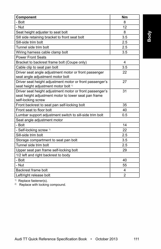
Bod
y
Audi TT Quick Reference Specification Book • October 2013 111
Component Nm- Bolt 8- Nut 12Seat height adjuster to seat bolt 8Sill side retaining bracket to front seat bolt 3.5Sill-side trim bolt 2.5Tunnel side trim bolt 2.5Wiring harness cable clamp bolt 3.5Power Front SeatsBracket to backrest frame bolt (Coupe only) 4Cable clip to seat pan bolt 3.5Driver seat angle adjustment motor or front passenger seat angle adjustment motor bolt
22
Driver seat height adjustment motor or front passenger’s seat height adjustment motor bolt 1)
27
Driver seat height adjustment motor or front passenger’s seat height adjustment motor to lower seat pan frame self-locking screw
31
Front backrest to seat pan self-locking bolt 35Front seat to floor bolt 40Lumbar support adjustment switch to sill-side trim bolt 0.5Seat angle adjustment motor- Bolt 14- Self-locking screw 1) 22Sill-side trim bolt 2.5Storage compartment to seat pan bolt 3.5Tunnel side trim bolt 2.5Upper seat pan frame self-locking bolt 291/2 left and right backrest to body- Bolt 40- Nut 55Backrest frame bolt 4Left/right release bolt 2
1) Replace fastener(s).2) Replace with locking compound.

112 Audi TT Quick Reference Specification Book • October 2013
HEATING, VENTILATION & AIR CONDITIONINGGeneral, Technical Data
Refrigerant Oil DistributionComponent Approximate % of total amount of
oil in componentA/C compressor 50Condenser 10Suction hose 10Evaporator 20Fluid reservoir 10

Heat
ing,
Ven
tilat
ion
&
Air C
ondi
tioni
ng
Audi TT Quick Reference Specification Book • October 2013 113
Refrigerant R134a Vapor Pressure TableTemperature in °C Pressure in Bar
(positive pressure) of R134a-45 -0.61-40 -0.49-35 -0.34-30 -0.16-25 0.06-20 0.32-15 0.63-10 1.00-5 1.430 1.925 2.4910 3.1315 3.9020 4.7025 5.6330 6.7035 7.8340 9.1045 10.5450 12.1155 13.8360 15.7265 17.7970 20.0575 22.5280 25.2185 28.1490 31.34

114 Audi TT Quick Reference Specification Book • October 2013
Air ConditioningFastener Tightening Specifications
Component NmAir intake grille 3.5Compressor drive plateDenso version 1 35Denso version 2 30Compressor mounting bolts 25Coolant pipes-to-heater core 2.5Expansion valve-to-evaporator bracket 10Fluid reservoir on condenser 10High pressure sensor 8Sanden drive plate 25Oil drain plugDenso 30Sanden 10Pressure relief valveDenso 10Sanden 14.5Refrigerant lines-to-compressor 25Refrigerant lines-to-condenser 12Refrigerant lines-to-expansion valve 10
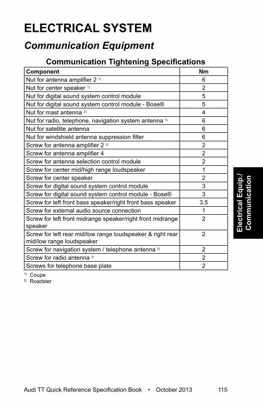
Elec
tric
al E
quip
./ C
omm
unic
atio
n
Audi TT Quick Reference Specification Book • October 2013 115
ELECTRICAL SYSTEMCommunication Equipment
Communication Tightening SpecificationsComponent NmNut for antenna amplifier 2 1) 6Nut for center speaker 1) 2Nut for digital sound system control module 5Nut for digital sound system control module - Bose® 5Nut for mast antenna 2) 4Nut for radio, telephone, navigation system antenna 1) 6Nut for satellite antenna 6Nut for windshield antenna suppression filter 6Screw for antenna amplifier 2 2) 2Screw for antenna amplifier 4 2Screw for antenna selection control module 2Screw for center mid/high range loudspeaker 1Screw for center speaker 2Screw for digital sound system control module 3Screw for digital sound system control module - Bose® 3Screw for left front bass speaker/right front bass speaker 3.5Screw for external audio source connection 1Screw for left front midrange speaker/right front midrange speaker
2
Screw for left rear mid/low range loudspeaker & right rear mid/low range loudspeaker
2
Screw for navigation system / telephone antenna 2) 2Screw for radio antenna 2) 2Screws for telephone base plate 2
1) Coupe2) Roadster

116 Audi TT Quick Reference Specification Book • October 2013
Electrical Equipment Battery, Starter, Generator, Cruise Control Tightening Specifications
Component NmBattery ground cable nut 6Battery jump start terminal nut 5.5Battery jump start pin 9Battery positive cable nut 15Battery retaining bracket nut 20Generator bolts 23Generator terminal 30/B+ 15Main fuse box nut 6Starter ground wire nut 23Starter terminal B+ nut 15Starter wiring harness bracket nut 23
Instruments Tightening SpecificationsComponent NmHorn nut 9Instrument cluster 2.5Radio frequency controlled clock receiver 2.5
Windshield Wiper/Washer Tightening SpecificationsComponent NmHeadlamp washer spray nozzle 2.5Windshield wiper frame bracket nut 6 - 8Wiper arm nut 17

Elec
tric
al E
quip
./ C
omm
unic
atio
n
Audi TT Quick Reference Specification Book • October 2013 117
Windshield Wiper Motor Tightening Sequence
Step Component Nm1 Tighten bolts 1, 2, 4 in sequence Hand-tighten2 Tighten bolts 1, 2, 4 in sequence 8

118 Audi TT Quick Reference Specification Book • October 2013
Exterior Lights, Switches Tightening SpecificationsComponent NmExterior rearview mirror housing-to-base 9.5Exterior rearview mirror mount 2Exterior rearview mirror turn signal bulb 0.4Fog lamp housing 5Headlamp beam adjustment motor 2Headlamp housing bracket screw 4.5Headlamp housing cover 2Headlamp range control module 3License plate lamp 0.8Rear fog lamp 1.2Steering column electronic systems control module 0.4Tail lamp bulb holder 1.7Tail lamp housing 3.5
Interior Lights, Switches Tightening SpecificationComponent NmAlarm horn nut 9
Wiring Tightening SpecificationsComponent NmEngine compartment E-box wire nuts 7.5Left instrument panel fuse panel 3

Elec
tric
al E
quip
./ C
omm
unic
atio
n
Audi TT Quick Reference Specification Book • October 2013 119
Fuse Panel D Tightening Specification
Item Component Nm1 Electrical wire 7.52 Nut 93 Nut 94 Fuse panel D inside the luggage compartment -5 Electrical wire 7.56 Electrical wire 7.57 Bolt 3.58 Electrical wire 159 Battery interrupt igniter (N253) -

120 Audi TT Quick Reference Specification Book • October 2013
DTC CHARTEngine Code – 2.0L CETA
Fuel and Air Mixture, Additional Emission Regulations
DTC Error Message Malfunction Criteria and Threshold Value
P000A “A” Camshaft Position Slow Response Bank 1
• Difference between target position vs. actual position > 8.00° CRK
• For time > 1.30 to 2.90 Sec.and• Adjustment angle ≥ 2.50° CRK
P0010 "A" Camshaft Position Actuator Control Circuit/Open Bank 1
Signal voltage, > 4.70 to 5.40 V
P0011 “A” Camshaft Position - Bank 1 Timing Over-Advanced or System Performance
• Difference between target position vs. actual position > 8.00° CRK
• For time > 1.30 to 2.90 Sec.and• Adjustment angle ≥ 2.50° CRK
P0016 Crankshaft Position - Camshaft Position Correlation Bank 1 Sensor A
• Permissible deviation < -11.01° CRK
or• Permissible deviation > 11.01°
CRKP0030 HO2S Heater Control Circuit
Bank 1 Sensor 1Heater voltage 4.70 to 5.40 V
P0031 HO2S Heater Control Circuit Low Bank 1 Sensor 1
Heater voltage 0.00 to 3.26 V
P0032 HO2S Heater Control Circuit High Bank 1 Sensor 1
Signal current > 5.50 A
P0036 HO2S Heater Control Circuit Bank 1 Sensor 2
Heater voltage, 2.34 to 3.59 V
P0037 HO2S Heater Control Circuit Low Bank 1 Sensor 2
Heater voltage < 2.34 V
P0038 HO2S Heater Control Circuit High Bank 1 Sensor 2
Heater voltage > 3.59 V

Audi TT Quick Reference Specification Book • October 2013 121
DTC
Cha
rt
DTC Error Message Malfunction Criteria and Threshold Value
P0068 MAP/MAF – Throttle Position Correlation
• Plausibility with fuel system load calculation < 50%
• Plausibility with fuel system load calculation > 50%
P0070 Ambient Air Temperature Sensor Circuit “A”
AAT signal short to battery/Open circuit, failure
P0071 Ambient Air Temperature Sensor Circuit “A” Range/Performance
• Difference ECT vs. IAT @ manifold @ engine start (depending on engine-off time) < 24.8 to 39.8 K
and• Difference value IAT @
manifold vs. AAT @ engine start (depending on engine-off time) > 24.8 to 39.8 K
and• Difference AAT vs. ECT at
engine start (depending on engine-off time) > 24.8 to 39.8 K
P0072 Ambient Air Temperature Sensor Circuit “A” Low
AAT signal short to ground, failure
P0087 Fuel Rail/System Pressure - Too Low
• Pressure control activity, > 5.00 MPa
and• Fuel trim activity, 1.05 to 1.50-and• Difference between target
pressure vs. actual pressure > -16.38 MPa
P0088 Fuel Rail/System Pressure - Too High
Fuel rail pressure > 13.9 mPa
P0089 Fuel Pressure Regulator 1 Performance
Actual pressure deviation <100 kPa or >100 kPa
P008A Low Pressure Fuel System Pressure - Too Low
Actual pressure < 0.08 MPa
P008B Low Pressure Fuel System Pressure - Too High
Actual pressure > 0.08 MPa
P0100 Mass or Volume Air Flow Sensor “A” Circuit
MAF sensor signal 0 µs

122 Audi TT Quick Reference Specification Book • October 2013
DTC Error Message Malfunction Criteria and Threshold Value
P0101 Mass or Volume Air Flow Sensor “A” Circuit Range/Performance
• Mass air flow vs lower threshold model < 3 to 197kg/h%
• Mass air flow vs upper threshold > 60 to 890 kg/h
P0102 Mass or Volume Air Flow Sensor “A” Circuit Low
MAF sensor signal, <66 u Sec.
P0103 Mass or Volume Air Flow Sensor “A” Circuit High
MAF sensor signal, >4.5 m Sec.
P0106 Manifold Absolute Pressure/Barometric Pressure Sensor Circuit Range/Performance
Rationality Check Low:• Difference manifold pressure -
lower threshold model < 0.0 kPa
• Model range 0.0 to 190.0 kPaRationality Check High:• Difference manifold pressure
- upper threshold model > 0.0 kPa
• Model range 85.0 to 250.0 kPaRationality Check:• Difference barometric sensor
signal vs. manifold pressure signal at engine start > 9.00 kPa
Adaptation Value Monitoring:• Offset value manifold pressure
for load calculation in driving condition range 2 > 8.00 kPa
Cross Check:• Difference manifold pressure
to average value of all pressure sensors @ start < -6.50 kPa
Cross Check:• Difference manifold pressure
to average value of all pressure sensors @ start > 6.00 kPa
Rationality Check:• Manifold pressure signal:
variation between state 1 and 2 < 1.00 kPa

Audi TT Quick Reference Specification Book • October 2013 123
DTC
Cha
rt
DTC Error Message Malfunction Criteria and Threshold Value
P0107 Manifold Absolute Pressure/Barometric Pressure Sensor Circuit Low
• Short to ground signal voltage < 0.20 V
• Manifold pressure signal < 8.00 kPa
P0108 Manifold Absolute Pressure/Barometric Pressure Sensor Circuit High
Range Check:• Manifold pressure signal
> 300.00 kPaShort to Battery/Open Circuit• Signal voltage > 4.80 V
P0111 Intake Air Temperature Sensor 1 Circuit Range/Performance
• Difference ECT vs. IAT @ manifold at engine start (depending on engine-off time, > 25 to 39.8 K
and• Difference IAT @ maifold
vs. AAT @ engine start (depending on engine-off time), > 25 to 39.8 K
and• Difference AAT vs. ECT at
engine start (depending on engine off time) < 24.8 to 39.8 K
P0112 Intake Air Temperature Sensor 1 Circuit Low
Signal voltage, < 0.16 V
P0113 Intake Air Temperature Sensor 1 Circuit High
Signal voltage, < 4.48 V
P0116 Engine Coolant Temperature Sensor 1 Circuit Range/Performance
Cross Check:• Difference ECT vs. IAT @
manifold at engine start > 24.8 to 39.8K (depending on engine off time)
and• Differeence IAT@ manifold vs.
AAT at engine start < 24.8 to 39.8K (depending on engine off time)
and• Difference AAT vs. ECT at
engine start > 24.8 to 39.8K (depending on engine off time)
P0117 Engine Coolant Temperature Sensor 1 Circuit Low
Engine coolant temperature > 140° C

124 Audi TT Quick Reference Specification Book • October 2013
DTC Error Message Malfunction Criteria and Threshold Value
P0118 Engine Coolant Temperature Sensor 1 Circuit Open
Engine coolant temperature < -40.0° C
P0121 Throttle/Pedal Position Sensor/Switch “A” Circuit Range/Performance
• TPS 1 - TPS 2 > 6.30% and• Actual TPS 1 calculated value
> actual TPS 2 calculated value
or• TPS 1 calculated value
> 9.00%P0122 Throttle/Pedal Position
Sensor/Switch “A” Circuit LowSignal voltage < 0.20 V
P0123 Throttle/Pedal Position Sensor/Switch “A” Circuit High
Signal voltage > 4.81 V
P0130 HO2 Sensor Circuit Bank 1 Sensor 1
O2S ceramic temperature < 640° C
P0131 OHO2 Sensor Circuit Low Voltage Bank 1 Sensor 1
Short to Battery:• Nernst voltage UN, < 1.50 Vor• Adjustment voltage IA,
< 0.30 Vor• Adjustment voltage IP < 0.30 V
P0132 HO2 Sensor Circuit High Voltage Bank 1 Sensor 1
Short to Battery: • Nernst voltage UN,> 4.40 Vor• Adjustment voltage IA,
> 7.00 Vor• Adjustment voltage IP > 7.00 V

Audi TT Quick Reference Specification Book • October 2013 125
DTC
Cha
rt
DTC Error Message Malfunction Criteria and Threshold Value
P0133 HO2 Sensor Circuit Slow Response Bank 1 Sensor 1
Symmetric Fault:• Difference of R2L area ratio vs.
L2R area ratio -0.35 to 0.35-• Max value of both counters
for area ratio R2L and L2R ≥ 5 times
Delayed Time:• Gradient ratio ≥ 0.00-• Lower value of both area ratios
R2L and L2R < 0.20-Transient Time:• Gradient ratio ≥ 0.00-• Gradient ratio <≤ 0.00-• Lower value of both area ratios
R2L and L2R < 0.20or• Lower value of both gradient
ratios R2L and L2R < 0.00-Asymmetric Fault:• Difference of R2L area ratio vs.
L2R area ratio <-0.35, >0.35-• Values of both counters for
area ratio R2L and L2R ≥ 5 times
Delayed Time:• Gradient ratio ≥ 0.00-• Gradient ratio ≤ 0.00-• Lower value of both area ratios
R2L and L2R < 0.35-Transient Time:• Gradient ratio ≥ 0.00-• Gradient ratio ≤ 0.00-• Lower value of both area ratios
R2L and L2R < 0.35-or• Lower value of both area ratios
R2L and L2R < 0.00-

126 Audi TT Quick Reference Specification Book • October 2013
DTC Error Message Malfunction Criteria and Threshold Value
P0135 HO2 Sensor Heater Circuit Bank 1 Sensor 1
Out of range-high• O2S ceramic temperature
< 715° Cand• Heater duty cycle, 100%Rationality check:• Ceramic temperature,
< 715° Cand• Time after O2S heater on 40
SecP0136 O2 Circuit Bank 1, Sensor 2 • Delta voltage one step at
heater switching > 2.00 Vand• Cycles completed ≥ 6
P0137 HO2 Sensor Circuit Low Voltage Bank 1 Sensor 2
• Signal voltage < 0.06 V for time > 3 Sec.
and• Difference of sensor voltage
with load pulse and voltage without load pulse (mean value of 3 measurements) < 0.01 V
P0138 HO2 Sensor Circuit High Voltage Bank 1 Sensor 2
Signal voltage > 1.26 V for > 5 Sec.
P0139 HO2 Sensor Circuit Slow Response Bank 1 Sensor 2
• O2S signal rear during fuel cut off > 160 mV
• O2S signal rear either < 624 or > 624 mV
P013A HO2 Sensor Slow Response - Rich to Lean Bank 1 Sensor 2
• EWMA filtered max differential transient time at fuel cut off ≥ 0.7 Sec
and• Number of checks ≥ 3.00
(initial phase and step function)
P0140 HO2 Sensor Circuit No Activity Detected Bank 1 Sensor 2
• Difference of sensor voltage with load pulse and voltage without load pulse (mean value of 3 measurements) ≥ 2.80 V
• Internal resistance > 40000.0 O
and• Exhaust temperature
> 600.0 °C

Audi TT Quick Reference Specification Book • October 2013 127
DTC
Cha
rt
DTC Error Message Malfunction Criteria and Threshold Value
P0141 HO2 Sensor Heater Circuit Bank 1 Sensor 2
Heater resistance, 792.0 to 4560.0 O
P0171 System Too Lean Bank 1 Adaptive value > 6.0%P0172 System Too Rich Bank 1 Adaptive value < 6-.0%P0190 Fuel Rail Pressure Sensor “A”
CircuitSignal voltage > 4.9 V
P0191 Fuel Rail Pressure Sensor “A” Circuit Range/Performance
Actual pressure > 21.30 MPa
P0192 Fuel Rail Pressure Sensor “A” Circuit Low
Signal voltage < 0.2 V
P0201 Injector Circuit/Open - Cylinder 1
• Signal current < 2.1 A
P0202 Injector Circuit/Open - Cylinder 2
• Signal current < 2.1 A
P0203 Injector Circuit/Open - Cylinder 3
• Signal current < 2.1 A
P0204 Injector Circuit/Open - Cylinder 4
• Signal current < 2.1 A
P0221 Throttle/Pedal Position Sensor/Switch “B” Circuit Range/Performance
• TPS 1 - TPS 2 > 6.30%and• Actual TPS 2 calculated value
> actual TPS 1 calculated value
or• TPS 2 calculated value
> 9.00%P0222 Throttle/Pedal Position
Sensor/Switch “B” Circuit Low Input
Signal voltage < 0.20 V
P0223 Throttle/Pedal Position Sensor/Switch “B” Circuit High Input
Signal voltage > 4.81 V
P0234 Turbocharger/Supercharger “A” Overboost Condition
Difference set value boost pressure vs. actual boost pressure value > 20.0 to 127.50 kPa

128 Audi TT Quick Reference Specification Book • October 2013
DTC Error Message Malfunction Criteria and Threshold Value
P0236 Turbocharger/Supercharger Boost Sensor “A” Circuit Range/Performance
• Difference boost pressure signal vs barometric sensor signal, >26.30 kPa
• Differenceboost pressure signal vs barometric sensor signal, <-16.30 kPa
• Difference pressure in front of throttle to average value of all pressure sensors @ start < -6.00 kPa
• Difference pressure in front of throttle to average value of all pressure sensors @ start > 6.00 kPa
P0237 Turbocharger/Supercharger Boost Sensor “A” Circuit Range/Performance
Signal voltage < 0.20 V
P0238 Turbocharger/Supercharger Boost Sensor “A” Circuit High
Signal voltage > 4.88 V
P0243 Turbocharger/Supercharger Wastegate Solenoid “A”
Signal voltage > 4.4 - 5.60 V
P0245 Turbocharger/Supercharger Wastegate Solenoid “A” Low
Signal voltage < 2.15 - 3.25 V
P0246 Turbocharger/Supercharger Wastegate Solenoid “A” High
Signal current, >2.20 to 4.00 A
P025A Fuel Pump Module “A” Control Circuit/Open
Signal voltage > 4.40 - 5.60 V
P025C Fuel Pump Module “A” Control Circuit Low
Signal voltage < 2.15 - 3.25 V
P025D Fuel Pump Module “A” Control Circuit High
Signal current > 1.10 A
P0261 Cylinder 1 Injector Circuit Low Signal current < 2.10 AP0262 Cylinder 1 Injector Circuit High Signal current > 14.70 AP0264 Cylinder 2 Injector Circuit Low Signal current < 2.10 AP0265 Cylinder 2 Injector Circuit High Signal current > 14.70 AP0267 Cylinder 3 Injector Circuit Low Signal current < 2.10 AP0268 Cylinder 3 Injector Circuit High Signal current > 14.70 AP0270 Cylinder 4 Injector Circuit Low Low side signal current < 2.10 AP0271 Cylinder 4 Injector Circuit High Signal current > 14.70 A

Audi TT Quick Reference Specification Book • October 2013 129
DTC
Cha
rt
DTC Error Message Malfunction Criteria and Threshold Value
P0299 Turbocharger/Supercharger “A” Underboost Condition
Difference set value boost pressure vs actual boost pressure value, > 15 kPa
P2004 Intake Manifold Runner Control Stuck Open Bank 1
• Normal closed position, unable to reach
• Signal voltage < 2.62 or > 4.65 V
or • Normal open position, unable
to reach• Signal voltage, < 0.35 or
> 2.38 VP2008 Intake Manifold Runner
Control Circuit/Open Bank 1Signal voltage 4.70 to 5.40 V
P2009 Intake Manifold Runner Control Circuit Low Bank 1
Signal voltage 0.00 to 3.26 V
P2010 Intake Manifold Runner Control Circuit High Bank 1
Signal current > 2.20 A
P2014 Intake Manifold Runner Position Sensor/Switch Circuit Bank 1
Signal voltage > 4.75 V
P2015 Intake Manifold Runner Position Sensor/Switch Circuit Range/Performance Bank 1
Rationality Check:• Difference between target
position vs. actual position > 25.0%
and• Actual position < 0.0 or > 100%Rationality Check High:• Difference between target
position vs. actual position > 25.0%
and• Actual position < 0.0 or > 100%Rationality Check Low:• Difference between target
position vs. actual position > 25.0%
and• Actual position < 0.0 or > 100%
P2016 Intake Manifold Runner Position Sensor/Switch Circuit Low Bank 1
Signal voltage, < 0.25 V

130 Audi TT Quick Reference Specification Book • October 2013
DTC Error Message Malfunction Criteria and Threshold Value
P2088 “A” Camshaft Position Actuator Control Circuit Low Bank 1
Signal voltage, 0.0 to 3.25 V
P2089 “A” Camshaft Position Actuator Control Circuit High Bank 1
Signal current > 2.20 A
P2096 Post Catalyst Fuel Trim System Too Lean Bank 1
I-portion of 2nd lambda control loop < -0.045
P2097 Post Catalyst Fuel Trim System Too Rich Bank 1
I-portion of 2nd lambda control loop > 0.045
P3081 Engine Temperature Too Low Difference between ECT and modeled ECT > 9.8 K
Ignition SystemDTC Error Message Malfunction Criteria and
Threshold ValueP0300 Random/Multiple Cylinder
Misfire Detected• Emission threshold 1st misfire
rate (MR) > 1.7%• Catalyst damage misfire rate
(MR) > 2.5 - 20.0% P0301 Cylinder 1 Misfire Detected • Emission threshold misfIre rate
(MR) >1.90%• Catalyst damage misfIre rate
(MR) > 3.70 to 16.76% P0302 Cylinder 2 Misfire Detected • Emission threshold misfIre rate
(MR) >1.90%• Catalyst damage misfIre rate
(MR) > 3.70 to 16.76% P0303 Cylinder 3 Misfire Detected • Emission threshold misfIre rate
(MR) >1.90%• Catalyst damage misfIre rate
(MR) > 3.70 to 16.76% P0304 Cylinder 4 Misfire Detected • Emission threshold misfIre rate
(MR) >1.90%• Catalyst damage misfIre rate
(MR) > 3.70 to 16.76% P0321 Ignition/Distributor Engine
Speed Input Circuit Range/Performance
Counted teeth versus reference, incorrect > 1
P0322 Ignition/Distributor Engine Speed Input Circuit No Signal
• Camshaft signals > 3.00and• Engine speed no signal

Audi TT Quick Reference Specification Book • October 2013 131
DTC
Cha
rt
DTC Error Message Malfunction Criteria and Threshold Value
P0324 Knock Control System Error • Signal fault counter (combustion) > 24.00-
or• Signal fault counter (measuring
window) > 2.00-P0327 Knock/Combustion Vibration
Sensor 1 Circuit Low Short to Ground Port B:Short to Ground Port A:• Lower threshold < 70 V Signal Range Check:• Lower threshold, < 0.00 to
3.10VP0328 Knock/Combustion Vibration
Sensor 1 Circuit HighShort to Battery Plus Port B:Short to Battery Plus Port A:• Upper threshold > 1.00 VSignal Range Check:• Upper threshold, > 37.50 to
165.00 VP0332 Knock/Combustion Vibration
Sensor 2 Circuit Low Lower threshold 0.05 - 0.38 V
P0333 Knock/Combustion Vibration Sensor 2 Circuit High
Upper threshold 4.5 - 30.0 V
P0340 Camshaft Position Sensor “A” Circuit
Cam adaptation values out of range• > 20° KW• < -20° KW• Difference of adapted and
actual values > 9° KWP0341 Camshaft Position Sensor “A”
Circuit Range/Performance• Signal pattern incorrectand• Defect counter = 12
P0342 Camshaft Position Sensor “A” Circuit Low
• Signal voltage permanently lowand• Crankshaft signals = 8.0
P0343 Camshaft Position Sensor “A” Circuit High
• Signal voltage permanently high
and• Internal check failed
P0351 Ignition Coil “A” Primary Control Circuit/Open
• Signal current, < 0.25 to -2.00 mA
or• Internal check failed

132 Audi TT Quick Reference Specification Book • October 2013
DTC Error Message Malfunction Criteria and Threshold Value
P0352 Ignition Coil “B” Primary/Secondary Circuit
• Signal current, < 0.25 to -2.00 mA
or• Internal check failed
P0353 Ignition Coil “C” Primary/Secondary Circuit
• Signal current, < 0.25 to -2.00 mA
or• Internal check failed
P0354 Ignition Coil “D” Primary/Secondary Circuit
• Signal current, < 0.25 to -2.00 mA
• Internal check failed
Additional Exhaust RegulationDTC Error Message Malfunction Criteria and
Threshold ValueP0420 Catalyst System Efficiency
Below Threshold Bank 1Amplitude ratio O2S < 1
P0441 EVAP System Incorrect Purge Flow
• Deviation Lambda control < 2.00 to 7.00%
and• Deviation idle controlt
< 30.00%P0442 EVAP System Leak Detected
(small leak)Time for pressure drop < 1.60 to 1.80 Sec.
P0444 EVAP System Purge Control Valve “A” Circuit Open
Signal voltage> 4.70 to 5.40 V
P0455 EVAP System Leak Detected (large leak)
Time for pressure drop < 1.00 Sec.
P0456 EVAP System Leak Detected (very small leak)
Pressure Check:• Time for pressure drop < 5.0 to
6.5 Sec.P0458 EVAP System Purge Control
Valve “A” Circuit LowSignal voltage, 0.00 to 3.26 V
P0459 EVAP System Purge Control Valve "A" Circuit High
Signal current, > 2.20 A

Audi TT Quick Reference Specification Book • October 2013 133
DTC
Cha
rt
Speed and Idle ControlDTC Error Message Malfunction Criteria and
Threshold ValueP0501 Vehicle Speed Sensor “A”
Circuit Range/PerformanceVehicle speed< 2 MPH
P0503 Vehicle Speed Sensor “A” Circuit Intermittent/Erratic/High
Vehicle speed > 200 km/h
P0506 Idle Air Control System RPM Lower Than Expected
• Engine speed deviation > 80.0 RPM
and• RPM controller torque value
≥ calculated max. valueor• Integrated deviation of engine
speed low and integrated deviation of engine speed high > 2000.0 RPM
P0507 le Air Control System RPM Higher Than Expected
• Engine speed deviation > 80 RPM
and• RPM controller torque value
≥ calculated min. valueor• Integrated number of fuel cut
off transitions ≥ n.a.P050A Cold Start Idle Air Control
System PerformancePlausibility Check:• Integrated deviation of engine
speed low and integrated deviation of engine speed high > 2000 RPM
Out of Range Low:• Engine speed deviation
> 80.0 RPMand• RPM controller torque value ≥
calculated max. valueOut of Range High• Engine speed deviation
< -80.0 RPMand• RPM controller torque value ≤
calculated min. valueP050B Cold Start Idle Air Control
System PerformanceDifference between commanded spark timing vs. actual value > 18.00%

134 Audi TT Quick Reference Specification Book • October 2013
DTC Error Message Malfunction Criteria and Threshold Value
P052A Cold Start “A” Camshaft Position Timing Over-Advanced Bank 1
Difference between target position vs. actual position > 6.0° CRK
P053F Cold Start High Fuel Pressure Performance
• Difference between target pressure vs. actual pressure < -1.50 MPa
• Difference between target pressure vs. actual pressure > 1.50 MPa
Control Module and Output SignalsDTC Error Message Malfunction Criteria and
Threshold ValueP0601 Internal Control Module
Memory Check Sum ErrorInternal check sum, incorrect
P0604 Internal Control Module Random Access Memory (RAM) Error
Write ability check, failed
P0605 Internal Control Module Read Only Memory (ROM) Error
Check sum incorrect
P0606 Control Module Processor Module internal check failure.P062B Internal Control Module Fuel
Injector Control PerformanceSPI communications check Identifier failure
P0638 Throttle Actuator Control Range/Performance - Bank 1
Rationality check: • Time to close to reference
point > 0.56 Sec.and• Reference point 2.88%Signal range check: • Duty cycle > 80%and• ECM power stage, no failure• TPS 1 signal voltage < 0.40;
> 0.80 Vor• TPS 2 signal voltage < 4.20;
> 4.60VP0641 Sensor Reference Voltage “A”
Circuit/OpenSignal voltage deviation > +/- 0.30 V
P0642 Sensor Reference Voltage “A” Circuit Low
Signal voltage, < 4.6 to 5 V

Audi TT Quick Reference Specification Book • October 2013 135
DTC
Cha
rt
DTC Error Message Malfunction Criteria and Threshold Value
P0643 Sensor Reference Voltage “A” Circuit High
5 V supply voltage > 5 to 5.4 V
P0651 Sensor Reference Voltage “B” Circuit/Open
Signal voltage deviation > +/- 0.30 V
P0652 Sensor Reference Voltage “B” Circuit Low
Signal voltage, < 4.6-5 V
P0653 Sensor Reference Voltage “B” Circuit High
5 V supply voltage > 5 to 5.4 V
P0657 Actuator Supply Voltage “A” Circuit/Open
Signal voltage, > 4.40 to 5.60 V
P0658 Actuator Supply Voltage “A” Circuit Low
Signal voltage < 2.15 - 3.25 V
P0659 Actuator Supply Voltage “A” Circuit High
Signal current > 1.10 A
P0685 ECM/PCM Power Relay Control Circuit/Open
• Signal voltage 2.6 - 3.7 V• Sense circuit voltage > 6 V
P0686 ECM/PCM Power Relay Control Circuit Low
• Signal voltage 2.6 - 3.7 V• Sense circuit voltage > 6 V
P0687 ECM/PCM Power Relay Control Circuit High
• Signal current > 1.4 - 0.7 A• Sense circuit voltage < 6 V
P0688 ECM/PCM Power Relay Sense Circuit/Open
• Sense voltage < 3.0 V• Sense voltage, > 3.0 V
P0697 Sensor Reference Voltage “C” Circuit/Open
Signal voltage deviation > +/- 0.30 V
P0698 Sensor Reference Voltage “C” Circuit Low
Signal voltage, < 4.6 to 5 V
P0699 Sensor Reference Voltage “C” Circuit High
5 V supply voltage > 5 to 5.4 V
U0001 High Speed CAN Communication Bus
CAN message, no feedback
U0002 High Speed CAN Communication Bus Performance
Global time out-receiving no message
U0100 Lost Communication with ECM/PCM “A”
• Failure of all CAN engine messages, time out > 490 mSec.
• Failure of all CAN engine messages, but not all CAN messages, time out > 1010 mSec.

136 Audi TT Quick Reference Specification Book • October 2013
DTC Error Message Malfunction Criteria and Threshold Value
U0101 Lost Communication with TCM Received CAN message No message
U0121 Lost Communication With Anti-Lock Brake System (ABS) Control Module
Received CAN message no message
U0146 Lost Communication With Gateway “A”
CAN communication with gateway, time-out
U0155 Lost Communication With Instrument Panel Cluster (IPC) Control Module
Received CAN message no message
U0302 Software Incompatibility with Transmission Control Module
TCM signal received AT vehicle data
U0323 CAN: Instrument cluster Audi only
Ambient temperature value module not encoded for ambient temp sensor, 00h
U0402 Invalid Data Received From TCM
Received data implausible message
U0404 Invalid Data Received From Gear Shift Control Module “A”
• If the value of message counter is permanent, constant, or change exceeds a threshold, increment an event counter
• Maximum change of message counter > 5
U0415 Invalid Data Received From Anti-Lock Brake System (ABS) Control Module
• Received data implausible message
• Speed sensor signal 203.0 MPH
• Speed sensor signal 203.0 MPH
• Initialisation error• Vehicle speed 202.00 MPH
U0422 Invalid Data Received From Body Control Module
Ambient temperature value initialization, Audi 01 h
U0423 Invalid Data Received From Instrument Panel Cluster Control Module
• AAT value (initialization) 1.0 h • Received data implausible
messageU0447 Invalid Data Received From
Gateway “A”CAN message incorrect
U102E LIN Communication NLIN message, incorrectU102F LIN Communication Time outU1030 LIN Communication Not active

Audi TT Quick Reference Specification Book • October 2013 137
DTC
Cha
rt
Fuel and Air Ratios Control ModuleDTC Error Message Malfunction Criteria and
Threshold ValueP1114 O2 Sensor Heater Circuit
Bank 1 Sensor 2Heater resistance, (128-648)*(8-40)1.02-25.9 k Ω (dep. on mod. exhaust temperature and heater power)
P12A1 Fuel Rail Pressure Sensor Inappropriately Low
• Pressure control activity, > 0.18 MPa
and• Fuel trim activity < 0.80and• Difference between target
pressure vs. actual pressure -16.38 to 16.38 MPa
P12A2 Fuel Rail Pressure Sensor Inappropriately High
• Pressure control activity, < -0.05 MPa
and• Fuel trim activity ˃ 1.5
P12A4 Fuel Rail Pump Control Valve Stuck Closed
• Pressure control activity, < 6.00 mPa
and• Fuel trim activity, < 0.80-and• Difference between target
pressure vs. actual pressure -16.38 to 16.38 MPa
P13EA Ignition Timing Monitor Difference between commanded spark timing and actual value > 22%
P150A Engine Off Time • Difference between engine off time and ECM after run time < -12.0 Sec.
• Difference between engine off time and ECM after run time > 12.0 Sec.
P2101 Throttle Actuator “A” Control Motor Circuit Range/Performance
• Duty cycle > 80%and• ECM power stage, no failure• Deviation throttle value angles
vs. throttle value setpoint > 4.00 to 50.00%
P2106 Throttle Actuator Control System - Forced Limited Power
Internal check failed

138 Audi TT Quick Reference Specification Book • October 2013
DTC Error Message Malfunction Criteria and Threshold Value
P2110 Throttle Actuator Control System - Forced Limited RPM
Engine load out of range
P2122 Throttle/Pedal Position Sensor/Switch “D” Circuit Low
Signal voltage < 0.61 V
P2123 Throttle/Pedal Position Sensor/Switch “D” Circuit High
Signal voltage > 4.79 V
P2127 Throttle/Pedal Position Sensor/Switch “E” Circuit Low
Signal voltage < 0.27 V
P2128 Throttle/Pedal Position Sensor/Switch “E” Circuit High
Signal voltage > 2.43 V
P2138 Throttle/Pedal Position Sensor/Switch “D”/”E” Voltage Correlation
Signal voltage sensor 1 vs 2, 0.17 to 0.70 V
P2146 Fuel Injector Group “A” Supply Voltage Circuit/Open
• Signal current < 2.6 Aor• Signal current > 14.90 A
P2149 Fuel Injector Group “B” Supply Voltage Circuit/Open
• Signal current < 2.6 Aor• Signal current > 14.90 A
P2177 System Too Lean Off Idle Bank 1
Adaptive value > 26%
P2178 System Too Rich Off Idle Bank 1
Adaptive value < 26%
P2181 Cooling System Performance Cooling system temperature too low after a sufficient mass air flow integral < 74.0 to 84.0° C
P2184 Engine Coolant Temperature Sensor 2 Circuit Low
ECT outlet > 141° C
P2185 ngine Coolant Temperature Sensor 2 Circuit High
ECT outlet < -43° C
P2187 System Too Lean at Idle Bank 1
Adaptive value > 6.00%
P2188 System Too Rich at Idle Bank 1
Adaptive value < 6.0%
P2195 O2 Sensor Signal Biased/Stuck Lean Bank 1 Sensor 1
Delta lambda of 2nd lambda control loop > 0.07-
P2196 O2 Sensor Signal Biased/Stuck Rich - Bank 1, Sensor 1
Delta lambda of 2nd lambda control loop < -0.07-
P2231 O2 Sensor Signal Circuit Shorted to Heater Circuit Bank 1 Sensor 1
Delta O2S signal front > 190 uA
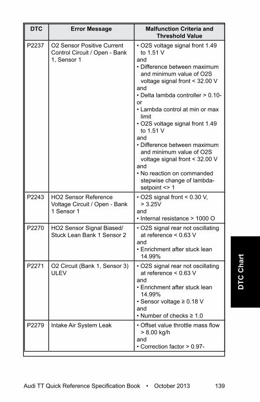
Audi TT Quick Reference Specification Book • October 2013 139
DTC
Cha
rt
DTC Error Message Malfunction Criteria and Threshold Value
P2237 O2 Sensor Positive Current Control Circuit / Open - Bank 1, Sensor 1
• O2S voltage signal front 1.49 to 1.51 V
and• Difference between maximum
and minimum value of O2S voltage signal front < 32.00 V
and• Delta lambda controller > 0.10-or• Lambda control at min or max
limit• O2S voltage signal front 1.49
to 1.51 Vand• Difference between maximum
and minimum value of O2S voltage signal front < 32.00 V
and• No reaction on commanded
stepwise change of lambda-setpoint <> 1
P2243 HO2 Sensor Reference Voltage Circuit / Open - Bank 1 Sensor 1
• O2S signal front < 0.30 V, > 3.25V
and• Internal resistance > 1000 O
P2270 HO2 Sensor Signal Biased/Stuck Lean Bank 1 Sensor 2
• O2S signal rear not oscillating at reference < 0.63 V
and• Enrichment after stuck lean
14.99%P2271 O2 Circuit (Bank 1, Sensor 3)
ULEV• O2S signal rear not oscillating
at reference < 0.63 Vand• Enrichment after stuck lean
14.99%• Sensor voltage ≥ 0.18 Vand• Number of checks ≥ 1.0
P2279 Intake Air System Leak • Offset value throttle mass flow > 8.00 kg/h
and• Correction factor > 0.97-

140 Audi TT Quick Reference Specification Book • October 2013
DTC Error Message Malfunction Criteria and Threshold Value
P2293 Fuel Pressure Regulator 2 Performance
• Difference between target pressure vs. actual pressure, <-2.00 MPa
• Difference between target pressure vs. actual pressure, > 2.00 MPa
P2294 Fuel Pressure Regulator 2 Control Circuit/Open
• Signal voltage 1.40 to 3.20 V
P2295 Fuel Pressure Regulator 2 Control Circuit Low
Signal voltage >1.40 V
P2296 Fuel Pressure Regulator 2 Control Circuit High
Signal voltage > 3.9 V
Ignition SystemDTC Error Message Malfunction Criteria and
Threshold ValueP2300 Ignition Coil “A” Primary
Control Circuit LowSignal current >24.0 mA
P2301 Ignition Coil “A” Primary Control Circuit High
Signal voltage >5.10 to 7.00 V
P2303 Ignition Coil “B” Primary Control Circuit Low
Signal current >24.0 mA
P2304 Ignition Coil “B” Primary Control Circuit High
Signal voltage >5.10 to 7.00 V
P2306 Ignition Coil “C” Primary Control Circuit Low
Signal current >24.0 mA
P2307 Ignition Coil “C” Primary Control Circuit High
Signal voltage >5.10 to 7.00 V
P2309 Ignition Coil “D” Primary Control Circuit Low
Signal current >24.0 mA
P2310 Ignition Coil “D” Primary Control Circuit High
Signal voltage >5.10 to 7.00 V
Additional Emissions RegulationsDTC Error Message Malfunction Criteria and
Threshold ValueP2400 Evaporative Emission System
Leak Detection Pump Control Circuit/Open
Signal voltage > 4.40 to 5.60 V

Audi TT Quick Reference Specification Book • October 2013 141
DTC
Cha
rt
DTC Error Message Malfunction Criteria and Threshold Value
P2401 EVAP System Leak Detection Pump Control Circuit Low
Signal voltage < 2.15 to 3.25 V
P2402 EVAP System Leak Detection Pump Control Circuit High
Signal current > 3.00 A
P2403 EVAP System Leak Detection Pump Sense Circuit/Open
Low signal voltage > 0.50 Sec.
P2404 EVAP System Leak Detection Pump Sense Circuit Range/Performance
• High signal voltage > 12.0 Sec.and• Number of checks 30.00-.• Cumulative time of high signal
voltage during pumping >50.0 Sec.
P2414 O2 Sensor Exhaust Sample Error Bank 1, Sensor 1
Threshold 1:• Signal voltage 3.10 to 4.81VThreshold 2:• Signal voltage 2.50 to 3.10V• Depending on gain factor,
that actual is used for sensor characteristic, the threshold is switched
P2539 Low Pressure Fuel System Sensor Circuit
Signal voltage > 4.9 V
P2540 Low Pressure Fuel System Sensor Circuit Range/Performance
Actual pressure deviation < 800 kPa < 80 kPa
P2541 Low Pressure Fuel System Sensor Circuit Low
Signal voltage < 0.2 V
P2569 Direct Ozone Reduction Catalyst Temperature Sensor Circuit Low
Signal voltage < 0.2 V
P2570 Direct Ozone Reduction Catalyst Temperature Sensor Circuit High
Signal voltage > 5.0 V
P2626 O2 Sensor Pumping Current Trim Circuit/Open Bank 1 Sensor 1
O2S signal front >3.2 V

142 Audi TT Quick Reference Specification Book • October 2013
DTC CHART
Engine Code – 2.0L CDMAFuel and Air Mixture,
Additional Emission RegulationsDTC Error Message Malfunction Criteria and
Threshold ValueP000A “A” Camshaft Position Slow
Response Bank 1• Difference between target
position vs. actual position > 8.00° CRK
• For time > 1.30 to 2.90 Sec.and• Adjustment angle ≥ 2.50° CRK
P0010 “A” Camshaft Position Actuator Control Circuit/Open Bank 1
Signal voltage, > 4.70 to 5.40 V
P0011 “A” Camshaft Position - Bank 1 Timing Over-Advanced or System Performance
• Difference between target position vs. actual position > 8.00° CRK
• For time > 1.30 to 2.90 Sec.and• Adjustment angle < 2.50° CRK
P0016 Crankshaft Position - Camshaft Position Correlation Bank 1 Sensor A
• Permissible deviation < -11.01° CRK
or• Permissible deviation
> 11.01° CRKP0030 HO2S Heater Control Circuit
Bank 1 Sensor 1Heater voltage 4.70 to 5.40 V
P0031 HO2S Heater Control Circuit Low Bank 1 Sensor 1
Heater voltage 0.00 to 3.26 V
P0032 HO2S Heater Control Circuit High Bank 1 Sensor 1
Signal current > 5.50 A
P0036 HO2S Heater Control Circuit Bank 1 Sensor 2
Heater voltage, 2.34 to 3.59 V
P0037 HO2S Heater Control Circuit Low Bank 1 Sensor 2
Heater voltage < 2.34 V
P0038 HO2S Heater Control Circuit High Bank 1 Sensor 2
Heater voltage > 3.59 V

Audi TT Quick Reference Specification Book • October 2013 143
DTC
Cha
rt
DTC Error Message Malfunction Criteria and Threshold Value
P0068 MAP/MAF – Throttle Position Correlation
• Plausibility with fuel system, load calculation <50%
• Plausibility with fuel system, load calculation >50%
P0070 Ambient Air Temperature Sensor Circuit “A”
AAT signal short to battery/Open circuit, failure
P0071 Ambient Air Temperature Sensor Circuit “A” Range/Performance
• Difference ECT vs. IAT @ manifold @ engine start (depending on engine-off time) < 24.8 to 39.8 K
and• Difference value IAT @
manifold vs. AAT @ engine start (depending on engine-off time) > 24.8 to 39.8 K
and• Difference AAT vs. ECT at
engine start (depending on engine-off time) > 24.8 to 39.8 K
P0072 Ambient Air Temperature Sensor Circuit “A” Low
AAT signal short to ground, failure
P0087 Fuel Rail/System Pressure - Too Low
• Pressure control activity, > 5.00 MPaa
and• Fuel trim activity, 1.05 to 1.50-and• Difference between target
pressure vs. actual pressure > -16.38 MPa
P0088 Fuel Rail/System Pressure - Too High
Fuel rail pressure > 13.9 MPa
P0089 Fuel Pressure Regulator 1 Performance
Actual pressure deviation <100 kPa or >100 kPa
P008A Low Pressure Fuel System Pressure - Too Low
Actual pressure < 0.08 MPa
P008B Low Pressure Fuel System Pressure - Too High
Actual pressure > 0.08 MPa
P0100 Mass or Volume Air Flow Sensor “A” Circuit
MAF sensor signal 0 µs

144 Audi TT Quick Reference Specification Book • October 2013
DTC Error Message Malfunction Criteria and Threshold Value
P0101 ass or Volume Air Flow Sensor “A” Circuit Range/Performance
• Mass air flow vs lower threshold model < 3 to 197kg/h%
• Mass air flow vs upper threshold > 60 to 890 kg/h
P0102 Mass or Volume Air Flow Sensor “A” Circuit Low
MAF sensor signal, <66 u Sec.s
P0103 Mass or Volume Air Flow Sensor “A” Circuit High
MAF sensor signal, >4.5 m Sec.
P0106 Manifold Absolute Pressure/Barometric Pressure Sensor Circuit Range/Performance
Rationality Check Low:• Difference manifold pressure -
lower threshold model < 0.0 kPa
• Model range 0.0 to 190.0 kPaRationality Check High:• Difference manifold pressure
- upper threshold model > 0.0 kPa
• Model range 85.0 to 250.0 kPaRationality Check:• Difference barometric sensor
signal vs. manifold pressure signal at engine start > 9.00 kPa
Adaptation Value Monitoring:• Offset value manifold pressure
for load calculation in driving condition range 2 > 8.00 kPa
Adaptation Value Monitoring:• Offset value manifold pressure
for load calculation in driving condition range 2 <- 8.00 kPa
Cross Check:• Diff. manifold pressure to
average value of all pressure sensors @ start < -6.50 kPa
Cross Check:• Diff. manifold pressure to
average value of all pressure sensors @ start > 6.00 kPa
Rationality Check:• Manifold pressure signal:
variation between state 1 and 2 < 1.00 kPa
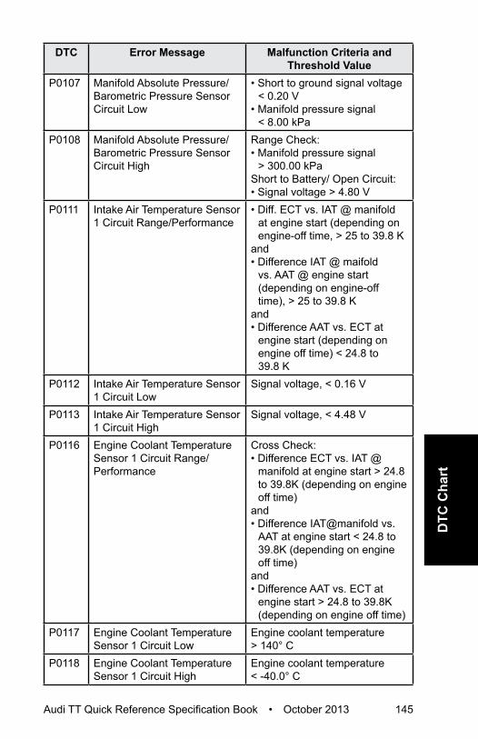
Audi TT Quick Reference Specification Book • October 2013 145
DTC
Cha
rt
DTC Error Message Malfunction Criteria and Threshold Value
P0107 Manifold Absolute Pressure/Barometric Pressure Sensor Circuit Low
• Short to ground signal voltage < 0.20 V
• Manifold pressure signal < 8.00 kPa
P0108 Manifold Absolute Pressure/Barometric Pressure Sensor Circuit High
Range Check:• Manifold pressure signal
> 300.00 kPaShort to Battery/ Open Circuit:• Signal voltage > 4.80 V
P0111 Intake Air Temperature Sensor 1 Circuit Range/Performance
• Diff. ECT vs. IAT @ manifold at engine start (depending on engine-off time, > 25 to 39.8 K
and• Difference IAT @ maifold
vs. AAT @ engine start (depending on engine-off time), > 25 to 39.8 K
and• Difference AAT vs. ECT at
engine start (depending on engine off time) < 24.8 to 39.8 K
P0112 Intake Air Temperature Sensor 1 Circuit Low
Signal voltage, < 0.16 V
P0113 Intake Air Temperature Sensor 1 Circuit High
Signal voltage, < 4.48 V
P0116 Engine Coolant Temperature Sensor 1 Circuit Range/Performance
Cross Check:• Difference ECT vs. IAT @
manifold at engine start > 24.8 to 39.8K (depending on engine off time)
and• Difference IAT@manifold vs.
AAT at engine start < 24.8 to 39.8K (depending on engine off time)
and• Difference AAT vs. ECT at
engine start > 24.8 to 39.8K (depending on engine off time)
P0117 Engine Coolant Temperature Sensor 1 Circuit Low
Engine coolant temperature > 140° C
P0118 Engine Coolant Temperature Sensor 1 Circuit High
Engine coolant temperature < -40.0° C

146 Audi TT Quick Reference Specification Book • October 2013
DTC Error Message Malfunction Criteria and Threshold Value
P0121 Throttle/Pedal Position Sensor/Switch “A” Circuit Range/Performance
• TPS 1 - TPS 2 > 6.30% and• Actual TPS 1 calculated value
> actual TPS 2 calculated value
or• TPS 1 calculated value
> 9.00%P0122 Throttle/Pedal Position
Sensor/Switch “A” Circuit LowSignal voltage, < 0.20 V
P0123 Throttle/Pedal Position Sensor/Switch “A” Circuit High
Signal voltage, > 4.81 V
P0130 HO2 Sensor Circuit Bank 1 Sensor 1
O2S ceramic temperature < 640° C
P0131 HO2 Sensor Circuit Low Voltage Bank 1 Sensor 1
Short to Battery:• Nernst voltage UN, < 1.50 Vor• Adjustment voltage IA,
< 0.30 Vor• Adjustment voltage IP < 0.30 V
P0132 HO2 Sensor Circuit High Voltage Bank 1 Sensor 1
Short to Battery:• Nernst voltage UN, > 4.40 Vor• Adjustment voltage IA,
> 7.00 Vor• Adjustment voltage IP > 7.00 V

Audi TT Quick Reference Specification Book • October 2013 147
DTC
Cha
rt
DTC Error Message Malfunction Criteria and Threshold Value
P0133 HO2 Sensor Circuit Slow Response Bank 1 Sensor 1
Symmetric Fault:\• Difference of R2L area ratio vs.
L2R area ratio -0.35 to 0.35- • Max value of both counters
for area ratio R2L and L2R ≥ 5 times
Delayed Time:• Gradient ratio ≥ 0.00-• Lower value of both area ratios
R2L and L2R < 0.20-Transient Time:• Gradient ratio ≥ 0.00-• Gradient ratio ≤ 0.00-• Lower value of both area ratios
R2L and L2R < 0.20-or• Lower value of both gradient
ratios R2L and L2R < 0.00-Asymmetric Fault:• Difference of R2L area ratio vs.
L2R area ratio <-0.35, >0.35-• Values of both counters for
area ratio R2L and L2R ≥ 5 times
Delay Time:• Gradient ratio ≥ 0.00-• Gradient ratio ≤ 0.00-• Lower value of both area ratios
R2L and L2R < 0.35-Transient Time:• Gradient ratio ≥ 0.00-• Gradient ratio ≤ 0.00-• Lower value of both area ratios
R2L and L2R < 0.35-or• Lower value of both area ratios
R2L and L2R < 0.00-

148 Audi TT Quick Reference Specification Book • October 2013
DTC Error Message Malfunction Criteria and Threshold Value
P0135 O2 Heater Circuit (Bank 1, Sensor 1)
Out of Range-High• O2S ceramic temperature
< 715° Cand• Heater duty cycle 100%Rationality Check:• O2S ceramic temperature
< 715° Cand• Time after O2S heater on 40
Sec.P0136 HO2 Sensor Circuit Bank 1
Sensor 2• Delta voltage one step at
heater switchin >2.0 V• Cycles completed ≥ 6
P0137 HO2 Sensor Circuit Low Voltage Bank 1 Sensor 2
• Signal voltage < 0.06 V for time > 3 Sec.
and• Difference of sensor voltage
with load pulse and voltage without load pulse (mean value of 3 measurements) < 0.01 V
P0138 HO2 Sensor Circuit High Voltage Bank 1 Sensor 2
• Signal voltage >1.26 V• For time > 5.0 Sec
P0139 HO2 Sensor Circuit Slow Response Bank 1 Sensor 2
• O2S signal rear during fuel cut off > 160 mV
• O2S signal rear either < 624 or > 624 mV
P013A HO2 Sensor Slow Response - Rich to Lean Bank 1 Sensor 2
• EWMA filtered max differential transient time at fuel cut off ≥ 0.7 Sec
and• Number of checks ≥ 3.00
(initial phase and step function)
P0140 HO2 Sensor Circuit No Activity Detected Bank 1 Sensor 2
• Difference of sensor voltage with load pulse and voltage without load pulse (mean value of 3 measurements) ≥ 2.80 V
• Internal resistance > 40000.0 O
and• Exhaust temperature
> 600.0° C

Audi TT Quick Reference Specification Book • October 2013 149
DTC
Cha
rt
DTC Error Message Malfunction Criteria and Threshold Value
P0141 HO2 Sensor Heater Circuit Bank 1 Sensor 2
Heater resistance, 792.0 to 4560.0 O
P0171 System Too Lean Bank 1 Adaptive value > 6.0%P0172 System Too Rich Bank 1 Adaptive value < -6.% P0190 Fuel Rail Pressure Sensor “A”
CircuitSignal voltage > 4.8 V
P0191 Fuel Rail Pressure Sensor “A” Circuit Range/Performance
Actual pressure > 21.30 MPa
P0192 Fuel Rail Pressure Sensor “A” Circuit Low
Signal voltage < 0.2 V
P0201 Injector Circuit/Open - Cylinder 1
• Low side signal current < 2.10 A
P0202 Injector Circuit/Open - Cylinder 2
• Low side signal current < 2.10 A
P0203 Injector Circuit/Open - Cylinder 3
• Low side signal current < 2.10 A
P0204 Injector Circuit/Open - Cylinder 4
• Low side signal current < 2.10 A
P0221 Throttle/Pedal Position Sensor/Switch “B” Circuit Range/Performance
• TPS 1 - TPS 2 > 6.30%and• Actual TPS 1 calculated value
> actual TPS 2 calculated value
or• TPS 1 calculated value
> 9.00%P0222 Throttle/Pedal Position
Sensor/Switch “B” Circuit LowSignal voltage < 0.20 V
P0223 Throttle/Pedal Position Sensor/Switch “B” Circuit High
Signal voltage > 4.81 V
P0234 Turbocharger/Supercharger “A” Overboost Condition
Difference set value boost pressure vs. actual boost pressure value > 20.0 to 127.50 kPa

150 Audi TT Quick Reference Specification Book • October 2013
DTC Error Message Malfunction Criteria and Threshold Value
P0236 Turbocharger/Supercharger Boost Sensor “A” Circuit Range/Performance
• Difference boost pressure signal vs barometric sensor signal, >26.30 kPa
• Difference boost pressure signal vs barometric sensor signal, <-16.30 kPa
• Difference pressure in front of throttle to average value of all pressure sensors @ start < -6.00 kPa
• Difference pressure in front of throttle to average value of all pressure sensors @ start > 6.00 kPa
P0237 Turbocharger/Supercharger Boost Sensor “A” Circuit Range/Performance
Signal voltage < 0.2 V
P0238 Turbocharger/Supercharger Boost Sensor “A” Circuit High
Signal voltage, > 4.88 V
P0243 Turbocharger/Supercharger Wastegate Solenoid “A”
Signal voltage, > 4.40 to 5.60 V
P0245 Turbocharger/Supercharger Wastegate Solenoid “A” Low
Signal voltage, < 2.15 to 3.25 V
P0246 Turbocharger/Supercharger Wastegate Solenoid “A” High
Signal current, >2.20 to 4.00 A
P025A Fuel Pump Module “A” Control Circuit/Open
Signal voltage > 4.40 to 5.60 V
P025C Fuel Pump Module “A” Control Circuit Low
Signal voltage< 2.15 to 3.25 V
P025D Fuel Pump Module “A” Control Circuit High
Signal current > 1.10 A
P0261 Cylinder 1 Injector Circuit Low Signal current < 2.10 AP0262 Cylinder 1 Injector Circuit High Signal current > 14.70 AP0264 Cylinder 2 Injector Circuit Low Signal current < 2.10 AP0265 Cylinder 2 Injector Circuit High Signal current > 14.70 AP0267 Cylinder 3 Injector Circuit Low Signal current < 2.10 AP0268 Cylinder 3 Injector Circuit High Signal current > 14.70 AP0270 Cylinder 4 Injector Circuit Low Low side signal current < 2.10 AP0271 Cylinder 4 Injector Circuit High Signal current > 14.70 A

Audi TT Quick Reference Specification Book • October 2013 151
DTC
Cha
rt
DTC Error Message Malfunction Criteria and Threshold Value
P0299 Turbocharger/Supercharger “A” Underboost Condition
Difference set value boost pressure vs actual boost pressure value, > 15 kPa
P2004 Intake Manifold Runner Control Stuck Open Bank 1
• Normal closed position, unable to reach signal voltage < 2.62 or > 4.65 V
or • Normal open position, unable
to reach signal voltage < 0.35 or > 2.38 V
P2008 Intake Manifold Runner Control Circuit/Open Bank 1
Signal voltage 4.70 to 5.40 V
P2009 Intake Manifold Runner Control Circuit Low Bank 1
Signal voltage 0.00 to 3.26 V
P2010 Intake Manifold Runner Control Circuit Shorted to B+ (Bank 1)
Signal current > 2.20 A
P2014 Intake Manifold Runner Position Sensor/Switch Circuit Bank 1
Signal voltage, > 4.75 V
P2015 Intake Manifold Runner Position Sensor/Switch Circuit Range/Performance Bank 1
Rationality Check:• Difference between target
position vs. actual position > 25.0%
and• Actual position < 0.0 or > 100%Rationality Check High:• Difference between target
position vs. actual position > 25.0%%
and• Actual position < 0.0 or > 100%Rationality Check Low:• Difference between target
position vs. actual position > 25.0%
and• Actual position < 0.0 or > 100%
P2016 Intake Manifold Runner Position Sensor/Switch Circuit Low Bank 1
Signal voltage < 0.125 V
P2088 “A” Camshaft Position Actuator Control Circuit Low Bank 1
Signal voltage, 0.0 to 3.25 V
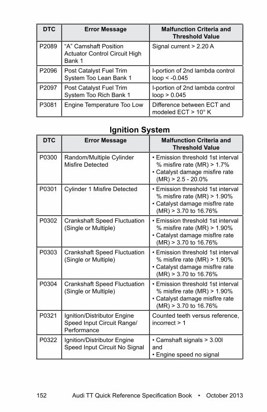
152 Audi TT Quick Reference Specification Book • October 2013
DTC Error Message Malfunction Criteria and Threshold Value
P2089 “A” Camshaft Position Actuator Control Circuit High Bank 1
Signal current > 2.20 A
P2096 Post Catalyst Fuel Trim System Too Lean Bank 1
I-portion of 2nd lambda control loop < -0.045
P2097 Post Catalyst Fuel Trim System Too Rich Bank 1
I-portion of 2nd lambda control loop > 0.045
P3081 Engine Temperature Too Low Difference between ECT and modeled ECT > 10° K
Ignition SystemDTC Error Message Malfunction Criteria and
Threshold ValueP0300 Random/Multiple Cylinder
Misfire Detected• Emission threshold 1st interval
% misfire rate (MR) > 1.7%• Catalyst damage misfire rate
(MR) > 2.5 - 20.0% P0301 Cylinder 1 Misfire Detected • Emission threshold 1st interval
% misfire rate (MR) > 1.90%• Catalyst damage misfIre rate
(MR) > 3.70 to 16.76% P0302 Crankshaft Speed Fluctuation
(Single or Multiple) • Emission threshold 1st interval
% misfire rate (MR) > 1.90%• Catalyst damage misfIre rate
(MR) > 3.70 to 16.76%P0303 Crankshaft Speed Fluctuation
(Single or Multiple) • Emission threshold 1st interval
% misfire rate (MR) > 1.90%• Catalyst damage misfIre rate
(MR) > 3.70 to 16.76%P0304 Crankshaft Speed Fluctuation
(Single or Multiple) • Emission threshold 1st interval
% misfire rate (MR) > 1.90%• Catalyst damage misfIre rate
(MR) > 3.70 to 16.76%P0321 Ignition/Distributor Engine
Speed Input Circuit Range/Performance
Counted teeth versus reference, incorrect > 1
P0322 Ignition/Distributor Engine Speed Input Circuit No Signal
• Camshaft signals > 3.00land• Engine speed no signal

Audi TT Quick Reference Specification Book • October 2013 153
DTC
Cha
rt
DTC Error Message Malfunction Criteria and Threshold Value
P0324 Knock Control System Error • Signal fault counter (combustion) > 24.00-l
or• Signal fault counter (measuring
window) > 2.00-P0327 Knock/Combustion Vibration
Sensor 1 Circuit Low Short to Ground Port B:Short to Ground Port A:• Lower threshold < 0.70 VSignal Range Check:• Lower threshold, < 0.00 to
3.10VP0328 Knock/Combustion Vibration
Sensor 1 Circuit HighShort to Battery Plus Port B:Short to Battery Plus Port A• Upper threshold > 1.00 VSignal Range Check:• Upper threshold, > 37.50 to
165.00 VP0332 Knock/Combustion Vibration
Sensor 2 Circuit Low Lower threshold 0.05 - 0.38 V
P0333 Knock/Combustion Vibration Sensor 2 Circuit High
Upper threshold 4.5 - 30.0 V
P0340 Camshaft Position Sensor “A” Circuit
Cam Adaption Values Out of Range;• > 20° KW• < -20° KW• Difference of adapted and
actual values > 9° KWP0341 Camshaft Position Sensor “A”
Circuit Range/Performance• Signal pattern incorrectand• Defect counter = 12.0
P0342 Camshaft Position Sensor “A” Circuit Low
• Signal voltage permanently lowand• Crankshaft signals = 8.0
P0343 Camshaft Position Sensor “A” Circuit High
• Signal voltage permanently high
and• Crankshaft signals = 8.0
P0351 Ignition Coil “A” Primary Control Circuit/Open
• Signal current, < 0.25 to -2.00 mA
or• Internal check failed

154 Audi TT Quick Reference Specification Book • October 2013
DTC Error Message Malfunction Criteria and Threshold Value
P0352 Ignition Coil “B” Primary Control Circuit/Open
• Signal current, < 0.25 to -2.00 mA
or• Internal check failed
P0353 Ignition Coil “C” Primary Control Circuit/Open
• Signal current, < 0.25 to -2.00 mA
or• Internal check failed
P0354 Ignition Coil “D” Primary Control Circuit/Open
• Signal current, < 0.25 to -2.00 mA
or• Internal check failed
Additional Exhaust RegulationDTC Error Message Malfunction Criteria and
Threshold ValueP0420 Catalyst System Efficiency
Below Threshold Bank 1Amplitude ratio O2S < 1
P0441 EVAP System Incorrect Purge Flow
• Deviation lambda control < 2.00 to 7.00%
and• Deviation idle control < 30.00%
P0442 EVAP System Leak Detected (small leak)
Time for pressure drop < 1.60 to 1.80 Sec.
P0444 EVAP System Purge Control Valve “A” Circuit Open
Signal voltage> 4.70 to 5.40 V
P0455 EVAP System Leak Detected (large leak)
Time for pressure drop < 1.00 Sec.
P0456 EVAP System Leak Detected (very small leak)
Pressure Check:• Time for pressure drop < 5.0 to
6.5 Sec.P0458 EVAP System Purge Control
Valve “A” Circuit LowSignal voltage, 0.00 to 3.26 V
P0459 EVAP System Purge Control Valve “A” Circuit High
Signal current, > 2.20 A

Audi TT Quick Reference Specification Book • October 2013 155
DTC
Cha
rt
Speed and Idle ControlDTC Error Message Malfunction Criteria and
Threshold ValueP0501 Vehicle Speed Sensor “A”
Circuit Range/PerformanceVehicle speed < 2 MPH
P0503 Vehicle Speed Sensor “A” Circuit Intermittent/Erratic/High
Vehicle speed >200.0 km/h
P0506 Idle Air Control System RPM Lower Than Expected
• Engine speed deviation < -80 RPM
and• RPM controller torque value
≥ calculated max. valueor• Integrated deviation of engine
speed low and integrated deviation of engine speed high > 2000.0 RPM
P0507 Idle Air Control System RPM Higher Than Expected
• Engine speed deviation > 80 RPM
and• RPM controller torque value
≥ calculated min. valueor• Integrated number of fuel cut
off transitions ≥ n.a.P050A Cold Start Idle Air Control
System PerformancePlausibilty Check:• Integrated deviation of engine
speed low and integrated deviation of engine speed high > 2000 RPM
Out of Range Low• Engine speed deviation
> 80 RPMand• RPM controller torque value
≥ calculated max. valueOut of Range High• Engine speed deviation
< 80 RPMand• RPM controller torque value
≤ calculated min. valueP050B Cold Start Ignition Timing
PerformanceDifference between commanded spark timing vs. actual value > 18.00%

156 Audi TT Quick Reference Specification Book • October 2013
DTC Error Message Malfunction Criteria and Threshold Value
P052A Cold Start “A” Camshaft Position Timing Over-Advanced Bank 1
Difference between target position and actual position > 6.0° CRK
P053F Cold Start High Fuel Pressure Performance
• Difference between target pressure vs. actual pressure < -1.50 MPa
or• Difference between target
pressure vs. actual pressure > 1.50 MPa
Control Module and Output SignalsDTC Error Message Malfunction Criteria and
Threshold ValueP0601 Internal Control Module
Memory Check Sum ErrorInternal check sum, incorrect
P0604 Internal Control Module Random Access Memory (RAM) Error
Write ability check, failed
P0605 Internal Control Module Read Only Memory (ROM) Error
Checksum incorrect
P0606 Control Module Processor Module internal check failure.P062B Internal Control Module Fuel
Injector Control PerformanceSPI communications check Identifier failure
P0638 Throttle Actuator Control Range/Performance Bank 1
Rationality check:• Time to close to reference
point > 0.56 Sec.and• Reference point 2.88%Signal range check:• Duty cycle > 80%and• ECM power stage, no failure• TPS 1 signal voltage < 0.40;
> 0.80 Vor• TPS 2 signal voltage < 4.20;
> 4.60VP0641 Sensor Reference Voltage “A”
Circuit/OpenSignal voltage deviation > +/- 0.30 V
P0642 Sensor Reference Voltage “A” Circuit Low
Signal voltage, < 4.6 to 5 V

Audi TT Quick Reference Specification Book • October 2013 157
DTC
Cha
rt
DTC Error Message Malfunction Criteria and Threshold Value
P0643 Sensor Reference Voltage “A” Circuit High
5 V supply voltage > 5 to 5.4 V
P0651 Sensor Reference Voltage “B” Circuit/Open
Signal voltage deviation > +/- 0.30 V
P0652 Sensor Reference Voltage “B” Circuit Low
Signal voltage, < 4.6-5 V
P0653 Sensor Reference Voltage “B” Circuit High
5 V supply voltage > 5 to 5.4 V
P0657 Actuator Supply Voltage A Circuit/Open
Signal voltage > 4.4 - 5.6 V
P0658 Actuator Supply Voltage “A” Circuit Low
Signal voltage < 2.15 - 3.25 V
P0659 Actuator Supply Voltage A Circuit High
Signal current > 1.10 A
P0685 ECM/PCM Power Relay Control Circuit/Open
• Signal voltage 2.6 - 3.7 V• Sense circuit voltage < 6 V
P0686 ECM/PCM Power Relay Control Circuit Low
• Signal voltage 2.6 - 3.7 V• Sense circuit voltage > 6 V
P0687 ECM/PCM Power Relay Control Circuit High
• Signal current > 1.4 - 0.7 A• Sense circuit voltage < 6 V
P0688 ECM/PCM Power Relay Sense Circuit
• Sense voltage < 3.0 V• Sense voltage > 3.0 V
P0697 Sensor Reference Voltage “C” Circuit/Open
Signal voltage deviation > +/- 0.30 V
P0698 Sensor Reference Voltage “C” Circuit Low
Signal voltage < 4.6 - 5.0 V
P0699 Sensor Reference Voltage “C” Circuit High
5V supply voltage > 5.0 - 5.4 V
U0001 High Speed CAN Communication Bus
CAN message, no feedback
U0002 High Speed CAN Communication Bus Performance
Global time out-receiving no message
U0100 Lost Communication With ECM/PCM “A”
• Failure of all CAN engine messages, time out more than > 490 mSec.
• Failure of all CAN engine messages, but not all CAN messages, time out more than > 1010 mSec.

158 Audi TT Quick Reference Specification Book • October 2013
DTC Error Message Malfunction Criteria and Threshold Value
U0101 Lost Communication with TCM Received CAN message No message
U0121 Lost Communication With Anti-Lock Brake System (ABS) Control Module
Received CAN message no message
U0146 Lost Communication With Gateway “A”
CAN communication with gateway, time-out
U0155 Lost Communication With Instrument Panel Cluster (IPC) Control Module
Received CAN message - no message
U0302 Software Incompatibility with Transmission Control Module
TCM signal received AT vehicle data
U0323 Software Incompatibility With Instrument Panel Control Module
AAT value (module not encoded for AAT sensor) 0.00 h
U0402 Invalid Data Received From TCM
Received data implausible message
U0404 Invalid Data Received From Gear Shift Control Module “A”
• If the value of message counter is permanent, constant, or change exceeds a threshold, increment an event counter
• Maximum change of message counter > 5
U0415 Invalid Data Received From Anti-Lock Brake System (ABS) Control Module
• Received data implausible message
• Speed sensor signal 203.0 MPH
• Speed sensor signal 203.0 MPH
• Initialisation error• Vehicle speed 202.00 MPH
U0422 Invalid Data Received From Body Control Module
Ambient temp. value (initialization), Audi, 01h
U0423 Invalid Data Received From Instrument Panel Cluster Control Module
• AAT value (initialization) 1.0 h • Received data implausible
messageU0447 Invalid Data Received From
Gateway “A”CAN message incorrect
U1030 LIN Communication LIN message, incorrectU102F LIN Communication Time outU102E LIN Communication Not active

Audi TT Quick Reference Specification Book • October 2013 159
DTC
Cha
rt
Fuel and Air Ratios Control ModuleDTC Error Message Malfunction Criteria and
Threshold ValueP1114 O2 Sensor Heater Circuit
Bank 1 Sensor 2Heater resistance, (128-648)*(8-40)1.02-25.9 k Ω (dep. on mod. exhaust temp. and heater power)
P12A1 Fuel Rail Pressure Sensor Inappropriately Low
• Pressure control activity > 0.18 MPa
and• Fuel trim activity < 0.80and• Difference between target
pressure vs. actual pressure -16.38 to 16.38 MPa
P12A2 Fuel Rail Pressure Sensor Inappropriately High
• Pressure control activity < -0.05 mPa
and• Fuel trim activity > 0.80and• Difference between target
pressure vs. actual pressure -16.38 to 16.38 MPa
P12A4 Fuel Rail Pump Control Valve Stuck Closed
• Pressure control activity, <-7.50 MPa
and• Fuel trim activity 0.93 to 1.15- and• Difference between target
pressure vs. actual pressure, - < 16.38 mPa
P13EA Ignition Timing Monitor Difference between commanded spark timing vs. actual value > 22%
P150A Engine Off Time Performance • Difference between engine off time and ECM after run time < -12.0 Sec.
• Difference between engine off time and ECM after run time > 12.0 Sec.

160 Audi TT Quick Reference Specification Book • October 2013
DTC Error Message Malfunction Criteria and Threshold Value
P2101 Throttle Actuator “A” Control Motor Circuit Range/Performance
• Duty cycle >80%and• ECM power stage, no failureor• Deviation throttle value angles
vs. calculated value > 4.00 - 50.00%
P2106 Throttle Actuator Control System - Forced Limited Power
Internal check failed
P2110 Throttle Actuator Control System - Forced Limited RPM
Engine load out of range
P2122 Throttle/Pedal Position Sensor/Switch “D” Circuit Low
Signal voltage < 0.61 V
P2123 Throttle/Pedal Position Sensor/Switch “D” Circuit High
Signal voltage > 4.79 V
P2127 Throttle/Pedal Position Sensor/Switch “E” Circuit Low
Signal voltage < 0.27 V
P2128 Throttle/Pedal Position Sensor/Switch “E” Circuit High
Signal voltage > 2.43 V
P2138 Throttle/Pedal Position Sensor/Switch “D”/”E” Voltage Correlation
Signal voltage sensor 1 vs 2, 0.17 to 0.70 V
P2146 Fuel Injector Group “A” Supply Voltage Circuit/Open
• Signal current < 2.6 Aor• Signal current > 14.90 A
P2149 Fuel Injector Group “B” Supply Voltage Circuit/Open
• Signal current < 2.6 Aor• Signal current > 14.90 A
P2177 System Too Lean Off Idle Bank 1
Adaptive value > 26%
P2178 System Too Rich Off Idle Bank 1
Adaptive value < 26%
P2181 Cooling System Performance Cooling system temperature too low after a sufficient mass air flow integral < 74.0 to 84.0° C
P2184 Engine Coolant Temperature Sensor 2 Circuit Low
ECT outlet > 141° C
P2185 Engine Coolant Temperature Sensor 2 Circuit High
ECT outlet < -43° C
P2187 System Too Lean at Idle Bank 1
Adaptive value > 6.00%

Audi TT Quick Reference Specification Book • October 2013 161
DTC
Cha
rt
DTC Error Message Malfunction Criteria and Threshold Value
P2188 System Too Rich at Idle Bank 1
Adaptive value < 6.0%
P2195 O2 Sensor Signal Biased/Stuck Lean Bank 1 Sensor 1
Delta lambda of 2nd lambda control loop > 0.07-
P2196 O2 Sensor Signal Biased/Stuck Rich - Bank 1, Sensor 1
Delta lambda of 2nd lambda control loop < -0.07-
P2231 O2 Sensor Signal Circuit Shorted to Heater Circuit Bank 1 Sensor 1
Delta O2S signal front > 190 uA
P2237 O2 Sensor Positive Current Control Circuit / Open - Bank 1, Sensor 1
• O2S voltage signal front 1.49 to 1.51 V
and• Difference between maximum
and minimum value of O2S voltage signal front < 32.00 V
and• Delta lambda controller > 0.10-or• Lambda control at min or max
limit• O2S voltage signal front 1.49
to 1.51 Vand• Difference between maximum
and minimum value of O2S voltage signal front
and• No reaction on commanded
stepwise change of lambda-setpoint <> 1
P2243 HO2 Sensor Reference Voltage Circuit / Open - Bank 1 Sensor 1
• O2S signal front < 0.30 V, > 3.25V
and• Internal resistance > 1000 O
P2270 HO2 Sensor Signal Biased/Stuck Lean Bank 1 Sensor 2
• O2S signal rear not oscillating at reference < 0.63 V
and• Enrichment after stuck lean
14.99%
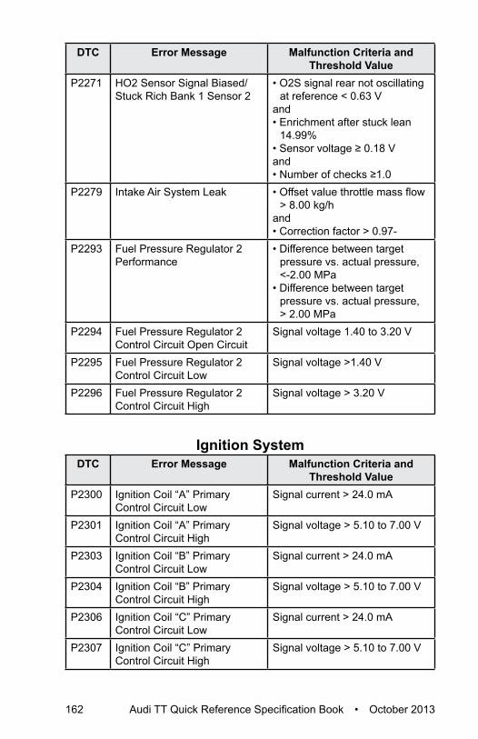
162 Audi TT Quick Reference Specification Book • October 2013
DTC Error Message Malfunction Criteria and Threshold Value
P2271 HO2 Sensor Signal Biased/Stuck Rich Bank 1 Sensor 2
• O2S signal rear not oscillating at reference < 0.63 V
and• Enrichment after stuck lean
14.99%• Sensor voltage ≥ 0.18 Vand• Number of checks ≥1.0
P2279 Intake Air System Leak • Offset value throttle mass flow > 8.00 kg/h
and• Correction factor > 0.97-
P2293 Fuel Pressure Regulator 2 Performance
• Difference between target pressure vs. actual pressure, <-2.00 MPa
• Difference between target pressure vs. actual pressure, > 2.00 MPa
P2294 Fuel Pressure Regulator 2 Control Circuit Open Circuit
Signal voltage 1.40 to 3.20 V
P2295 Fuel Pressure Regulator 2 Control Circuit Low
Signal voltage >1.40 V
P2296 Fuel Pressure Regulator 2 Control Circuit High
Signal voltage > 3.20 V
Ignition SystemDTC Error Message Malfunction Criteria and
Threshold ValueP2300 Ignition Coil “A” Primary
Control Circuit LowSignal current > 24.0 mA
P2301 Ignition Coil “A” Primary Control Circuit High
Signal voltage > 5.10 to 7.00 V
P2303 Ignition Coil “B” Primary Control Circuit Low
Signal current > 24.0 mA
P2304 Ignition Coil “B” Primary Control Circuit High
Signal voltage > 5.10 to 7.00 V
P2306 Ignition Coil “C” Primary Control Circuit Low
Signal current > 24.0 mA
P2307 Ignition Coil “C” Primary Control Circuit High
Signal voltage > 5.10 to 7.00 V

Audi TT Quick Reference Specification Book • October 2013 163
DTC
Cha
rt
DTC Error Message Malfunction Criteria and Threshold Value
P2309 Ignition Coil “D” Primary Control Circuit Low
Signal current > 24.0 mA
P2310 Ignition Coil “D” Primary Control Circuit High
Signal voltage > 5.10 to 7.00 V
Additional Emissions RegulationsDTC Error Message Malfunction Criteria and
Threshold ValueP2400 EVAP System Leak Detection
Pump Control Circuit/OpenSignal voltage > 4.40 to 5.60 V
P2401 EVAP System Leak Detection Pump Control Circuit Low
Signal voltage < 2.15 to 3.25 V
P2402 EVAP System Leak Detection Pump Control Circuit High
Signal current > 3.00 A
P2403 EVAP System Leak Detection Pump Sense Circuit/Open
Low signal voltage > 0.50 Sec.
P2404 EVAP System Leak Detection Pump Sense Circuit Range/Performance
• High signal voltage > 12..0 Sec.
and• Number of checks 30.00-.• Cumulative time of high signal
voltage during pumping > 50.0 Sec.
P2414 O2 Sensor Exhaust Sample Error Bank 1, Sensor 1
Threshold 1:• Signal voltage 3.10 to 4.81VThreshold 2:• Signal voltage 2.50 to 3.10V• Depending on gain factor,
that actual is used for sensor characteristic, the threshold is switched
P2539 Low Pressure Fuel System Sensor Circuit
Signal voltage > 4.9 V
P2541 Low Pressure Fuel System Sensor Circuit Low
Signal voltage < 0.2 V
P2569 Direct Ozone Reduction Catalyst Temperature Sensor Circuit Low
Signal voltage < 0.2 V
P2570 Direct Ozone Reduction Catalyst Temperature Sensor Circuit High
Signal voltage > 5.0 V

164 Audi TT Quick Reference Specification Book • October 2013
DTC Error Message Malfunction Criteria and Threshold Value
P2626 O2 Sensor Pumping Current Trim Circuit/Open Bank 1 Sensor 1
O2S signal front > 3.2 V

Audi of America reserves the right to change or update any part of this technical manual at any time. No legal commitment can therefore be derived from the information, illustrations or descriptions in this manual.
The texts, illustrations and standards in this manual are based on the information available at the time of printing. No part of this manual may be reprinted, reproduced or translated without the written permission of Audi of America.
All rights under the copyright laws are expressly reserved by Audi of America. Subject to alteration and amendment.
Printed in the United States© 2013 Audi of America, Inc.

October 2013