questions, projects, and labs chapter eight · questions, projects, and labs chapter eight 8.1 ......
TRANSCRIPT

Questions, Projects, and Laboratory Exercises
store a
g pro
Questions, Projects, and Labs Chapter Eight
8.1 Questions
1. What three components make up Von Neumann Machines?
2. What is the purpose of
a) The system bus
b) The address bus
c) The data bus
d) The control bus
3. Which bus defines the “size” of the processor?
4. Which bus controls how much memory you can have?
5. Does the size of the data bus control the maximum value the CPU can process? Explain.
6. What are the data bus sizes of:
a) 8088 b) 8086 c) 80286 d) 80386sx
e) 80386 f) 80486 g)Pentium h) Pentium II
7. What are the address bus sizes of the above processors?
8. How many “banks” of memory do each of the above processors have?
9. Explain how to store a word in byte addressable memory (that is, at what addresses). Explain how todouble word.
10. How many memory operations will it take to read a word from the following addresses on the followin-cessors?
11. Repeat the above for double words
Table 16: Memory Cycles for Word Accesses
$100 $101 $102 $103 $104 $105
8088
80286
80386
Table 17: Memory Cycles for Doubleword Accesses
$100 $101 $102 $103 $104 $105
8088
Beta Draft - Do not distribute © 2001, By Randall Hyde Page 355

Chapter Eight
Volume Two
d 80386
s.
ou are
states.
f refer
mem
12. Explain which addresses are best for byte, word, and doubleword variables on an 8088, 80286, anprocessor.
13. Given the system bus size, what address boundary is best for a real64 object in memory?
14. What is the purpose of the system clock?
15. What is a clock cycle?
16. What is the relationship between clock frequency and the clock period?
17. Explain why 10ns memory should not work on a 500 MHz Pentium III processor? Explain why it doe
18. What does the term “memory access time” mean?
19. What is a wait state?
20. If you are running an 80486 at the following clock speeds, how many wait states are required if yusing 80ns RAM (assuming no other delays)?
a) 20 MHz b) 25 MHz c) 33 MHz d) 50 MHz e) 100 MHz
21. If your CPU runs at 50 MHz, 20ns RAM probably won’t be fast enough to operate at zero wait Explain why.
22. Since sub-10ns RAM is available, why aren’t most systems zero wait state systems?
23. Explain how the cache operates to save some wait states.
24. What is the difference between spatial and temporal locality of reference?
25. Explain where temporal and spatial locality of reference occur in the following Pascal code:
while i < 10 do beginx := x * i;i := i + 1;
end;
26. How does cache memory improve the performance of a section of code exhibiting spatial locality o-ence?
27. Under what circumstances is a cache not going to save you any wait states?
28. What is the effective (average) number of wait states the following systems will operate under?
a) 80% cache hit ratio, 10 wait states (WS) for memory, 0 WS for cache.
b) 90% cache hit ratio; 7 WS for memory; 0 WS for cache.
c) 95% cache hit ratio; 10 WS memory; 1 WS cache.
d) 50% cache hit ratio; 2 WS memory; 0 WS cache.
29. What is the purpose of a two level caching system? What does it save?
30. What is the effective number of wait states for the following systems?
a) 80% primary cache hit ratio (HR) zero WS; 95% secondary cache HR with 2 WS; 10 WS for main-ory access.
80286
80386
Table 17: Memory Cycles for Doubleword Accesses
$100 $101 $102 $103 $104 $105
Page 356 © 2001, By Randall Hyde Beta Draft - Do not distribute

Questions, Projects, and Laboratory Exercises
ess.
ss.
g pro
m.
ister.
ister.
plain
e the
hy are
ck?
. Explain
on the
b) 50% primary cache HR, zero WS; 98% secondary cache HR, one WS; five WS for main memory acc
c) 95% primary cache HR, one WS; 98% secondary cache HR, 4 WS; 10 WS for main memory acce
32. In what HLA declaration section would you declare initialized values that must not be changed durin-gram execution?
33. In what HLA declaration section would you declare uninitialized variables?
34. In what HLA declaration section would you declare automatic variables?
35. Explain how you allocate and deallocate dynamic memory using the HLA Standard Library.
36. Provide two ways to take the address of a variable you declare in the STATIC section of your progra
37. What is the difference between the STORAGE and STATIC sections of your program?
38. Suppose you have a word variable, “w”, and you wish to load the L.O. byte of “w” into the AH regWhat MOV instruction could you use to achieve this?
39. Suppose you have a word variable, “w”, and you wish to load the H.O. byte of “w” into the AL regWhat MOV instruction could you use to achieve this?
40. What is the difference between “add( 1, [eax]);” and “add( 0, [eax+1]);”?
41. By default, the “stdout.put( eax );” statement will print EAX as an eight-digit hexadecimal value. Exhow to tell stdout.put to print EAX as an unsigned 32-bit integer; as a signed 32-bit integer. Providactual instructions to accomplish this.
42. Explain, step by step, what the “PUSH( EAX );” instruction does.
43. Explain, step by step, what the “POP( EAX );” instruction does.
44. What is the purpose of the PUSHW and PUSHD instructions? What kind of data do they push? Wthere no POPW and POPD instructions?
45. What is the purpose of the “PUSHAD();” instruction? In what order does it push its data onto the sta
46. Suppose you execute the following three instructions:
push( eax );pop( bx );pop( cx );
What value will be left in BX after this sequence? What value will be left in CX?
47. Suppose you needed to save the value of the carry flag across the execution of several instructionshow you could do this (and provide the code).
48. Suppose you’ve executed the following two instructions to push EAX and EBX onto the stack:
push( eax );push( ebx );
Without popping any data off the stack, explain how you can reload EAX’s value that was pushed stack. Provide a single instruction that will do this.
49. What is the difference between the “DEC( EAX );” instruction and the “SUB( 1, EAX );” instruction?
50. How can you check for unsigned arithmetic overflow immediately after an “INC( EAX );” instruction?
51. What is the identity element (if any) with respect to
a) AND b) OR c) XOR d) NOT e) NAND f) NOR
52. Provide truth tables for the following functions of two input variables:
a) AND b) OR c) XOR d) NAND e) NOR
f) Equivalence g) A < B h) A > B i) A implies B
53. Provide the truth tables for the following functions of three input variables:
Beta Draft - Do not distribute © 2001, By Randall Hyde Page 357

Chapter Eight
Volume Two
uestion
e vari
Q’=0.
a) ABC (and) b) A+B+C (OR) c) (ABC)’ (NAND)d) (A+B+C)’ (NOR)
e) Equivalence (ABC) + (A’B’C’)f) XOR (ABC + A’B’C’)’
54. Provide schematics (electrical circuit diagrams) showing how to implement each of the functions in qthree using only two-input gates and inverters. E.g.,
A) ABC =
55. Provide implementations of an AND gate, OR gate, and inverter gate using one or more NOR gates.
56. What is the principle of duality? What does it do for us?
57. Build a single truth table that provides the outputs for the following three boolean functions of thre-ables:
Fx= A + BC
Fy - AB + C’B
Fz = A’B’C’ + ABC + C’B’A
58. Provide the function numbers for the three functions in question seven above.
59. How many possible (unique) boolean functions are there if the function has
a) one inputb) two inputs c) three inputs d) four inputs e) five inputs
60. Simplify the following boolean functions using algebraic transformations. Show your work.
a) F = AB + AB’ b) F = ABC + BC’ + AC + ABC’
c) F = A’B’C’D’ + A’B’C’D + A’B’CD + A’B’CD’
d) F = A’BC + ABC’ + A’BC’ + AB’C’ + ABC + AB’C
61. Simplify the boolean functions in question 60 using the mapping method.
62. Provide the logic equations in canonical form for the boolean functions S0..S6 for the seven segment display(see “Combinatorial Circuits” on page 223).
63. Provide the truth tables for each of the functions in question 62
64. Minimize each of the functions in question 62 using the map method.
65. The logic equation for a half-adder (in canonical form) is
Sum = AB’ + A’B Carry = AB
a) Provide an electronic circuit diagram for a half-adder using AND, OR, and Inverter gates
b) Provide the circuit using only NAND gates
66. The canonical equations for a full adder take the form:
Sum = A’B’C + A’BC’ + AB’C’ + ABC
Carry = ABC + ABC’ + AB’C + A’BC
a) Provide the schematic for these circuits using AND, OR, and inverter gates.
b) Optimize these equations using the map method.
c) Provide the electronic circuit for the optimized version (using AND, OR, and inverter gates).
67. Assume you have a D flip-flop (use this definition in this text) whose outputs currently are Q=1 andDescribe, in minute detail, exactly what happens when the clock line goes
a) from low to high with D=0
A
B
CABC
Page 358 © 2001, By Randall Hyde Beta Draft - Do not distribute

Questions, Projects, and Laboratory Exercises
he?
ution
one big
b) from high to low with D=0
68. Rewrite the following Pascal statements to make them more efficient:
a) if (x or (not x and y)) then write(‘1’);
b) while(not x and not y) do somefunc(x,y);
c) if not((x <> y) and (a = b)) then Something;
69. Provide canonical forms (sum of minterms) for each of the following:
a) F(A,B,C) = A’BC + AB + BCb) F(A,B,C,D) = A + B + CD’ + D
c) F(A,B,C) = A’B + B’A d) F(A,B,C,D) = A + BD’
e) F(A,B,C,D) = A’B’C’D + AB’C’D’ + CD + A’BCD’
70. Convert the sum of minterms forms in question 69 to the product of maxterms forms.
71. What is the difference between the Harvard and the Von Neumann Architectures?
72. Explain how encoding instructions in binary saves space in an opcode (see “Basic CPU Design” on page 245).
73. What is the difference between Random Logic and Microcode?
74. What do the following acronyms stand for? CISC, RISC, VLIW.
75. Is the LOOP instruction a “RISC Core” or a “Complex” instruction? Explain.
76. What is the difference between an 80x86 “RISC Core” and a “Complex” instruction?
77. What sequence of instructions is the LOOP instruction equivalent to?
78. Explain, step-by-step, how a MOV instruction might work.
79. Explain how CPU designers use parallelism to increase the CPU’s throughput (# of instrs/second).
80. What is a prefetch queue?
81. What is pipelining?
82. What is a pipeline stall?
83. How can creating separate instruction and data caches improve performance?
84. Why do separate instruction and data caches often operate at a greater miss rate than a unified cac
85. What is a data hazard?
86. What is a superscalar CPU?
87. Explain how “out of order” execution works. Under what circumstances can “out of order” execimprove performance?
88. What is “register renaming?” How can it improve performance?
89. Explain the following terms: SISD, SIMD, MIMD.
90. Are MMX instructions SISD, SIMD, or MIMD?
91. Provide four reasons why we can’t/shouldn’t design a CPU with as many instructions as possible.
92. Explain why, when decoding an instruction, it is better to use several smaller decoders rather thandecoder.
93. Explain how to use an opcode prefix byte to extend an instruction set.
94. What is the value of the opcode prefix byte on the 80x86 CPU?
95. What is the maximum length of an 80x86 instruction?
96. What is the purpose of the MOD-REG-R/M byte on the 80x86?
97. What is the purpose of the SIB byte on the 80x86?
98. How long (in bytes) is the 80x86 opcode?
Beta Draft - Do not distribute © 2001, By Randall Hyde Page 359

Chapter Eight
Volume Two
oes the
Linux)?
ory to
register
different
e?
would a nces for
perfor
g on a
99. When encoding an instruction with a memory addressing mode that has a displacement, where d80x86 expect the displacement value to appear?
100.On the 80x86, how do you encode immediate constant within the instruction?
101.What are the displacement sizes that the 80x86 supports for memory operands (under Windows andHint: this one is a little tricky.
102.How do you select the displacement size in the instruction encoding?
103.Based on the values in the MOD-REG-R/M byte, explain why the 80x86 instructions don’t allow memmemory operations.
104.Explain why there is no “[EBP]” addressing mode on the 80x86.
105.The “[ESP]” address mode requires an SIB byte even though this instruction doesn’t have an indexassociated with it. Explain.
106.80x86 opcodes only have one bit to specify the operand size. Explain how the 80x86 encodes threeoperand sizes.
107.Under Linux and Windows, what are the two default operand sizes?
108.What is an alternate instruction encoding?
109.What is the memory hierarchy?
110.What is the difference between a direct-mapped cache and a fully associative cache?
111.What is the difference between a two-way set associative cache and a four-way set associative cach
112.Why would a direct-mapped cache offer better performance than a fully associative cache? Why fully associative cache offer better performance than a direct-mapped cache? Give the circumstaboth.
113.What is the difference between the write-through and the write-back cache policies? Which is higher-mance? Which is best in a multiprocessor system?
114.What is paging?
115.What is virtual memory?
116.What is thrashing?
117.What does NUMA stand for? How can it affect the performance of your programs?
118.What is the difference between the read-only, write-only, read/write, and dual I/O ports?
119.If the CPU sees a port as read/write, how does the external world see that port (input, output, both)?
120.What is the difference between I/O-mapped input/output and memory-mapped input/output?
121.What is DMA? Explain, don’t just spell out the acronym.
122.What is polling?
123.What are the relative speed differences between low, medium, and high speed I/O devices?
124.How are busses like PCI and ISA different than the CPU’s address and data busses?
125.Which bus is higher performance, PCI or ISA? Give performance numbers to back up your claim.
126.What is the AGP bus and what advantage does it have over the PCI bus?
127.What is I/O buffering? How can it keep a system from losing data?
128.What is the purpose of handshaking?
129.What is a time-out? What are some convienent instructions for checking for a time-out while waitinbit in an I/O port?
130.What is the difference between interrupt driven I/O and polled I/O?
Page 360 © 2001, By Randall Hyde Beta Draft - Do not distribute

Questions, Projects, and Laboratory Exercises
number wer than r enters use after
rs (don’t
). y in the en free
lues in
he user, p in the 2 bytes integer. many
of these er will
rst tension ete.
a each side
ule to of them special by which r’s symscreen. mouse.
integer aracters d by the
ing the ursor cter posi
n the t( 10, 10, at by the of bytes lloc and se to it.
8.2 Programming Projects
1. Write a program that requests a number from the user and then allows the user to enter the specifiedof characters. Display the characters in the reverse order the user enters them. If the user enters fethe specified number of characters, fill the remainder of your buffer with spaces. Repeat until the usezero as the number of characters to read. Be sure to free up any dynamically allocated storage you displaying the user output.
2. Write a program that requests a count from the user and allocates storage for that many 32-bit integeforget to multiply the count by four since int32 objects are four bytes long; use SHL to multiply by fourThe program should then read the specified number of integers from the user and store them awaallocated buffer. Finally, the program should sum up each value in the buffer, display the sum, and ththe allocated storage and quit.
3. Modify program (2) above so that it reports the largest (maximum) and smallest (minimum) integer vathe buffer.
4. Write a program that allocates a buffer containing 32 bytes of storage, reads an integer value from tand then copies each bit from the integer into successive bytes of memory; that is, bit zero winds ufirst byte, bit 1 winds up in the second byte, etc. When your program is done copying the bits, the 3should all contain a zero or a one depending upon the setting of the corresponding bit in the input Write each of these bits to the display. Sum the 32 bits up and print the sum (which tells you howone-bits were in the number). Be sure to free the storage before your program quits.
5. Write a program that allocates storage for two buffers. A single user input should determine the size two buffers: the first buffer will contain the number of bytes specified by the user and the second buffcontain four times this many bytes. Read a sequence of int8 values from the user and store them into the fibuffer. The copy the values from first buffer to consecutive dwords in the second buffer, using sign exto convert the values. Display both buffers using hexadecimal notation once the conversion is compl
6. (Windows Only) Using HLA Standard Library console.fillRect procedure, write a program that generatescheckerboard pattern on the screen. The user should be able to specify the number of squares on of the checkerboard as well as the two colors to use for the checkerboard display.
7. (Windows Only) Write a two-player tic-tac-toe game. Use the HLA Standard Library console modclear the screen and draw the board between each move. Let the users alternate moves until onedecides to quit (don’t bother trying to have your program determine if the game is over, just use a input value to end the game). Be sure to draw a second game board listing numbers or characters each player can choose the square into which they want to move. Use different colors for each playe-bols. If you want to get real fancy, you can draw the X’s and O’s by printing blocks of spaces on the If you really want to be impressive, read the HLA console documentation and learn how to use the Then use mouse clicks to make the moves (this is optional!).
8. (Windows Only) Write a program that inputs an (x,y) coordinate from the user and a single unsigned value. Your program should draw a rectangle on the screen using the PC’s line drawing graphic ch(see Appendix B). The upper left hand corner of the rectangle should be at the coordinate specifieuser. The integer value specifies the width and height of the rectangle on the screen. Before drawrectangle, verify that it will fit in an 80x25 window. Use the console.gotoxy procedure to position the cbefore drawing each character; do not disturb any other characters on the screen except those chara-tions where you actually draw one of the line drawing characters.
9. (Windows Only) The HLA “console.getRect( top, left, bottom, right, buffer )” function copies the data ispecified rectangle on the screen to the buffer passed as the last parameter. E.g., “console.getRec20, 20, (type byte [eax]));” copies the 10x10 matrix of characters into the block of memory pointedEAX. Similarly, the “console.putRect( top, left, bottom, right, buffer);” call will copy the data from specified buffer to the screen at the specified coordinates. The buffer must contain twice the number as there are characters in the rectangular region. Allocate a sufficient amount of storage using mathen use these two routines to temporarily save a portion of the screen while you write something elThen, upon prompt from the program’s user, restore the original rectangle.
Beta Draft - Do not distribute © 2001, By Randall Hyde Page 361

Chapter Eight
Volume Two
th table nput for each
f two
f three
f four
nction
10) Write a program that reads four values from the user, I, J, K, and L, and plugs these values into a truwith B’A’ = I, B’A = J, BA’ = K, and BA = L. Ensure that these input values are only zero or one. Then ia series of pairs of zeros or ones from the user and plug them into the truth table. Display the result computation.
11) Write a program that, given a 4-bit logic function number, displays the truth table for that function ovariables.
12) Write a program that, given an 8-bit logic function number, displays the truth table for that function ovariables.
13) Write a program that, given a 16-bit logic function number, displays the truth table for that function ovariables.
14) Write a program that, given a 16-bit logic function number, displays the canonical equation for that fu(hint: build the truth table).
Page 362 © 2001, By Randall Hyde Beta Draft - Do not distribute

Questions, Projects, and Laboratory Exercises
es
using
er
s
8.3 Chapters One and Two Laboratory Exercises
Accompanying this text is a significant amount of software. This software can be found in the AoA directory. Inside this directory are a set of subdirectories with names like volume2 and volume3. Inside those directories are files with names like ch02 and ch03 with the names obviously corresponding to chap-ters in this text. The code for these laboratory exercises appears in the volume2\ch08 subdirectory. Please see this directory for more details.
8.3.1 Memory Organization Exercises
The following program (Program 8.1) demonstrates the memory layout of an HLA program. It do this by declaring variables or other symbols in each of the various run-time memory segments. This pro-gram uses the LEA instruction to take the address of each memory object and then displays the address hexadecimal notation. Run this program and compare the addresses of each of the objects.
For your lab report, compare the output addresses against the memory layout presented in this chapt. Since each memory segment begins on a 4096 byte ($1000) boundary, what clues do the output addresse give us concerning the grouping of variables in the memory segments? Given the output of this program, and the address of some other variable declared in this program, describe how you could determine which segment that other variable is in given no other information than the variable’s location.
// Sample program for Memory Organization Laboratory Exercise// in “The Art of Assembly Language Programming”// (HLA Edition).
program MemOrg;#include( “stdlib.hhf” );
// Declare a set of variables in each of the// different memory sections so we can compare// their addresses in memory.
var AutoVar: int32; static StaticVar: int32; DataVar: int32; @nostorage; dword 0; readonly ROVar: int32 := 0; storage StorageVar: int32; begin MemOrg;
// Take the address of each of the variables (plus allocate // storage for a dynamic variable) and display the addresses. lea( eax, AutoVar ); stdout.put( “AutoVar address in memory is: $”, eax, nl );
Beta Draft - Do not distribute © 2001, By Randall Hyde Page 363

Chapter Eight Volume Two
ckn
ry
ly
lea( eax, StaticVar ); stdout.put( “StaticVar address in memory is: $”, eax, nl ); lea( eax, DataVar ); stdout.put( “DataVar address in memory is: $”, eax, nl ); lea( eax, ROVar ); stdout.put( “ROVar address in memory is: $”, eax, nl ); lea( eax, StorageVar ); stdout.put( “StorageVar address in memory is: $”, eax, nl ); // Dynamically allocate a variable on the heap. malloc( 4 ); stdout.put( “Dynamic variable address in memory is: $”, eax, nl ); free( eax ); // The following code computes the address of this instruction // in memory: CodeAdrs: lea( eax, CodeAdrs ); stdout.put( “CodeAdrs label’s address in memory is: $”, eax, nl ); // Just to put things into perspective, display the value of the // stack pointer as well: stdout.put( “Stack Pointer contains the address: $”, esp, nl );
end MemOrg;
Program 8.1 Demonstration of Memory Sections
8.3.2 Data Alignment Exercises
The following program lets you test the effect of data alignment on your program. It allocates a blo of 1,000,000 dword values and then runs through two loops that access these values on an address that is a even multiple of four and at an address that is not an even multiple of four. By measuring the time these two code fragments take to execute, you can compare the difference between aligned and non-aligned memo access.
Note: keep in mind that Linux and Windows are multi-tasking operating systems. Therefore, the differ-ence in execution time will not be as great as you might expect because a large percentage of the execution time you measure with this program will be spent in another process. You can assume that approximate the same amount of time is spent outside this process in both halves of the program.
To avoid optimizations by the cache hardware, this program accesses data at over four million different addresses. The fact that most memory accesses will experience a cache miss will also skew the timings (and make them more similar). Finally, different processors (e.g., Pentium vs. Pentium II vs. K6 vs. Athlon) have different penalties for misaligned data. Hence, you should expect to see only a small percentage difference between the two halves of the following program.
Page 364 © 2001, By Randall Hyde Beta Draft - Do not distribute
Questions, Projects, and Laboratory Exercises
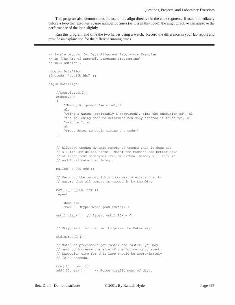
This program also demonstrates the use of the align directive in the code segment. If used immediately before a loop that executes a large number of times (as it is in this code), the align directive can improve the performance of the loop slightly.
Run this program and time the two halves using a watch. Record the difference in your lab report and provide an explanation for the different running times.
// Sample program for Data Alignment Laboratory Exercise// in “The Art of Assembly Language Programming”// (HLA Edition).
program DataAlign;#include( “stdlib.hhf” );
begin DataAlign;
//console.cls(); stdout.put ( “Memory Alignment Exercise”,nl, nl, “Using a watch (preferably a stopwatch), time the execution of”, nl “the following code to determine how many seconds it takes to”, nl “execute.”, nl nl “Press Enter to begin timing the code:” ); // Allocate enough dynamic memory to ensure that it does not // all fit inside the cache. Note: the machine had better have // at least four megabytes free or virtual memory will kick in // and invalidate the timing. malloc( 4_000_000 ); // Zero out the memory (this loop really exists just to // ensure that all memory is mapped in by the OS). mov( 1_000_000, ecx ); repeat dec( ecx ); mov( 0, (type dword [eax+ecx*4])); until( !ecx ); // Repeat until ECX = 0.
// Okay, wait for the user to press the Enter key. stdin.readLn(); // Note: as processors get faster and faster, you may // want to increase the size of the following constant. // Execution time for this loop should be approximately // 10-30 seconds. mov( 1000, edx ); add( 30, eax ); // Force misalignment of data.
Beta Draft - Do not distribute © 2001, By Randall Hyde Page 365

Chapter Eight Volume Two
repeat mov( 999_992, ecx ); align( 16 ); repeat sub( 4, ecx ); mov( [eax+ecx*4], ebx ); mov( [eax+ecx*4], ebx ); mov( [eax+ecx*4], ebx ); mov( [eax+ecx*4], ebx ); until( !ecx ); dec( edx ); until( !edx ); // Repeat until EAX is zero. stdout.put( stdio.bell, “Stop timing and record time spent”, nl, nl );
// Okay, time the aligned access. stdout.put ( “Press Enter again to begin timing access to aligned variable:” ); stdin.readLn(); // Note: if you change the constant above, be sure to change // this one, too! mov( 1000, edx ); add( 30, eax ); // Realign the data. repeat mov( 999_992, ecx ); align( 16 ); repeat sub( 4, ecx ); mov( [eax+ecx*4], ebx ); mov( [eax+ecx*4], ebx ); mov( [eax+ecx*4], ebx ); mov( [eax+ecx*4], ebx ); until( !ecx ); dec( edx ); until( !edx ); // Repeat until EAX is zero. stdout.put( stdio.bell, “Stop timing and record time spent”, nl, nl ); free( eax );
end DataAlign;
Program 8.2 Data Alignment Exercise
Page 366 © 2001, By Randall Hyde Beta Draft - Do not distribute

Questions, Projects, and Laboratory Exercises
n
8.3.3 Readonly Segment Exercises
The following exercise demonstrates that you cannot write data to a readonly variable. The variable i,appearing in the READONLY section, generates an ex.AccessViolation exception if you attempt to write to it. Run this program and document what happens in your lab report. Explain how you might use REA-DONLY variables in your program to protect against errors in your code.
// Sample program for Read Only Data Laboratory Exercise// in “The Art of Assembly Language Programming”// (HLA Edition).
program ReadOnlyDemo;#include( “stdlib.hhf” );
readonly i:int32 := 10;
begin ReadOnlyDemo;
stdout.put( “i = “, i, nl ); try
mov( 0, i ); stdout.put( “Now i contains “, i, nl );
exception( ex.AccessViolation )
stdout.put( “Error attempting to write to variable ‘i’”, nl );
endtry;
end ReadOnlyDemo;
Program 8.3 READONLY Variable Demonstration
8.3.4 Type Coercion Exercises
The HLA type coercion operators are actually useful for many things besides letting you load a portio of a variable into a smaller register (the primary example this chapter has given thus far). Many HLA instructions and Standard Library routines use the type information associated with a variable to determine how to use that variable. For example, the stdout.put routine in the Standard Library determines how to dis-play a value based on its type. For example, if you have an int32 variable, i32, and you decide to print it with stdout.put, it will use the type information to determine that it must print this value as a signed 32-bit integer. This laboratory exercise demonstrates that you can use the type coercion operators to display a value as a different type.
Compile and run the following program that demonstrates how to display an int32 variable (testVar) using hexadecimal notation:
// Sample program for Coercion Laboratory Exercise
Beta Draft - Do not distribute © 2001, By Randall Hyde Page 367
Chapter Eight Volume Two
0
lab
// in “The Art of Assembly Language Programming”// (HLA Edition).
program Coercion;#include( “stdlib.hhf” );
static testVar:int32;
begin Coercion;
stdout.put( “Enter a 32-bit signed integer value: “ ); stdin.get( testVar ); stdout.put ( nl, “In decimal: “, testVar, nl “In hexadecimal: $”, (type dword testVar), nl ); end Coercion;
Program 8.4 Type Coercion Exercise
After running this program and noting the results, modify the type of testVar so that it is a real32 vari-able. Rerun the program. Based on what you’ve learned from Chapter Two, explain the output when you enter 1.0 as the real value. Note that you can also use type coercion in the stdin.get routine. Type cast the testVar parameter in stdin.get so that it is a real32 object. Rerun the program and explain the results in your lab report.
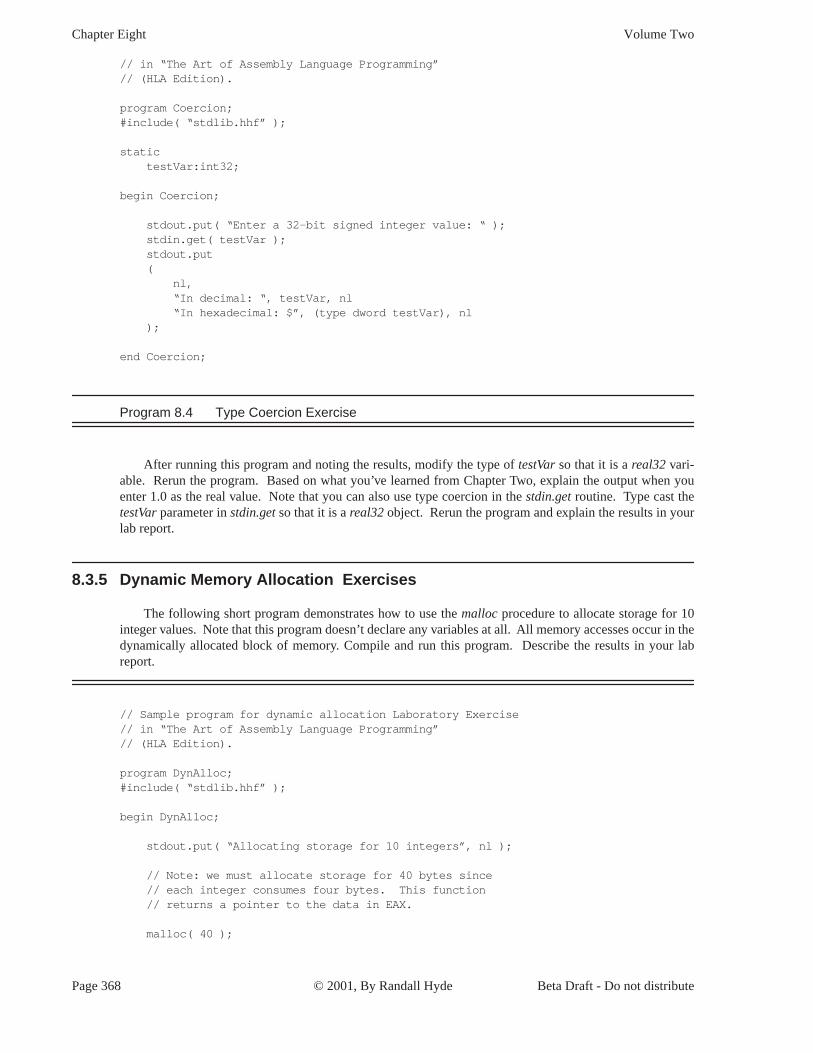
8.3.5 Dynamic Memory Allocation Exercises
The following short program demonstrates how to use the malloc procedure to allocate storage for 1 integer values. Note that this program doesn’t declare any variables at all. All memory accesses occur in the dynamically allocated block of memory. Compile and run this program. Describe the results in your report.
// Sample program for dynamic allocation Laboratory Exercise// in “The Art of Assembly Language Programming”// (HLA Edition).
program DynAlloc;#include( “stdlib.hhf” );
begin DynAlloc;
stdout.put( “Allocating storage for 10 integers”, nl ); // Note: we must allocate storage for 40 bytes since // each integer consumes four bytes. This function // returns a pointer to the data in EAX. malloc( 40 );
Page 368 © 2001, By Randall Hyde Beta Draft - Do not distribute

Questions, Projects, and Laboratory Exercises
y
n
// Move pointer to storage to the ESI register so we // can use EAX for other purposes. mov( eax, esi ); // Prompt the user to enter a value: stdout.put( “Enter a integer to initialize the data with: “ ); stdin.geti32(); // Use the input value as a starting value with which to // initialize the storage we’ve just created: stdout.newln(); for( mov( 0, ebx ); ebx < 10; inc( ebx )) do mov( eax, [esi+ebx*4] ); inc( eax ); endfor; // Okay, display these values from the allocated storage: for( mov( 0, ebx ); ebx < 10; inc( ebx )) do mov( [esi+ebx*4], eax ); stdout.put ( “Value[“, (type uns32 ebx), “] = “, (type int32 eax), nl ); endfor; // Free up the storage allocated above. stdout.put( nl, “Freeing storage:”, nl ); free( esi ); end DynAlloc;
Program 8.5 MALLOC and FREE Exercise
Modify this program to read and display 20 characters rather than 10 integers. Describe the necessar changes in your lab report and include a copy of the new program with your lab report.
8.4 Chapter Three Laboratory Exercises
This laboratory uses several Windows programs to manipulate truth tables and logic expressions, opti-mize logic equations, and simulate logic equations. These programs will help you understand the relatio-ship between logic equations and truth tables as well as gain a fuller understanding of logic systems.
Beta Draft - Do not distribute © 2001, By Randall Hyde Page 369

Chapter Eight Volume Two
s out
t
th table
al
ifrintn in
ua
v
set at
The WLOGIC.EXE program simulates logic circuitry. WLOGIC stores several logic equations that describe an electronic circuit and then it simulates that circuit using “switches” as inputs and “LEDs” a-puts.
8.4.1 Truth Tables and Logic Equations Exercises
In this laboratory exercise you will create several different truth tables of two, three, and four variables. The TRUTHTBL.EXE program (found in the Volume2\Ch08 subdirectory) will automatically convert the truth tables you input into logic equations in the sum of minterms canonical form.
The TRUTHTBL.EXE program provides three buttons that let you choose a two variable, three variable, or four variable truth table. Pressing one of these buttons rearranges the truth table in an appropriate fashion. By default, the TRUTHTBL program assumes you want to work with a four variable truth table. Try press-ing the Two Variables, Three Variables, and Four Variables buttons and observe the results. Describe wha happens in your lab report.
To change the truth table entries, all you need do is click on the square associated with the tru value you want to change. Clicking on one of these boxes toggles (inverts) that value in that square. For example, try clicking on the DCBA square several times and observe the results.
Note that as you click on different truth table entries, the TRUTHTBL program automatically recom-putes the sum of minterms canonical logic equation and displays it at the bottom of the window. What equa-tion does the program display if you set all squares in the truth table to zero?1
Set up the TRUTHTBL program to work with four variables. Set the DCBA square to one. Now press the Two Variables button. Press the Four Variables button and set all the squares to one. Now press the Two Variables button again. Finally, press the Four Variables button and examine the results. What does the TRUTHTBL program do when you switch between different sized truth tables? Feel free to try addition experiments to verify your hypothesis. Describe your results in your lab report.
Switch to two variable mode. Input the truth tables for the logical AND, OR, XOR, and NAND truth tables. Verify the correctness of the resulting logic equations. Write up the results in your lab report. Note: there is a printer attached to your computer, you can print each truth table you create by pressing the P button in the window. This makes it very easy to include the truth table and corresponding logic equatio your lab report. For additional credit: input the truth tables for all 16 functions of two variables. In your lab report, present the results for these 16 functions.
Design several two, three, and four variable truth tables by hand. Manually determine their logic eq-tions in sum of minterms canonical form. Input the truth tables and verify the correctness of your logic equa-tions. Include your hand designed truth tables and logic equations as well as the machine produced ersions in your lab report.
Consider the following layout for a seven-segment display:
Here are the segments to light for the binary values DCBA = 0000..1001:
1. Note: On initial entry to the program, TRUTHTBL does not display a logic equation. Therefore, you will need toleast one square to one and then back to zero to see this equation.
E
F GH
KI J
Page 370 © 2001, By Randall Hyde Beta Draft - Do not distribute

Questions, Projects, and Laboratory Exercises
d then
the
as
tions
The
es log
fol
nd logi- operator
E = D’C’B’A’ + D’C’BA’ + D’C’BA + D’CB’A + D’CBA’ + D’CBA + DC’B’A’ + DC’B’AF = D’C’B’A’+ D’CB’A’ + D’CB’A + D’CBA’ + DC’B’A’ + DC’B’AG = D’C’B’A’ + D’C’B’A + D’C’BA’ + D’C’BA + D’CB’A’ + D’CBA + DC’B’A’ + DC’B’AH = D’C’BA’ + D’C’BA + D’CB’A’ + D’CB’A + D’CBA’ + DC’B’A’ + DC’B’AI = D’C’B’A’ + D’C’BA’ + D’CBA’ + DC’B’A’J = D’C’B’A’ + D’C’B’A + D’C’BA + D’CB’A’ + D’CB’A +D’CBA’ + D’CBA + DC’B’A’ + DC’B’AK = D’C’B’A’ + D’C’BA’ + D’C’BA + D’CB’A + D’CBA’ + DC’B’A’
Convert each of these logic equations to a truth table by setting all entries in the table to zero an clicking on each square corresponding to each minterm in the equation. Verify by observing the equation that TRUTHTBL produces that you’ve successfully converted each equation to a truth table. Describe results and provide the truth tables in your lab report.
For Additional Credit: Modify the equations above to include the following hexadecimal characters. Determine the new truth tables and use the TRUTHTBL program to verify that your truth tables and logic equations are correct.
8.4.2 Canonical Logic Equations Exercises
In this laboratory you will enter several different logic equations and compute their canonical forms well as generate their truth table. In a sense, this exercise is the opposite of the previous exercise where you generated a canonical logic equation from a truth table.
This exercise uses the CANON.EXE program found in the Volume2\Ch08 subdirectory. Run this pro-gram from Windows by double clicking on its icon. This program displays a text box, a truth table, and sev-eral buttons. Unlike the TRUTHTBL.EXE program from the previous exercise, you cannot modify the truth table in the CANON.EXE program; it is a display-only table. In this program you will enter logic equa in the text entry box and then press the “Compute” button to see the resulting truth table. This program also produces the sum of minterms canonical form for the logic equation you enter (hence this program’s name).
Valid logic equations take the following form:
• A term is either a variable (A, B, C, or D) or a logic expression surrounded by parentheses.
• A factor is either a term, or a factor followed by the prime symbol (an apostrophe, i.e., “‘”). prime symbol logically negates the factor immediately preceding it.
• A product is either a factor, or a factor concatenated with a product. The concatenation denot-ical AND operation.
• An expression is either a product or a product followed by a “+” (denoting logical OR) and-lowed by another expression.
Note that logical OR has the lowest precedence, logical AND has an intermediate precedence, acal NOT has the highest precedence of these three operators. You can use parentheses to override
Beta Draft - Do not distribute © 2001, By Randall Hyde Page 371
Chapter Eight Volume Two
h
and.
ing
ne if
d,
n
precedence. The logical NOT operator, since its precedence is so high, applies only to a variable or a paren-thesized expression. The following are all examples of legal expressions:
AB’C + D(B’+C’)AB(C+D)’ + A’B’(C+D)A’B’C’D’ + ABCD + A(B+C)(A+B)’ + A’B’
For this set of exercises, you should create several logic expression and feed them throug CANON.EXE. Include the truth tables and canonical logic forms in your lab report. Also verify that the the-orems appearing in this chapter (See “Boolean Algebra” on page 203.) are valid by entering each side of the theorem and verifying that they both produce the same truth table (e.g., (AB)’ = A’ + B’). For additional credit, create several complex logic equations and generate their truth tables and canonical forms by h Then input them into the CANON.EXE program to verify your work.
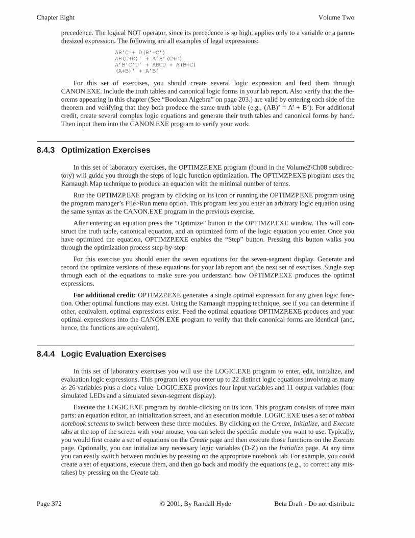
8.4.3 Optimization Exercises
In this set of laboratory exercises, the OPTIMZP.EXE program (found in the Volume2\Ch08 subdirec-tory) will guide you through the steps of logic function optimization. The OPTIMZP.EXE program uses the Karnaugh Map technique to produce an equation with the minimal number of terms.
Run the OPTIMZP.EXE program by clicking on its icon or running the OPTIMZP.EXE program using the program manager’s File>Run menu option. This program lets you enter an arbitrary logic equation us the same syntax as the CANON.EXE program in the previous exercise.
After entering an equation press the “Optimize” button in the OPTIMZP.EXE window. This will con-struct the truth table, canonical equation, and an optimized form of the logic equation you enter. Once you have optimized the equation, OPTIMZP.EXE enables the “Step” button. Pressing this button walks you through the optimization process step-by-step.
For this exercise you should enter the seven equations for the seven-segment display. Generate and record the optimize versions of these equations for your lab report and the next set of exercises. Single step through each of the equations to make sure you understand how OPTIMZP.EXE produces the optimal expressions.
For additional credit: OPTIMZP.EXE generates a single optimal expression for any given logic func-tion. Other optimal functions may exist. Using the Karnaugh mapping technique, see if you can determi other, equivalent, optimal expressions exist. Feed the optimal equations OPTIMZP.EXE produces and your optimal expressions into the CANON.EXE program to verify that their canonical forms are identical (an hence, the functions are equivalent).
8.4.4 Logic Evaluation Exercises
In this set of laboratory exercises you will use the LOGIC.EXE program to enter, edit, initialize, and evaluation logic expressions. This program lets you enter up to 22 distinct logic equations involving as many as 26 variables plus a clock value. LOGIC.EXE provides four input variables and 11 output variables (four simulated LEDs and a simulated seven-segment display).
Execute the LOGIC.EXE program by double-clicking on its icon. This program consists of three mai parts: an equation editor, an initialization screen, and an execution module. LOGIC.EXE uses a set of tabbed notebook screens to switch between these three modules. By clicking on the Create, Initialize, and Executetabs at the top of the screen with your mouse, you can select the specific module you want to use. Typically, you would first create a set of equations on the Create page and then execute those functions on the Executepage. Optionally, you can initialize any necessary logic variables (D-Z) on the Initialize page. At any time you can easily switch between modules by pressing on the appropriate notebook tab. For example, you could create a set of equations, execute them, and then go back and modify the equations (e.g., to correct any mis-takes) by pressing on the Create tab.
Page 372 © 2001, By Randall Hyde Beta Draft - Do not distribute

Questions, Projects, and Laboratory Exercises
ur
s e (#). e result
can ariable the fol
the
once
ging.
s. For
uations
te the ob-
to the
bles.
The Create page lets you add, edit, and delete logic equations. Logic equations may use the variables A-Z plus the “#” symbol (“#” denotes the clock). The equations use a syntax that is very similar to the logic expressions you’ve used in previous exercises in this chapter. In fact, there are only two major differences between the functions LOGIC.EXE allows and the functions that the other programs allow. First, LOGIC.EXE lets you use the variables A-Z and “#” (the other programs only let you enter functions of fo variables using A-D). The second difference is that LOGIC.EXE functions must take the form:
variable = expression
where variable is a single alphabetic character E-Z2 and expression is a logic expression using the variableA-Z and #. An expression may use a maximum of four different variables (A-Z) plus the clock valuDuring the expression evaluation, the LOGIC.EXE program will evaluate the expression and store thinto the specified destination variable.
If you enter more than four variables, LOGIC.EXE will complain about your expression. LOGIC.EXEonly evaluation expressions that contain a maximum of four alphabetic characters (not counting the vto the left of the equals sign). Note that the destination variable may appear within the expression; -lowing is perfectly legal:
F = FA+FB
This expression would use the current value of F, along with the current values of A and B to compute new value for F.
Unlike a programming language like “C++”, LOGIC.EXE does not evaluate this expression onlyand store the result into F. It will evaluate the expression several times until the value for F stabilizes. That is, it will evaluate the expression several times until the evaluation produces the same result twice in a row. Certain expressions will produce an infinite loop since they will never produce the same value twice in a row. For example, the following function is unstable:
F = F’
Note that instabilities can cross function boundaries. Consider the following pair of equations:
F = GG = F’
LOGIC.EXE will attempt to execute this set of equations until the values for the variables stop chanHowever, the system above will produce an infinite loop.
Sometimes a system of logic equations will only produce an infinite loop given certain data valueexample, consider the following of logic equation:
F = GF’ + G’F (F = G xor F)
If G’s value is one, this system is unstable. If G’s value is zero, this equation is stable. Unstable eqlike this one are somewhat harder to discover.
LOGIC.EXE will detect and warn you about logic system instabilities when you attempt to execulogic functions. Unfortunately, it will not pinpoint the problem for you; it will simply tell you that the prlem exists and expect you to fix it.
The A-D, E-K, and W-Z variables are special. A-D are read-only input variables. E-K correspond seven segments of a simulated seven-segment display on the Execute page:
2. A-D are read-only values that you read from a set of switches. Therefore, you cannot store a value into these varia
E
F GH
KI J
Beta Draft - Do not distribute © 2001, By Randall Hyde Page 373

Chapter Eight Volume Two
en LED is
to
gor that
and
e
in
BA.
l seg-
W-Z correspond to four output LEDs on the Execute page. If the variables E-K or W-Z contain a one, ththe corresponding LED (or segment) turns red (on). If the variable contains zero, the corresponding off.
The Create page contains three important buttons: Add, Edit, and Delete. When you press the Add but-ton LOGIC.EXE opens a dialog box that lets you enter an equation. Type your equation (or edit the default equation) and press the Okay button. If there is a problem with the equation you enter, LOGIC.EXE will report the error and make you fix the problem, otherwise, LOGIC.EXE will attempt to add this equation the system you are building. If a function already exists that has the same destination variable as the equation you’ve just added, LOGIC.EXE will ask you if you really want to replace that function before proceedin with the replacement. Once LOGIC.EXE adds your equation to its list, it also displays the truth table f equation. You can add up to 22 equations to the system (since there are 22 possible destination variables, E-Z). LOGIC.EXE displays those functions in the list box on the right hand side of the window.
Once you’ve entered two or more logic functions, you can view the truth table for a given logic function by simply clicking on that function with the mouse in the function list box.
If you make a mistake in a logic function you can delete that function by selecting with the mouse pressing the delete button, or you can edit it by selecting it with the mouse and pressing the edit button. You can also edit a function by double-clicking on the function in the expression list.
The Initialize page displays boxes for each of the 26 possible variables. It lets you view the current val-ues for these 26 variables and change the values of the E-Z variables (remember, A-D are read-only). As a general rule, you will not need to initialize any of the variables, so you can skip this page if you don’t need to initialize any variables.
The Execute page contains five buttons of importance: A-D and Pulse.. The A-D toggle switches let you set the input values for the A-D variables. The Pulse switch toggles the clock value from zero to one and then back to zero, evaluating the system of logic functions while the clock is in each state.
In addition to the input buttons, there are several outputs on the Execute page. First, of course, are th four LEDs (W, X, Y, and Z) as well as the seven-segment display (output variables E-K as noted above). In addition to the LEDs, there is an Instability annunciator that turns red if LOGIC.EXE detects an instability the system. There is also a small panel that displays the current values of all the system variables at the bot-tom of the window.
To execute the system of equations simply change one of the input values (A-D) or press the Pulse but-ton. LOGIC.EXE will automatically reevaluate the system of equations whenever A-D or # changes.
To familiarize yourself with the LOGIC.EXE program, enter the following equations into the equation editor:
W = AB A and BX = A + B A or BY = A’B + AB’ A xor BZ = A’ not A
After entering these equations, go to the execute page and enter the four values 00, 01, 10, and 11 forNote the values for W, X, Y, and Z for your lab report.
The LOGIC.EXE program simulates a seven segment display. Variables E-K light the individuaments as follows:
E
F GH
KI J
Page 374 © 2001, By Randall Hyde Beta Draft - Do not distribute

Questions, Projects, and Laboratory Exercises
s (0000
esults in
/ reset
n
the
nt
Here are the segments to light for the binary values DCBA = 0000 - 1001:
Enter the seven equations for these segments into LOGIC.EXE and try out each of the patternthrough 1111). Hint: use the optimized equations you developed earlier. Optional, for additional credit:enter the equations for the 16 hexadecimal values and cycle through those 16 values. Include the ryour lab manual.
A simple sequential circuit. For this exercise you will enter the logic equations for a simple set flip-flop. The circuit diagram is
Since there are two outputs, this circuit has two corresponding logic equations. They are
X = (AY)’Y = (BX)’
These two equations form a sequential circuit since they both use variables that are function outputs. I particular, Y uses the previous value for X and X uses the previous value for Y when computing new values for X and Y.
Enter these two equations into LOGIC.EXE. Set the A and B inputs to one (the normal or quiescentstate) and run the logic simulation. Try setting the A switch to zero and determine what happens. Press Pulse button several times with A still at zero to see what happens. Then switch A back to one and repeat this process. Now try this experiment again, this time setting B to zero. Finally, try setting both A and B to zero and then press the Pulse key several times while they are zero. Then set A back to one. Try setting both to zero and then set B back to one. For your lab report: provide diagrams for the switch settings and resulta LED values for each time you toggle one of the buttons.
A true D flip-flop only latches the data on the D input during a clock transition from low to high. In this exercise you will simulate a D flip-flop. The circuit diagram for a true D flip-flop is
X
Y (=X')'
A
B
A Set/Reset Flip-Flop
Beta Draft - Do not distribute © 2001, By Randall Hyde Page 375

Chapter Eight Volume Two
t.
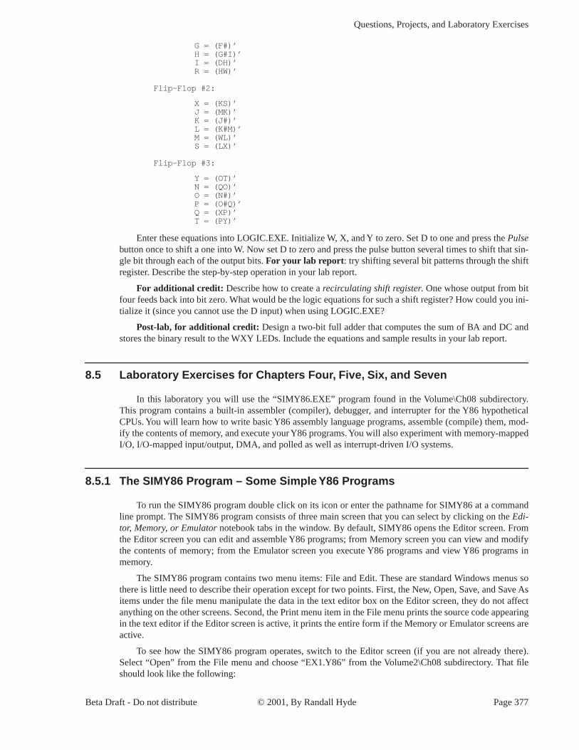
F = (IG)’G = (#F)’H = (G#I)’I = (DH)’X = (GY)’Y = (HX)’
Enter this set of equations and then test your flip-flop by entering different values on the D input switch and pressing the clock pulse button. Explain your results in your lab report.
In this exercise you will build a three-bit shift register using the logic equations for a true D flip-flop. To construct a shift register, you connect the outputs from each flip-flop to the input of the next flip-flop. The data input line provides the input to the first flip-flop, the last output line is the “carry out” of the circui Using a simple rectangle to represent a flip-flop and ignoring the Q’ output (since we don’t use it), the sche-matic for a four-bit shift register looks something like the following:
In the previous exercise you used six boolean expressions to define the D flip-flop. Therefore, we will need a total of 18 boolean expressions to implement a three-bit flip-flop. These expressions are
Flip-Flop #1:
W = (GR)’F = (IG)’
X
Y (=X')
A True D flip-flop
Clk (#)
D
F
G
H
I
W X Y
Clk (#)
A Three-bit Shift Register Built from D Flip-flops
Data In
D D DQ Q Q
Page 376 © 2001, By Randall Hyde Beta Draft - Do not distribute
Questions, Projects, and Laboratory Exercises
t
od
mande
ppearingare
ere).
G = (F#)’H = (G#I)’I = (DH)’R = (HW)’
Flip-Flop #2:
X = (KS)’J = (MK)’K = (J#)’L = (K#M)’M = (WL)’S = (LX)’
Flip-Flop #3:
Y = (OT)’N = (QO)’O = (N#)’P = (O#Q)’Q = (XP)’T = (PY)’
Enter these equations into LOGIC.EXE. Initialize W, X, and Y to zero. Set D to one and press the Pulsebutton once to shift a one into W. Now set D to zero and press the pulse button several times to shift that sin-gle bit through each of the output bits. For your lab report: try shifting several bit patterns through the shif register. Describe the step-by-step operation in your lab report.
For additional credit: Describe how to create a recirculating shift register. One whose output from bit four feeds back into bit zero. What would be the logic equations for such a shift register? How could you ini-tialize it (since you cannot use the D input) when using LOGIC.EXE?
Post-lab, for additional credit: Design a two-bit full adder that computes the sum of BA and DC and stores the binary result to the WXY LEDs. Include the equations and sample results in your lab report.
8.5 Laboratory Exercises for Chapters Four, Five, Six, and Seven
In this laboratory you will use the “SIMY86.EXE” program found in the Volume\Ch08 subdirectory. This program contains a built-in assembler (compiler), debugger, and interrupter for the Y86 hypothetical CPUs. You will learn how to write basic Y86 assembly language programs, assemble (compile) them, m-ify the contents of memory, and execute your Y86 programs. You will also experiment with memory-mapped I/O, I/O-mapped input/output, DMA, and polled as well as interrupt-driven I/O systems.
8.5.1 The SIMY86 Program – Some Simple Y86 Programs
To run the SIMY86 program double click on its icon or enter the pathname for SIMY86 at a com line prompt. The SIMY86 program consists of three main screen that you can select by clicking on thEdi-tor, Memory, or Emulator notebook tabs in the window. By default, SIMY86 opens the Editor screen. From the Editor screen you can edit and assemble Y86 programs; from Memory screen you can view and modify the contents of memory; from the Emulator screen you execute Y86 programs and view Y86 programs in memory.
The SIMY86 program contains two menu items: File and Edit. These are standard Windows menus so there is little need to describe their operation except for two points. First, the New, Open, Save, and Save As items under the file menu manipulate the data in the text editor box on the Editor screen, they do not affect anything on the other screens. Second, the Print menu item in the File menu prints the source code a in the text editor if the Editor screen is active, it prints the entire form if the Memory or Emulator screens active.
To see how the SIMY86 program operates, switch to the Editor screen (if you are not already th Select “Open” from the File menu and choose “EX1.Y86” from the Volume2\Ch08 subdirectory. That file should look like the following:
Beta Draft - Do not distribute © 2001, By Randall Hyde Page 377

Chapter Eight Volume Two
and
tarting ecifies efault, utines rt your Address ory.
boxes ecimal) his tells
6, and 7; int you ns 0000
ed for all you nge the nd 1002
ponding 1, and at at cell
ations ltiple of tarting 01. The
mem-7 cor-isables lues if
lls and ram’s u will
t vector ram exe-location
is no address es not .
mov( [1000], ax );mov( [1002], bx );add( bx, ax );sub( 1, ax );mov( ax, bx );add( ax, bx );add( bx, ax );halt;
This short code sequence adds the two values at location 1000 and 1002, subtracts one from their sum,multiplies the result by three ((ax + ax) + ax) = ax*3), leaving the result in AX and then it halts.
On the Editor screen you will see three objects: the editor window itself, a box that holds the “SAddress,” and an “Assemble” button. The “Starting Address” box holds a hexadecimal number that spwhere the assembler will store the machine code for the Y86 program you write with the editor. By dthis address is zero. About the only time you should change this is when writing interrupt service rosince the default reset address is zero. The “Assemble” button directs the SIMY86 program to conveassembly language source code into Y86 machine code and store the result beginning at the Startingin memory. Go ahead and press the “Assemble” button at this time to assemble this program to mem
Now press the “Memory” tab to select the memory screen. On this screen you will see a set of 64arranged as eight rows of eight boxes. To the left of these eight rows you will see a set of eight (hexadmemory addresses (by default, these are 0000, 0008, 0010, 0018, 0020, 0028, 0030, and 0038). Tyou that the first eight boxes at the top of the screen correspond to memory locations 0, 1, 2, 3, 4, 5, the second row of eight boxes correspond to locations 8, 9, A, B, C, D, E, and F; and so on. At this poshould be able to see the machine codes for the program you just assembled in memory locatiothrough 000D. The rest of memory will contain zeros.
The memory screen lets you look at and possibly modify 64 bytes of the total 64K memory providthe Y86 processors. If you want to look at some memory locations other than 0000 through 003F, need do is edit the first address (the one that currently contains zero). At this time you should chastarting address of the memory display to 1000 so you can modify the values at addresses 1000 a(remember, the program adds these two values together). Type the following values into the correscells: at address 1000 enter the value 34, at location 1001 the value 12, at location 1002 the value 0location 1003 the value 02. Note that if you type an illegal hexadecimal value, the system will turn thred and beep at you.
By typing an address in the memory display starting address cell, you can look at or modify localmost anywhere in memory. Note that if you enter a hexadecimal address that is not an even mueight, the SIMY86 program disable up to seven cells on the first row. For example, if you enter the saddress 1002, SIMY86 will disable the first two cells since they correspond to addresses 1000 and 10first active cell is 1002. Note the SIMY86 reserves memory locations FFF0 through FFFF for ory-mapped I/O. Therefore, it will not allow you to edit these locations. Addresses FFF0 through FFFrespond to read-only input ports (and you will be able to see the input values even though SIMY86 dthese cells). Locations FFF8 through FFFF are write-only output ports, SIMY86 displays garbage vayou look at these locations.
On the Memory page along with the memory value display/edit cells, there are two other entry cea button. The “Clear Memory” button clears memory by writing zeros throughout. Since your progobject code and initial values are currently in memory, you should not press this button. If you do, yoneed to reassemble your code and reenter the values for locations 1000 through 1003.
The other two items on the Memory screen let you set the interrupt vector address and the reseaddress. By default, the reset vector address contains zero. This means that the SIMY86 begins progcution at address zero whenever you reset the emulator. Since your program is currently sitting at zero in memory, you should not change the default reset address.
The “Interrupt Vector” value is FFFF by default. FFFF is a special value that tells SIMY86 “there interrupt service routine present in the system, so ignore all interrupts.” Any other value must be the of an ISR that SIMY86 will call whenever an interrupt occurs. Since the program you assembled dohave an interrupt service routine, you should leave the interrupt vector cell containing the value FFFF
Page 378 © 2001, By Randall Hyde Beta Draft - Do not distribute

Questions, Projects, and Laboratory Exercises
t,
nr
his stringtion
digits
is
f thes
lti-byte
he
dt
en a
areo
h
Finally, press the “Emulator” tab to look at the emulator screen. This screen is much busier than the other two. In the upper left hand corner of the screen is a data entry box with the label IP. This box holds the current value of the Y86 instruction pointer register. Whenever SIMY86 runs a program, it begins execution with the instruction at this address. Whenever you press the reset button (or enter SIMY86 for the first time), the IP register contains the value found in the reset vector. If this register does not contain zero at this poin press the reset button on the Emulator screen to reset the system.
Immediately below the IP value, the Emulator page disassembles the instruction found at the address i the IP register. This is the very next instruction that SIMY86 will execute when you press the “Run” o “Step” buttons. Note that SIMY86 does not obtain this instruction from the source code window on the Edi-tor screen. Instead, it decodes the opcode in memory (at the address found in IP) and generates t itself. Therefore, there may be minor differences between the instruction you wrote and the instruc SIMY86 displays on this page. Note that a disassembled instruction contains several numeric values in front of the actual instruction. The first (four-digit) value is the memory address of that instruction. The next pair of digits (or the next three pairs of digits) are the opcodes and possible instruction operand values. For exam-ple, the “mov( [1000], ax );” instruction’s machine code is C6 00 10 since these are the three sets of appearing at this point.
Below the current disassembled instruction, SIMY86 displays 15 instructions it disassembles. The start-ing address for this disassembly is not the value in the IP register. Instead, the value in the lower right hand corner of the screen specifies the starting disassembly address. The two little arrows next to the disassembly starting address let you quickly increment or decrement the disassembly starting address. Assuming the starting address is zero (change it to zero if it is not), press the down arrow. Note that this increments the starting address by one. Now look back at the disassembled listing. As you can see, pressing the down arrow has produced an interesting result. The first instruction (at address 0001) is “****”. The four asterisks indi-cate that this particular opcode is an illegal instruction opcode. The second instruction, at address 0002, “not( ax );”. Since the program you assembled did not contain an illegal opcode or a “not( ax );” instruction, you may be wondering where these instructions came from. However, note the starting address of the first instruction: 0001. This is the second byte of the first instruction in your program. In fact, the illegal instruc-tion (opcode=00) and the “not( ax );” instruction (opcode=10) are actually a disassembly o “mov( [1000], ax );” instruction’s two-byte operand. This should clearly demonstrate a problem with disa-sembly – it is possible to get “out of phase” by specify a starting address that is in the middle of a mu instruction. You will need to consider this when disassembling code.
In the middle of the Emulator screen there are several buttons: Run, Step, Halt, Interrupt, and Reset (t “Running” box is an annunciator, not a button). Pressing the Run button will cause the SIMY86 program to run the program (starting at the address in the IP register) at “full” speed. Pressing the Step button instructs SIMY86 to execute only the instruction that IP points at and then stop. The Halt button, which is only active while a program is running, will stop execution. Pressing the Interrupt button generates an interrupt an pressing the Reset button resets the system (and halts execution if a program is currently running). Note tha pressing the Reset button clears the Y86 registers to zero and loads the ip register with the value in the reset vector.
The “Running” annunciator is gray if SIMY86 is not currently running a program. It turns red wh program is actually running. You can use this annunciator as an easy way to tell if a program is running if the program is busy computing something (or is in an infinite loop) and there is no I/O to indicate program exe-cution.
The boxes with the AX, BX, CX, and DX labels let you modify the values of these registers while a pro-gram is not running (the entry cells are not enabled while a program is actually running). These cells also display the current values of the registers whenever a program stops or between instructions when you stepping through a program. Note that while a program is running the values in these cells are static and d not reflect their current values.
The “Less” and “Equal” check boxes denote the values of the less than and equal flags. The Y86 CMP instruction sets these flags depending on the result of the comparison. You can view these values while the program is not running. You can also initialize them to true or false by clicking on the appropriate box wit the mouse (while the program is not running).
Beta Draft - Do not distribute © 2001, By Randall Hyde Page 379

Chapter Eight Volume Two
port
nting
the
s of
eatedly
d
l
of you
In the middle section of the Emulator screen there are four “LEDs” and four “toggle switches.” Above each of these objects is a hexadecimal address denoting their memory-mapped I/O addresses. Writing a zero to a corresponding LED address turns that LED “off” (turns it white). Writing a one to a corresponding LED address turns that LED “on” (turns it red). Note that the LEDs only respond to bit zero of their addresses. These output devices ignore all other bits in the value written to these addresses.
The toggle switches provide four memory-mapped input devices. If you read the address above each switch SIMY86 will return a zero if the switch is off. SIMY86 will return a one if the switch is in the on position. You can toggle a switch by clicking on it with the mouse. Note that a little rectangle represe the switch turns red if the switch is in the “on” position.
The two columns on the right side of the Emulate screen (“Input” and “Output”) display input values read with the GET instruction and output values the PUT instruction prints.
For this first exercise, you will use the Step button to single step through each of the instructions in EX1.Y86 program. First, begin by pressing the Reset button3. Next, press the Step button once. Note that the values in the IP and AX registers change. The IP register value changes to 0003 since that is the addres the next instruction in memory, AX’S value changed to 1234 since that’s the value you placed at location 1000 when operating on the Memory screen. Single step through the remaining instructions (by rep pressing Step) until you get the “Halt Encountered” dialog box.
For your lab report: explain the results obtained after the execution of each instruction. Note that sin-gle-stepping through a program as you’ve done here is an excellent way to ensure that you fully understan how the program operates. As a general rule, you should always single-step through every program you write when testing it.
8.5.2 Simple I/O-Mapped Input/Output Operations
Go to the Editor screen and load the EX2.Y86 file into the editor. This program introduces some new concepts, so take a moment to study this code:
mov( 1000, bx );a: get;
mov( ax, [bx] );add( 2, bx );cmp( ax, 0 );jne a;
mov( bx, cx );mov( 1000, bx )mov( 0, ax );
b: add( [bx], ax );add( 2, bx );cmp( bx, cx );jb b;
put;halt;
The first thing to note are the two strings “a:” and “b:” appearing in column one of the listing. The SIMY86 assembler lets you specify up to 26 statement labels by specifying a single alphabetic character fo-lowed by a colon. Labels are generally the operand of a jump instruction of some sort. Therefore, the “jne a;” instruction above really says “jump if not equal to the statement prefaced with the ‘a:’ label” rather than say-ing “jump if not equal to location ten (0Ah) in memory.”
Using labels is much more convenient than figuring out the address of a target instruction manually, especially if the target instruction appears later in the code. The SIMY86 assembler computes the address these labels and substitutes the correct address for the operands of the jump instructions. Note thatcan
3. It is a good idea to get in the habit of pressing the Reset button before running or stepping through any program.
Page 380 © 2001, By Randall Hyde Beta Draft - Do not distribute

Questions, Projects, and Laboratory Exercises
t
t
ndan
ions
out
specify a numeric address in the operand field of a jump instruction. However, all numeric addresses mus begin with a decimal digit (even though they are hexadecimal values). If your target address would normally begin with a value in the range A through F, simply prepend a zero to the number. For example, if “jne a;” was supposed to mean “jump if not equal to location 0Ah” you would write the instruction as “jne 0a;”.
This program contains two loops. In the first loop, the program reads a sequence of values from the user until the user enters the value zero. This loop stores each word into successive memory locations starting a address 1000h. Remember, each word read by the user requires two bytes; this is why the loop adds two to bx on each iteration.
The second loop in this program scans through the input values and computes their sum. At the end of the loop, the code prints the sum to the output window using the PUT instruction.
For your lab report: single-step through this program and describe how each instruction works. Reset the Y86 and run this program at full speed. Enter several values and describe the result. Discuss the GET a PUT instructions. Describe why they do the equivalent of I/O-mapped input/output operations rather th memory-mapped input/output operations.
8.5.3 Memory Mapped I/O
From the Editor screen, load the EX3.Y86 program file. That program takes the following form (the comments were added here to make the operation of this program clearer):
a: mov( [fff0], ax );mov( [fff2], bx );
mov( ax, cx ); // Compute Sw0 and Sw1and( bx, cx );mov( cx, [fff8] );
mov( ax, cx ) ; // Computes Sw0 OR Sw1or( bx, cx );mov( cx, [fffa] );
mov( ax, cx ); // Computes Sw0 xor Sw1mov( bx, dx ); // XOR = AB’ + A’Bnot( cx );not( dx );and( bx, cx );and( ax, dx );or( dx, cx );mov( cx, [fffc] );
not( cx ); // Computes Sw0 = Sw1mov( cx, [fffe] ); // Note: equals is not xor
mov( [fff4], ax ); // Read the third switch.cmp( ax, 0 ); // See if it’s on.je a; // Repeat this program while it’s on.halt;
Locations $FFF0, $FFF2, and $FFF4 correspond to the first three toggle switches on the Execution page. These are memory-mapped I/O devices that put a zero or one into the corresponding memory locat depending upon whether the toggle switch is in the on or off state. Locations $FFF8, $FFFA, $FFFC, and $FFFE correspond to the four LEDs. Writing a zero to these locations turns the corresponding LED off, writ-ing a one turns it on.
This program computes the logical AND, OR, XOR, and XNOR (not XOR) functions for the values read from the first two toggle switches. This program displays the results of these functions on the four -
Beta Draft - Do not distribute © 2001, By Randall Hyde Page 381

Chapter Eight Volume Two
of
ress
bing0.
e
put LEDs. This program reads the value of the third toggle switch to determine when to quit. When the third toggle switch is in the on position, the program will stop.
For your lab report: run this program and cycle through the four possible combinations of on and f for the first two switches. Include the results in your lab report.
8.5.4 DMA Exercises
In this exercise you will start a program running (EX4.Y86) that examines and operates on values found in memory. Then you will switch to the Memory screen and modify values in memory (that is, you will directly access memory while the program continues to run), thus simulating a peripheral device that uses DMA.
The EX4.Y86 program begins by setting memory location $1000 to zero. Then it loops until one of two conditions is met – either the user toggles the FFF0 switch or the user changes the value in memory location $1000. Toggling the FFF0 switch terminates the program. Changing the value in memory location $1000 transfers control to a section of the program that adds together n words, where n is the new value in memory location $1000. The program sums the words appearing in contiguous memory locations starting at add $1002. The actual program looks like the following:
d: mov( 0, cx ); // Clear location $1000 before we begin testing it.mov( cx, [1000] );
// The following loop checks to see if memory location $1000 changes or if// the FFF0 switch is in the on position.
a: mov( [1000], cx ); // Check to see if location $1000cmp( cx, 0 ); // Changes. Jump to the section thatjne c; // sums the values if it does.
mov( [fff0], ax ); // If location $1000 still contains zero,cmp( ax, 0 ); // read the FFF0 switch and see if it isje a; // of. If so, loop back. If the switchhalt; // is on, quit the program.
// The following code sums up the “cx” contiguous words of memory starting at// memory location $1002. After it sums up these values, it prints their sum.
c: mov( 1002, bx ); // Initialize BX to point at data array.mov( 0, ax ); // Initialize the sum.
b: add( [bx], ax ); // Sum in the next array value.add( 2, bx ); // Point BX at the next item in the array.sub( 1, cx ); // Decrement the element count.cmp( cx, 0 ); // Test to see if we’ve added up all thejne b; // values in the array.
put; // Print the sum and start over.jmp d;
Load this program into SIMY86 and assemble it. Switch to the Emulate screen, press the Resetutton, make sure the FFF0 switch is in the off position, and then run the program. Once the program is runn switch to the memory screen by pressing the Memory tab. Change the starting display address to $100 Change the value at location $1000 to 5. Switch back to the emulator screen. Assuming memory locations $1002 through $100B all contain zero, the program should display a zero in the output column.
Switch back to the memory page. What does location $1000 now contain? Change the L.O. bytes of th words at address $1002, $1004, and $1006 to 1, 2, and 3, respectively. Change the value in location $1000 to three. Switch to the Emulator page. Describe the output in your lab report. Try entering other values into memory. Toggle the FFF0 switch when you want to quit running this program.
Page 382 © 2001, By Randall Hyde Beta Draft - Do not distribute

Questions, Projects, and Laboratory Exercises
2.
rou
e
e on
s
will
heishe inter
ther
the
For your lab report: explain how this program uses DMA to provide program input. Run several tests with different values in location $1000 and different values in the data array starting at location $100 Include the results in your report.
For additional credit: Store the value $12 into memory location $1000. Explain why the program prints two values instead of just one value.
8.5.5 Interrupt Driven I/O Exercises
In this exercise you will load two programs into memory: a main program and an interrupt service -tine. This exercise demonstrates the use of interrupts and an interrupt service routine.
The main program (EX5a.Y86) will constantly compare memory locations $1000 and $1002. If thy are not equal, the main program will print the value of location $1000 and then copy this value to location $1002 and repeat this process. The main program repeats this loop until the user toggles switch FFF0 to th position. The code for the main program is the following:
a: mov( [1000], ax ); // Fetch the data at location $1000 andcmp( ax, [1002] ); // see if it is the same as locationje b; // $1002. If so, check the FFF0 switch.put; // If the two values are different, printmov( ax, [1002] ); // $1000’s value and make them the same.
b: mov( [fff0], ax ); // Test the FFF0 switch to see if wecmp( ax, 0 ); // should quit this program.je a;halt;
The interrupt service routine (EX5b.Y86) sits at location $100 in memory. Whenever an interrupt occurs, this ISR simply increments the value at location $1000 by loading this value into AX, adding one to the value in AX, and then storing this value back to location $1000. After these instructions, the ISR return to the main program. The interrupt service routine contains the following code:
mov( ax, [1004] ); // The ISR must preserve any register it uses!mov( [1000], ax ); // Increment the value at location $1000 by oneadd( 1, ax ); // and return to the interrupted code.mov( ax, [1000] );mov( [1004], ax ); // Restore AX’s original value.iret; // Return from the interrupt.
You must load and assemble both files before attempting to run the main program. Begin by loading the main program (EX5a.Y86) into memory and assemble it at address zero. Then load the ISR (EX5b.Y86) into memory, set the Starting Address to 100, and then assemble your code. Warning: if you forget to change the starting address you will wipe out your main program when you assemble the ISR. If this happens, you need to repeat this procedure from the beginning.
After assembling the code, the next step is to set the interrupt vector so that it contains the address of t ISR. To do this, switch to the Memory screen. The interrupt vector cell should currently contain $FFFF (th value indicates that interrupts are disabled). Change this to $100 so that it contains the address of t-rupt service routine. This also enables the interrupt system.
Finally, switch to the Emulator screen, make sure the FFF0 toggle switch is in the off position, reset the program, and start it running. Normally, nothing will happen. Now press the interrupt button and observe the results.
For your lab report: describe the output of the program whenever you press the interrupt button. Explain all the steps you would need to follow to place the interrupt service routine at address $2000 ra than $100.
For additional credit: write your own interrupt service routine that does something simple. Run main program and press the interrupt button to test your code. Verify that your ISR works properly.
Beta Draft - Do not distribute © 2001, By Randall Hyde Page 383

Chapter Eight Volume Two
r
8.5.6 Machine Language Programming & Instruction Encoding Exercises
To this point you have been creating machine language programs with SIMY86’s built-in assembler. An assembler is a program that translates an ASCII source file containing textual representations of a program into the actual machine code. The assembler program saves you a considerable amount of work by translat-ing human readable instructions into machine code. Although tedious, you can perform this translation you-self. In this exercise you will create some very short machine language programs by encoding the instructions and entering their hexadecimal opcodes into memory on the memory screen.
Using the instruction encodings found in Figure 5.3, Figure 5.4, Figure 5.5, and Figure 5.6, write the hexadecimal values for the opcodes beside each of the following instructions:
Page 384 © 2001, By Randall Hyde Beta Draft - Do not distribute

Questions, Projects, and Laboratory Exercises
zerou
m and
Figure 8.1 A Simple Program to Convert to Machine Code
You can assume that the program starts at address zero and, therefore, label a will be at address $0003 sincethe “mov( 0, cx );” instruction is three bytes long.
For your lab report: enter the hexadecimal opcodes and operands into memory starting at location using the Memory editor screen. Dump these values and include them in your lab report. Switch to the Em-lator screen and disassemble the code starting at address zero. Verify that this code is the same as the asse-bly code above. Print a copy of the disassembled code and include it in your lab report. Run the program verify that it works properly.
mov( 0, cx );
a: get;
put;
add( ax, ax );
put;
add( ax, ax );
put;
add( ax, ax );
put;
add( 1, cx );
cmp( cx, 4 );
jb a;
halt;
Binary Opcode Hex Operand
Beta Draft - Do not distribute © 2001, By Randall Hyde Page 385

Chapter Eight Volume Two
n e
ify
at aren
8.5.7 Self Modifying Code Exercises
In the previous laboratory exercise, you discovered that the system doesn’t really differentiate data and instructions in memory. You were able to enter hexadecimal data and the Y86 processor treats it as a sequence of executable instructions. It is also possible for a program to store data into memory and thexe-cute it. A program is self-modifying if it creates or modifies some of the instructions it executes.
Consider the following Y86 program (EX6.Y86):
sub( ax, ax ); // Trick: sets AX to zero.mov( ax, [100] );
a: mov( [100], ax );cmp( ax, 0 );je b;halt;
b: mov( c6, ax );mov( ax, [100] );mov( 710, ax );mov( ax, [102] );mov( a6a0, ax );mov( ax, [104] );mov( 1000, ax );mov( ax, [106] );mov( 8007, ax );mov( ax, [108] );mov( e6, ax );mov( ax, [10a] );mov( e10, ax );mov( ax, [10c] );mov( 4, ax );mov( ax, [10e] ));jmp 100;
This program writes the following code to location $100 and then executes it:
mov( [1000], ax );put;add( ax, ax );add( [1000], ax );put;sub( ax, ax );mov( ax, [1000] );put;sub( ax, ax );mov( ax, [1000] );jmp 0004; // $0004 is the address of the a: label.
For your lab report: execute the EX7.Y86 program and verify that it generates the above code at loca-tion 100.
Although this program demonstrates the principle of self-modifying code, it hardly does anything use-ful. As a general rule, one would not use self-modifying code in the manner above, where one segment writes some sequence of instructions and then executes them. Instead, most programs that use self-mod-ing code only modify existing instructions and often only the operands of those instructions.
Self-modifying code is rarely found in modern assembly language programs. Programs th self-modifying are hard to read and understand, difficult to debug, and often unstable. Programmers ofte resort to self-modifying code when the CPU’s architecture lacks sufficient power to achieve a desired goal. The later Intel 80x86 processors do not lack for instructions or addressing modes, so it is very rare to find
Page 386 © 2001, By Randall Hyde Beta Draft - Do not distribute

Questions, Projects, and Laboratory Exercises
.
follo
she JMPcode (the
ulator
80x86 programs that use self-modifying code4. The Y86 processors, however, have a very weak instruction set, so there are actually a couple of instances where self-modifying code may prove useful.
A good example of an architectural deficiency where the Y86 is lacking is with respect to subroutines The Y86 instruction set does not provide any (direct) way to call and return from a subroutine. However, you can easily simulate a call and return using the JMP instruction and self-modifying code. Consider the w-ing Y86 “subroutine” that sits at location $100 in memory:
// Integer to Binary converter.// Expects an unsigned integer value in AX.// Converts this to a string of zeros and ones storing this string of// values into memory starting at location $1000.
mov( 1000, ax ); // Starting address of string.mov( 10, cx ); // 16 ($10) digits in a word.
a: mov( 0, dx ); // Assume current bit is zero.cmp( ax, 8000 ); // See if AX’s H.O. bit is zero or one.jb b; // Branch if AX’x H.O. bit is zero.mov( 1, dx ); // AX’s H.O. bit is one, set that here.
b: mov( dx, [bx] ); // Store zero or one to next location.add( 1, bx ); // Bump BX to point at next byte in memory.add( ax, ax ); // AX = AX *2 (shift left operation).sub( 1, cx ); // Count off 16 bits.cmp( cx, 0 ); // Repeat 16 times.ja a;jmp 0; // Return to caller via self-modifying code.
The only instruction that a program will modify in this subroutine is the very last JMP instruction. This jump instruction must transfer control to the first instruction beyond the JMP in the calling code that tran-fers control to this subroutine; that is, the caller must store the return address into the operand of t instruction in the code above. As it turns out, the JMP instruction is at address $120 (assuming the above starts at location $100). Therefore, the caller must store the return address into location $121 operand of the JMP instruction). The following sample “main” program makes three calls to the “subrou-tine” above:
mov( c, ax ); // Address of the BRK instruction below.mov( ax, [121] ); // Store into JMP as return address.mov( 1234, ax ); // Convert $1234 to binary.jmp 100; // “Call” the subroutine above.brk; // Pause to let the user example bytes at $1000.
mov( 19, ax ); // Address of the BRK instruction below.mov( ax, [121] ); // Store into JMP as return address.mov( fdeb, ax ); // Convert $FDEB to binary.jmp 100; // “Call” the subroutine above.brk; // Pause to let the user example bytes at $1000.
mov( 16, ax ); // Address of the BRK instruction below.mov( ax, [121] ); // Store into JMP as return address.mov( 2345, ax ); // Convert $2345 to binary.jmp 100; // “Call” the subroutine above.brk; // Pause to let the user example bytes at $1000.
halt;
Load the subroutine (EX7s.Y86) into SIMY86 and assemble it starting at location $100. Next, load the main program (EX7m.Y86) into memory and assemble it starting at location zero. Switch to the Em screen and verify that all the return addresses ($c, $19, and $26) are correct. Also verify that the return
4. Many viruses and copy protection programs use self modifying code to make it difficult to detect or bypass them.
Beta Draft - Do not distribute © 2001, By Randall Hyde Page 387
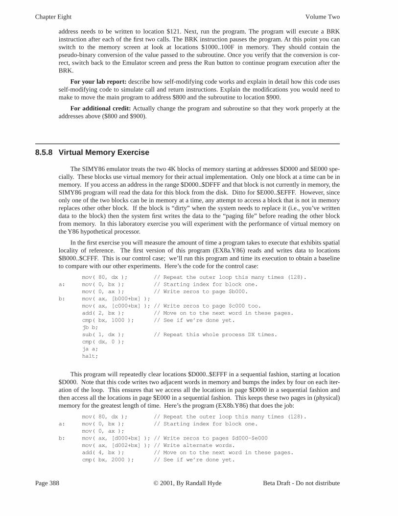
Chapter Eight Volume Two
spe be in
ory
ry
n
ons
address needs to be written to location $121. Next, run the program. The program will execute a BRK instruction after each of the first two calls. The BRK instruction pauses the program. At this point you can switch to the memory screen at look at locations $1000..100F in memory. They should contain the pseudo-binary conversion of the value passed to the subroutine. Once you verify that the conversion is cor-rect, switch back to the Emulator screen and press the Run button to continue program execution after the BRK.
For your lab report: describe how self-modifying code works and explain in detail how this code uses self-modifying code to simulate call and return instructions. Explain the modifications you would need to make to move the main program to address $800 and the subroutine to location $900.
For additional credit: Actually change the program and subroutine so that they work properly at the addresses above ($800 and $900).
8.5.8 Virtual Memory Exercise
The SIMY86 emulator treats the two 4K blocks of memory starting at addresses $D000 and $E000 -cially. These blocks use virtual memory for their actual implementation. Only one block at a time can memory. If you access an address in the range $D000..$DFFF and that block is not currently in mem, the SIMY86 program will read the data for this block from the disk. Ditto for $E000..$EFFF. However, since only one of the two blocks can be in memory at a time, any attempt to access a block that is not in memo replaces other other block. If the block is “dirty” when the system needs to replace it (i.e., you’ve written data to the block) then the system first writes the data to the “paging file” before reading the other block from memory. In this laboratory exercise you will experiment with the performance of virtual memory o the Y86 hypothetical processor.
In the first exercise you will measure the amount of time a program takes to execute that exhibits spatial locality of reference. The first version of this program (EX8a.Y86) reads and writes data to locati $B000..$CFFF. This is our control case; we’ll run this program and time its execution to obtain a baseline to compare with our other experiments. Here’s the code for the control case:
mov( 80, dx ); // Repeat the outer loop this many times (128).a: mov( 0, bx ); // Starting index for block one.
mov( 0, ax ); // Write zeros to page $b000.b: mov( ax, [b000+bx] );
mov( ax, [c000+bx] ); // Write zeros to page $c000 too.add( 2, bx ); // Move on to the next word in these pages.cmp( bx, 1000 ); // See if we’re done yet.jb b;sub( 1, dx ); // Repeat this whole process DX times.cmp( dx, 0 );ja a;halt;
This program will repeatedly clear locations $D000..$EFFF in a sequential fashion, starting at location $D000. Note that this code writes two adjacent words in memory and bumps the index by four on each iter-ation of the loop. This ensures that we access all the locations in page $D000 in a sequential fashion and then access all the locations in page $E000 in a sequential fashion. This keeps these two pages in (physical) memory for the greatest length of time. Here’s the program (EX8b.Y86) that does the job:
mov( 80, dx ); // Repeat the outer loop this many times (128).a: mov( 0, bx ); // Starting index for block one.
mov( 0, ax ); b: mov( ax, [d000+bx] ); // Write zeros to pages $d000-$e000
mov( ax, [d002+bx] ); // Write alternate words.add( 4, bx ); // Move on to the next word in these pages.cmp( bx, 2000 ); // See if we’re done yet.
Page 388 © 2001, By Randall Hyde Beta Draft - Do not distribute

Questions, Projects, and Laboratory Exercises
eeen the
ea
e
youral
,
jb b;sub( 1, dx ); // Repeat this whole process DX times.cmp( dx, 0 );ja a;halt;
Now load the following program into memory (EX8c.Y86) and repeat the timing of this code. This code also accesses pages $D000 and $E000 but the access pattern is different. Rather than accessing all th locations in page $D000 and then accessing all the locations in $E000, this code “ping-pongs” betw two pages, accessing a word in one page and then accessing a word in the second page. This forces the vir-tual memory subsystem to continuously reload the two pages on each access (i.e., thrashing occurs). M-sure the amount of time it takes to execute. Record the time for your lab report. Note a major difference between this program and the previous two: the previous programs executed the outer loop 128 times whil the following program only executes eight times. Be sure to multiply the running time of the following pro-gram by 16 to obtain a fair comparison of the running time of this program.
mov( 8, dx ); // Repeat the outer loop this many times (8).a: mov( 0, bx ); // Starting index for block one.
mov( 0, ax ); // Write zeros to page $d000.b: mov( ax, [d000+bx] );
mov( ax, [e000++bx] ); // Write zeros to page $e000 too.add( 2, bx ); // Move on to the next word in these pages.cmp( bx, 1000 ); // See if we’re done yet.jb b;sub( 1, dx ); // Repeat this whole process DX times.cmp( dx, 0 );ja a;halt;
For your lab report: Measure the execution time of these three programs. Present the results in lab report. In light of this experiment, describe how you might restructure a real program running in virtu memory to obtain the best performance.
For additional credit: Explain, based on your knowledge of the hardware needed to implement paging why there is a difference in execution time between the first and second programs in this experiment.
Beta Draft - Do not distribute © 2001, By Randall Hyde Page 389

Chapter Eight Volume Two
Page 390 © 2001, By Randall Hyde Beta Draft - Do not distribute