questions? 08457 089 009 -...
TRANSCRIPT

USER'S MANUALSerial Number
Decal
Model No. WETL13606.0Serial No.
CAUTIONRead all precautions and instruc-tions in this manual before usingthis equipment. Save this manualfor future reference.
QUESTIONS?As a manufacturer, we are com-mitted to providing completecustomer satisfaction. If youhave questions, or if there aremissing or damaged parts,please call:
or write:ICON Health & Fitness, Ltd.Customer Service DepartmentUnit 4Revie Road Industrial EstateRevie RoadBeestonLeeds, LS118JGUK
email: [email protected]
08457 089 009

TABLE OF CONTENTS
IMPORTANT PRECAUTIONS . . . . . . . . . . . . . . . . . . . . . . . . . . . . . . . . . . . . . . . . . . . . . . . . . . . . . . . . . . . . . . . . .3BEFORE YOU BEGIN . . . . . . . . . . . . . . . . . . . . . . . . . . . . . . . . . . . . . . . . . . . . . . . . . . . . . . . . . . . . . . . . . . . . . . .5ASSEMBLY . . . . . . . . . . . . . . . . . . . . . . . . . . . . . . . . . . . . . . . . . . . . . . . . . . . . . . . . . . . . . . . . . . . . . . . . . . . . . . .6OPERATION AND ADJUSTMENT . . . . . . . . . . . . . . . . . . . . . . . . . . . . . . . . . . . . . . . . . . . . . . . . . . . . . . . . . . . .10HOW TO FOLD AND MOVE THE TREADMILL . . . . . . . . . . . . . . . . . . . . . . . . . . . . . . . . . . . . . . . . . . . . . . . . . .15MAINTENANCE AND TROUBLESHOOTING . . . . . . . . . . . . . . . . . . . . . . . . . . . . . . . . . . . . . . . . . . . . . . . . . . . .17CONDITIONING GUIDELINES . . . . . . . . . . . . . . . . . . . . . . . . . . . . . . . . . . . . . . . . . . . . . . . . . . . . . . . . . . . . . . .19ORDERING REPLACEMENT PARTS . . . . . . . . . . . . . . . . . . . . . . . . . . . . . . . . . . . . . . . . . . . . . . . . . .Back Cover
Note: A PART IDENTIFICATION CHART, an EXPLODED DRAWING, and a PART LIST are attached in thecenter of this manual.
WESLO is a registered trademark of ICON IP, Inc.
2

3
WARNING: To reduce the risk of burns, fire, electric shock, or injury to persons, read thefollowing important precautions and information before operating the treadmill.
IMPORTANT PRECAUTIONS
1. It is the responsibility of the owner to ensurethat all users of this treadmill are adequatelyinformed of all warnings and precautions.
2. Use the treadmill only as described.
3. Place the treadmill on a level surface, with atleast 2.5 m (8 ft.) of clearance behind it and 0.5 m (2 ft.) on each side. Do not place thetreadmill on a surface that blocks any airopenings. To protect the floor or carpet fromdamage, place a mat under the treadmill.
4. Keep the treadmill indoors, away from mois-ture and dust. Do not put the treadmill in agarage or covered patio, or near water.
5. Do not operate the treadmill where aerosolproducts are used or where oxygen is beingadministered.
6. Keep children under the age of 12 and petsaway from the treadmill at all times.
7. The treadmill should be used only by personsweighing 115 kg (250 lbs.) or less.
8. Never allow more than one person on thetreadmill at a time.
9. Wear appropriate exercise clothes whenusing the treadmill. Do not wear loose clothesthat could become caught in the treadmill.Athletic support clothes are recommended forboth men and women. Always wear athleticshoes; never use the treadmill with bare feet,wearing only stockings, or in sandals.
10. When connecting the power cord (see page10), plug the power cord into an earthed cir-cuit. No other appliance should be on thesame circuit. When replacing the fuse, anASTA approved BS1362 type should be fittedto the fuse carrier. A 13 amp fuse should beused.
11. If an extension cord is needed, use only a 3-conductor, 1mm2 (14-gauge) cord that is nolonger than 1.5 m (5 ft.).
12. Keep the power cord away from heated sur-faces.
13. Never move the walking belt while the poweris turned off. Do not operate the treadmill ifthe power cord or plug is damaged, or if thetreadmill is not working properly. (See MAIN-TENANCE AND TROUBLESHOOTING on page17 if the treadmill is not working properly.)
14. Read, understand, and test the emergencystop procedure before using the treadmill (seeOPERATION AND ADJUSTMENT on page 10).
15. Never start the treadmill while you are stand-ing on the walking belt. Always hold thehandrails while using the treadmill.
16. The treadmill is capable of high speeds.Adjust the speed in small increments to avoidsudden jumps in speed.
17. Never leave the treadmill unattended while it isrunning. Always remove the key and unplugthe power cord when the treadmill is not in use.
18. Do not attempt to raise, lower, or move thetreadmill until it is properly assembled. (SeeASSEMBLY on page 6, and HOW TO FOLDAND MOVE THE TREADMILL on page 15.)You must be able to safely lift 20 kg (45 lbs.) toraise, lower, or move the treadmill.
19. When folding or moving the treadmill, makesure that the frame is securely held by thelatch pin.
20. Do not change the incline of the treadmill byplacing objects under the treadmill.

4
The decal shown at the right has been placed on thetreadmill. If the decal is missing, or if it is not legible,call the toll-free telephone number on the front cover ofthis manual and order a free replacement decal. Applythe decal in the location shown. Note: The decal is notshown at actual size.
21. Inspect and properly tighten all parts of thetreadmill regularly.
22. Never drop or insert any object into any opening.
23. DANGER: Always unplug the powercord immediately after use, before cleaningthe treadmill, and before performing the main-tenance and adjustment procedures de-
scribed in this manual. Never remove themotor hood unless instructed to do so by anauthorized service representative. Servicingother than the procedures in this manualshould be performed by an authorized servicerepresentative only.
24. This treadmill is intended for in-home useonly. Do not use this treadmill in any commer-cial, rental, or institutional setting.
WARNING: Before beginning this or any exercise program, consult your physician. Thisis especially important for persons over the age of 35 or persons with pre-existing health problems.Read all instructions before using. ICON assumes no responsibility for personal injury or propertydamage sustained by or through the use of this product.
SAVE THESE INSTRUCTIONS

5
Thank you for selecting the new WESLO® CADENCE55 treadmill. The CADENCE 55 treadmill combines ad-vanced technology with innovative design to makeyour workouts at home more effective and enjoyable.And when you’re not exercising, the CADENCE 55treadmill can be folded up, requiring less than half thefloor space of other treadmills.
For your benefit, read this manual carefully beforeusing the treadmill. If you have questions after read-
ing this manual, please see the front cover of this man-ual. To help us assist you, please note the productmodel number and serial number before contacting us.The model number of the treadmill is WETL13606.0.The serial number can be found on a decal attached tothe treadmill (see the front cover of this manual for thelocation).
Before reading further, please familiarise yourself withthe parts that are labelled in the drawing below.
BEFORE YOU BEGIN
Handrail
Storage Latch
Console
Key/Clip
Circuit Breaker
Incline Leg/Pin
Walking Belt
Hood
Wheel
Foot Rail
Rear Roller Adjustment Bolts
Water Bottle Holder(Bottle not included)
RIGHT SIDE
On/Off Switch

6
ASSEMBLYAssembly requires two persons. Set the treadmill in a cleared area and remove all packing materials; do notdispose of the packing materials until assembly is completed. Note: The underside of the treadmill walkingbelt is coated with high-performance lubricant. During shipping, a small amount of lubricant may be transferred tothe top of the walking belt or the shipping carton. This does not affect treadmill performance. If there is lubricanton top of the walking belt, simply wipe off the lubricant with a soft cloth and a mild, non-abrasive cleaner.
Assembly requires the hex key and your own phillips screwdriver , two spanners , and wire cutters .
Note: To identify small parts used during assembly, see the PART IDENTIFICATION CHART in the center ofthis manual. Some parts may be preassembled.
1. Have a second person hold the Base (54) in the positionshown.
Identify the Left Upright (55) (the Right Upright [56] has alarge hole near the lower end).
Hold the Left Upright (55) so the bend is in the posi-tion shown. Insert two Upright Bolts (2) into thebracket on the Left Upright. Attach the Left Upright tothe Base (54) with the Upright Bolts and two Upright Nuts(16). Do not tighten the Upright Nuts yet.
Attach the Right Upright (56) to the Base (54) in the sameway.
2. Slide the two Wheel Housings (64) onto the Base (54).Attach each Wheel Housing with two Wheel Housing Bolts(6), two Wheel Housing Washers (11), and two WheelHousing Nuts (15).
54
55
56
16
1
2
2 16
2
54
LargeHole
6 11
64 15
116
64 15
Bend

7
3. With the help of a second person, raise the Uprights(55, 56) so the Base (54) is flat on the floor as shown.
Position the front of the treadmill Frame (53) between theUprights (55, 56) as shown. Next, locate the long wire in-side of the lower end of the Right Upright (see the insetdrawing). Secure the end of the wire to the end of theWire Harness (97) using the included plastic tie. Then,pull the other end of the wire until the end of the WireHarness is extending from the indicated hole in the upperend of the Right Upright.
Have a second person lift and hold the front end of theFrame (53). Hold a Frame Spacer (111) between the RightUpright (56) and the Frame. Attach the Right Upright andthe Frame Spacer to the Frame with a Frame Bolt (1), aFrame Washer (14), and a Frame Star Washer (9).
Repeat this step on the left side of the treadmill.9
111
54
14
1
56
53
LargeHole
Hole3
55
4. Have a second person raise and hold the treadmillFrame (not shown).
Identify the Gas Spring (101). Note that the Gas Springhas a cylinder end and a piston end. See the two smallinset drawings. Locate the Spring Clip (52) in the cylinderend of the Gas Spring. Using your fingernail or the end ofa screwdriver, press on the end of the Spring Clip toloosen it, rotate the Spring Clip, and then pull the SpringClip out of the Gas Spring. Be careful to avoid losingthe Spring Clip. Note: Extra Spring Clips are included.
Next, hold the cylinder end of the Gas Spring (101) nearthe bracket in the center of the Base (54). Press the endof the Gas Spring as far as possible onto the ball on thebracket.
See drawing 4a. Insert the Spring Clip (52) into the twoindicated small holes in the end of the Gas Spring (101).Then, rotate the Spring Clip until it clips onto the GasSpring.
52
101
101
54
54
Holes
52
4a
Bracket
Cylinder
Piston
Bracket
52
52
4
97 56
Tie
Wire
97

8
7. Hold the Console Assembly (90) near the Right Upright(56). Touch the Right Handrail to discharge any static.
Insert the end of the Wire Harness (97) into the hole inthe bottom of the Right Handrail (57) and out of the largehole in the side. Next, Insert the end of the Wire Harnessthrough the two looped plastic ties.
Press the end of the Wire Harness (97) into the indicatedconnector on the back of the Console Assembly (90).The end of the Wire Harness should slide easily intothe connector and snap into place. If it does not, turnthe end of the Wire Harness and try again. IF THE CON-NECTOR IS NOT INSERTED PROPERLY, THE CON-SOLE MAY BE DAMAGED WHEN THE POWER ISTURNED ON.
PlasticTies
Connector
90
57
97
56
6. Turn the Console Assembly (90) face-down. Be carefulnot to scratch the face of the Console Assembly.
Identify the Right Handrail (57), which has a large hole inone side.
Attach the Right Handrail (57) to the Console Assembly(90) with two Console Screws (4), a Crossbar Screw (5),and a Crossbar Star Washer (12).
Attach the Left Handrail (not shown) in the same way.
12
90
4
Large Hole
5
57
7
6
97
5. Pivot the piston end of the Gas Spring (101) up to theposition shown. Remove the Spring Clip (52) from thepiston end of the Gas Spring.
Next, align with piston end of the Gas Spring (101) withthe bracket in the center of the Frame (53). Press theend of the Gas Spring onto the ball on the bracket. Note:It may be necessary to pivot the Frame forward or back-ward slightly to align the end of the Gas Spring with theball.
See drawing 5a. Insert the Spring Clip (52) into the twoindicated small holes in the Gas Spring (101). Then, ro-tate the Spring Clip until it clips onto the Gas Spring.
With the help of a second person, lower the Frame (53) tothe floor.
101
52101
52
53
53
Bracket
Bracket
5a
5

9
10. Carefully lower the Handrails (57, 58) to the floor. Centerthe Frame (53) between the Handrails, and tighten thefour Upright Bolts (2). Then, raise the Handrails back tothe vertical position.
See drawing 10a. Attach the Latch Assembly (108) to theLeft Upright (55) with two Latch Screws (7). Make surethat the Latch Assembly is oriented as shown.
See HOW TO CHANGE THE INCLINE OF THE TREAD-MILL on page 14. Adjust the incline of the treadmill asdesired.
11. Make sure that all parts are properly tightened be-fore you use the treadmill. Note: Extra hardware maybe included. Keep the included hex keys in a secureplace; the large hex key is used to adjust the walkingbelt (see page 18). To protect the floor or carpet, placea mat under the treadmill.
108
55
7
9. Set the Console Assembly (90) on the Right Upright (56)and the Left Upright (not shown). Next, start fourHandrail Bolts (3) with four Handrail Washers (13) andfour Handrail Star Washers (10) (only two of each areshown) into the Right Upright and the Left Upright.Then, tighten all four Handrail Bolts.
Insert the slack in the Wire Harness (97) down into theRight Upright (56).
Attach the Console Back (92) to the Console Assembly(90) with four Console Back Screws (7). Make sure thatthe Wire Harness (97) is in the indicated slot in theConsole Back and that no wires are pinched.
90
56
7
710
97
Slot
13
3
92
9
10
10a
57, 58
53 2
8. Insert the slack in the Wire Harness (97) down into theRight Upright (56). Then, tighten the two plastic tiesaround the Wire Harness, and cut off the ends of the plas-tic ties.
97 PlasticTies
56
8

10
THE PRE-LUBRICATED WALKING BELT
Your treadmill features a walking belt coated with high-performance lubricant. IMPORTANT: Never apply sili-cone spray or other substances to the walking belt or the walking platform. Such substances will deterio-rate the walking belt and cause excessive wear.
HOW TO PLUG IN THE POWER CORD
This product must be earthed. If it should malfunction or breakdown, earthing provides a path of least resistance for electric cur-rent to reduce the risk of electric shock. This product is equippedwith a power cord having an equipment-earthing conductor and anearthing plug. Important: If the power cord is damaged, it mustbe replaced with a manufacturer-recommended power cord.
See drawing 1. Plug the indicated end of the power cord into thesocket on the treadmill.
See drawing 2. Press the pins on the power cord into the metal clipsin the adapter as shown. Close the adapter cover over the end of thepower cord and tighten the screw in the adapter. Important: Makesure that the adapter cover is secure and the screw has beentightened before using the power cord.
See drawing 3. Plug the power cord into an appropriate outlet that isproperly installed and earthed in accordance with all local codes andordinances. Important: The treadmill is not compatible withGFCI-equipped outlets.
DANGER: Improper connection of the equipment-earthing conductor can result in an in-creased risk of electric shock. Check with a qualified electrician or serviceman if you are in doubt asto whether the product is properly earthed. Do not modify the plug provided with the product—if it willnot fit the outlet, have a proper outlet installed by a qualified electrician.
Socket on treadmill
Metal Clips
1
2
Pins
Screw
Adapter
Outlet3
AdapterCover
OPERATION AND ADJUSTMENT

11
FEATURES OF THE CONSOLE
The treadmill console offers a selection of featuresdesigned to make your workouts more effective.
When the manual mode of the console is selected, thespeed of the treadmill can be changed with the touchof a button. As you exercise, the displays will providecontinuous exercise feedback.
The console also offers four speed programs. Eachprogram automatically controls the speed of the tread-mill as it guides you through an effective workout.
Note: If there is a sheet of clear plastic on the con-sole, peel off the plastic. To prevent damage to thewalking platform, always wear clean athletic shoeswhile using the treadmill. During the first few min-utes that the treadmill is used, inspect the align-ment of the walking belt, and center the walkingbelt if necessary (see page 18).
HOW TO TURN ON THE POWER
Plug in the power cord (seepage 10). Next, locate theon/off switch on the treadmillframe near the right upright.Make sure that the switch isin the “on” position.
Next, stand on the foot rails of the treadmill. Find theclip attached to the key (see the drawing above), andslide the clip onto the waistband of your clothes. Then,insert the key into the console. After a moment, thetrack and the three displays will light. Important: In anemergency situation, the key can be pulled fromthe console, causing the walking belt to slow to astop. Test the clip by carefully taking a few stepsbackward; if the key is not pulled from the console,adjust the position of the clip.
CONSOLE DIAGRAM
OnPosition
KeyClip

12
HOW TO USE THE MANUAL MODE
Insert the key into the console.
See HOW TO TURN ON THE POWER on page11.
Select the manual mode.
When the key is in-serted, the manualmode will be selected.If you have selected aspeed program, rese-lect the manual modeby pressing the Program Select button repeatedlyuntil only zeros appear in the displays.
Start the walking belt.
To start the walking belt, press the Start button,the Faster button, or one of the four numberedspeed buttons.
If the Start button or the Faster button is pressed,the walking belt will begin to move at 2 km/h. Asyou exercise, change the speed of the walkingbelt as desired by pressing the Faster and Slowerbuttons. Each time a button is pressed, the speedsetting will change by 0.1 km/h; if a button is helddown, the speed setting will change in incrementsof 0.5 km/h. Note: After the buttons are pressed, itmay take a moment for the walking belt to reach theselected speed setting.
If one of the four numbered speed buttons ispressed, the walking belt will gradually increase inspeed until it reaches the selected speed setting.
To stop the walking belt, press the Stop button.The time will begin to flash in one of the displays.To restart the walking belt, press the Start button,the Faster button, or one of the numbered speedbuttons.
Follow your progress with the track and thethree displays.
The track—The trackrepresents a distance of400 meters (1/4 mile).As you walk or run onthe treadmill, the indica-tors around the track willappear in succession until the entire track ap-pears. The track will then disappear and the indi-cators will again begin to appear in succession.The center of the track will show the number oflaps that you have completed.
The lower leftdisplay—As you exer-cise, the lower left dis-play can show theelapsed time and thedistance that you havewalked or run.
The lower rightdisplay—The lower rightdisplay can show thespeed of the walking beltand the approximatenumber of calories thatyou have burned.
The priority display—The upper display is thepriority display. The pri-ority display can showthe elapsed time, thedistance that you havewalked or run, the speed of the walking belt, or theapproximate number of calories you have burned.Press the Priority Display button repeatedly untilthe priority display shows the information that youare most interested in viewing. Note: While infor-mation is shown in the priority display, the sameinformation will not be shown in the lower left orright display.
4
3
2
1

13
To reset the displays, press the Stop button, re-move the key, and then reinsert the key.
Note: The console can display speed and dis-tance in either miles or kilometers. To see whichunit of measurement is selected, hold down theStop button, insert the key into the console, andthen release the Stopbutton. An “M” for metrickilometers or an “E” forEnglish miles will ap-pear in the priority dis-play. Press the Fasterbutton to change theunit of measurement. When the desired unit ofmeasurement is selected, remove the key andthen reinsert it.
When you are finished exercising, remove thekey from the console.
Step onto the foot rails, press the Stop button, andremove the key from the console. Keep the key in asecure place. Then, switch the on/off switch to the“off” position and unplug the power cord.
HOW TO USE A SPEED PROGRAM
Insert the key into the console.
See HOW TO TURN ON THE POWER on page11.
Select one of the four speed programs.
To select a speed pro-gram, press theProgram Select buttonrepeatedly; “P-1,” “P-2,”“P-3,” or “P-4” will ap-pear in the priority dis-play for a few seconds to show which program isselected. The maximum speed setting of the se-lected program will also appear in one of the dis-plays for a few seconds.
Each program consists of 30 one-minute periods.One speed setting is programmed for each period.
Note: The same speed setting may be pro-grammed for two or more consecutive periods.The profiles on the left side of the Program Selectbutton show how the speed of the walking belt willchange during the programs.
Press the Start button or the Faster button tostart the program.
When the button is pressed, the treadmill will au-tomatically adjust to the speed setting that is pro-grammed for the first period. Hold the handrailsand begin walking.
When the first period of the program ends, a se-ries of tones will sound. If a different speed settingis programmed for the second period, the speedsetting will flash in one of the displays to alert you.The speed of the walking belt will then changeif a different speed setting is programmed forthe second period. The program will continueuntil all 30 periods are completed. The walkingbelt will then slow to a stop.
If the speed setting is too high or too low duringthe program, you can manually override the settingby pressing the Faster and Slower buttons.However, when the next period begins, thetreadmill will automatically adjust to the speedsetting that is programmed for the next period.
To stop the program, press the Stop button. Thetime will begin to flash in one of the displays. Torestart the program, press the Start button or theFaster button. The walking belt will begin to moveat 2 km/h. When the next period begins, the tread-mill will automatically adjust to the speed settingprogrammed for the next period.
Follow your progress with the track and thethree displays.
See step 4 on page 12.
When you are finished exercising, remove thekey.
See step 5 at the left.
5
4
3
2
1
5

14
HOW TO CHANGE THE INCLINE OF THE TREADMILL
To vary the intensity of your exercise, you can changethe incline of the treadmill. There are three incline lev-els. Before changing the incline, remove the keyand unplug the power cord. Next, fold the treadmillto the storage position (see page 15).
To change the incline, first remove the incline pin fromone of the incline legs. Adjust the incline leg to the de-sired position, and then fully reinsert the incline pin.Adjust the other incline leg in the same way. CAUTION:Before using the treadmill, make sure that both in-cline legs are at the same height and that both in-cline pins are fully inserted into the incline legs.
After you have adjusted the incline legs, lower thetreadmill (see page 16).
Incline Pin
InclineLeg
InclinePin

15
HOW TO FOLD AND MOVE THE TREADMILL
HOW TO FOLD THE TREADMILL FOR STORAGE
Unplug the power cord. CAUTION: You must be able tosafely lift 20 kg (45 lbs.) to raise, lower, or move thetreadmill.
1. Hold the metal frame firmly in the location shown bythe arrow at the right. CAUTION: To decrease the pos-sibility of injury, do not lift the frame by the plasticfoot rails. Make sure to bend your legs and keep yourback straight. As you raise the frame, make sure to liftwith your legs rather than your back. Raise the frameabout halfway to the vertical position.
2. Move your right hand to the position shown and hold thetreadmill firmly. Using your left hand, pull the latch knobto the left and hold it. Raise the frame until the catch ispast the latch pin. Then, slowly release the latch knob;make sure that the latch pin is resting against thecatch.
To protect the floor or carpet from damage, place amat under the treadmill. Keep the treadmill out of di-rect sunlight. Do not leave the treadmill in the stor-age position in temperatures above 30°C (85°F).
HOW TO MOVE THE TREADMILL
Before moving the treadmill, convert the treadmill to the stor-age position as described above. Make sure that the latchpin is fully inserted into the catch.
1. Hold the handrails and place one foot against one of thewheels.
2. Tilt the treadmill back until it rolls freely on the wheels, andcarefully move the treadmill to the desired location. Nevermove the treadmill without tipping it back. To reducethe risk of injury, use extreme caution while movingthe treadmill. Do not attempt to move the treadmillover an uneven surface.
3. Place one foot against one of the wheels, and carefullylower the treadmill until it is in the storage position.
LatchPin
Handrail
Wheel
Frame
LatchKnob
Catch

HOW TO LOWER THE TREADMILL FOR USE
1. Hold the upper end of the treadmill with your right hand asshown. Using your left hand, pull the latch knob to the leftand hold it. Next, lower the frame until it is past the latchpin. Then, release the latch knob.
2. Hold the frame firmly with both hands, and lower it to thefloor. To decrease the possibility of injury, bend yourlegs and keep your back straight.
16
LatchPin
LatchKnob
Catch

17
MAINTENANCE AND TROUBLESHOOTING
Most treadmill problems can be solved by following the steps below. Find the symptom that applies, andfollow the steps listed. If further assistance is needed, please see the front cover of this manual.
PROBLEM: The power does not turn on
SOLUTION: a. Make sure that the power cord is plugged into a properly earthed outlet (see page 10). If an exten-sion cord is needed, use only a 3-conductor, 1 mm2 (14-gauge) cord that is no longer than 1.5 m(5 ft.). Important: The treadmill is not compatible with GFCI-equipped outlets.
b. After the power cord has been plugged in, make sure that the key is inserted into the console.
c. Check the circuit breaker located on the treadmillnear the power cord. If the switch protrudes asshown, the circuit breaker has tripped. To reset thecircuit breaker, wait for five minutes and then pressthe switch back in.
d. Check the on/off switch located on the treadmillnear the power cord. The switch must be in the “on”position.
PROBLEM: The power turns off during use
SOLUTION: a. Check the circuit breaker located on the treadmill near the power cord (see c. above). If the cir-cuit breaker has tripped, wait for five minutes and then press the switch back in.
b. Make sure that the power cord is plugged in. If the power cord is plugged in, unplug it, wait forfive minutes, and then plug it back in.
c. Remove the key from the console. Reinsert the key into the console.
d. Make sure that the on/off switch is in the “on” position (see d. above).
e. If the treadmill still will not run, please see the front cover of this manual.
PROBLEM: The displays of the console do not function properly
SOLUTION: a. Remove the key from the console and UNPLUG THEPOWER CORD. Remove the four indicated Screws(21) and the two Foot Rail Screws (26). Then, care-fully remove the Hood (67).
Locate the Reed Switch (96) and the Magnet (113) onthe left side of the Pulley (104). Turn the Pulley untilthe Magnet is aligned with the Reed Switch. Makesure that the gap between the Magnet and theReed Switch is about 3 mm (1/8 in.). If necessary,loosen the Screw (22), move the Reed Switch slightly,and then retighten the Screw. Reattach the Hood, andrun the treadmill for a few minutes to check for a cor-rect speed reading.
26
2121
21
21
67a
113
22
96
Top View
3 mm104
Tripped
c
Reset
OnPosition
d

18
PROBLEM: The walking belt slows when walked on
SOLUTION: a. If an extension cord is needed, use only a 3-conductor, 1mm2 (14-gauge) cord that is no longerthan 1.5 m (5 ft.).
b. If the walking belt is overtightened, treadmill perfor-mance may decrease and the walking belt may be-come damaged. Remove the key and UNPLUG THEPOWER CORD. Using the allen wrench, turn bothrear roller bolts counterclockwise, 1/4 of a turn. Whenthe walking belt is properly tightened, you should beable to lift each edge of the walking belt 5 to 7 cm (2to 3 in.) off the walking platform. Be careful to keepthe walking belt centered. Then, plug in the powercord, insert the key, and run the treadmill for a fewminutes. Repeat until the walking belt is properlytightened.
c. If the walking belt still slows when walked on, please see the front cover of this manual.
PROBLEM: The walking belt is off-center or slips when walked on
SOLUTION: a. If the walking belt has shifted to the left, first re-move the key and UNPLUG THE POWER CORD.Using the allen wrench, turn the left rear roller boltclockwise 1/2 of a turn. Be careful not to overtightenthe walking belt. If the walking belt has shifted tothe right, turn the left rear roller bolt counterclockwise1/2 of a turn. Then, plug in the power cord, insert thekey, and run the treadmill for a few minutes. Repeatuntil the walking belt is centered.
If the walking belt slips when walked on, first removethe key and UNPLUG THE POWER CORD. Usingthe allen wrench, turn both rear roller bolts clockwise,1/4 of a turn. When the walking belt is correctly tight-ened, you should be able to lift each edge of the walk-ing belt 5 to 7 cm (2 to 3 in.) off the walking platform.Be careful to keep the walking belt centered. Then,plug in the power cord, insert the key, and carefullywalk on the treadmill for a few minutes. Repeat untilthe walking belt is properly tightened.
b
a
b
5–7cm
Rear RollerBolts

CONDITIONING GUIDELINES
The following guidelines will help you to plan your ex-ercise program. For more detailed exercise informa-tion, obtain a reputable book or consult your physician.
EXERCISE INTENSITY
Whether your goal is to burn fat or to strengthen yourcardiovascular system, the key to achieving the desiredresults is to exercise with the proper intensity. Theproper intensity level can be found by using your heartrate as a guide. The chart below shows recommendedheart rates for fat burning and aerobic exercise.
To find the proper heart rate for you, first find your ageat the top of the chart (ages are rounded off to thenearest ten years). Next, find the three numbers belowyour age. The three numbers are your “training zone.”The lower two numbers are recommended heart ratesfor fat burning; the highest number is the recom-mended heart rate for aerobic exercise.
Fat Burning
To burn fat effectively, you must exercise at a relativelylow intensity level for a sustained period of time. Duringthe first few minutes of exercise, your body uses easilyaccessible carbohydrate calories for energy. Only afterthe first few minutes does your body begin to usestored fat calories for energy. If your goal is to burn fat,adjust the speed and incline of the treadmill until yourheart rate is near one of the lower two numbers in yourtraining zone.
Aerobic Exercise
If your goal is to strengthen your cardiovascular sys-tem, your exercise must be “aerobic.” Aerobic exercise
is activity that requires large amounts of oxygen forprolonged periods of time. This increases the demandon the heart to pump blood to the muscles, and on thelungs to oxygenate the blood. For aerobic exercise,adjust the speed and incline of the treadmill until yourheart rate is near the highest number in your trainingzone.
HOW TO MEASURE YOUR HEART RATE
To measure yourheart rate, stop exer-cising and place twofingers on your wristas shown. Take a six-second heartbeatcount, and then multi-ply the result by ten tofind your heart rate. (Asix-second count is used because your heart rate willbegin to slow when you stop exercising.)
WORKOUT GUIDELINES
Each workout should include three important parts:
A Warm-up—Warming up prepares the body for exer-cise by increasing circulation, delivering more oxygento the muscles, and raising the body temperature.Begin each workout with 5 to 10 minutes of stretchingand light exercise to warm up.
Training Zone Exercise—After warming up, increasethe intensity of your exercise until your heart rate is inyour training zone for 20 to 60 minutes. (During thefirst few weeks of your exercise program, do not keepyour heart rate in your training zone for longer than 20minutes.) Breathe regularly and deeply as you exer-cise—never hold your breath.
A Cool-down—Finish each workout with 5 to 10 min-utes of stretching to cool down. This will increase theflexibility of your muscles and will help to prevent post-exercise problems.
EXERCISE FREQUENCY
To maintain or improve your condition, complete threeworkouts each week, with at least one day of rest be-tween workouts. After a few months, you may com-plete up to five workouts each week if desired. The keyto success is to make exercise a regular and enjoyablepart of your everyday life.
WARNING: Before beginningthis or any exercise program, consult yourphysician. This is especially important for in-dividuals over the age of 35 or individualswith pre-existing health problems.
19
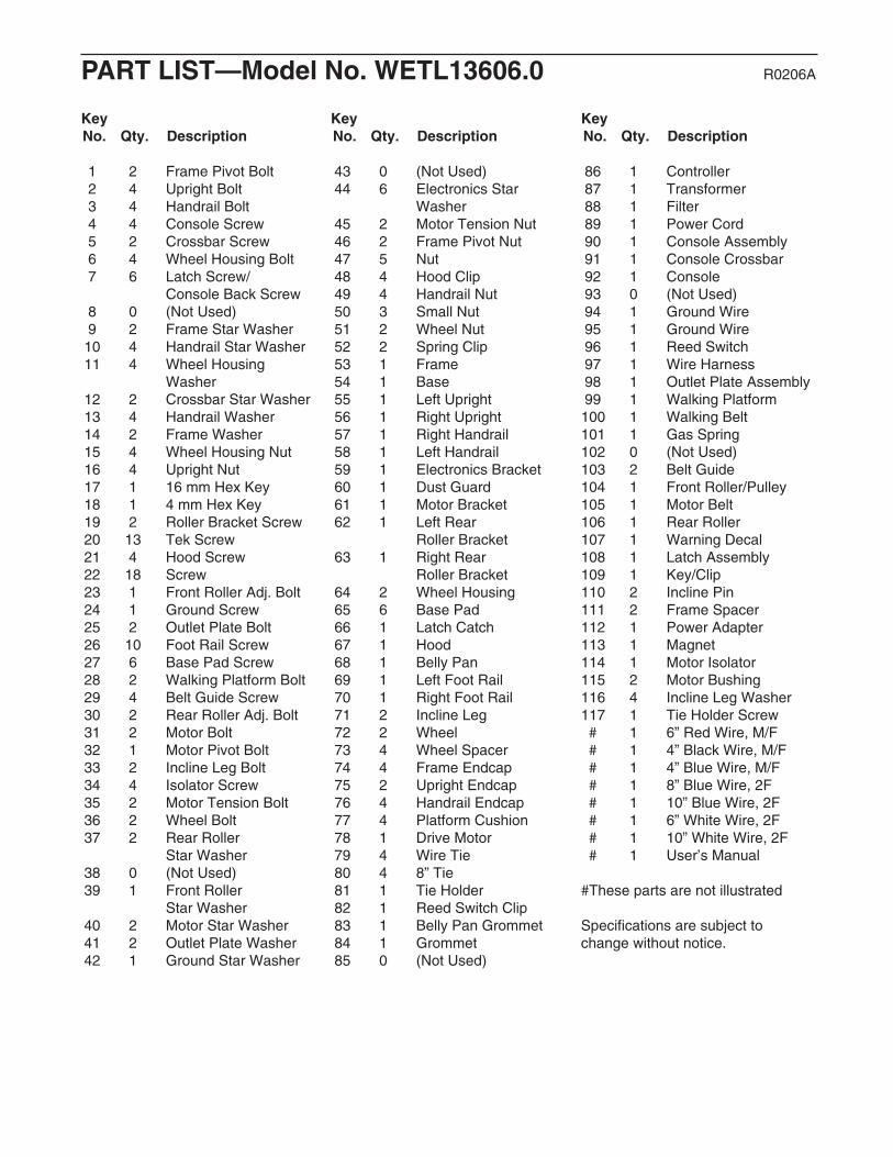
PART LIST—Model No. WETL13606.0 R0206A
Key No. Qty. Description
Key No. Qty. Description
Key No. Qty. Description
1 2 Frame Pivot Bolt2 4 Upright Bolt3 4 Handrail Bolt4 4 Console Screw5 2 Crossbar Screw6 4 Wheel Housing Bolt7 6 Latch Screw/
Console Back Screw8 0 (Not Used)9 2 Frame Star Washer10 4 Handrail Star Washer11 4 Wheel Housing
Washer12 2 Crossbar Star Washer13 4 Handrail Washer14 2 Frame Washer15 4 Wheel Housing Nut16 4 Upright Nut17 1 16 mm Hex Key 18 1 4 mm Hex Key 19 2 Roller Bracket Screw20 13 Tek Screw21 4 Hood Screw22 18 Screw23 1 Front Roller Adj. Bolt24 1 Ground Screw25 2 Outlet Plate Bolt26 10 Foot Rail Screw27 6 Base Pad Screw28 2 Walking Platform Bolt29 4 Belt Guide Screw30 2 Rear Roller Adj. Bolt31 2 Motor Bolt32 1 Motor Pivot Bolt33 2 Incline Leg Bolt34 4 Isolator Screw35 2 Motor Tension Bolt36 2 Wheel Bolt37 2 Rear Roller
Star Washer38 0 (Not Used)39 1 Front Roller
Star Washer40 2 Motor Star Washer41 2 Outlet Plate Washer42 1 Ground Star Washer
43 0 (Not Used)44 6 Electronics Star
Washer45 2 Motor Tension Nut46 2 Frame Pivot Nut47 5 Nut48 4 Hood Clip49 4 Handrail Nut50 3 Small Nut51 2 Wheel Nut52 2 Spring Clip53 1 Frame54 1 Base55 1 Left Upright56 1 Right Upright57 1 Right Handrail58 1 Left Handrail59 1 Electronics Bracket60 1 Dust Guard61 1 Motor Bracket62 1 Left Rear
Roller Bracket63 1 Right Rear
Roller Bracket64 2 Wheel Housing65 6 Base Pad66 1 Latch Catch67 1 Hood68 1 Belly Pan69 1 Left Foot Rail70 1 Right Foot Rail71 2 Incline Leg72 2 Wheel73 4 Wheel Spacer74 4 Frame Endcap75 2 Upright Endcap76 4 Handrail Endcap77 4 Platform Cushion78 1 Drive Motor79 4 Wire Tie80 4 8” Tie81 1 Tie Holder82 1 Reed Switch Clip83 1 Belly Pan Grommet84 1 Grommet85 0 (Not Used)
86 1 Controller87 1 Transformer88 1 Filter89 1 Power Cord90 1 Console Assembly91 1 Console Crossbar92 1 Console93 0 (Not Used)94 1 Ground Wire95 1 Ground Wire96 1 Reed Switch97 1 Wire Harness98 1 Outlet Plate Assembly99 1 Walking Platform100 1 Walking Belt101 1 Gas Spring102 0 (Not Used)103 2 Belt Guide104 1 Front Roller/Pulley105 1 Motor Belt106 1 Rear Roller107 1 Warning Decal108 1 Latch Assembly109 1 Key/Clip110 2 Incline Pin111 2 Frame Spacer112 1 Power Adapter113 1 Magnet114 1 Motor Isolator115 2 Motor Bushing116 4 Incline Leg Washer117 1 Tie Holder Screw# 1 6” Red Wire, M/F# 1 4” Black Wire, M/F# 1 4” Blue Wire, M/F# 1 8” Blue Wire, 2F# 1 10” Blue Wire, 2F# 1 6” White Wire, 2F# 1 10” White Wire, 2F# 1 User’s Manual
#These parts are not illustrated
Specifications are subject tochange without notice.

Frame Pivot Bolt (1)–2
Upright Bolt (2)–4
Handrail Bolt (3)–4
ConsoleScrew (4)–4
Wheel Housing Bolt (6)–4
CrossbarScrew (5)–2
Latch/ConsoleBack Screw
(7)–6
Frame StarWasher (9)–2
Handrail StarWasher (10)–4
Wheel HousingWasher (11)–4
Crossbar StarWasher (12)–2
HandrailWasher (13)–4
Frame Washer(14)–2
Wheel HousingNut (15)–4
Upright Nut(16)–4
Remove this chart and use it to identify small parts during assembly. Save this chart and the EXPLODEDDRAWING/PART LIST for future reference.
PART IDENTIFICATION CHART

7922
22
103
17
80
99
53
28
100
69
29
113
9622
82
103
109
56
54
36
7236
51
67
107
111
55
141
9
46
46
30
97
1
111
14
9
65
27
75
3
92
3540
45
32
78
47
65
27
65
2727
65
26
22
22
26
26
26
26
30
26
26
105
7108
35
26
77
77
20
31
74
74
66
20
61
40
104
70
63
62
3923
29
18
47
19
106
37
37
71 110
3347116
11671110
47
33116116
44
19
44
68
89
83
25
21
20
20
21
21
2260
41
41
50
21
77
20
34
77
28
59
86
87
22
88
73
73
5172
73
73
65
27
97
75
98
112
52
101
7
7
7
776
58
76
5776
76
20
20
20
91
4934
345
6
10
10
10
10
3
3
11
6
12
13
13
13
13
15
22
22
22
22
22
95
24
2765
42 44
44
44
47
48
48
48
48
50
64
64
84
90
94
115
114
81
22
20
20
512
25
49
4
34
34
117
81
11
15 16
162
2
34
34
1115 15
11
EXPLODED DRAWING—Model No. WETL13606.0 R0206A

Part No. 234233 R0206A Printed in China © 2006 ICON IP, Inc.
ORDERING REPLACEMENT PARTS
To order replacement parts, contact the ICON Health & Fitness, Ltd. office, or write:
ICON Health & Fitness, Ltd.Customer Service DepartmentUnit 4, Revie Road Industrial EstateRevie RoadBeestonLeeds, LS118JGUK
Tel:
Outside the UK: (44) 0113 387 7133Fax: (44) 0113 387 7125
To help us assist you, please be prepared to give the following information:
• the MODEL NUMBER of the product (WETL13606.0)
• the NAME of the product (WESLO CADENCE 55 treadmill)
• the SERIAL NUMBER of the product (see the front cover of this manual)
• the KEY NUMBER and DESCRIPTION of the desired part(s) (see the PART LIST and the EXPLODEDDRAWING in the centre of this manual)
08457 089 009