question paper (a-level) : paper 3 section a - june 2018
TRANSCRIPT

*JUN1874083A01* IB/M/Jun18/E9 7408/3A
For Examiner’s Use
Question Mark
1
2
3
TOTAL
Thursday 14 June 2018 Morning Materials For this paper you must have: • a pencil and a ruler • a scientific calculator • a Data and Formulae Booklet.
Instructions • Use black ink or black ball-point pen. • Fill in the boxes at the top of this page. • Answer all questions. • You must answer the questions in the spaces provided. Do not write
outside the box around each page or on blank pages. • Do all rough work in this book. Cross through any work you do not want
to be marked. • Show all your working.
Information • The marks for questions are shown in brackets. • The maximum mark for this paper is 45. • You are expected to use a scientific calculator where appropriate. • A Data and Formulae Booklet is provided as a loose insert.
Please write clearly in block capitals.
Centre number
Candidate number
Surname
Forename(s)
Candidate signature
A-level PHYSICS Paper 3 Section A
Time allowed: The total time for both sections of this paper is 2 hours. You are advised to spend approximately 70 minutes on this section.

2
*02* IB/M/Jun18/7408/3A
Do not write outside the
box Section A
Answer all questions in this section.
0 1
This question is about using a digital balance to investigate the force on a wire placed in a magnetic field when there is an electric current in the wire. A student carries out the procedure shown in Figure 1 and Figure 2. A metre ruler is pivoted at the 1.0 cm mark and a prism is placed on a digital balance. The free end of the ruler is raised and the balance is turned on and then set to zero, as shown in Figure 1.
Figure 1
The ruler is then supported by the prism with the apex of the prism at the 30.0 cm mark as shown in Figure 2. The height of the pivot is adjusted so that the ruler is horizontal.
Figure 2

3
*03*
Turn over ►
IB/M/Jun18/7408/3A
Do not write outside the
box
0 1
. 1
Deduce the mass of the ruler. State one assumption you make.
[3 marks]
mass of ruler =
g
assumption
Question 1 continues on the next page

4
*04* IB/M/Jun18/7408/3A
Do not write outside the
box
0 1
. 2
The student attaches a uniform wire to the upper edge of the ruler, as shown in Figure 3. The ends of the wire are connected to terminal blocks P and Q which are fixed firmly to the bench. A power supply and an ammeter are connected between P and Q. These modifications cause the balance reading to increase slightly.
A horizontal uniform magnetic field is applied, perpendicular to the wire, between the 85 cm and 90 cm marks, as shown in the close-up diagram in Figure 3.
Figure 3
The balance reading M is recorded for increasing values of current I. A graph of these data is shown in Figure 4.

5
*05*
Turn over ►
IB/M/Jun18/7408/3A
Do not write outside the
box
Figure 4
State and explain the direction of the horizontal uniform magnetic field.
[3 marks]
Question 1 continues on the next page

6
*06* IB/M/Jun18/7408/3A
Do not write outside the
box
0 1
. 3
It can be shown that B, the magnitude of the magnetic flux density of the horizontal uniform magnetic field, is given by
3B
L=
where = change in force acting on the prism per unit current in the wire
L = length of the region where the magnetic field cuts through the wire.
Determine B. [3 marks]
B = T

7
*07*
Turn over ►
IB/M/Jun18/7408/3A
Do not write outside the
box
0 1
. 4
The experiment is repeated with the ruler pivoted at the 99.0 cm mark. Nothing else is changed from Figure 3. This arrangement is shown in Figure 5.
Figure 5
Tick () one box in row 1 and one box in row 2 of Table 1 to identify the effect, if any,
on the magnitude of the forces acting on the apparatus as a certain current is passed through the wire.
Tick () one box in row 3 and one box in row 4 of Table 1 to identify the effect, if any, on the graph produced for this modified experiment compared with the graph in Figure 4.
[3 marks]
Table 1
Reduced No effect Increased
1 Force acting on the current-carrying wire due to the horizontal uniform magnetic field
2 Force acting on the prism due to the pivoted ruler
3 Gradient of the graph
4 Vertical intercept of the graph
Question 1 continues on the next page

8
*08* IB/M/Jun18/7408/3A
Do not write outside the
box
0 1
. 5
Figure 6 shows the balance being used to measure the forces between two wires. The connections joining these wires to the power supply are not shown. The pan of the balance moves a negligible amount during use and it supports a straight conducting wire X of horizontal length L. Terminal blocks are used to connect X into the circuit. The weight of these does not affect the balance reading. A second conducting wire Y is firmly supported a distance d above X.
Show, by adding detail to Figure 6, the wire connections that complete the circuit. The currents in X and Y must have the same magnitude and be in the directions indicated.
[2 marks]
Figure 6
9
*09*
Turn over ►
IB/M/Jun18/7408/3A
Do not write outside the
box
0 1
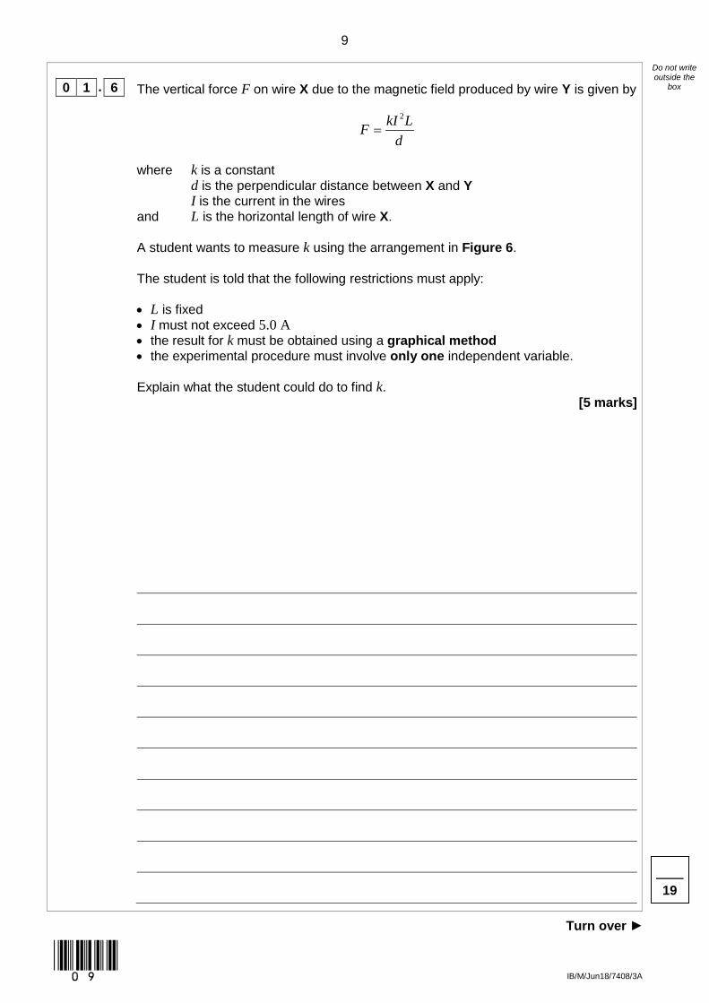
. 6
The vertical force F on wire X due to the magnetic field produced by wire Y is given by
2kI LFd
=
where
and
k is a constant d is the perpendicular distance between X and Y I is the current in the wires L is the horizontal length of wire X.
A student wants to measure k using the arrangement in Figure 6.
The student is told that the following restrictions must apply: • L is fixed • I must not exceed 5.0 A • the result for k must be obtained using a graphical method • the experimental procedure must involve only one independent variable. Explain what the student could do to find k.
[5 marks]
19

10
*10* IB/M/Jun18/7408/3A
Do not write outside the
box
0 2
This question is about an experiment with a retractable steel tape measure. The tape measure is placed at the edge of the bench and about 1 m of the steel tape is extended so that it overhangs the bench. The tape is then locked in this position to stop it from retracting. A student measures the dimensions x and y, the horizontal and vertical displacements of the free end of the tape, as shown in Figure 7.
Figure 7

11
*11*
Turn over ►
IB/M/Jun18/7408/3A
Do not write outside the
box
0 2
. 1
Describe a suitable procedure the student could use to measure y. You may add detail to Figure 7 to illustrate your answer.
[2 marks]
0 2
. 2
By changing the extension of the tape, the student obtains further values of x and y. These data are shown in Table 2.
Table 2
x / cm y / cm
132.4 61.2
116.8 33.7
105.1 24.3
94.5 15.6
84.3 11.0
73.2 5.7
Suggest why the student chose to make all measurements of x greater than 70 cm
[1 mark]
Question 2 continues on the next page

12
*12* IB/M/Jun18/7408/3A
Do not write outside the
box
0 2
. 3
The data from the experiment suggest that y = Axn where n is an integer and A is a constant.
These data are used to plot the graph in Figure 8.
Determine n using Figure 8.
[3 marks]
n =

13
*13*
Turn over ►
IB/M/Jun18/7408/3A
Do not write outside the
box
Figure 8
Question 2 continues on the next page

14
*14* IB/M/Jun18/7408/3A
Do not write outside the
box
0 2
. 4
Explain how the numerical value of A can be obtained from Figure 8. [3 marks]
0 2
. 5
Estimate the order of magnitude of A. You should use data for x and y from any one row in Table 2 on page 11. Give your answer with an appropriate unit.
[3 marks]
order of magnitude of A =
unit
12

15
*15*
Turn over ►
IB/M/Jun18/7408/3A
Do not write outside the
box
0 3
This question is about an experiment to estimate absolute zero. Figures 9a to 9d show the stages in the procedure carried out by a student.
An empty flask fitted with a tube and an open valve is placed in water bath H containing hot water. The air inside the flask is allowed to come into thermal equilibrium with the water. The valve is then closed, trapping a certain volume of air, as shown in Figure 9a.
Figure 9a
The flask is inverted and placed in water bath C in which the water is at room temperature. The air inside the flask is again allowed to come into thermal equilibrium with the water, as shown in Figure 9b.
Figure 9b
Question 3 continues on the next page

16
*16* IB/M/Jun18/7408/3A
Do not write outside the
box
The valve is opened and some water enters the flask, as shown in Figure 9c.
Figure 9c
The depth of the inverted flask is adjusted until the level of water inside the flask is the
same as the level in the water bath. The valve is then closed, trapping the air and the water inside the flask, as shown in Figure 9d.
Figure 9d
0 3
. 1
Explain why the volume of the air in the flask in Figure 9c is less than the volume of the air in the flask in Figure 9d.
[2 marks]

17
*17*
Turn over ►
IB/M/Jun18/7408/3A
Do not write outside the
box
0 3
. 2
Explain why Charles’s Law can be applied to compare the air in the flask in Figure 9a with the air in the flask in Figure 9d.
[2 marks]
0 3
. 3
The flask is removed from water bath C and the valve and stopper are removed. The volume of the water in the flask is V1 The flask is then completely refilled with water and the valve and stopper replaced. The volume of the water now in the flask is V2 The volumes V1 and V2 are shown by the shaded parts in Figure 10.
Figure 10
Explain how V1 and V2 can be determined.
In your answer you should • identify a suitable measuring instrument • explain a suitable procedure to eliminate possible systematic error.
[3 marks]
Question 3 continues on the next page

18
*18* IB/M/Jun18/7408/3A
Do not write outside the
box
0 3
. 4
Plot on Figure 11 points to show the volume V and the temperature θ of the air in the flask when • the flask is as shown in Figure 9a • the flask is as shown in Figure 9d.
The temperature of the hot water bath is 86 °C Room temperature is 19 °C V1 = 48 cm3 V2 = 255 cm3
[3 marks]
Figure 11

19
*19*
Turn over ►
IB/M/Jun18/7408/3A
Do not write outside the
box
0 3
. 5
Add a best fit line to your graph in Figure 11 to show how V should vary with θ according to Charles’s Law.
[1 mark]
0 3
. 6
Determine the value of absolute zero in °C using your graph in Figure 11. [3 marks]
value of absolute zero = °C
END OF QUESTIONS
14

20
*20* IB/M/Jun18/7408/3A
Do not write outside the
box
There are no questions printed on this page
DO NOT WRITE ON THIS PAGE ANSWER IN THE SPACES PROVIDED
Copyright information For confidentiality purposes, from the November 2015 examination series, acknowledgements of third party copyright material will be published in a separate booklet rather than including them on the examination paper or support materials. This booklet is published after each examination series and is available for free download from www.aqa.org.uk after the live examination series. Permission to reproduce all copyright material has been applied for. In some cases, efforts to contact copyright-holders may have been unsuccessful and AQA will be happy to rectify any omissions of acknowledgements. If you have any queries please contact the Copyright Team, AQA, Stag Hill House, Guildford, GU2 7XJ. Copyright © 2018 AQA and its licensors. All rights reserved.