quartz - aqva · email:[email protected] partno:293601...
TRANSCRIPT

Wireless remote installation instuctions page 1
The Waste Electrical and Electronic Equipment (Producer Responsibility) Regulation 2004
This product is outside the scope of the European Waste Electrical and Electronic Equipment Directive as interpreted within the UK.
In the UK this product can therefore be disposed of through commercial non-WEEE waste facilities.
The original manufacturer does not accept any liability under the WEEE directive.
Quartz®
Digitalremote control for Quartz and Axis

Wireless remote installation instuctions page 2
The Digital wireless remote is wireless and battery-less and provides a secondary method of the start/stop control to
Quartz Digital and Axis Digital shower systems. The Digital wireless remote can be sited up to 10m from the Digital
processor and fixed to any finished wall surface including glass and tiles.
THE DIGITAL WIRELESS REMOTE MUST BE SITED OUTSIDE THE SHOWERING AREA.
ALL SHOWERS REQUIRING AN ELECTRICAL CONNECTION MUST BE INSTALLED BY A QUALIFIED PERSON
FOLLOWING THE LATEST REVISION OF BS 7671 (WIRING REGULATIONS) AND CERTIFIED TO CURRENT
BUILDING REGULATIONS.
The Digital wireless remote is suitable for domestic use only.
Important information
Wireless remote installation instuctions page 3
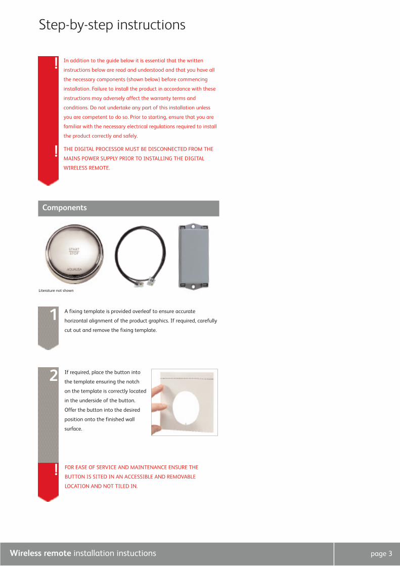
Step-by-step instructions
Literature not shown
In addition to the guide below it is essential that the written
instructions below are read and understood and that you have all
the necessary components (shown below) before commencing
installation. Failure to install the product in accordance with these
instructions may adversely affect the warranty terms and
conditions. Do not undertake any part of this installation unless
you are competent to do so. Prior to starting, ensure that you are
familiar with the necessary electrical regulations required to install
the product correctly and safely.
THE DIGITAL PROCESSOR MUST BE DISCONNECTED FROM THE
MAINS POWER SUPPLY PRIOR TO INSTALLING THE DIGITAL
WIRELESS REMOTE.
Components
A fixing template is provided overleaf to ensure accurate
horizontal alignment of the product graphics. If required, carefully
cut out and remove the fixing template.
1
!
!
If required, place the button into
the template ensuring the notch
on the template is correctly located
in the underside of the button.
Offer the button into the desired
position onto the finished wall
surface.
2
! FOR EASE OF SERVICE AND MAINTENANCE ENSURE THE
BUTTON IS SITED IN AN ACCESSIBLE AND REMOVABLE
LOCATION AND NOT TILED IN.

Wireless remote installation instuctions page 4
Use a spirit level placed onto the template to ensure horizontal
alignment of the graphics. Remove the paper backing from the
adhesive pad at the rear of the button and firmly fix the button
into position onto the finished wall surface.
3
! The button can be carefully removed and repositioned
IMMEDIATELY after first fixing if the graphics are misaligned
prior to the adhesive bond curing.
Loosen the securing screw on the
Digital processor box cable entry
flap and, if fitted, remove the
existing data cable using a flat
bladed screw driver to facilitate if
necessary.
4
Insert the Digital controller cable
plug (or connector block cable plug
from existing controller and hard
wired dual switch) into the receiver
box connector socket.
5
Connect one of the ends of the double ended short length of data
cable into the remaining socket in the receiver box.6
Secure the receiver box to a flat
horizontal surface using suitable
fixings.
7
! The top of the receiver box can be removed by first removing the
fixing screws securing the receiver box to the flat surface.
Disengage the two fixing lugs at one end of the box and carefully
lift the top clear.

Wireless remote installation instuctions page 5
Check all other connections are
sound and connect the remaining
end of the short length of low
voltage data cable to the Digital
processor via the socket located
just under the black protective flap.
Feed the cable out of the processor
by threading it under the small red
lip to the left of the socket, then
screw the flap back down to
provide a watertight seal.
8

Wireless remote installation instuctions page 6
After installation...
Commissioning1. Reconnect the power supply to the Digital processor.
2. Turn the Digital shower on using the Digital shower controller.
The LED light display should flash until the desired temperature has
been reached, when the LED light display will remain constant. Turn
the shower off using the Digital controller.
3. Turn the Digital shower on using the Digital wireless remote control.
When the shower has reached the desired temperature and the
flashing LED light display has remained constant, turn the shower off
using the wireless remote control.
4. Repeat the above process with all other possible combinations of
start/stop controls ensuring the Digital shower starts and stops
accordingly.
After installationRun through the Digital wireless remote control operation with the
purchaser and hand them this guide as well as the guide supplied with
the Digital shower unit.
Complete and post the Digital guarantee cards or register on-line at
www.aqualisa.co.uk
CleaningYour Quartz Digital shower system should be cleaned using only a soft
cloth and washing up liquid.
DO NOT USE ABRASIVE CLEANERS.

Aqualisa Products Limited
The Flyer’s Way
Westerham Kent TN16 1DE
Sales enquiries: 01959 560010
Republic of Ireland 01-864-3363
Customer helpline: 01959 560010
Republic of Ireland 01-844-3212
Brochure Hotline: 0800 652 3669
Website: www.aqualisa.co.uk
Email: [email protected] Part No:293601
Please note that calls may be recorded for training and quality purposes
The company reserves the right to alter, change or modify the product specifications without prior warning
® Registered Trademark Aqualisa Products Limited