quantumcalculationofthevavilov …vavilov-cherenkov radiation emitted by an electron in a...
TRANSCRIPT

arX
iv:1
602.
0509
9v1
[qu
ant-
ph]
16
Feb
2016
Quantum calculation of the Vavilov-Cherenkov radiation
by twisted electrons
I. P. Ivanov1, V. G. Serbo2,3, and V. A. Zaytsev4
1CFTP, Instituto Superior Tecnico, Universidade de Lisboa,
av. Rovisco Pais 1, 1049–001 Lisbon, Portugal2Novosibirsk State University, RUS–630090, Novosibirsk, Russia
3Sobolev Institute of Mathematics, RUS–630090, Novosibirsk, Russia4Department of Physics, St. Petersburg State University, Ulianovskaya 1,
Petrodvorets, 198504 St. Petersburg, Russia
September 3, 2018
Abstract
We present the detailed quantum electrodynamical description of Vavilov-Cherenkovradiation emitted by a relativistic twisted electron in the transparent medium. Simpleexpressions for the spectral and spectral-angular distributions as well as for the polar-ization properties of the emitted radiation are obtained. Unlike the plane-wave case, thetwisted electron produces radiation within the annular angular region, with enhancementtowards its boundaries. Additionally, the emitted photons can have linear polarizationnot only in the scattering plane but also in the orthogonal direction. We find that theVavilov-Cherenkov radiation emitted by an electron in a superposition of two vortexstates exhibits a strong azimuthal asymmetry. Thus, the Vavilov-Cherenkov radiationoffers itself as a convenient diagnostic tool of such electrons and complements the tradi-tional microscopic imaging.
1 Introduction
The Vavilov-Cherenkov (V-Ch) radiation was discovered in 1934 [1] and very soon explainedby Frank and Tamm [2] within classical electrodynamics. A few years later, Ginzburg gavethe quantum derivation of this phenomenon [3] and found quantum corrections to the classicalFrank-Tamm result. The quantum electrodynamic description is presented in Ref. [4]. Sincethat time, many facets of the Vavilov-Cherenkov radiation have been explored, see for examplethe old [5, 6] and the recent [7] reviews as well as monographs [8, 9].
Although the quantum theory of Vavilov-Cherenkov radiation was worked out more thanhalf a century ago, new theoretical publications on this topic still appear, see for example thevery recent papers [10, 11]. These works are in part driven by new experimental achievements
1

which make it possible to observe and investigate the V-Ch radiation under unusual circum-stances. The V-Ch radiation can then be accompanied by novel phenomena, and other effectswhich were previously considered uninteresting are brought to the forefront. It is clear thatthese opportunities require the appropriate theoretical description.
In this work, we develop the detailed quantum theory of the Vavilov-Cherenkov radiationemitted by vortex electrons. These are electron states whose wave function contains a topolog-ically protected phase vortex and which carry orbital angular momentum (OAM) with respectto their average propagation direction. Following the suggestion of Ref. [12], vortex electronbeams were experimentally demonstrated [13, 14] and a number of remarkable effects theyproduce was investigated [15]. Electromagnetic radiation of vortex electrons has not yet beeninvestigated experimentally, but theoretical works suggest that it should display interestingeffects in transition radiation [16, 17] and Vavilov-Cherenkov radiation [10].
We undertook this study despite there exists a very recent publication [10] on the sametopic, because we were not fully satisfied with its results and presentation. First, the formalismitself presented in the Supplementary materials of Ref. [10] is very far from optimal andobscures the physics. In the present paper, we develop a much more concise, convenient,and physically transparent formalism, based on the standard technology of helicity amplitudecalculation and on the exact description of vortex electrons. We accurately set up the notation,pinpoint all non-trivial technical details which arise in the course of calculation, and providethe physical insights for each interesting result.
Second, we perform a more complete study of the polarization properties, estimate thefeasibility of observing the spectral cut-off and the discontinuity, and the spin-flip contributionsmentioned in Ref. [10]. We also describe new effects produced by radiating vortex electrons,namely, the diagnostic power of the V-Ch radiation from vortex state superpositions, thespiraling pattern of the radiation of such electrons in the longitudinal magnetic fields, andthe peculiar phenomenon of V-Ch light concentration along the forward direction under anappropriate parameter choice.
Third, when studying Ref. [10], we found several erroneous or misleading statements andinterpretations of the results, and we will comment on them throughout our paper. Gettingthings right was also an important motivation for the present work.
The structure of the paper is as follows. In the next Section we remind the reader of thestandard quantum calculation of the V-Ch radiation by plane-wave electrons, and discuss therole of quantum corrections and the effect of non-plane-wave electrons. In Section 3 we repeatthis analysis for the Bessel vortex electron and describe in detail the novel effects which arisethere. Section 4 contains discussion of the results and comparison with previous works, andit is followed by conclusions. The two Appendices contain detailed calculations for the fullypolarized amplitude and for the case when all three particles are taken twisted.
2

2 Vavilov-Cherenkov radiation by a plane-wave electron
2.1 Kinematics
The V-Ch radiation can be treated within quantum electrodynamics (QED) as a decay process1
e(p) → e(p′) + γ(k), see e.g. Ref. [8], section 6. We use the following kinematical variables todescribe the initial and final plane-wave states:
p = (E,p), p′ = (E ′,p′), p2 = (p′)2 = m2e, v = |p|/E, (1)
k = (ω,k), |k| = ωn, k2 = −ω2(n2 − 1) < 0. (2)
In this work, we use the relativistic units ~ = 1, c = 1. The refraction index is frequency-
dependent, n = n(ω), but we assume that the resulting dispersion is small,∣
∣
∣
ωn
dndω
∣
∣
∣≪ 1.
We also assume that the medium is sufficiently transparent and homogeneous. The four-momentum conservation p = p′+k is guaranteed by the in-medium modification of the photondispersion relation. From this conservation law, we infer
k2 = −ω2(n2 − 1) = 2pk = 2Eω(1− vn cos θkp), (3)
where θkp is the angle of the emitted photon with respect to the initial electron direction,pk = |p| · |k| cos θkp. This angle is uniquely determined by the electron and photon energies:θkp = θ0, where
cos θ0 =1
vn+
ω
2E
n2 − 1
vn(4)
and is limited to 0 < θ0 < π/2.Now we remind the reader of how the QED calculation of this process proceeds. The
initial plane-wave electron with helicity λ (the spin projection onto the electron momentumdirection) is described with
Ψpλ(x) = Ne upλ e−ipx, (5)
where the bispinor upλ is normalized as upλ1upλ2
= 2me δλ1,λ2and N is the normalization
coefficient introduced below. The final electron is described with Ψp′λ′(x), and the emittedphoton is described by the plane wave
Aµ(x) = Nγ eµ e−ikx, kµeµ = 0, e∗µe
µ = −1. (6)
The coefficients
Ne =1√2EV
, Ne′ =1√2E ′V
, Nγ =1
n√2ωV
(7)
correspond to the normalization of one particle per large volume V. The scattering matrixelement for this decay is [20]
Spw = i√4πα
∫
Ψp′λ′(x)A∗(x)Ψpλ(x) d4x
= i(2π)4δ(p′ + k − p)Mfi NeNe′Nγ , Mfi =√4πα up′λ′ e∗upλ , (8)
1It is interesting to note that this problem is very close to the computation of the equivalent photon densitywithin the Weizsacker-Williams approximation to QED processes [18, 19].
3

where a hat over a four-vector corresponds to its contraction with γ-matrices: e.g. A = Aµγµ.
Squaring the S-matrix element (8), dividing it by the total time, and integrating it overthe final phase space gives the decay probability per unit time, that is, the decay widthΓpw = dWpw/dt. The normalization coefficients (7) together with the usual regularizationprescription for the square of the four-momentum δ-function guarantee that the final resultdoes not depend on the normalization volume. Integration over the final electron three-momentum removes three of the four delta-functions:
∫
δ(p′ + k − p) d3p′ = δ(E ′ + ω −E) =E ′
vEωnδ
(
cos θkp −1
vn− ω
2E
n2 − 1
vn
)
, (9)
and fixes the final electron energy E ′ =√
p2 + k2 − 2|p| |k| cos θ0 +m2e. The spectral-angular
distribution is thendΓpw
dω dΩ=
|Mfi|2
32π2vE2 δ (cos θkp − cos θ0) . (10)
This result corroborates the result (4) that, at given frequency ω, the photons are emitted,in the momentum space, along the surface of the cone with opening angle θ0. This angle,of course, slightly depends on ω, both due to dispersion and the proximity to the cut-offfrequency.
Choosing the z axis along the initial electron direction and performing the integration overthe photon polar angle θkp, we obtain
dΓpw
dω dϕk=
|Mfi|2
32π2vE2 , (11)
where ϕk is the azimuthal angle of the emitted photon.
2.2 The spectral-angular distribution
Evaluation of |Mfi|2 represents a basic QED calculation and can be easily performed evenwhen all particles are polarized. This fully-polarized case is considered in Appendix A. Here,we focus on the most relevant situation in which the initial electron is unpolarized and thefinal electron polarization is not detected. Then,
|Mfi|2 = 4πα1
2
∑
λλ′
|up′λ′ e∗ upλ|2 = 4πα Tr [(p+me)e(p′ +me)e
∗]
= 4πα (4 |pe|2 + k2 e∗e). (12)
In the Coulomb gauge, the photon polarization vector is purely spatial eµ = (0, e), e∗e = 1,and is orthogonal to the photon’s direction: ke = 0. Then, the spectral-angular distributiontakes the following form:
dΓpw
dω dϕk=
α
2π
[
|pe|2
vE2 +ω2
4vE2 (n2 − 1)
]
. (13)
This expression makes it clear that the emitted photon is linearly polarized in the scattering(p,k) plane. Let us define the polarization vector e‖ lying in this plane and e⊥ orthogonal to
4

it, and the degree of linear polarization according to
P pwl =
dΓ(‖)pw − dΓ(⊥)
pw
dΓ(‖)pw + dΓ(⊥)
pw
. (14)
Then, Pl > 0 indicates that the light is (partially) polarized in the scattering plane, whilePl < 0 corresponds to a partial polarization in the direction orthogonal to it. Evaluating theabove expression, we find
P pwl =
1
1 + d, d =
1
2
(
ω
vE sin θ0
)2
(n2 − 1). (15)
Under the standard conditions, the first term in Eq. (13) dominates; the quantity d is thenvery small, and the degree of linear polarization is close to 1.
It is not difficult to include the effects of the initial electron polarization, see Appendix A.It is known that, in the Weizsacker-Willams approach, the equivalent photon acquires circularpolarization proportional to the polarization of the initial electron [18, 19]. One should expectthe same effect for the Vavilov-Cherenkov radiation as well. The recent paper [11] claims that,in contradiction with this expectation, the emitted photons remain linearly polarized evenwith non-zero incoming electron polarization. This claim is incorrect, and in Appendix A weanalysis its origin.
Finally, if we do not detect the polarization of the final photon, we can sum decay proba-bility over its polarization states. The expression then becomes azimuthally symmetric, andone arrives at the spectral distribution:
dΓpw
dω= α
[
v sin2 θ0 +ω2
2vE2 (n2 − 1)
]
=α
vn2
[
v2n2 − 1− ω
E(n2 − 1) +
ω2
4E2 (n4 − 1)
]
. (16)
2.3 Quantum corrections and the spectral cut-off
Comparing the spectral distribution (16) with classical Frank-Tamm result dΓcl/dω = αv[1−(vn)−2], we see that
dΓpw
dω=
dΓcl
dω(1− η) , η =
ω
E
n2 − 1
v2n2 − 1− ω2
4E2
n4 − 1
v2n2 − 1, (17)
thus η quantifies the relative magnitude of the quantum corrections. Under the standardconditions, this factor is very small. Indeed, the sensitive medium used in the usual Cherenkovlight detectors has refraction index n ∼ 1, and they detect light which is emitted at sizablepolar angle, hence vn − 1 ∼ 1, which for optical photons gives η . 10−5. The relativemagnitude of the quantum corrections can be increased by adjusting the expression vn− 1 tobe very small, either for usual media or with a simultaneous increase of the refraction index n.However in both options we pay the price: the intensity of the V-Ch radiation gets stronglysuppressed. Just for illustration, we give below estimates for three typical sets of parameters.
Example 1, the standard case. We detect radiation with ω = 2.25 eV (green light) emittedwith moderately relativistic electron with v = 0.9 (kinetic energy 661 keV) in a medium with
5

refraction index n = 1.46. Then, vn − 1 = 0.31, the spectral density dΓpw/dω = 0.38α, andthe quantum correction η = 3 · 10−6, which can be safely neglected.
Example 2, with parameters borrowed from the recent paper [10]. The wavelength is thesame, the electron velocity is taken v = 0.685, which corresponds to the kinetic energy of 190keV, while the refraction index is highly tuned to be n = 1.45986. Under these conditions,the quantity vn− 1 drops by five order of magnitude, vn− 1 = 4.1 · 10−6. The importance ofquantum corrections increases up to η = 0.44, however the intensity dΓpw/dω = 3.1 · 10−6 α,which is again five order of magnitude smaller than in the standard case. Also, the V-Chradiation is emitted at the small angle of θ0 = 0.12. Detection of the V-Ch radiation underthese special conditions brings up many serious technical challenges.
Example 3. Here we consider the same green light with ω = 2.25 eV but emitted by a slowelectron with v = 0.0202 (kinetic energy is 104 eV) in a medium of very high refractive indexn = 50. This value is not inconceivable as it can be achieved, for example, in metamaterials,but it remains unclear whether the medium is sufficiently transparent to make V-Ch radiationdetectable. In any event, for this choice we obtain vn−1 = 0.01, and the quantum correctionsare also large, η = 0.55. The intensity in this case is less suppressed than in example 2 but isstill small, dΓpw/dω = 1.8 · 10−4 α.
Another quantum effect is the presence of the spectral cut-off:
ω < ωcutoff = 2Evn− 1
n2 − 1, (18)
which simply follows from Eq. (4) by the requirement θ0 > 0. Its existence was, of course,obvious since long ago, and it is usually considered irrelevant because, under the standardconditions, ωcutoff & 1 MeV. In fact, for such energetic photons, even the starting assumptionthat the radiation can be treated as an electromagnetic response of a continuous medium withsome refraction index is poorly justified.
However, it is conceivable that, by an appropriate medium choice, this cut-off frequencycan be brought into the visible region, as in examples 2 and 3. In this case, the usual approachto the V-Ch radiation is valid up to this cut-off. One then observes that the spectral densityis discontinuous at ω = ωcutoff . Indeed, just below the spectral cut-off, it takes the finite value
dΓcutoffpw
dω= α
ω2cutoff
2vE2 (n2 − 1) =2α
v
(vn− 1)2
n2 − 1. (19)
As ω → ωcuoff , the emission angle θ0 → 0, see Eq. (4), and both final particles move along thesame axis z. The angular momentum conservation then immediately leads to
λ = λ′ + λγ , (20)
where λ, λ′, and λγ are the helicities of the initial and final electron and of the emitted photon.This condition can only be satisfied by the helicity flip amplitudes, for which λγ = 2λ = −2λ′.This result also agrees with Eq. (15), which says that the degree of linear polarization P pw
l → 0as θ0 → 0. The explicit expressions for these amplitudes are given in Appendix A.
Unfortunately, observation of the cut-off step of the spectral distribution faces huge exper-imental challenges, not only because one needs to bring ωcutoff down to the visible range butalso because of the tiny intensity. For instance, within example 2, ωcutoff = 5.08 eV, which isin the near-UV range, and, from Eq. (19), we obtain dΓcutoff
pw /dω = 4.3 · 10−11 α, which agrees
6

with the value read from Fig. 3b in Ref. [10]. In example 3, we get ωcutoff = 4.1 eV anddΓcutoff
pw /dω = 10−6 α, which is much larger but still strongly suppressed with respect to thestandard case.
2.4 The role of the wave packets
We close this section with a discussion of an aspect which, although being rather clear, isusually not discussed and therefore can cause some confusion, which is illustrated by therecent paper [10]. Both the classical treatment and the above quantum treatment of theCherenkov radiation assume idealized non-physical descriptions of the electron. The formerapproach treats electron as a classical point-like source of fields, while the latter assumes theelectron to be a plane wave of infinite spatial extent. These two idealizations, despite beingopposite to each other, lead to the same results, up to the tiny ω/E corrections.
This aspect is, of course, generic and not specific to V-Ch radiation, and it is not surprisingthat the results of the two approaches agree with each other. In any real experiment, anelectron is a wave packet of certain transverse extent, which lies between the truly microscopicand macroscopic domains. It is true that the electron is not pointlike and it spreads as itpropagates. But under standard conditions, this spread is weak over experimental distanceseven if it moves in vacuum and is not subject to continuous interaction with the medium.Therefore, the electron usually does not spread to such an extent for which V-Ch radiationwould become very different from the point-like source result.
In a similar fashion, the wave packet is not a true plane wave but is a superposition of suchwaves. The V-Ch light emission from such an electron is an incoherent superposition of theradiation from individual plane-wave components (as we will see later for the vortex electron).Therefore, the wave packet nature amounts only to some smearing of the angular distributionof the V-Ch radiation.
In short, the fact that the electron is a wave packet provides, per se, a natural regularizationto certain otherwise ill-defined quantities, but it does not lead to dramatic modification of theV-Ch radiation properties. However, structuring this wave packet in a special way, one canstrongly modify its angular distribution, and this is where the vortex electrons lead to newinteresting results.
3 V-Ch radiation by a vortex electron
3.1 Kinematics
We now switch to the calculation of the V-Ch radiation from the vortex electron case. Wetake the initial electron in the form of cylindrical wave, known also as the Bessel vortex state,see details in Ref. [21]:
Ψκmpzλ(x) = Ntw
∫
d2p⊥
(2π)2aκm(p⊥) upλ e
−ipx, Ntw =
√
π
2ERLz, (21)
where the Fourier amplitude is
aκm(p⊥) = (−i)m eimϕp
√
2π
κδ(|p⊥| − κ) . (22)
7

Note that the normalization coefficient Ntw differs from Eq. (7) but it still corresponds to one(Bessel-state) particle per large cylindrical volume V = πR2Lz. In this state, the electronmoves, on average, along axis z with the longitudinal momentum pz > 0, while its trans-verse motion is represented by a superposition of plane waves with transverse momenta ofequal modulus κ and various azimuthal angles ϕp. This state also possesses a definite energyE =
√
κ2 + p2z +m2e, definite helicity λ, and a definite value of the total angular momentum
projection on the z axis: Jz = m, which is a half-integer.The final electron and photon states are described, as before, by plane waves. This is the
most appropriate choice for our physical problem, in which we integrate over the final electronstates and ask for photon’s angular distribution2.
In this case, the S-matrix is represented as a convolution of the plane-wave S-matrix (8)with the Fourier amplitude aκm(p⊥):
Stw = i(2π)4∫
d2p⊥
(2π)2δ(p′ + k − p) aκm(p⊥)Mfi(p, p
′, k)NtwNe′Nγ . (23)
Squaring it and using the regularization procedure for the square of the δ-function adapted tothe Bessel states [22, 23], we obtain
dΓtw = d3k
∫ 2π
0
dϕp
2π
|Mfi(p, p′, k)|2
32π2EE ′ωn2δ(E ′ + ω −E) . (24)
The expression (24) has one extra integration with respect to the plane-wave case, whichmodifies the angular distribution of the emitted radiation. This expression can be recast inthe following very revealing form
dΓtw
dω dΩ=
∫ 2π
0
dϕp
2π
dΓpw
dω dΩ. (25)
This form makes it obvious that the spectral-angular distribution for Bessel vortex state isgiven by an incoherent averaging over azimuthal angles of the plane-wave spectral-angulardistributions for incoming electrons with fixed polar angle θp = arctan(κ/pz).
Figs. 1 and 2 help to visualize the angular distribution of the V-Ch radiation from a Besselvortex electron. In Fig. 1 we show this construction on the stereographic projection map,which is equivalent to transverse plane for small polar angles, while in Fig. 2 we depict it in3D side view. The two images of Fig. 1 correspond to the two cases depending on which of theopening angles, the plane-wave V-Ch radiation angle θ0 and the conical angle of the Besselelectron θp, is the larger one. Every solid line circle corresponds to a single V-Ch ring emittedby a particular plane-wave component; the envelop of all such circles represent the angulardistribution for the Bessel electron.
Already this geometric construction makes it clear that in both cases, θ0 > θp and θ0 < θp,the radiation is emitted in the annual region with polar angles θk spanning from |θp − θ0| toθp + θ0. In particular, for sufficiently large θ0 and θp, one can have θp + θ0 > π/2, whichformally means that a part of this radiation is emitted backwards with respect to the average
2 Formally, one can also represent the final photon by vortex states and predict its OAM distribution.However experimental measurement of this distribution will hardly be possible with the modern technologyas it requires a coherent macroscopic detector able to project the outgoing wave onto cylindrical states withdifferent values of OAM.
8
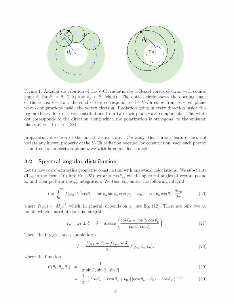
Figure 1: Angular distribution of the V-Ch radiation by a Bessel vortex electron with conicalangle θp for θp > θ0 (left) and θp < θ0 (right). The dotted circle shows the opening angleof the vortex electron; the solid circles correspond to the V-Ch cones from selected plane-wave configurations inside the vortex electron. Radiation going in every direction inside thisregion (black dot) receives contributions from two such plane-wave components. The whitedot corresponds to the direction along which the polarization is orthogonal to the emissionplane, K = −1 in Eq. (38).
propagation direction of the initial vortex state. Certainly, this curious feature does notviolate any known property of the V-Ch radiation because, by construction, each such photonis emitted by an electron plane-wave with large incidence angle.
3.2 Spectral-angular distribution
Let us now corroborate this geometric construction with analytical calculations. We substitutedΓpw in the form (10) into Eq. (25), express cos θkp via the spherical angles of vectors p andk, and then perform the ϕp integration. We then encounter the following integral
I =
∫ 2π
0
f(ϕp) δ [cos θ0 − sin θk sin θp cos(ϕp − ϕk)− cos θk cos θp]dϕp
2π. (26)
where f(ϕp) = |Mfi|2, which, in general, depends on ϕp, see Eq. (12). There are only two ϕp
points which contribute to this integral,
ϕp = ϕk ± δ, δ = arccos
(
cos θ0 − cos θk cos θpsin θk sin θp
)
. (27)
Then, the integral takes simple form
I =f(ϕk + δ) + f(ϕk − δ)
2F (θk, θp, θ0). (28)
where the function
F (θk, θp, θ0) =1
π sin θk sin θp| sin δ|(29)
=1
π[cos θk − cos(θp + θ0)] [cos(θp − θ0)− cos θk]−1/2 (30)
9

z
~p
θp
ϕp
~k
ϕk
θ0
θk
|θ0 − θp|θ0 + θp
Figure 2: The geometry of the V-Ch emission by a vortex electron in a 3D side view.
is symmetric under arbitrary permutations of its three arguments. It is non-zero only whenthey satisfy the “triangle inequality”
|θp − θ0| < θk < θp + θ0 . (31)
It diverges at the borders of this interval, however this singularity is integrable, as
∫ θp+θ0
|θp−θ0|
F (θk, θp, θ0) sin θk dθk = 1. (32)
This function has a minimum inside the annular region,
minF (θk, θp, θ0) =1
π sin θp sin θ0at θk = arccos (cos θp cos θ0). (33)
In Fig. 3, this function is plotted for various values of θp and for θ0 = 14.5, which correspondsto ω = 2.25 eV (green light), refraction index of n = 1.33 (water), and the electron kineticenergy of 300 keV (v = 0.78), which is typical for electron microscopes. The spectral-angulardistribution for the vortex electron V-Ch radiation can then be compactly written as
dΓtw
dω dΩ=
α
2πv
[
〈|pe|2〉E2 +
ω2
4E2 (n2 − 1)
]
F (θk, θp, θ0), (34)
where
〈|pe|2〉 = 1
2
(
|pe|2∣
∣
ϕp=ϕk+δ+ |pe|2
∣
∣
ϕp=ϕk−δ
)
. (35)
10

0
10
20
30
0 10 20 30 40
F(θ
k,θ
p,θ
0)
-1
-0.5
0
0.5
1
0 10 20 30 40
K
θk (deg)
θp = 6
θp = 12
θp = 18
Figure 3: The function F (θk, θp, θ0) defined in Eq. (29) (upper plot) and the quantity Kdefined in Eq. (37) (lower plot) as functions of the photon polar angle for θ0 = 14.5.
3.3 Polarization properties
The expression (34) is convenient for the two choices of the photon linear polarization vector3:e‖ lying in the scattering plane spanned by the z axis and the vector k, and e⊥ orthogonal toit. With this definitions, we can again calculate the degree of linear polarization
P twl =
dΓ(‖)tw − dΓ
(⊥)tw
dΓ(‖)tw + dΓ
(⊥)tw
=K
1 + d= K P pw
l , (36)
where the quantity
K = 2(cos θk cos θ0 − cos θp)
2
sin2 θk sin2 θ0− 1 (37)
describes how the degree of linear polarization for V-Ch photons emitted in a given direction ismodified when we switch from the plane wave to the vortex electron. This quantity is plotted
3Strictly speaking, the polarization state of a non-plane-wave photon is characterized by polarization fieldrather than polarization vector. With the full rigor, our definitions correspond to the so-called radial polar-ization, for the former choice, and the azimuthal polarization, for the latter choice. However when we discussangular distribution, we already select a direction of the photon and define a polarization vector at that point.
11

in the lower graph of Fig. 3. It always satisfies the condition −1 ≤ K ≤ 1. It attains itsmaximal value K = 1 at the borders of the interval (31), while its minimal value depends onthe relation between θ0 and θp:
for θp > θ0, minK = −1 at cos θk =cos θpcos θ0
, (38)
for θp < θ0, minK = 1− 2sin2 θp
sin2 θ0at cos θk =
cos θ0cos θp
. (39)
Notice that negative values of K correspond to the linear polarization which is orthogonal
Figure 4: The degree of linear polarization P twl for a range of angles θk and θp for the same
parameter choice as before.
to the scattering plane, a situation which is impossible for usual plane-wave scattering. Thispeculiar feature is, however, of purely kinematical origin and arises from the mismatch of thetrue scattering plane (that is, the plane formed by the direction of the photon and of theelectron plane-wave component emitting this photon) and the overall scattering plane (thedirection between the photon and the average direction of the vortex electron state). Thepoint corresponding to the value K = −1 is also shown in Fig. 1 with a white dot. Forcompleteness, we also show in Fig. 4 the degree of linear polarization as a function of thevortex electron opening angle and the polar angle of the emitted photon.
Alternatively, one can describe the emitted photon polarization in terms of definite helicitystates, λγ = ±1, which are described with vectors e(±) = ∓
(
e‖ ± ie⊥)
/√2. One then checks
that the spectral-angular distribution is independent of the helicity, dΓ(+)tw = dΓ
(−)tw , and is
azimuthally symmetric. From here, just by multiplying by 2, one immediately obtains thespectral-angular distribution summed over the final photon polarizations:
dΓtw
dω dΩ= 2
dΓ(±)tw
dω dΩ=
α
2π
[
v sin2 θ0 +ω2
2vE2 (n2 − 1)
]
F (θk, θp, θ0). (40)
12

The spectral distribution can be obtained after angular integral with the aid of Eq. (32).There exists however a more direct way. We notice that after summation over photon polar-izations, dΓpw does not depend on the p direction. Therefore, the ϕp integration of Eq. (25)is immediately performed, and we obtain
dΓtw
dω=
dΓpw
dω= α
[
v sin2 θ0 +ω2
2vE2 (n2 − 1)
]
. (41)
In short, the spectral distribution of the V-Ch radiation by the twisted electron is identical tothe plane-wave case.
3.4 Vavilov-Cherenkov radiation by a superposition of two vortexstates
Let us consider now the case when the incoming electron is not a Jz eigenstate but is asuperposition of two such states with different values m1 and m2 but with the same κ andpz, and, therefore, with the same energy E =
√
κ2 + p2z +m2e. This state corresponds to a
modification of Eq. (21) in which aκm(p⊥) is replaced by
c1aκm1(p⊥) + c2aκm2
(p⊥), ci = |ci|eiαi , |c1|2 + |c2|2 = 1 . (42)
This leads to an additional factor under the ϕp integral in Eqs. (25) and (26):
G(ϕp) = 1 + 2 |c1c2| cos[∆m(ϕp − π/2) + ∆α] , (43)
where ∆m = m2 −m1, ∆α = α2 − α1.For simplicity, we limit ourselves to the case when the photon polarization is not detected;
if needed, the polarization dependence can be studied in the same manner as before. Then,expression (28) contains an additional factor
2πΦ(ϕk) =1
2[G(ϕk + δ) +G(ϕk − δ)] = 1 + A cos[∆m(ϕk − π/2) + ∆α], (44)
A = 2 |c1c2| cos(δ ·∆m) . (45)
The spectral-angular distribution (40) then takes the following form:
dΓtw
dω dΩ= α
[
v sin2 θ0 +ω2
2vE2 (n2 − 1)
]
F (θk, θp, θ0) Φ(ϕk). (46)
Thus, we observe the appearance of azimuthal asymmetry in the V-Ch radiation of suchelectrons. This asymmetry depends on ∆m = m2 − m1 as well as on the phase difference∆α = α2−α1, and its magnitude is quantified by A in Eq. (45), which, by definition, satisfies|A| ≤ 1.
The spectral-angular distribution over the spherical angles of the emitted photons (θk, ϕk)is shown in Fig. 5 for θp = θ0/2, ∆m = ±3, ∆α = π/2, |c1| = |c2| = 1/
√2 and in Fig. 6 for
∆m = 3, ∆α = 0, |c1| = |c2| = 1/√2.
Finally, as expected, the dependence on ∆m and ∆α disappears after the integration overthe photon directions,
∫
F (θk, θp, θ0) Φ(ϕk) dΩ = 1 , (47)
and we are back to the spectral distribution (41).
13

Figure 5: The spectral-angular distribution as a function of emitted photon spherical angles θkand ϕk for θp = θ0/2 and for the superposition with ∆m = ±3, ∆α = π/2, |c1| = |c2| = 1/
√2.
Figure 6: The spectral-angular distribution as a function of emitted photon spherical anglesθk and ϕk for the superposition with ∆m = 3, ∆α = 0, |c1| = |c2| = 1/
√2. The size of the
circle is proportional to θk.
4 Discussion
4.1 Vavilov-Cherenkov radiation as a diagnostic tool
The results of the previous section make the V-Ch radiation a convenient macroscopic diag-nostic tool for electron vortex beams. By measuring the parameters of the annular region,one can determine the angles θp and θ0, and deduce from them the energy E and the conicalmomentum κ of the vortex electron.
This method is also very convenient for checking that the vortex electron is indeed in asuperposition of several OAM states. A conventional method for doing that is to place a screenin the focal plane of the electron microscope and detect the multi-petal image. This is a mi-croscopic observation method. Our calculations show that V-Ch radiation from such electronsoffer a complementary, macroscopic diagnostic tool which reveals the OAM-superposition state
14

even for tightly focused electrons.Moreover, this is a non-intercepting method since the electrons are allowed to pass through.
As a result, it offers itself as a convenient method to measure the OAM-induced Larmor andGouy rotations of the vortex electrons propagating in the longitudinal magnetic field [24].The existing approach requires repeated measurements with fluorescent screens placed atdifferent distances downstream the beam. Here, the same effect can be detected in a singlemacroscopic experiment. As the multi-petal electron beam propagates and rotates, its V-Ch radiation will show the correspondingly rotating multi-petal image. A single large-areapixelized photodetector placed at the back end of the medium will show a spiraling V-Chradiation pattern.
The proposed type of experiment can be also used beyond vortex state superpositions todetect, in a macroscopic fashion, other forms of tightly focused coherently structured electronbeams.
4.2 “Cherenkov concentrator”
By appropriately adjusting the parameters, one can reach the regime of θp = θ0. In this case,the annular region shown in Fig. 1 becomes the full disk, and the V-Ch radiation can beemitted arbitrarily close to the axis z of the average direction of the vortex electron. In thevicinity of this direction, that is, at small θk ≪ 1, the function F (θk, θp = θ0, θ0) is
F (θk, θp = θ0, θ0) =1
2π sin(θk/2)
1√
sin2 θ0 − sin2(θk/2)≈ 1
π sin θ0
1
θk. (48)
One observes a remarkable regime of V-Ch radiation being “concentrated” near the forwarddirection, see the middle plot in Fig. 6. If one selects a very small solid angle near the forwarddirection, θk ≤ ϑ, ∆Ω = πϑ2 ≪ 1, then a small but sizable part, O(ϑ), of the total emittedV-Ch light will be emitted in this very small solid angle. As a result, we obtain a brightsource of V-Ch radiation aligned with the direction of the vortex electron. The degree oflinear polarization of this light will be close to −1, that is, the polarization vector will bealigned in the azimutal direction.
This peculiar regime of the V-Ch radiation has never been observed before. Its experimen-tal observation is possible with today’s technology.
4.3 Comparison with the semiclassical approach
It is also interesting to compare our results with the semiclassical approach to the calculation ofV-Ch radiation from a vortex electron presented in Ref. [17] as a pedagogical example en route
to the more complicated transition radiation. In that work, the vortex electron was modeledby a point charge equipped with a magnetic moment µ. This emergent magnetic moment wastaken proportional to the total angular momentum m, as was derived in the original workon semiclassical dynamics of vortex electron wave packets [12]. With this simplistic model,Ref. [17] recovered the Tamm-Frank result for the spectral distribution of the V-Ch radiationfrom such a source, which, in our notation, can be written as
dΓtw;semicl.
dω=
dΓcl
dω
[
1 +(
mωn
2Ev
)2]
, (49)
15

and which describes the sum of the V-Ch radiation intensities from the electric and magneticcurrents.
Comparing this semiclassical expression with our results, we can make two observations.First, the extra term in Eq. (49) is suppressed by ω2/E2. For small m, it is smaller than thefirst quantum correction, see Eq. (17), and keeping it would go beyond the approximationsused in the semiclassical evaluation. However, for very large m, of the order of thousands(electron vortex beams with orbital angular momentum up to 100 was already observed inRefs. [14, 25]), this contribution can overcome the quantum correction and keeping it willbecome legitimate. The calculations of Ref. [17] assume this regime.
Second, expression (49) explicitly depends on the vortex electron angular momentum m,while our results for vortex electrons are m-independent. Even though the pure Bessel state,which we use, and the compact vortex wave packet used in Ref. [17] are different, the appear-ance of m-dependence is worrisome. We believe that this discrepancy signals the breakdown,for the V-Ch radiation problem, of the semiclassical model which views a vortex electron as apointlike object with unresolved structure.
4.4 Remarks on the recent publication by Kaminer et al. [10]
The V-Ch radiation by the vortex electrons was the subject of the recent publication [10].Both our work and that publication focus on calculating the spectral-angular distribution andthe polarization properties of the V-Ch light, and we agree on some results4. However westrongly object to several physics interpretations and claims made in [10]. Below, we list themone by one.
• The authors of Ref. [10] claim that the discontinuity of dΓω/dω at the cut-off frequencyω = ωcutoff (18) is a novel feature, which arises due to the wave-packet nature of thevortex electron and which represents “...a clear deviation from the conventional ChR
theory that displays no such cutoffs or discontinuities whatsoever.”
This claim is wrong. We show in Sect. 2.3 that the conventional plane-wave approachto the V-Ch radiation reproduces this spectral feature, see Eq. (19). We reiterate herethe point that the spectral distribution of the V-Ch radiation by vortex electron, and ingeneral by any monochromatic wave packet, must coincide with the plane-wave spectraldistribution. Also, the dominance of the spin-flip amplitudes at the cut-off frequency hasan absolutely clear origin, the helicity conservation in the strictly forward scattering, andis also a part of the standard V-Ch radiation treatment, see our discussion in Sect. 2.3.
• The authors of Ref. [10] attribute special significance to the fact that the initial vortexelectron is a coherent superposition of plane wave electron states. They claim that it isthis additional feature “... that gives rise to the new effects involving the OAM of the
electron and photon”.
This statement is misleading. As we showed above, when the final electron is integratedout and we consider the spectral-angular distribution, the initial coherence is lost becauseno two initial plane-wave components can lead to an identical final state. All novelfeature of the V-Ch radiation by vortex electrons, for example, the ring structure of
4Note that we compare our results with the last, published version of [10], and do not consider the drasticallydifferent earlier arXiv version.
16
the angular distribution, follow from incoherent superposition of radiation by individualplane wave components.
• Eq. (3) in Ref. [10] is incorrect and must be replaced by our Eq. (71) in Appendix B.Whether this change affects any of the results, including pictures, of Ref. [10] can onlybe answered by the authors of that publication.
• The authors of Ref. [10] conclude by saying that they have found quantum corrections tothe V-Ch radiation process which originate from their using of non-plane-wave electronsand stress that “... any scattering process should involve similar quantum corrections
that follow from the particle wave structure.”
This statement is misleading. As we show, there is no quantum correction to the spectral-angular distribution which could originate from the non-plane-wave nature of the elec-tron. All changes, such as the annular shape of the angular distribution, the possibility ofθk > π/2, and the unusual polarization properties, are classical and survive at ω/E → 0.
5 Conclusions
In this work, we gave the full quantum mechanical treatment of the V-Ch radiation emittedby a vortex electron and compared it with the standard plane-wave case. We investigated thespectral, angular, and polarization properties, and discussed the roles of quantum effects, ofthe coherence, and of the non-plane-wave nature of the vortex state. We also gave transparentphysical explanations to various effects the calculations lead to.
Taking the electron as a superposition of two vortex states, we found two remarkableeffects: the possibility of multi-petal spiraling structure of the V-Ch radiation emitted bysuch an electron in a longitudinal magnetic field, and a remarkable concentration of the V-Chlight in the forward direction when the opening angles of the electron vortex state and theV-Ch cone match. Both effects are new and can be observed with the existing technology.We also discussed the possibility of utilizing the V-Ch radiation as a diagnostic tool for thedetermination of the vortex electrons parameters and for testing the purity of the vortex state.
Our paper contains not only results and physics insights but also a detailed exposition ofthe formalism appropriate for calculation of V-Ch radiation from vortex electrons. We hopewe have presented and discussed enough technical details to enable the reader to repeat ourcalculations and to apply this machinery to other processes.
Finally, we critically commented on several claims made recently in literature on the spec-tral, angular, and polarization properties the V-Ch radiation, as well as on the role of coher-ence, quantum corrections, and deviations of the V-Ch radiation of non-plane-wave electronsfrom the plane-wave case.
We are grateful to G. Kotkin, V. Prinz, and V. Telnov for useful discussions. The work ofI.P.I. was supported by the Portuguese Fundacao para a Ciencia e a Tecnologia (FCT) throughthe FCT Investigator contract IF/00989/2014/CP1214/CT0004 under the IF2014 Programme,as well as under contracts UID/FIS/00777/2013 and CERN/FIS-NUC/0010/2015, which arepartially funded through POCTI (FEDER), COMPETE, QREN, and the EU. I.P.I. is alsothankful to Helmholtz Institut Jena for hospitality during his stay as a Visiting Professor
17

funded by the ExtreMe Matter Institute EMMI, GSI Helmholtzzentrum fur Schwerionen-forschung, Darmstadt. V.G.S. acknowledges support from RFBR via Grant No. 15-02-05868.The work of V.A.Z. was supported by RFBR (Grant No. 16-02-00334) and by SPbSU (GrantsNo. 11.38.269.2014 and No. 11.38.237.2015).
A Vavilov-Cherenkov radiation amplitude in a fully po-
larized set-up
Here, for completeness, we derive the amplitudeMfi (see Eq. (8)) for the case when all particlesare polarized. The initial and final electron helicities are denoted as λ and λ′, respectively,while the photons are also taken to be circularly polarized with helicity λγ. Note that weconsider the general kinematics, without aligning the initial electron along a predefined axisz.
The initial electron bispinor has the following form (see derivation in Ref. [21]):
upλ =∑
σ=±1/2
e−iσϕp d1/2σλ (θp)U
(σ)(E, λ), (50)
where dJMM ′ (θ) is the Wigner matrix [26, 27] and the basis bispinors U (σ)(E, λ) are expressedas follows,
U (σ)(E, λ) =
( √E +me w
(σ)
2λ√E −me w
(σ)
)
, w(+1/2) =
(
10
)
, w(−1/2) =
(
01
)
. (51)
They do not depend on the direction of p and are eigenstates of the spin projection operatorsz with eigenvalues σ = ±1/2. The final electron bispinor up′λ′ is constructed in a similarway. The polarization state of the photon is described in the same formalism (see details inRef. [28]):
ekλγ=
∑
σγ=0,±1
e−iσγϕk d 1σγλγ
(θk)χσγ, (52)
where the basis vectors
χ0 =
001
, χ±1 =∓1√2
1±i0
(53)
represent the eigenstates of the photon spin z-projection operator with the eigenvalues σγ =0, ±1.
The scattering amplitude (8) takes then the following form
Mfi = −√4πα up′λ′ e∗kλγ
upλ
= −√4πα
∑
σσ′σγ
ei(σ′ϕp′+σγϕk−λϕp) d
1/2σλ (θp)d
1/2σ′λ′(θp′)d
1σ−σ′, λγ
(θk)W(σσ′σγ), (54)
where
W (σσ′σγ) = U(σ′)
(E ′, λ′) (γχ∗σγ)U (σ)(E, λ)
=[
2λ√
(E −me)(E ′ +me) + 2λ′√
(E ′ −me)(E +me)]
×[
2σ(
δσ, σ′ −√2 δσ,−σ′
)]
δσγ , σ−σ′ . (55)
18

which shows that each individual non-zero term in Eq. (54) complies with the spin z-projectionconservation law:
σ = σ′ + σγ . (56)
The triple summation in Eq. (54) becomes effectively just a double summation over σ and σ′.We can now simplify this general kinematics by selecting the z axis along the direction
of the initial electron, θp = ϕp = 0. Then d1/2σ λ (θp) = δσ λ, ϕp′ = ϕk + π, and the scattering
amplitude becomes
Mfi = −√4πα
[
√
(E −me)(E ′ +me) + (2λ)(2λ′)√
(E ′ −me)(E +me)]
eiλϕk
×∑
σ′=±1/2
eiπσ′
d1/2σ′λ′(θp′)d
1λ−σ′, λγ
(θk)(
δλ, σ′ −√2 δλ,−σ′
)
, (57)
with the θk and θp′ related by ωn sin θk = |p′| sin θp′ .Here, we first remark that for the strictly forward scattering, which corresponds to the
ω = ωcutoff limit, d1/2σ′λ′(θp′) = δσ′, λ′ and d 1
λ−σ′, λγ(θk) = δλ−σ′, λγ
, and therefore only the helicityflip amplitude survives:
M forwardfi =
√8πα
[
√
(E −me)(E ′ +me)−√
(E ′ −me)(E +me)]
eiλ(ϕk−π)δλ′,−λδλγ , 2λ. (58)
This result is a straightforward consequence of the helicity conservation law, which is alwaysexpected at the cut-off frequency, and has nothing to do with the choice of the electron wavefunction. Thus, the spectral distribution approaches the finite value in this limit:
dΓforwardpw
dω=
∣
∣M forwardfi
∣
∣
2
16πvE2 =α
2v
(ω
E
)2 [vE − n(E +me)]2
(E +me)(E′ +me)
, (59)
and its value is suppressed by the small parameter (ω/E)2.The helicity amplitudes derived above give a convenient basis to calculate this process for
arbitrarily polarized particles. Let us assume that the initial electron has arbitrary polarizationdescribed by the 4-vector
aµ = (a0, a), a0 =pζ
me
, a = ζ +(pζ)
me(E +me)p (60)
where ζ is twice the average value of the electron spin in its rest frame. In this case, the result(12) must be supplemented with an extra term
∆ |Mfi|2 = −8παime εµναβe∗µeνkαaβ . (61)
Clearly, this expression is zero when e∗µ = eµ, which corresponds to the linear polarization of
the photon. For circularly polarized photons with(
e(λγ )µ
)∗
= −e(−λγ )µ , we get
∆ |Mfi|2 = 8παλγmeω
(
a0n− ak
ωn
)
, (62)
where λγ = ±1. The recent work [11] assumes, without any justification, that e∗µ = eµ,which leads to the erroneous conclusion that the V-Ch radiation does not acquire circularpolarization even if the initial electron is polarized.
19
In fact, it does. To see this, we present the electron polarization vector as
ζ = ζ‖ + ζ⊥, ζ‖ = p(ζp)
p2 = 2〈λ〉 p
|p| , (63)
where 〈λ〉 is the average helicity of the initial electron. Then,
∆ |Mfi|2 = 8παλγωE
[
2〈λ〉(vn− cos θ0)−me
E
ζ⊥k
nω
]
. (64)
The degree of the circular polarization of the V-Ch photon is then
P pwc =
dΓ(λγ=+1)pw − dΓ(λγ=−1)
pw
dΓ(λγ=+1)pw + dΓ(λγ=−1)
pw
=ω
Ev2 sin2 θ0
2〈λ〉(vn− cos θ0)−me
E
ζ⊥k
nω1 + d
, (65)
and it is non-zero when the initial electron has a non-zero polarization ζ 6= 0. Under normalconditions, this polarization is small. However at the spectral cut-off and with 〈λ〉 = +1/2,we get P pw
c = +1, in accordance with Eq. (58).
B Vavilov-Cherenkov radiation amplitude in the all-vortex
basis
All the above derivations were done for the V-Ch radiation from plane-wave electrons andfor arbitrary polarization of all particles. Here, we present the construction of the S-matrixelement for the arbitrary polarized vortex states, including also the case when all three particlesare twisted. Although this approach is not the most convenient one for calculation of spectral-angular distribution, we give the results for sake of completeness. We stress that they canbe obtained by direct combination of the formalisms and compilation of the results which arealready known and published in Refs. [21, 23, 28].
Once again, the initial vortex electron is described by the Bessel state (21). In the cylin-drical coordinates ρ, ϕ, z, it takes the following form (see details in Ref. [21]):
Ψκmpzλ(ρ, ϕ, z, t) = Ntw e−iEt+ipzz
√
κ
2π
∑
σ=±1/2
(−i)σ ei(m−σ)ϕ d1/2σλ (θp)
× Jm−σ(κρ)U(σ)(E, λ), (66)
with the bispinor U (σ)(E, λ) defined in Eq. (51). The similar function Ψκ′m′p′zλ′(ρ, ϕ, z, t)
describes the final electron. The Bessel vortex photon moving along axis z with momentum kz,and having a definite modulus of the transverse momentum κγ , definite energy ω =
√
κ2γ + k2
z ,as well as definite helicity λγ and the z-projection of the total spin Jz = mγ , is described byAµ(x) = (0, A(x)) (see details in Ref. [28]):
Aκγmγkzλγ(ρ, ϕ, z, t) = Nγ
tw
∫
d2k⊥
(2π)2aκγmγ
(k⊥) eµkλγ
e−ikx
= Nγtw e−iωt+ikzz
√
κγ
2π
∑
σγ=0,±1
(−i)σγ ei(mγ−σγ)ϕ d 1σγλγ
(θk)
×Jmγ−σγ(κγρ)χσγ
, (67)
20

where the normalization coefficient is
Nγtw =
1
n
√
π
2ωRLz, (68)
and the vectors χσγare defined in Eq. (53).
The S-matrix element for the fully-twisted process is obtained by substituting these ex-pressions into the integral
S3tw = i√4πα
∫
Ψκ′m′p′zλ′(ρ, ϕ, z, t)A∗
κγmγkzλγ(ρ, ϕ, z, t)Ψκmpzλ(ρ, ϕ, z, t)ρdρdϕdzdt. (69)
As usual, the t and z integrals immediately lead to the energy and longitudinal momentumconservation laws, E ′ + ω = E, p′z + kz = pz. Integration over ϕ leads to the conservation ofthe z-projection of the total angular momentum in each individual term of this sum:
m′ − σ′ +mγ − σγ = m− σ. (70)
Integration over ρ was discussed in details in Refs. [29, 23]:
Ill′(κ,κ′,κγ) =
∫ ∞
0
Jl(κρ)Jl′(κ′ρ)Jl−l′(κγρ) ρdρ = (−1)l
′ cos (lβ ′ + l′β)
2π∆(κ,κ′,κγ), (71)
where l and l′ are integers, ∆(κ,κ′,κγ) is the area of the triangle with sides κ,κ′,κγ , whileβ and β ′ are the angles of this triangle opposite to κ and κ
′, respectively. Note that thecorresponding expression in Ref. [10], Eq. (3), is incorrect.
The spinorial calculations reduce to the quantity W (σσ′σγ ) defined in Eq. (55), which makesit clear that σγ = σ−σ′. Together with Eq. (70), it leads to the conservation of the z-projectionof the total angular momentum
m′ +mγ = m. (72)
The final result for triple-twisted S-matrix element take a rather compact form
S3tw = −i(2π)3/2√4παNtwN
′twN
γtw
√
κκ′κγ δ(E′ + ω − E) δ(p′z + kz − pz)
×[
2λ√
(E −me)(E ′ +me) + 2λ′√
(E ′ −me)(E +me)]
×∑
σ,σ′=±1/2
d1/2σλ (θp)d
1/2σ′λ′(θp′)d
1σ−σ′, λγ
(θk)
× Im−σ,m′−σ′(κ,κ′,κγ)[
2σ(
δσσ′ −√2 δσ,−σ′
)]
. (73)
This S-matrix element is only the first step of the full calculation. One then needs to prop-erly define the final phase space, and, after properly regularizing the expression, perform anintricate summation over the final electron values m′. Alternatively, one take a more physicalapproach and can introduce a superposition of pure Bessel states which would be normaliz-able in the transverse plane. In any event, the relation of S3tw with the physically measurablequantities is, to say the least, non-trivial and was discussed at length in Ref. [30].
However, we underline that, for our problem, using the twisted state basis for all threeparticles is a completely unnecessary complication due to two reasons. First, the final electronphase space is always integrated out. Second, whenever we calculate the spectral-angular
21

distribution, we automatically project the final photons on the plane-wave basis. Of course,the final result for the spectral-angular distribution must be the same. However the experienceshows that, by choosing an unfortunate calculational approach, one can easily obscure thephysics and arrive at wrong conclusions. The best example is the recent paper [10], whosefirst arXiv version was dramatically different from the later one and contained wrong formulasand physics claims.
References
[1] P. A. Cherenkov, Doklady Akademii Nauk SSSR 2 (8), 451 (1934); S. I. Vavilov, Dokl.Akad. Nauk SSSR 2 (8), 457 (1934).
[2] I. M. Frank and I. E. Tamm, Dokl. Akad. Nauk 14, 107 (1937).
[3] V. L. Ginzburg, Zh. Eksp. Teor. Fiz. 10, 589 (1940).
[4] J. M. Jauch and K. M. Watson, Phys. Rev. 74, 1485 (1948).
[5] V. L. Ginzburg, Sov. Phys. Usp. 2 874 (1960).
[6] B. M. Bolotovskii, Sov. Phys. Usp. 4 (5), 781 (1962).
[7] B. M. Bolotovskii, Sov. Phys. Usp. 52 (11), 1099 (2009).
[8] V. L. Ginzburg, “Theoretical Physics and Astrophysics”, Pergamon Press, 1979.
[9] G. N. Afanasyev, “Vavilov-Cherenkov and synchrotron radiation: foundations and appli-cations”, Kluwer Academic Publishers, 2005.
[10] I. Kaminer et al., Phys. Rev. X 6, 011006 (2016) [arXiv:1411.0083 [quant-ph]].
[11] S. Iablokov, arXiv:1511.05518 [hep-ph].
[12] K. Y. Bliokh, Y. P. Bliokh, S. Savel’ev, and F. Nori, Phys. Rev. Lett. 99, 190404 (2007)[arXiv:0706.2486 [quant-ph]].
[13] M. Uchida and A. Tonomura, Nature 464, 737 (2010); J. Verbeeck, H. Tian, andP. Schlattschneider, Nature 467, 301 (2010).
[14] B. J. McMorran et al., Science 331, 192 (2011).
[15] G. Guzzinati, “Exploring electron beam shaping in transmission electron microscopy”,PhD Thesis, University of Antwerp, (2015).
[16] I. P. Ivanov and D. V. Karlovets, Phys. Rev. Lett. 110, 26, 264801 (2013) [arXiv:1304.0359[physics.optics]].
[17] I. P. Ivanov and D. V. Karlovets, Phys. Rev. A 88, 043840 (2013) [arXiv:1305.6592[physics.optics]].
[18] V. M. Budnev, I. F. Ginzburg, G. V. Meledin, V. G. Serbo, Phys. Reports 15, 181 (1975).
22

[19] V. N. Baier, V. S. Fadin, V. A. Khoze, E. A. Kuraev, Phys. Reports 78, 293 (1981).
[20] V. B. Berestetsky, E. M. Lifshitz, and L. P. Pitaevsky, Quantum Electrodynamics, Vol. 4(Butterworth-Heinemann, 1982).
[21] V. G. Serbo, I. P. Ivanov, S. Fritzsche, D. Seipt, and A. Surzhykov, Phys. Rev. A 92,012705 (2015) [arXiv:1505.02587 [physics.atom-ph]].
[22] U. D. Jentschura and V. G. Serbo, Eur. Phys. J. C 71, 1571 (2011) [arXiv:1101.1206[physics.acc-ph]].
[23] I. P. Ivanov, Phys. Rev. D 83, 093001 (2011) [arXiv:1101.5575 [hep-ph]].
[24] G. Guzzinati, P. Schattschneider, K. Y. Bliokh, F. Nori, and J. Verbeeck, Phys. Rev.Lett. 110, 093601 (2013) [arXiv:1209.3413 [physics.optics]].
[25] K. Saitoh, Y. Hasegawa, N. Tanaka, and M. Uchida, J. Electron Microsc. (Tokyo) 61,171 (2012).
[26] M. E. Rose, “Elementary Theory of Angular Momentum”, New York: Wiley, 1957.
[27] D. A. Varshalovich, A. N. Moskalev, and V. K. Khersonskii, “Quantum Theory of AngularMomentum”, Singapore: World Scientific, 1988.
[28] O. Matula, A. G. Hayrapetyan, V. G. Serbo, A. Surzhykov, S. Fritzsche, J. Phys. B: At.Mol. Opt. Phys. 46, 205002 (2013) [arXiv:1306.3878 [physics.atom-ph]].
[29] A. Gervois and H. Navelet, J. Math. Phys. (N.Y.) 25, 3350 (1984).
[30] I. P. Ivanov and V. G. Serbo, Phys. Rev. A 84, 033804 (2011) [arXiv:1105.6244 [hep-ph]].
23