quantitative characterization of impacts of coupled ... library/research/coal/carbon-storage... ·...
TRANSCRIPT

Quantitative Characterization of Impacts of Coupled Geomechanics and Flow on Safe and Permanent Geological Storage
of CO2 in Fractured Reservoirs
Project Number DE-FE0023305
Philip H. Winterfeld Colorado School of Mines
U.S. Department of Energy National Energy Technology Laboratory
DE-FOA0001037 Kickoff Meeting November 12-13, 2014

2
Presentation Outline • Benefit to the Program • Project Overview • Methodology - Laboratory Studies • Methodology - Simulation • Expected Outcomes • Organization Chart • Communication Plan • Task/Subtask Breakdown • Deliverables/Milestones/Decision Points • Risk Matrix • Proposed Schedule • Summary • Appendix: Funding Tables

3
Benefit to the Program • Evaluate and predict: storage capacity of
fractured reservoirs; leakage potential along faults or fractures that intersect a sealing formation; reservoir and sealing formation behavior under pressure from injected CO2
• Benefits: improve ability to predict geologic storage capacity within ±30 percent; improve reservoir utilization by understanding how faults and fractures affect the flow of CO2; ensure CO2 storage permanence

4
Project Overview: Goals and Objectives
• Develop understanding of injection pressure induced geomechanical effects on CO2 storage systems, including rock deformation and fracturing processes
• Model CO2-injection induced rock mechanical processes associated with CO2 storage in reservoirs to quantify flow, storage, and potential leakage pathways as well as remediation measures
Methodology, Laboratory Studies
• Create Fracture Aperture
• X-ray CT Scan of Rock
• Permeability Measurement
• Triaxial Test
5

Create Fracture Aperture
• Brazilian method • Splits core
perpendicular to bedding
• Forms two semi-cylindrical halves
• Reassemble halves with thin shims to create an aperture

X-ray CT Scan of Rock • Tomography – imaging
by sections using penetrating wave
• X-rays produce images of rock slices
• Slices reassembled to obtain 3D image of rock
• CT scan of fractured core showing aperture
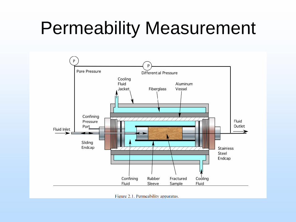
Permeability Measurement

Triaxial Test
• Core sample is held in loading frame • Variable axial load applied • Confining pressure and pore pressure
hydraulically generated • Stresses, strains, pressures measured • Axial load increased until failure • Stress/strain data gives Young’s modulus • Axial/radial strain data gives Poisson’s ratio

Triaxial Test – Loading Frame

Triaxial test - Schematic

Methodology, Simulations • Start with base simulator - TOUGH2-CSM,
TOUGH2-FLAC • Formulate and code simulator modifications • CSM simulators are run on our 32-node cluster
computer (EMGCluster) - 16 with 16 proc./node, 24 GB memory/node - 16 with 24 proc./node, 32 GB memory/node
12
TOUGH2-FLAC • Linkage of TOUGH2-MP, FLAC3D • TOUGH2-MP: simulates multiphase,
multicomponent fluid and heat flow in fractured and porous rock
• FLAC3D: simulates rock mechanics with thermo- and hydro-mechanical effects
13

TOUGH2-CSM • Simulates fluid and heat flow and geomechanics
in porous and fractured media • Based on TOUGH2-MP parallel code • Fluid property modules: EOS2 (H2O-CO2);
ECO2N (H2O-NaCl-CO2) • Mean Stress Formulation to simulate rock
deformation (geomechanics) • Developed to simulate CO2 sequestration in deep
saline aquifers
14
Expected Outcomes
• Correlations of fracture permeability to effective stress and pore pressure for CO2 injection
• Correlations between confining stress, fluid pressure, and fracture initialization during CO2 injection
• Mathematical model of fracture growth and propagation for potential leakage
15

Expected Outcomes, continued
• Validated THM reservoir simulator with fracture initiation and propagation model, plus fracture permeability correlations
• Modeling and optimization scheme to maximize storage capacity and to identify leakage locations, times, and rates using THM reservoir simulator
16

17
Organization Chart YSW: Yu-Shu Wu XY: Xiaolong Yin PHW: Philip H. Winterfeld JR: Jonny Rutqvist TK: Tim Kneafsey CSM: Colorado School of Mines LBNL: Lawrence Berkeley National Laboratory

18
Communication Plan
• CSM is the lead organization • Project PI, Dr. Yu-Shu Wu, is also a Guest
Scientist at LBNL • He will work at LBNL several days per month
over the duration of the project • Monthly teleconferences and routine
communication by phone or email will be held among the PI and CO-PI’s
Task/Subtask Breakdown
19
• Seven tasks
• Task 1 is Project Management
Task 2
20
• 2: Laboratory studies of effects of geomechanics on CO2 flow and transport properties in fractured rock - correlate effective stress to fracture effective
permeability and porosity
• 2.1: Obtaining appropriate rock cores, rock characterization, and rock preparation - commercial sources, industrial partners, in-house - determine physical, mineralogical properites - split perpendicularly (~ two halves)
Task 2, continued
21
• 2.2: Permeability vs. effective stress - install split core in permeability apparatus - offset core halves to provide fracture aperture - X-ray core for aperture map - saturate core with brine - measure permeability versus effective stress with
flowing brine
• 2.3: SC CO2 effective permeability vs. effective stress - similar to 2.2, use super critical CO2
Task 3
22
• 3: Laboratory studies of CO2 and brine injection-induced fracturing – obtain fracture initiation condition due to CO2 injection – determine dynamics of fracture propagation
• 3.1: Fracture initiation using brine
- characterize fracture initiation pressure as function of stress, brine leakoff, pressure increase rate
- under unconfined and triaxial stress conditions - X-ray CT for sample inspection for fractures, before and
after experiments

Task 3, continued
23
• 3.2: Fracture initiation using CO2 - similar to 3.1, use CO2 instead of brine - heat effects are considered
• 3.3: Dimensionless numbers / scaling for reservoir-scale
fracture propagation - field-scale from laboratory-scale apparatus

Task 4
24
• 4: Development of CO2 flow and geomechanics-coupled models for modeling fracturing growth – develop and implement approaches for modeling fracture
propagation in TOUGH-CSM, TOUGH-FLAC
• 4.1: Determination of constitutive correlations for fracture initiation, and growth and propagation - literature review, determine modifications needed to
simulate fracture initiation

Task 4, continued
25
• 4.2: Modification of TOUGH2-CSM to calculate stress tensor components
• 4.3: Modification of TOUGH2-CSM to simulate fracture initiation, and growth and propagation
• 4.4: Modification of TOUGH2-FLAC to simulate fracture initiation, and growth and propagation
• 4.5: Testing and verification of TOUGH2-CSM and TOUGH-FLAC for fracture propagation modeling - analytical solutions, benchmark problems, comparisons
to other codes

Task 5
26
• 5: Incorporation of CO2 injection-enhanced property and fracture correlations/models into reservoir simulators – Fracture permeability versus stress
• 5.1: Modification of TOUGH2-CSM to model stress-dependent fracture permeability
• 5.2: Modification of TOUGH2-FLAC to model stress-dependent fracture permeability
• 5.3: Testing and verification of TOUGH2-CSM and TOUGH-FLAC for modeling injection-induced property changes in fractured reservoirs
Task 6
27
• 6: Concept and flow-mechanics coupled model validation using field data of stress and rock deformation measurement
• 6.1: Validation of model for stress induced permeability changes in single fracture – Model Task 2 experiments to validate fracture permeability
models
• 6.2: Verification and validation of models for fluid driven fracture propagation under triaxial stress conditions – Same for Task 3 experiments

Task 6, continued
28
• 6.3: Validation against deep fracture zone opening and surface uplift at In Salah – reproduce the shape and magnitude of the surface uplift
• 6.4: Application of models to a generic large-scale
sequestration site – study pressure and temperature effects on stress – plus impacts on: fractured reservoir permeability and
injectivity; fracture porosity on storage volume; leakage potential by a breach of the caprock through hydraulic fracturing.

Task 7
29
• 7: Development of modeling tools for identification of potential leakage risks – inverse model, coupled to software – maximize storage capacity, predict performance, and
determine leakage location
• 7.1: Construction of an inverse modeling model and optimization scheme – sensitivity analysis of factors that affect CO2 leakage – develop an optimized inverse modeling process – couple the inverse model to reservoir ones

Task 7, continued
30
• 7.2: Validation of the coupled model
– analytical models, cases from literature
Deliverables / Milestones / Decision Points
31
• Decision points are made at end of each fiscal year of the proposed 3 year project
• The successful criteria for each task and subtask will be assessed during execution of the plan according to the milestone table
• Not anticipating any no-go decision points

Deliverables / Milestones / Decision Points, continued
32
Risk Matrix
33
• Main risk: lack of field studies or field in-situ stress and rock deformation data for CO2 injection and storage
• Mitigate risk: – extensive literature review for such data – communications with those experienced in
those areas for updated information – better measurements and data collections in
our laboratory studies

34
Proposed Schedule

35
Proposed Schedule, continued

Summary
• Research tasks have been defined and personnel assigned to them
• Work on tasks have begun
36