quality of service in ip networks quality of service in ip networks
TRANSCRIPT

1Presentation_ID © 1999, Cisco Systems, Inc.
Quality of Service inIP Networks
Quality of Service inIP Networks
Ivo Němeček,
Systems Engineer, Cisco Systems
Ivo Němeček,
Systems Engineer, Cisco Systems
2Ip_atm_qos_serv_0699 © 1999, Cisco Systems, Inc. www.cisco.com
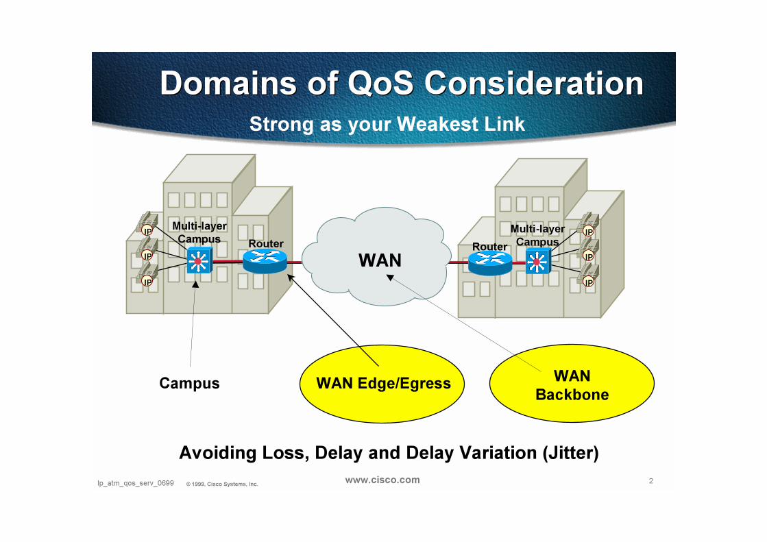
Domains of QoS Consideration Domains of QoS Consideration
WAN
Campus
RouterIP
IP
IP
IP
IP
IP
Multi-layer
Campus
Multi-layer
Campus
Strong as your Weakest Link
WAN Edge/Egress WAN
Backbone
Router
Avoiding Loss, Delay and Delay Variation (Jitter)
3Ip_atm_qos_serv_0699 © 1999, Cisco Systems, Inc. www.cisco.com
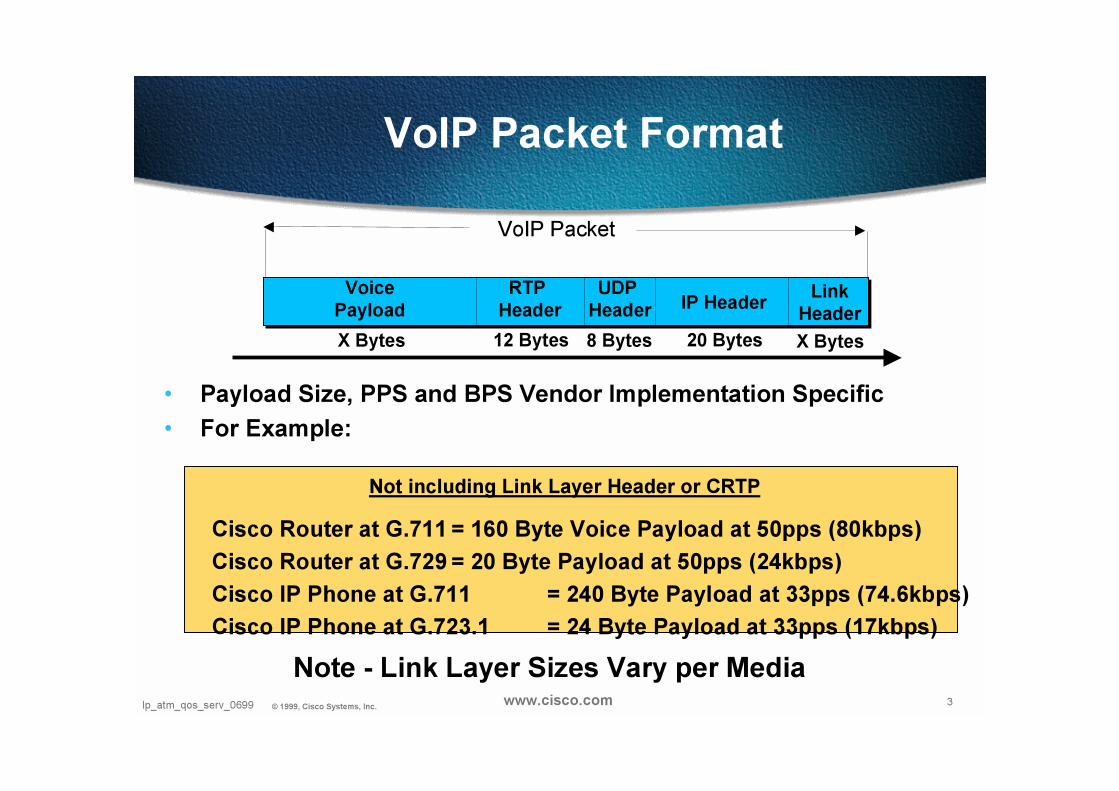
VoIP Packet Format
• Payload Size, PPS and BPS Vendor Implementation Specific
• For Example:
Cisco Router at G.711 = 160 Byte Voice Payload at 50pps (80kbps)
Cisco Router at G.729 = 20 Byte Payload at 50pps (24kbps)
Cisco IP Phone at G.711 = 240 Byte Payload at 33pps (74.6kbps)
Cisco IP Phone at G.723.1 = 24 Byte Payload at 33pps (17kbps)
Link
HeaderIP Header
UDP
Header
RTP
Header
VoIP Packet
X Bytes20 Bytes8 Bytes12 Bytes
Voice
Payload
X Bytes
Note - Link Layer Sizes Vary per Media
Not including Link Layer Header or CRTP
4Ip_atm_qos_serv_0699 © 1999, Cisco Systems, Inc. www.cisco.com
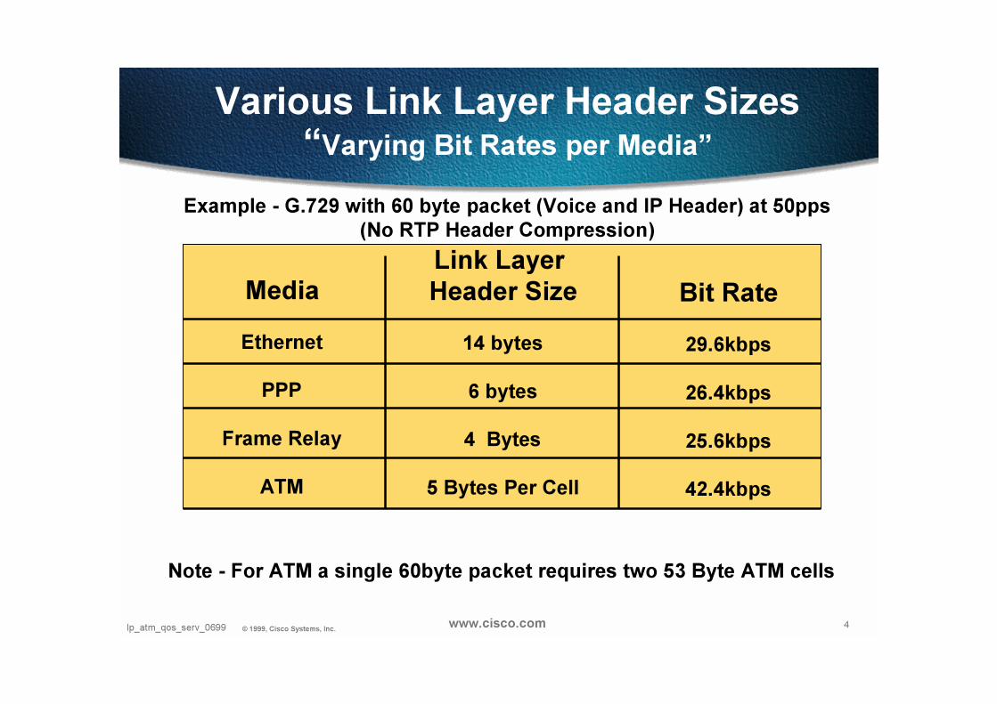
Various Link Layer Header Sizes“Varying Bit Rates per Media”
Media
Ethernet
PPP
Frame Relay
ATM
Link Layer
Header Size
14 bytes
6 bytes
4 Bytes
5 Bytes Per Cell
Bit Rate
29.6kbps
26.4kbps
25.6kbps
42.4kbps
Example - G.729 with 60 byte packet (Voice and IP Header) at 50pps
(No RTP Header Compression)
Note - For ATM a single 60byte packet requires two 53 Byte ATM cells

5Ip_atm_qos_serv_0699 © 1999, Cisco Systems, Inc. www.cisco.com
IP
IP
7500
Branch Office’s
Frame
Relay
Headquarters
IPSiSi
IPCatalyst
6500
RegionalOffice7200
128 kbps
T1
ATM
Pt to Pt
256kbps
IP
High Speed
WAN Backbone
> 2 mbps
Low Speed Low Speed
Remote SitesRemote Sites
WAN ProvisioningWAN Provisioning
and Designand Design
Low SpeedLow Speed
Central SiteCentral Site
High SpeedHigh Speed
BackboneBackbone
CampusCampus
26/36/38
26/36/38
26/36/38
Applying Proper Tools in Proper Location
Case Study:End to End Quality of Service
Case Study:End to End Quality of Service
•• Most NeedMost Need
“Special” Focus on WAN Edge
6Ip_atm_qos_serv_0699 © 1999, Cisco Systems, Inc. www.cisco.com
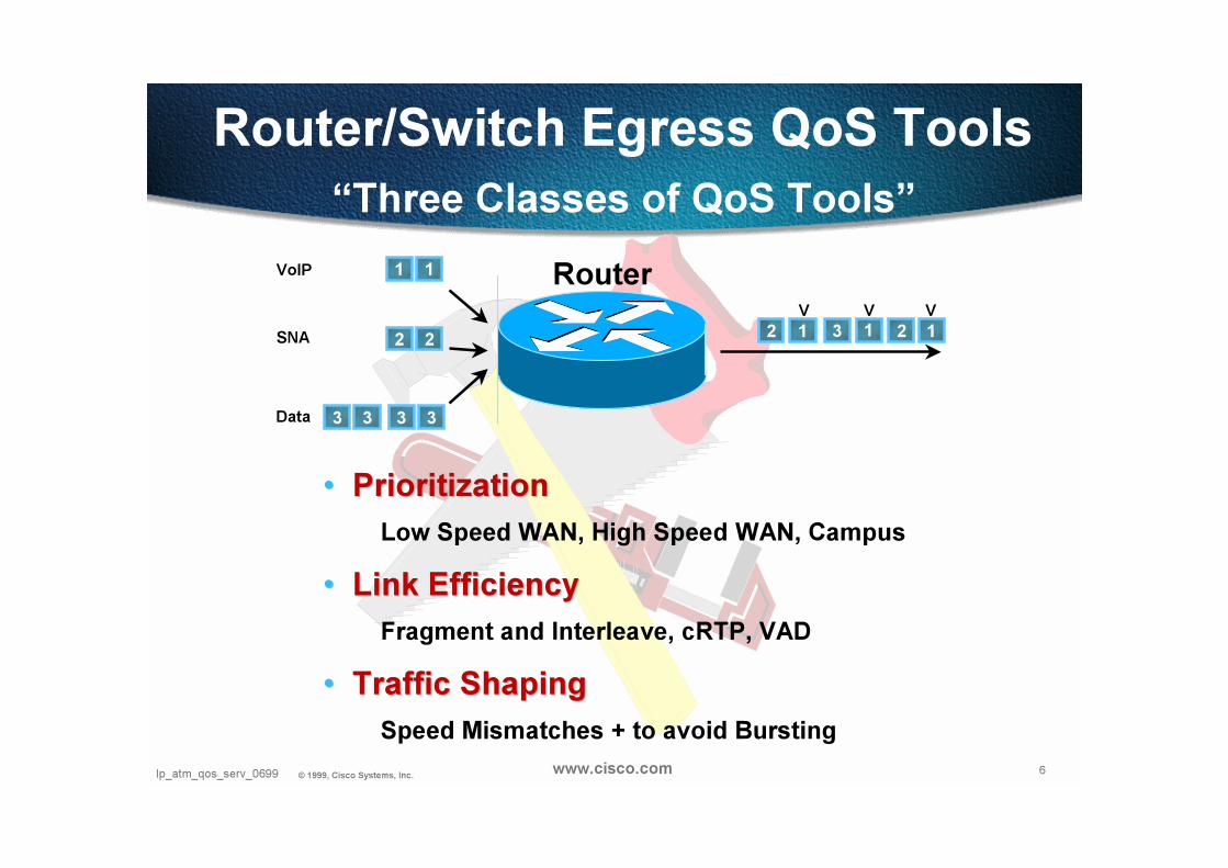
Router/Switch Egress QoS Tools
•• PrioritizationPrioritization
Low Speed WAN, High Speed WAN, Campus
•• Link EfficiencyLink Efficiency
Fragment and Interleave, cRTP, VAD
•• Traffic ShapingTraffic Shaping
Speed Mismatches + to avoid Bursting
“Three Classes of QoS Tools”
Router
3 33 3
2 22 1 3 2 11
1 1VoIP
SNA
Data
VVV
7Ip_atm_qos_serv_0699 © 1999, Cisco Systems, Inc. www.cisco.com
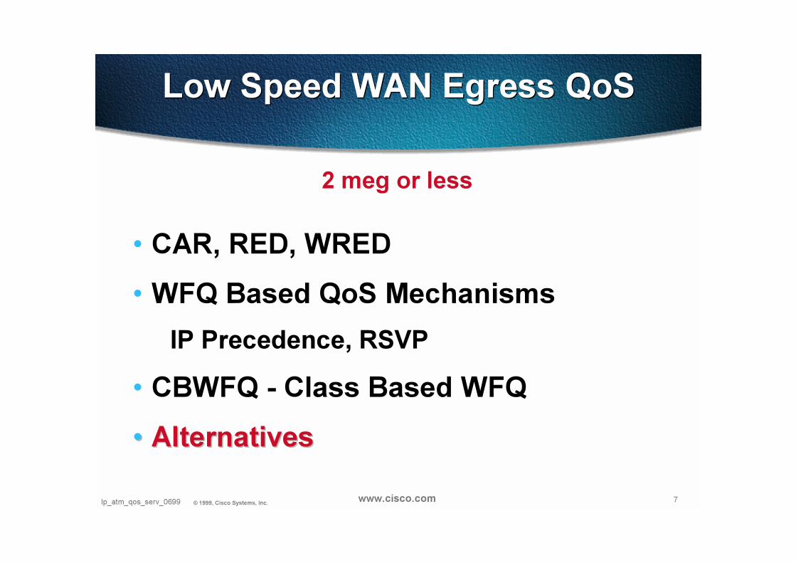
Low Speed WAN Egress QoSLow Speed WAN Egress QoS
• CAR, RED, WRED
• WFQ Based QoS Mechanisms
IP Precedence, RSVP
• CBWFQ - Class Based WFQ
•• AlternativesAlternatives
2 meg or less

8Presentation_ID © 1999, Cisco Systems, Inc. 8Presentation_ID © 1999, Cisco Systems, Inc. www.cisco.com
CAR CAR

9Ip_atm_qos_serv_0699 © 1999, Cisco Systems, Inc. www.cisco.com
Committed Access Rate (CAR)
• CAR is IOS Feature name
• Two functions
Packet Classification Packet Classification —
sort a subset of traffic matching some
complex criterion
Traffic Conditioning Traffic Conditioning
rate measurement, rate limiting, packet
marking (IP Precedence rewrite)
10Ip_atm_qos_serv_0699 © 1999, Cisco Systems, Inc. www.cisco.com
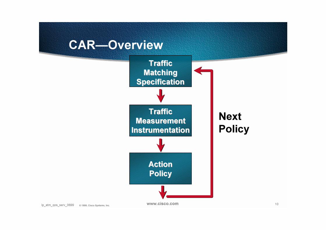
CAR—Overview
TrafficTraffic
MatchingMatching
SpecificationSpecification
Next
Policy
ActionAction
PolicyPolicy
TrafficTraffic
MeasurementMeasurement
InstrumentationInstrumentation
11Ip_atm_qos_serv_0699 © 1999, Cisco Systems, Inc. www.cisco.com
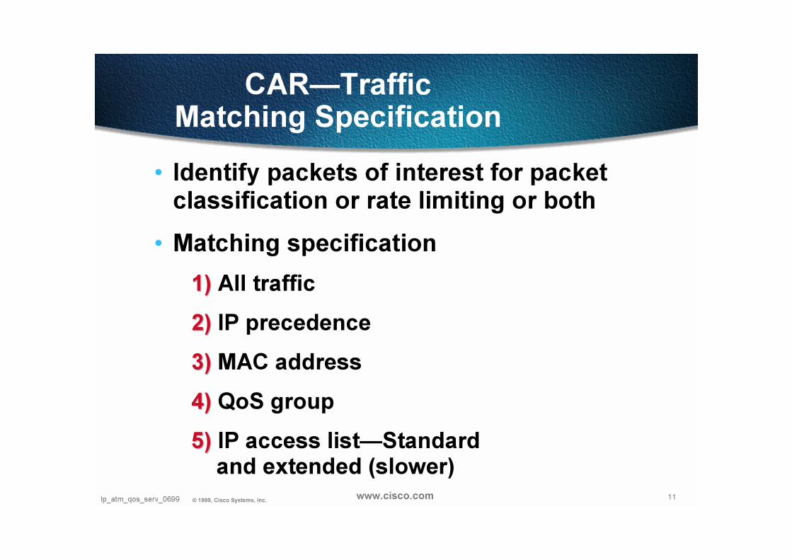
CAR—Traffic Matching Specification
• Identify packets of interest for packet classification or rate limiting or both
• Matching specification
1)1) All traffic
2)2) IP precedence
3)3) MAC address
4)4) QoS group
5)5) IP access list—Standard and extended (slower)
12Ip_atm_qos_serv_0699 © 1999, Cisco Systems, Inc. www.cisco.com
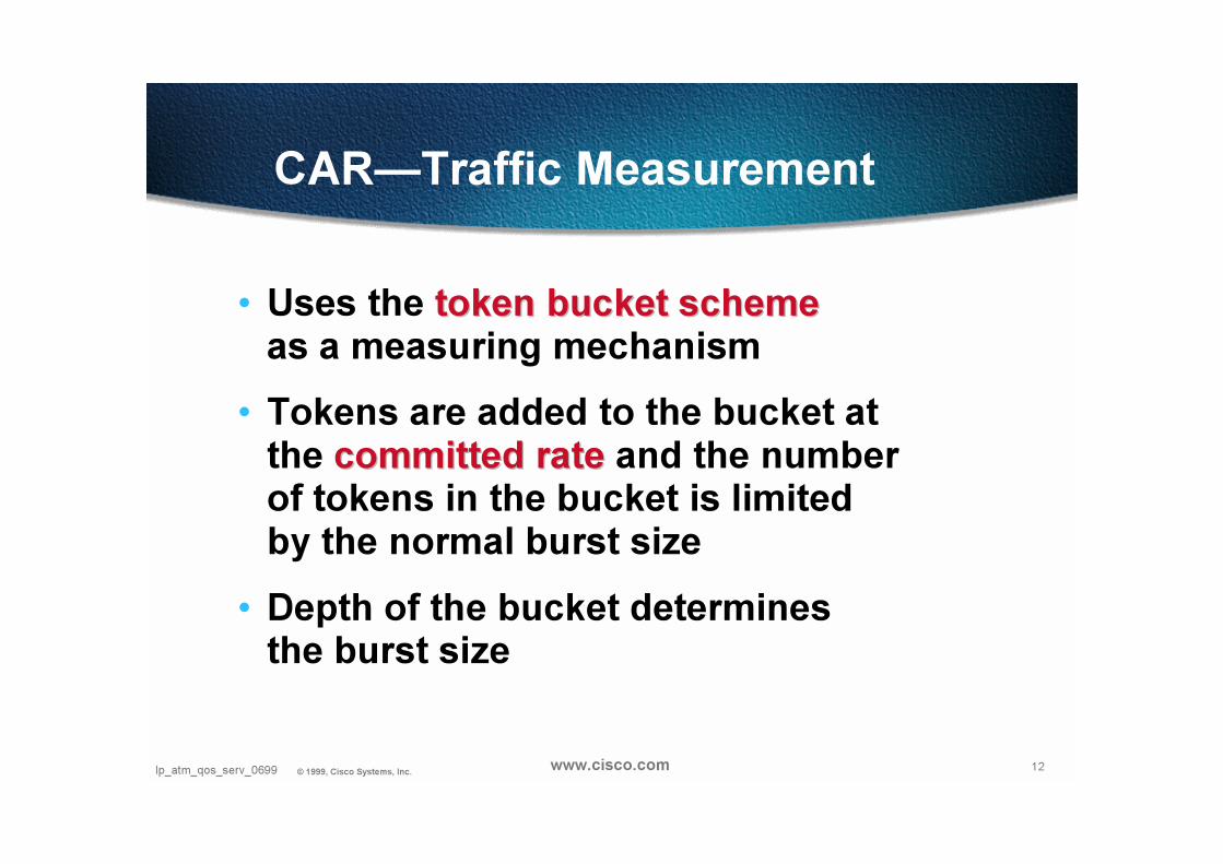
CAR—Traffic Measurement
• Uses the token bucket schemetoken bucket schemeas a measuring mechanism
• Tokens are added to the bucket at the committed ratecommitted rate and the number of tokens in the bucket is limited by the normal burst size
• Depth of the bucket determines the burst size
13Ip_atm_qos_serv_0699 © 1999, Cisco Systems, Inc. www.cisco.com
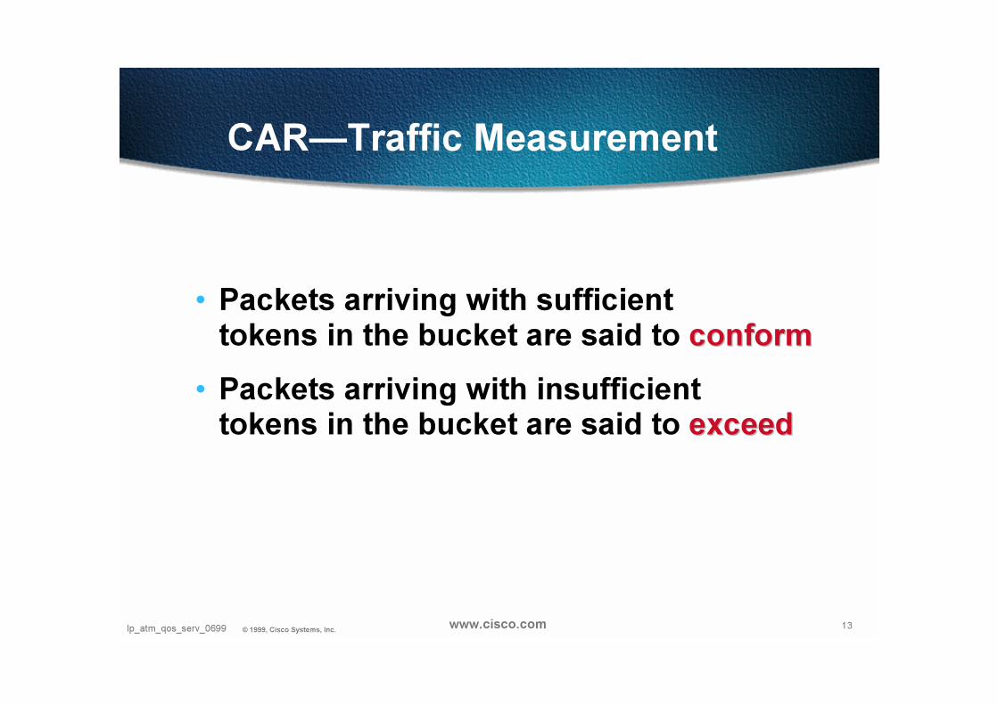
CAR—Traffic Measurement
• Packets arriving with sufficient tokens in the bucket are said to conformconform
• Packets arriving with insufficient tokens in the bucket are said to exceedexceed

14Ip_atm_qos_serv_0699 © 1999, Cisco Systems, Inc. www.cisco.com
CAR—Traffic Measurement
• Packets arriving exceeding the normal burst but fall within the extended burst limit are handled via a RED-like managed drop policy
• This reduces TCP Slow-Start oscillation
(When the exceed-action is to drop packets)
15Ip_atm_qos_serv_0699 © 1999, Cisco Systems, Inc. www.cisco.com
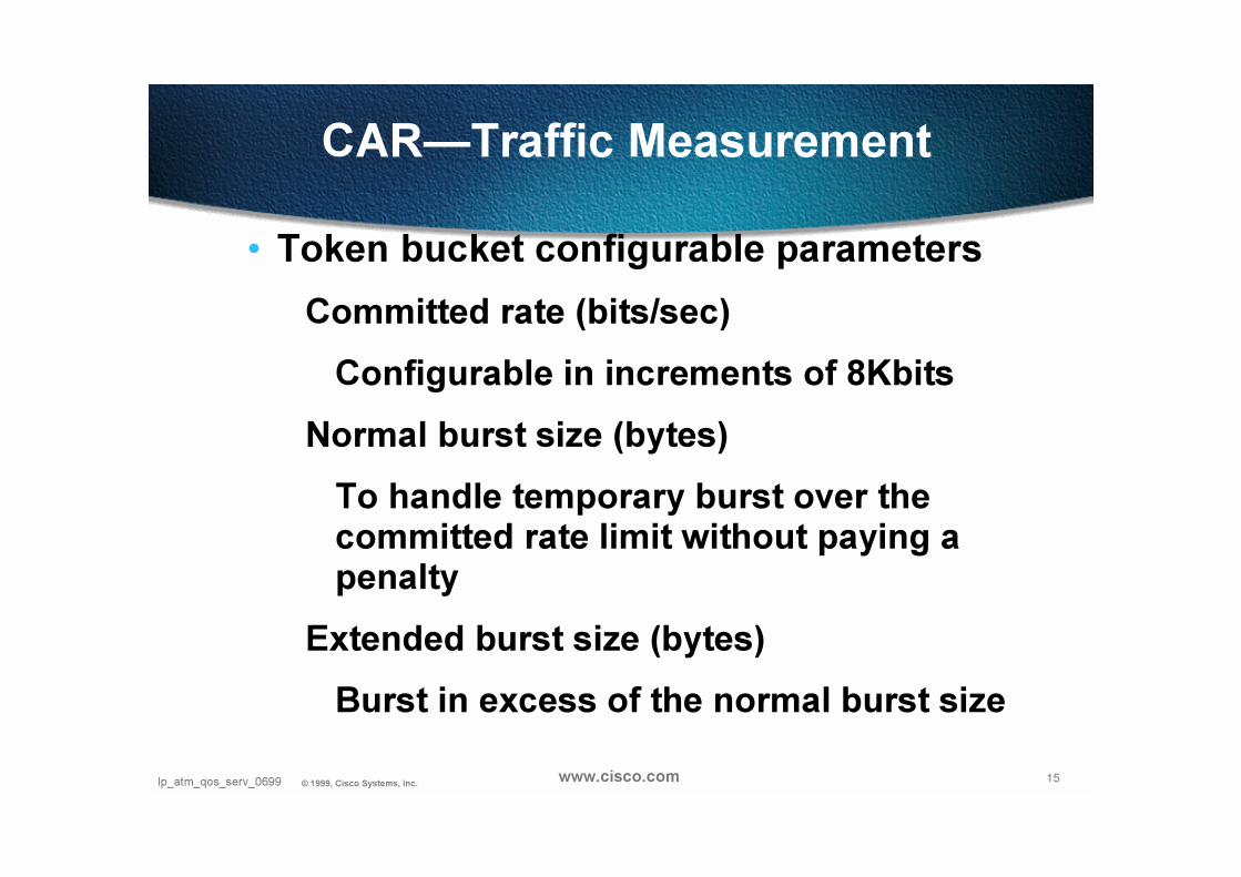
CAR—Traffic Measurement
• Token bucket configurable parameters
Committed rate (bits/sec)
Configurable in increments of 8Kbits
Normal burst size (bytes)
To handle temporary burst over the committed rate limit without paying a penalty
Extended burst size (bytes)
Burst in excess of the normal burst size
16Ip_atm_qos_serv_0699 © 1999, Cisco Systems, Inc. www.cisco.com
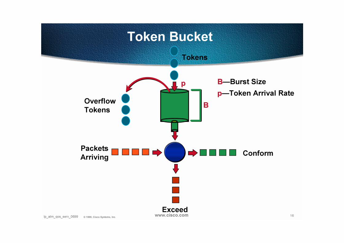
Token Bucket
pp
Tokens
BBOverflowTokens
PacketsArriving
Conform
Exceed
BB—Burst Size
pp—Token Arrival Rate

17Ip_atm_qos_serv_0699 © 1999, Cisco Systems, Inc. www.cisco.com
Extended Burst
Exceed %
100
BucketDepth
Extended
Burst
Normal
Burst

18Ip_atm_qos_serv_0699 © 1999, Cisco Systems, Inc. www.cisco.com
CAR—Action Policies
• Configurable actions
Transmit
Drop
Continue (go to the next rate-limit in the list)
Set precedence and transmit (rewrite the IP precedence bits and transmit)
Set precedence and continue (rewrite the IP precedence bits and go to the next rate-limit in the list)
19Ip_atm_qos_serv_0699 © 1999, Cisco Systems, Inc. www.cisco.com
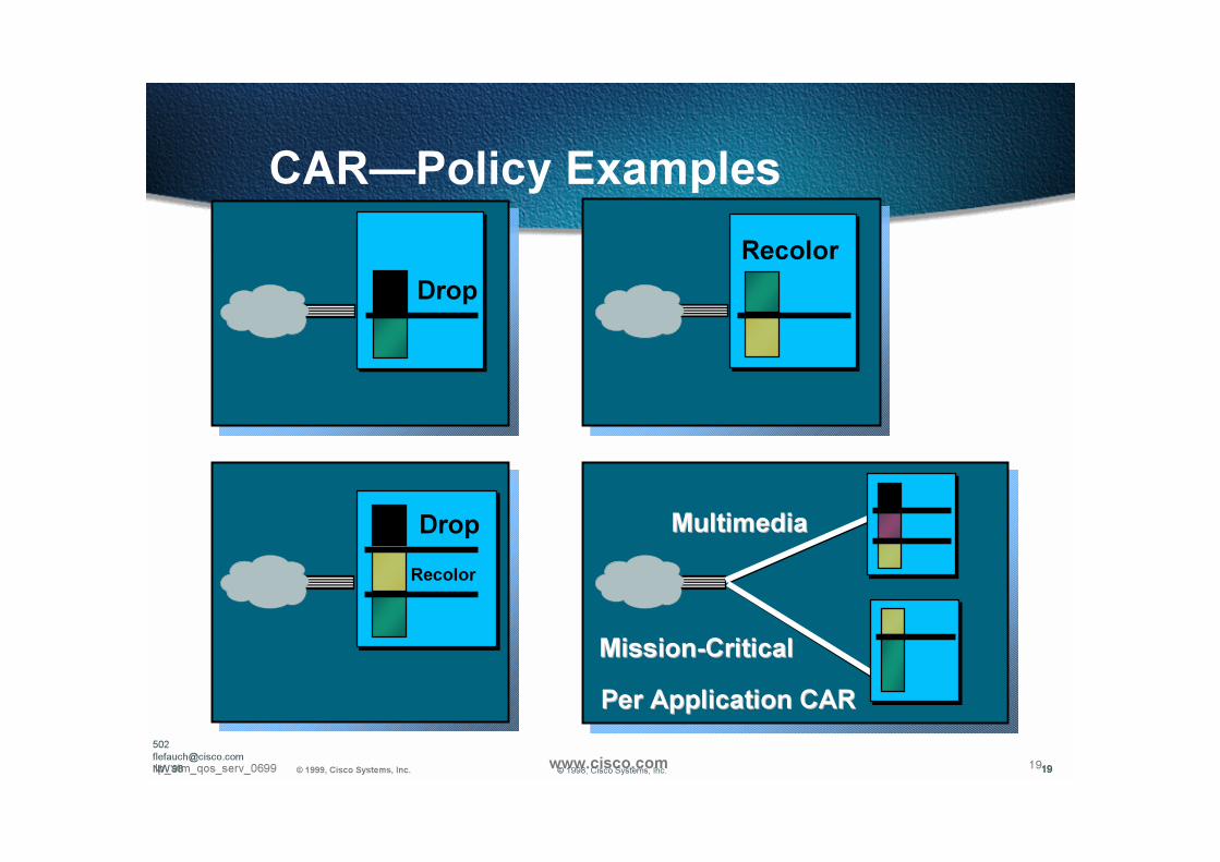
CAR—Policy Examples
Drop
Drop
Per Application CARPer Application CAR
MultimediaMultimedia
MissionMission--CriticalCritical
Recolor
Recolor
19© 1998, Cisco Systems, Inc.
502
NW’98 19
20Ip_atm_qos_serv_0699 © 1999, Cisco Systems, Inc. www.cisco.com
Packet Marking
• Also known as colouring or labeling of packets
• Partition network traffic into multiple traffic classes or Class of Service (CoS)
• Marking can be done using several methods
CARCAR
QoS Policy Propagation via BGPQoS Policy Propagation via BGP
Policy routingPolicy routing
21Ip_atm_qos_serv_0699 © 1999, Cisco Systems, Inc. www.cisco.com
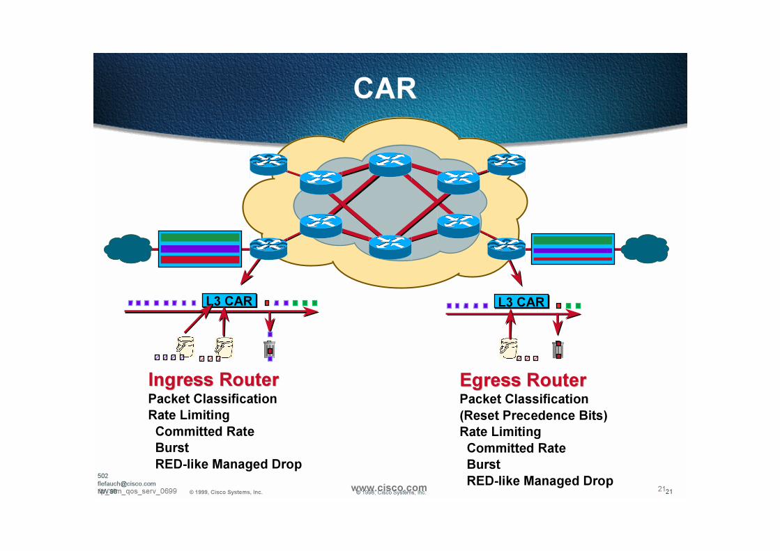
CAR
Ingress RouterIngress RouterPacket Classification
Rate Limiting
Committed Rate
Burst
RED-like Managed Drop
Egress RouterEgress RouterPacket Classification
(Reset Precedence Bits)
Rate Limiting
Committed Rate
Burst
RED-like Managed Drop
L3 CAR L3 CAR
502
NW’98 21© 1998, Cisco Systems, Inc.

22Presentation_ID © 1999, Cisco Systems, Inc. 22Presentation_ID © 1999, Cisco Systems, Inc. www.cisco.com
RED RED
23Ip_atm_qos_serv_0699 © 1999, Cisco Systems, Inc. www.cisco.com
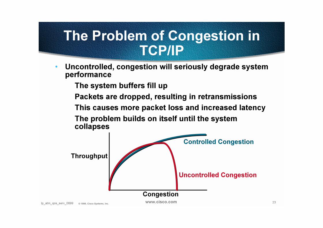
The Problem of Congestion in TCP/IP
• Uncontrolled, congestion will seriously degrade system performance
The system buffers fill up
Packets are dropped, resulting in retransmissions
This causes more packet loss and increased latency
The problem builds on itself until the system collapses
Throughput
Congestion
Controlled CongestionControlled Congestion
Uncontrolled CongestionUncontrolled Congestion

24Ip_atm_qos_serv_0699 © 1999, Cisco Systems, Inc. www.cisco.com
REDQueue
QueuePointer
• Without RED when the queue fills up all packets that arrive are dropped—Tail dropTail drop
• With RED as opposed to doing a tail drop the router monitors the average queue average queue
sizesize
using randomization chooses flows to notify that a congestion is impending
PacketsArriving
24© 1998, Cisco Systems, Inc.
25Ip_atm_qos_serv_0699 © 1999, Cisco Systems, Inc. www.cisco.com
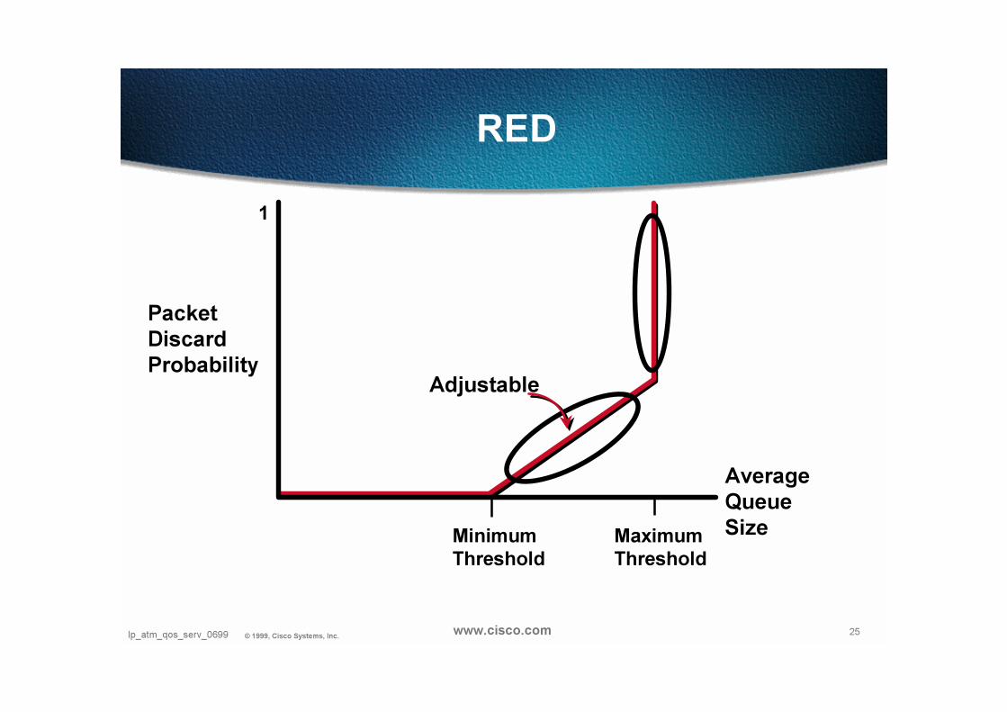
RED
Packet DiscardProbability
AverageQueue SizeMaximum
Threshold
Minimum
Threshold
Adjustable
1
26Ip_atm_qos_serv_0699 © 1999, Cisco Systems, Inc. www.cisco.com
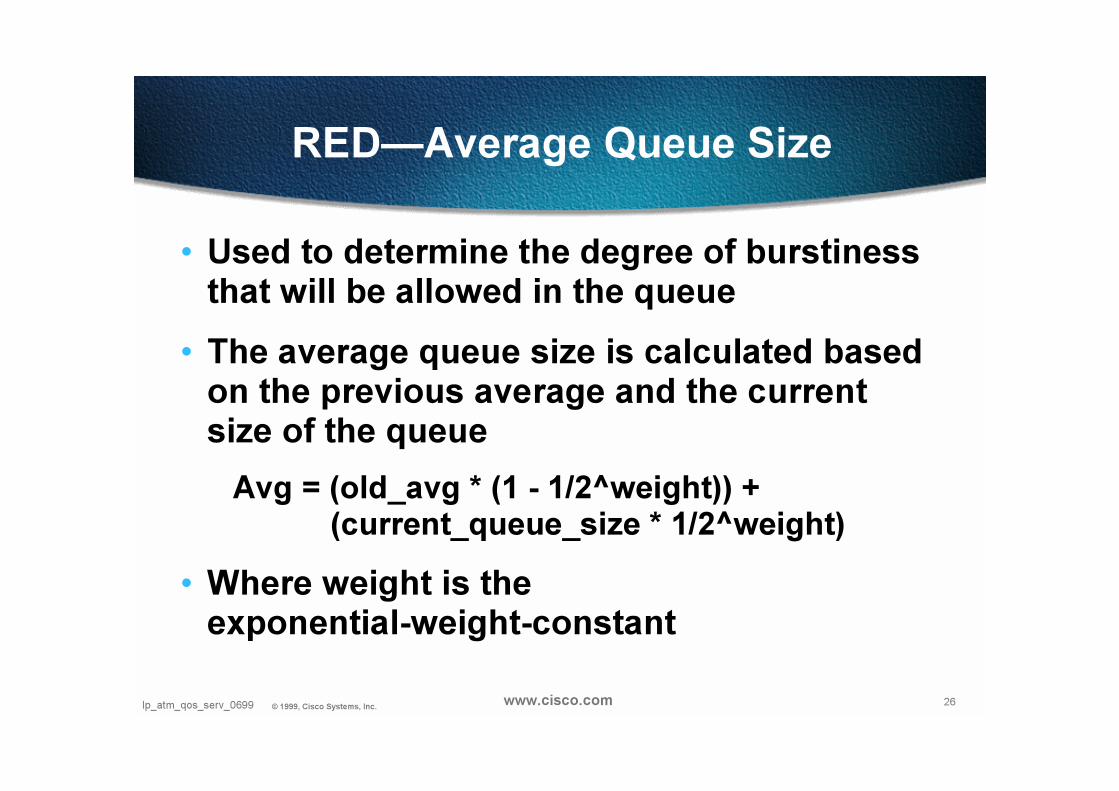
RED—Average Queue Size
• Used to determine the degree of burstiness that will be allowed in the queue
• The average queue size is calculated based on the previous average and the current size of the queue
Avg = (old_avg * (1 - 1/2^weight)) +(current_queue_size * 1/2^weight)
• Where weight is the exponential-weight-constant

27Ip_atm_qos_serv_0699 © 1999, Cisco Systems, Inc. www.cisco.com
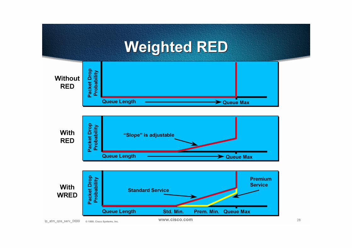
Weighted RED (WRED)
• WRED combines REDRED with IPIP PrecedencePrecedenceto implement multiple service classes
• Each service class has a defined min and max threshold, and drop rates
• In a congestion situation lower class traffic is throttled back first before higher class traffic
• RED is applied to all levels of traffic to manage congestion
28Ip_atm_qos_serv_0699 © 1999, Cisco Systems, Inc. www.cisco.com
Weighted REDWeighted RED
Packet
Dro
p
Pro
ba
bilit
y
Queue Length
“Slope” is adjustable
Queue Max
Packet
Dro
p
Pro
ba
bil
ity
Queue Length Queue Max
Packet
Dro
p
Pro
ba
bilit
y
Queue Length
Standard Service
Queue Max
Without
RED
With
RED
With
WRED
Premium
Service
Std. Min. Prem. Min.

29Ip_atm_qos_serv_0699 © 1999, Cisco Systems, Inc. www.cisco.com
Where/When Should I Use WRED?
• Congested long-haul links (e.g., trans-oceanic links)
• Where the bulk of your traffic is TCP as oppose to UDP
Remember only TCP will react to a packet Remember only TCP will react to a packet
drop UDP will notdrop UDP will not
30Presentation_ID © 1999, Cisco Systems, Inc. 30Presentation_ID © 1999, Cisco Systems, Inc. www.cisco.com
WFQ WFQ
31Ip_atm_qos_serv_0699 © 1999, Cisco Systems, Inc. www.cisco.com
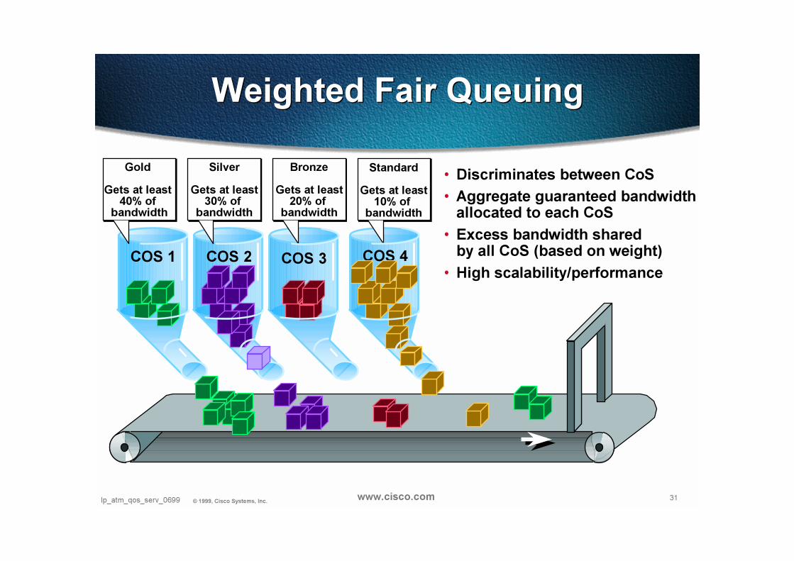
Weighted Fair QueuingWeighted Fair Queuing
• Discriminates between CoS
• Aggregate guaranteed bandwidthallocated to each CoS
• Excess bandwidth sharedby all CoS (based on weight)
• High scalability/performanceCOS 1 COS 2 COS 3 COS 4
Gold
Gets at least 40% of
bandwidth
Standard
Gets at least10% of
bandwidth
Silver
Gets at least30% of
bandwidth
Bronze
Gets at least20% of
bandwidth

32Ip_atm_qos_serv_0699 © 1999, Cisco Systems, Inc. www.cisco.com
(V)IP(V)IP (V)IP(V)IP
Packet Scheduling
• An algorithm that determines the order in which packets are sent out to the transmission link
• Examples of packet scheduling schemes
FIFO
Fair Queuing
Weighted Fair Queuing
RSPRSP
Cisco 7500
VIPVIPVIPVIP

33Ip_atm_qos_serv_0699 © 1999, Cisco Systems, Inc. www.cisco.com
Weighted Fair Queuing (WFQ)
• Multiple “logical” queues
• Assign a weight for each queue
• Backlog queues are served in proportion to their weight
• Ideal WFQ
packet of a queue transmitted at least at same time it would be transmitted if it had its own interface with speed of queue service rate
(V)IP(V)IP VIPVIP(V)IP(V)IP
11 22 33
RSPRSP
Cisco 7500

34Ip_atm_qos_serv_0699 © 1999, Cisco Systems, Inc. www.cisco.com
IP Packet
Data
3 bit
Precedence
Field
ToS Field
IP Precedence“Controlling WFQ’s De-queuing Behavior”
IP PrecedenceNot a QoS Mechanism turned on in the router“In Band” QoS Signaling - Set in the End Point
4096
(1 + IP Prec)Weight =
IP Prec Weight
0 40961 2048
2 1365
3 1024
4 819
5 6826 585
7 512

35Ip_atm_qos_serv_0699 © 1999, Cisco Systems, Inc. www.cisco.com
Weighted Fair Queuing (WFQ)Treats Flows with same IP Precedence Equally
500kbps flowTransmit
Scheduling
24kbps Voice
flow
Classify
1 De-
queue
Interface Queues
Dynamic Queue Per Flow
24kbps flow gets 28kbps(only needs 24kbps)
500kbps flow gets 28kbps
Therefore = “Fair”
35
56kbps
Line Speed
Processor
22 2 2 12
When Congestion Exists
Queues share Bandwidth Equally
ie. “Fair Queuing” in a TDM Fashion
“Not effective when MANY flows”“Not effective when MANY flows”
2 22 2
1 1
High Speed Input
Ethernet T1 etc.
Low Speed Output
56kbps
2 1 2 2 11
Router Queue Structure
Default on links 2meg or less

36Ip_atm_qos_serv_0699 © 1999, Cisco Systems, Inc. www.cisco.com
Why Use WFQ?
• Provides relative bandwidth guarantees
Fair Queuing (FQ)Fair Queuing (FQ) allocates equal share
of bandwidth to each active queue
Weighted Fair Queuing (WFQ)Weighted Fair Queuing (WFQ) allows
for unequal allocation of bandwidth
37Ip_atm_qos_serv_0699 © 1999, Cisco Systems, Inc. www.cisco.com
Why Use WFQ?
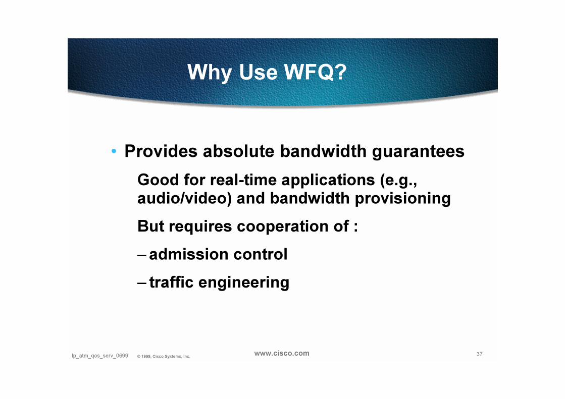
• Provides absolute bandwidth guarantees
Good for real-time applications (e.g., audio/video) and bandwidth provisioning
But requires cooperation of :
– admission control
– traffic engineering
38Ip_atm_qos_serv_0699 © 1999, Cisco Systems, Inc. www.cisco.com
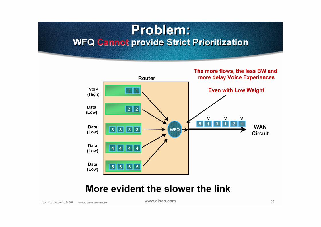
Problem:WFQ Cannot provide Strict Prioritization
Problem:WFQ CannotCannot provide Strict Prioritization
WFQ
Router
3 33 3
2 2
5 1 3 2 11
1 1VoIP
(High)
Data
(Low)
Data
(Low)
VVV
4 44 4Data
(Low)
5 55 5Data
(Low)
WAN
Circuit
The more flows, the less BW and The more flows, the less BW and
more delay Voice Experiencesmore delay Voice Experiences
Even with Low WeightEven with Low Weight
More evident the slower the link

39Ip_atm_qos_serv_0699 © 1999, Cisco Systems, Inc. www.cisco.com
IP Precedence
Calculating given Flow BW based on IP Precedence under congestion
Individual Flow “Parts” = 1 + IP Precedence
IP Precedence Flow “Parts”
0 1
1 2
2 33 4
4 5
5 6
6 7
7 8
Flow A BWFlow A BW = Flow A “Parts”
Sum of all Flow “Parts”Circuit BWX( )

40Ip_atm_qos_serv_0699 © 1999, Cisco Systems, Inc. www.cisco.com
IP PrecedenceFlow BW Calculation Example
Flow A BWFlow A BW = Flow A “Parts”
Sum of all Flow “Parts”Circuit BWX( )
Example A
56kbps link
2 - VoIP Flows A+B at 24kbps (IP Prec 0)
2 - FTP flows at 56kbps (IP Prec 0)
14kbps14kbps = X 56kbps1
4)(
14kbps NOTNOT suitable for a 24kbps flow
Example of many Flows with WFQ andequal Precedence flows
Example B
56kbps link
2 - VoIP Flows A+B at 24kbps (IP Prec 5)
2 - FTP flows at 56kbps (IP Prec 0)
24kbps24kbps = X 56kbps6
14)(
24kbps SUITABLESUITABLE for a 24kbps flow
WFQ preferring IP Precedence Weighted “Fair” Queuing
41Ip_atm_qos_serv_0699 © 1999, Cisco Systems, Inc. www.cisco.com
IP PrecedenceNo Admission Control
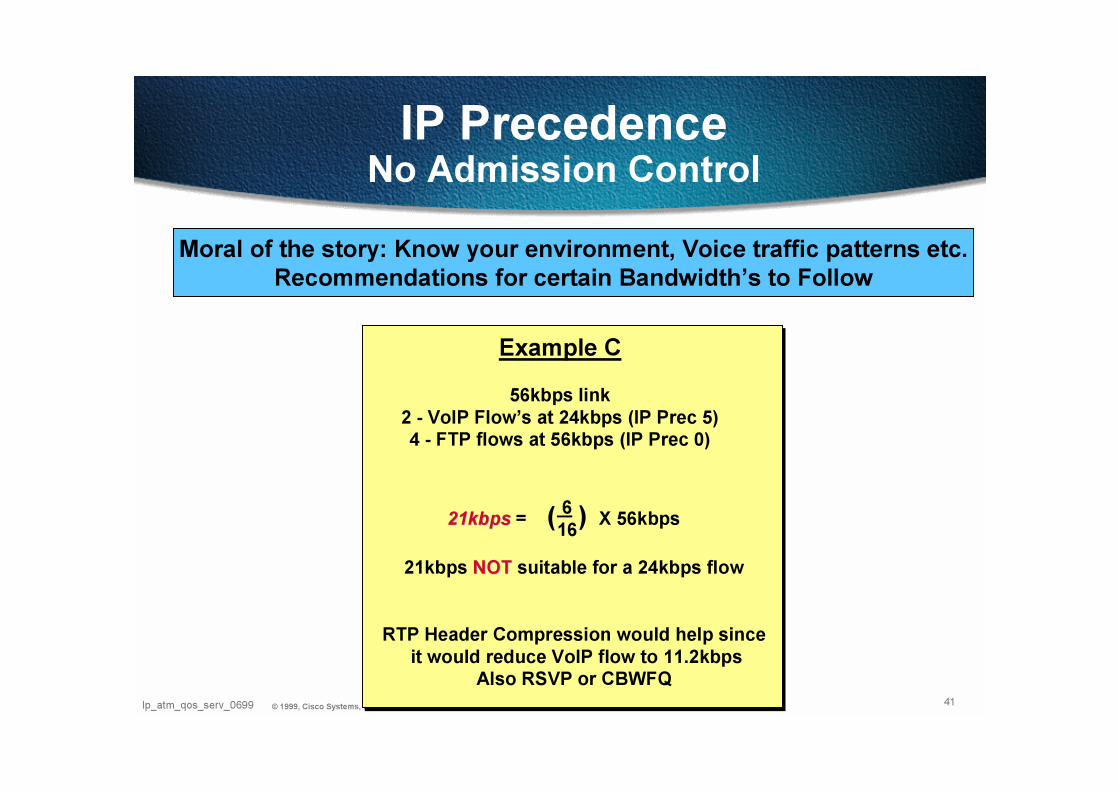
Moral of the story: Know your environment, Voice traffic patterns etc.Recommendations for certain Bandwidth’s to Follow
Example C
56kbps link
2 - VoIP Flow’s at 24kbps (IP Prec 5)4 - FTP flows at 56kbps (IP Prec 0)
21kbps21kbps = X 56kbps6
16)(
21kbps NOT NOT suitable for a 24kbps flow
RTP Header Compression would help since
it would reduce VoIP flow to 11.2kbpsAlso RSVP or CBWFQ

42Ip_atm_qos_serv_0699 © 1999, Cisco Systems, Inc. www.cisco.com
Options - Priority QueuingOptions - Priority Queuing
interface Serial0/0.1 point-to-point
ip address 10.1.1.1 255.255.255.0
ip mtu 300
frame-relay interface-dlci 100
class voice64
!
map-class frame-relay voice64
frame-relay cir 56000
frame-relay bc 1000
no frame-relay adaptive-shaping
frame-relay priority-group 1
!
accessaccess--list 101 permitlist 101 permit udpudp any any range 16384 16484 precedence criticalany any range 16384 16484 precedence critical
access-list 101 permit tcp any any eq 1720
access-list 101 permit tcp any any range 11000 12000
access-list 106 permit icmp any any
priority-list 1 protocol ip low list 106
prioritypriority--list 1 protocollist 1 protocol ipip mediummedium tcptcp 20652065
priority-list 1 protocol ip high list 101
Priority Queuing
Exhaustive Queuing
Mechanism
De-
queue
Priority Queues
56kbps
Line Speed3 33 3
2 22 1 3 2 11
1 1VoIP
(High)
SNA (DLSw)
(Medium)
Data
(Low)
VoIP
SNA (DLSw)
Issues Issues -- Cannot run with FRF.12 or MLPPPCannot run with FRF.12 or MLPPP
Warning Warning -- IP MTU Size Reduction Breaks ThingsIP MTU Size Reduction Breaks Things
Less than 600bytes breaks IP Phone TFTP downloadLess than 600bytes breaks IP Phone TFTP download
other protocols still can cause delayother protocols still can cause delay

43Ip_atm_qos_serv_0699 © 1999, Cisco Systems, Inc. www.cisco.com
WFQ
Router
3 33 3
2 24 3 2 1 1
1 1Voice
(Highest)
Data (High,
e.g. IP Prec 4)
Data (Medium,
e.g. IP Prec: 2)
VV
4 44 4
Data (Low, e.g.
IP Prec: 0)
PQ
WAN
Circuit
Exhaustive
Queuing
Obsoletes/Replaces the use of IP RTP Reserve
Prioritization - Queuing
PQ-WFQ (IP RTP Priority)PQ-WFQ (IP RTP Priority)
• Queue-limit for PQ is 64
No CLI to change
• Packets exceeding the allocated BW are dropped
• WFQ for:
non-RTP traffic
RTP traffic outside given port range
44Ip_atm_qos_serv_0699 © 1999, Cisco Systems, Inc. www.cisco.com
WFQ
Router
3 33 3
2 L
PQ - voice
WFQ - Data
4 44 4
PQ WAN Circuit
WFQ - Data
WFQ - Data
InterfaceHigh
Low
LMI
1 1
VV
4 3 2 4 3 L 1
V
1
V
L
1 1
VV
2
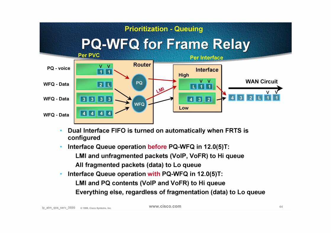
PQ-WFQ for Frame RelayPQ-WFQ for Frame Relay
• Dual Interface FIFO is turned on automatically when FRTS is configured
• Interface Queue operation before PQ-WFQ in 12.0(5)T:
LMI and unfragmented packets (VoIP, VoFR) to Hi queue
All fragmented packets (data) to Lo queue
• Interface Queue operation with PQ-WFQ in 12.0(5)T:
LMI and PQ contents (VoIP and VoFR) to Hi queue
Everything else, regardless of fragmentation (data) to Lo queue
Prioritization - Queuing
Per PVC Per Interface
45Ip_atm_qos_serv_0699 © 1999, Cisco Systems, Inc. www.cisco.com
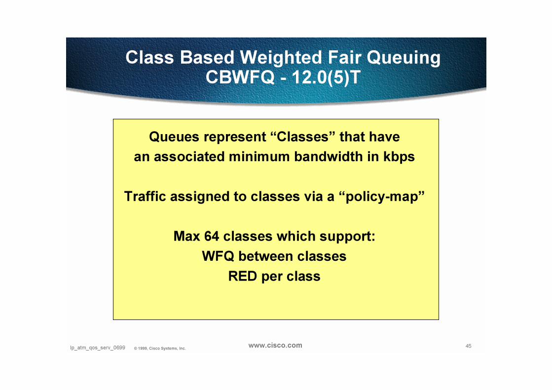
Class Based Weighted Fair QueuingCBWFQ - 12.0(5)T
Queues represent “Classes” that have
an associated minimum bandwidth in kbps
Traffic assigned to classes via a “policy-map”
Max 64 classes which support:
WFQ between classes
RED per class
46Ip_atm_qos_serv_0699 © 1999, Cisco Systems, Inc. www.cisco.com
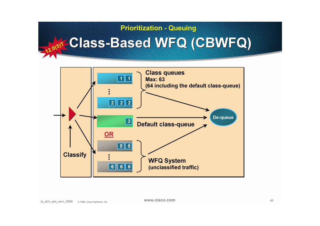
Prioritization - Queuing
Classify
De-queue
2 22
1 1
3
6 66
5 5
...
...
Default class-queue
WFQ System(unclassified traffic)
Class-Based WFQ (CBWFQ)Class-Based WFQ (CBWFQ)
OR
Class queuesMax: 63(64 including the default class-queue)
12.0(
5)T

47Ip_atm_qos_serv_0699 © 1999, Cisco Systems, Inc. www.cisco.com
Class Based Weighted Fair QueuingCBWFQ
47
47
Class Based WFQ
Classify
De-
queue
1 1
2 2
class-map data = 48kbbs
1 2 2 2 11128
kbps
class-map data
match input-interface Ethernet0/0
class-map class-default
match any
class-map voice
match access-group 101
!
!
policy-map WAN
class voice
bandwidth 80
class data
bandwidth 48
!
interface Serial0/1
ip address 10.1.6.2 255.255.255.0
bandwidth 128
no ip directed-broadcast
service-policy output WAN
!
access-list 101 permit ip any any precedence critical
class-map voice = 80kbbs
Any packet with IP Precedence = 5 gets
assigned to a class that will get a
minimum of 80kbps on a 128kbps circuit
NOTE: Does not work on subNOTE: Does not work on sub--interfaces interfaces
and with Frame Relay Traffic Shapingand with Frame Relay Traffic Shaping
48Ip_atm_qos_serv_0699 © 1999, Cisco Systems, Inc. www.cisco.com
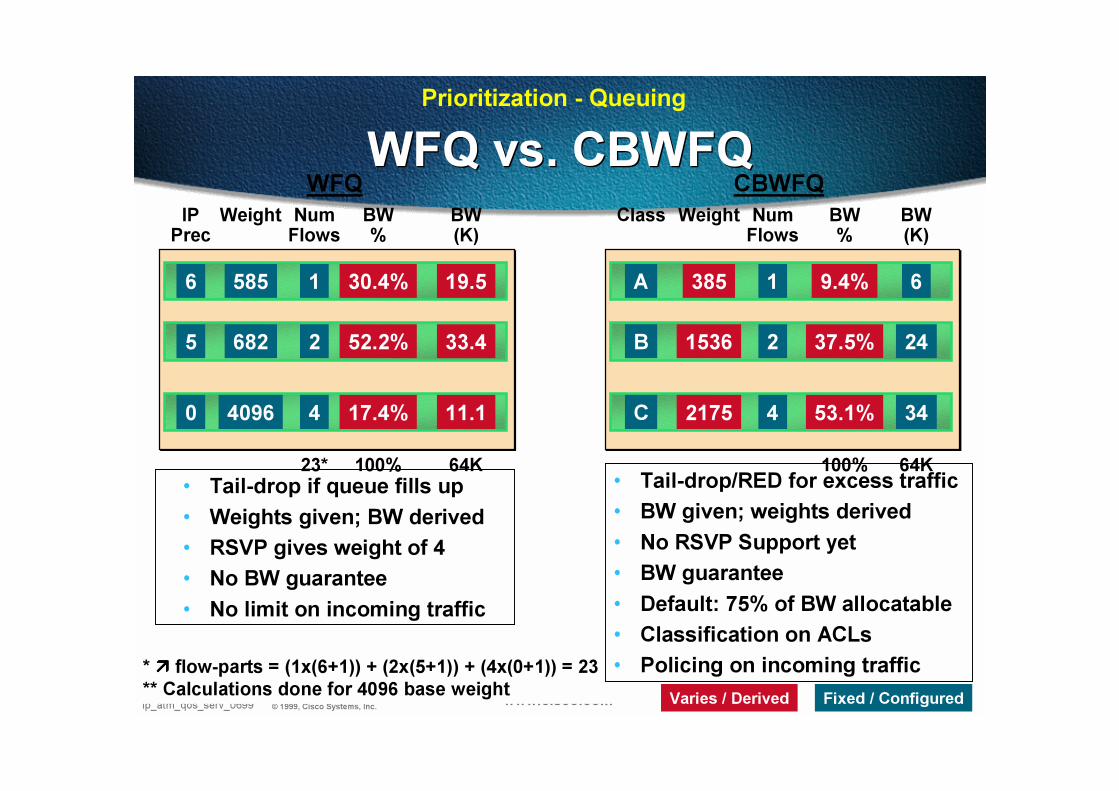
WFQ vs. CBWFQWFQ vs. CBWFQCBWFQWFQ
* ���� flow-parts = (1x(6+1)) + (2x(5+1)) + (4x(0+1)) = 23
** Calculations done for 4096 base weight
6
5
0
IPPrec
Weight
585
682
4096
NumFlows
1
2
4
19.5
33.4
11.1
BW (K)
30.4%
52.2%
17.4%
BW%
100% 64K23*
A
B
C
Class Weight
385
1536
2175
NumFlows
1
2
4
6
24
34
BW (K)
9.4%
37.5%
53.1%
BW%
100% 64K
Fixed / ConfiguredVaries / Derived
• Tail-drop if queue fills up
• Weights given; BW derived
• RSVP gives weight of 4
• No BW guarantee
• No limit on incoming traffic
• Tail-drop/RED for excess traffic
• BW given; weights derived
• No RSVP Support yet
• BW guarantee
• Default: 75% of BW allocatable
• Classification on ACLs
• Policing on incoming traffic
Prioritization - Queuing
49Ip_atm_qos_serv_0699 © 1999, Cisco Systems, Inc. www.cisco.com
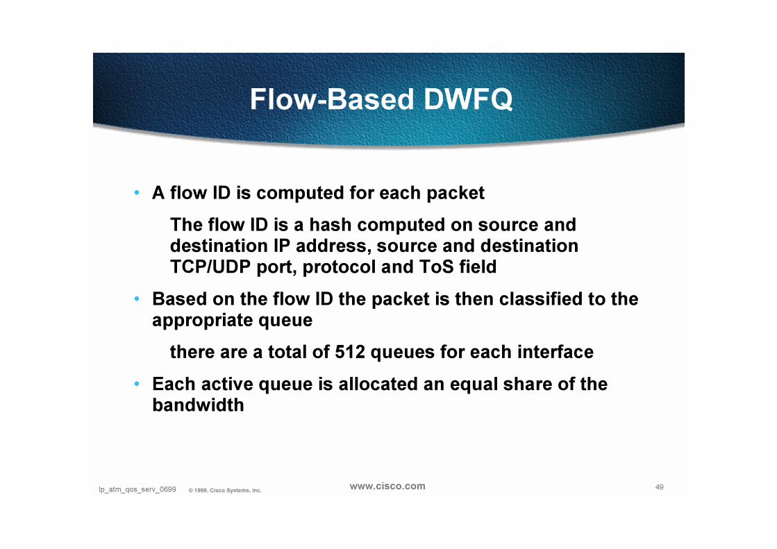
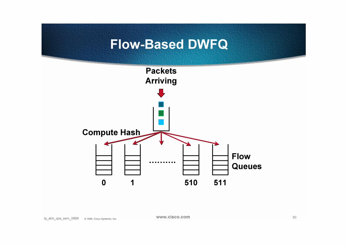
Flow-Based DWFQ
• A flow ID is computed for each packet
The flow ID is a hash computed on source and destination IP address, source and destination TCP/UDP port, protocol and ToS field
• Based on the flow ID the packet is then classified to the appropriate queue
there are a total of 512 queues for each interface
• Each active queue is allocated an equal share of the bandwidth
50Ip_atm_qos_serv_0699 © 1999, Cisco Systems, Inc. www.cisco.com
Flow-Based DWFQ
PacketsArriving
……….
Compute Hash
Flow Queues
0 1 510 511

51Ip_atm_qos_serv_0699 © 1999, Cisco Systems, Inc. www.cisco.com
ToS-Based DWFQ
• Packets are classified into 4 queues based on IP precedence
Follows directly from the precedence value
but MSB of Precedence ignored for queue selection, used as “in/out” bit
• Each queue is weighted
Expressed in percentage (%)
• The weight determines the amount of bandwidth that each active queue is allowed to consume during periods of congestion

52Ip_atm_qos_serv_0699 © 1999, Cisco Systems, Inc. www.cisco.com
ToS-Based DWFQ
PacketsArriving
ToS-Based
0 1 2 3(0 & 4) (1 & 5) (2 & 6) (3 & 7)

53Ip_atm_qos_serv_0699 © 1999, Cisco Systems, Inc. www.cisco.com
QoS-Group-Based DWFQ
• Packets are classified into different queues based on their QoS group
QoS group is set using CAR or QoS policy progation via BGP
• Each queue is weighted
Expressed in percentage (%)
• The weight determines the amount of bandwidth that each active queue is allowed to consume during periods of congestion

54Ip_atm_qos_serv_0699 © 1999, Cisco Systems, Inc. www.cisco.com
QoS-Group-Based WFQ
PacketsArriving
………. Class-Based
0 1 89 99

55Ip_atm_qos_serv_0699 © 1999, Cisco Systems, Inc. www.cisco.com
DWFQ queue size parameters
• The user has the option to set
aggregate queue depth
individual queue depth
• During periods of congestion the individual queue depth limit is enforced
• With ToS and QoS group-based WFQ the user also has the option to set the queue depth for each ToS or QoS group queues
56Ip_atm_qos_serv_0699 © 1999, Cisco Systems, Inc. www.cisco.com
Combination of WFQ / WRED Combination of WFQ / WRED
• Both mechanisms can work together and in conjunction
• Guaranteed delay for real time applications (UDP/RTP, H.323)
• Differentiation on drop probability and drop threshold for bursty data traffic (WWW, FTP, SMTP…)

57Ip_atm_qos_serv_0699 © 1999, Cisco Systems, Inc. www.cisco.com
RSVPRSVP
Reserve 1
Mbps BW
on this line
• Allows users of multimedia apps to reserve network resources and guarantee end-to-end quality of service
• Controlled from router configuration and host applications that implement RSVP
• Enables coexistence of multimedia applications (real-time) with sporadic applications
• Supports both unicast and multicast flows
Reserve 1
Mbps BW
on this line
I need 1 Mbps
BW and 200
msec delay
This app needs
1 Mbps BW and
200 msec delay
58Ip_atm_qos_serv_0699 © 1999, Cisco Systems, Inc. www.cisco.com
“Integrated Service” model Scaling RSVP
• See IETF “RSVP Applicability Statement”
• RSVP not scalable to large Internet networks
• Requirement for Vendor specific aggregation schemes :
Intserv-Diffserv integration

59Ip_atm_qos_serv_0699 © 1999, Cisco Systems, Inc. www.cisco.com
IntServ-DiffServ IntegrationIntServ-DiffServ Integration
RSVP RSVP
QoSClassifier
Premium
Standard
• Egress router
RSVP protocol sent on to destination• Backbone routers
WFQ and/or WRED applied on CoS
• Ingress router
RSVP protocol
Mapped to QoS level (DS)
Forwarded to egress
DS

60Ip_atm_qos_serv_0699 © 1999, Cisco Systems, Inc. www.cisco.com
Link Efficiency
Low Speed WAN QoS ToolsLink Efficiency
Low Speed WAN QoS Tools
• Fragmentation and Interleave (LFI)
• RTP Header Compression (CRTP)

61Ip_atm_qos_serv_0699 © 1999, Cisco Systems, Inc. www.cisco.com
Fragmentation and InterleaveOnly needed on slow links
Elastic Traffic MTUReal-Time MTU
Elastic MTU Real-Time MTUElastic MTU Elastic MTU
214ms Serialization Delay
for 1500 byte Frame at 56 kbps
Mechanisms
Pt to Pt Links - MLPPP with Fragmentation and Interleave
Frame Relay - FRF.12 (Voice and Data can use Single PVC)
ATM - (Voice and Data need separate VC’s on Slow Links)
Before
After
62Ip_atm_qos_serv_0699 © 1999, Cisco Systems, Inc. www.cisco.com
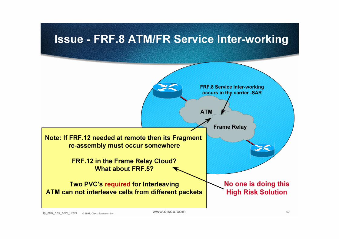
Issue - FRF.8 ATM/FR Service Inter-working
FRF.8 Service Inter-working
occurs in the carrier -SAR
Frame Relay
ATM
Note: If FRF.12 needed at remote then its Fragment
re-assembly must occur somewhere
FRF.12 in the Frame Relay Cloud?
What about FRF.5?
Two PVC’s required for Interleaving
ATM can not interleave cells from different packets
No one is doing thisNo one is doing this
High Risk SolutionHigh Risk Solution
63Ip_atm_qos_serv_0699 © 1999, Cisco Systems, Inc. www.cisco.com
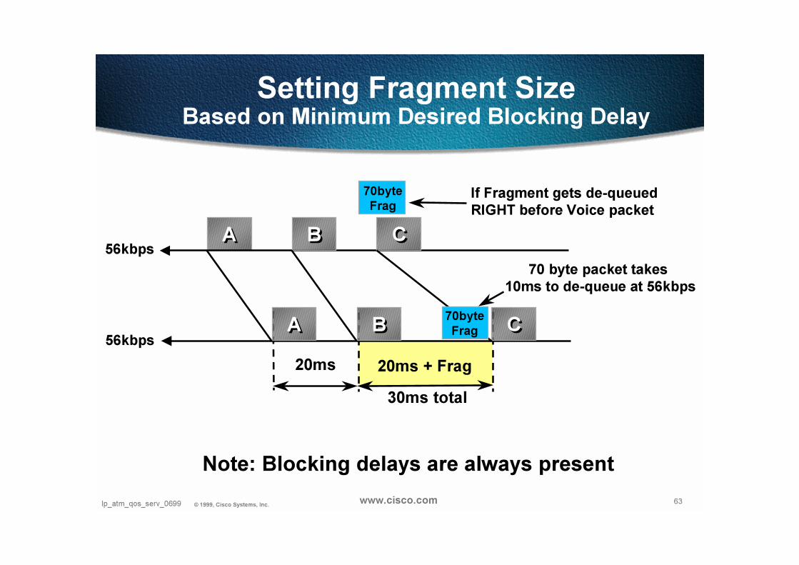
Setting Fragment Size Based on Minimum Desired Blocking Delay
AA BB CC
AA BB CC
70byte
FragIf Fragment gets de-queued
RIGHT before Voice packet
20ms 20ms + Frag
70byte
Frag
56kbps
56kbps
30ms total
Note: Blocking delays are always present
70 byte packet takes
10ms to de-queue at 56kbps

64Ip_atm_qos_serv_0699 © 1999, Cisco Systems, Inc. www.cisco.com
When is Fragmentation Needed?
Frame Size
Depends on the Queuing delay caused by large frames at a givenspeed - Fragmentation generally not needed above 768kbps
56kbps
Link
Speed
143us 9ms 18ms 36ms 72ms 144ms 214ms
1
Byte
64Bytes
128Bytes
256Bytes
512
Bytes
1024
Bytes1500
Bytes
64kbps 125us 8ms 16ms 32ms 64ms 128ms 187ms
128kbps 62.5us 4ms 8ms 16ms 32ms 64ms 93ms
256kbps 31us 2ms 4ms 8ms 16ms 32ms 46ms
512kbps 15.5us 1ms 2ms 4ms 8ms 16ms 23ms
768kbps 10us 640us 1.28ms 2.56ms 5.12ms 10.24ms 15ms
1536kbs 5us 320us 640us 1.28ms 2.56ms 5.12ms 7.5ms
65Ip_atm_qos_serv_0699 © 1999, Cisco Systems, Inc. www.cisco.com
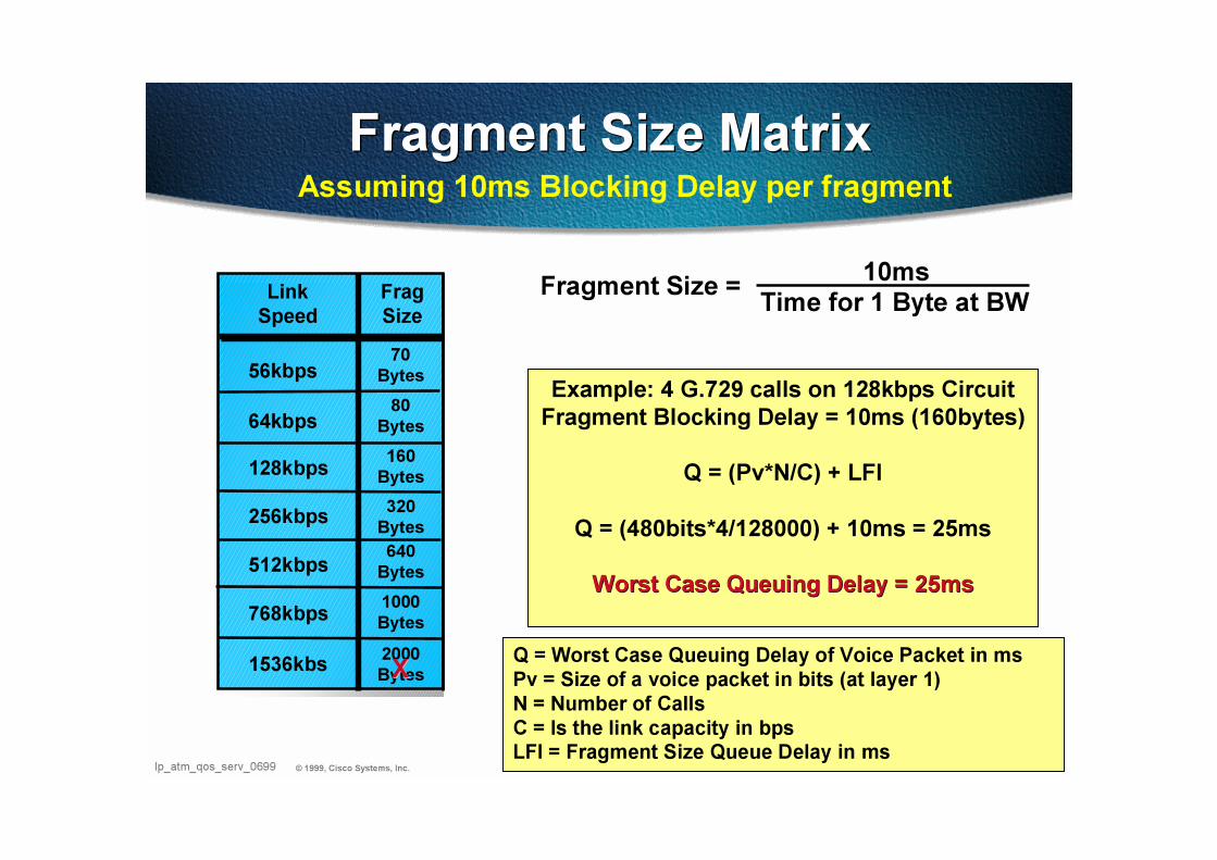
Fragment Size MatrixFragment Size Matrix
Fragment Size =
56kbps70
Bytes
Frag
Size
64kbps80
Bytes
128kbps160
Bytes
256kbps
512kbps
768kbps
1536kbs
320
Bytes
640
Bytes
1000
Bytes
2000
BytesXX
Link
Speed
Assuming 10ms Blocking Delay per fragment
10msTime for 1 Byte at BW
Example: 4 G.729 calls on 128kbps Circuit
Fragment Blocking Delay = 10ms (160bytes)
Q = (Pv*N/C) + LFI
Q = (480bits*4/128000) + 10ms = 25ms
Worst Case Queuing Delay = 25msWorst Case Queuing Delay = 25ms
Q = Worst Case Queuing Delay of Voice Packet in ms
Pv = Size of a voice packet in bits (at layer 1)
N = Number of Calls
C = Is the link capacity in bpsLFI = Fragment Size Queue Delay in ms
66Ip_atm_qos_serv_0699 © 1999, Cisco Systems, Inc. www.cisco.com
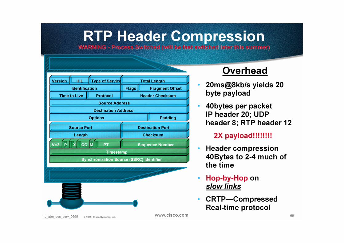
RTP Header CompressionWARNING WARNING -- Process Switched (will be fast switched later this summer)Process Switched (will be fast switched later this summer)
• 20ms@8kb/s yields 20 byte payload
• 40bytes per packet IP header 20; UDP header 8; RTP header 12
2X payload!!!!!!!!2X payload!!!!!!!!
• Header compression 40Bytes to 2-4 much of the time
•• HopHop--byby--HopHop on slow links
• CRTP—Compressed Real-time protocol
OverheadVersion IHL Type of Service Total Length
Identification Flags Fragment Offset
Header ChecksumProtocolTime to Live
Source Address
Destination Address
PaddingOptions
Source Port Destination Port
ChecksumLength
PTMCCXPV=2 Sequence Number
Timestamp
Synchronization Source (SSRC) Identifier

67Ip_atm_qos_serv_0699 © 1999, Cisco Systems, Inc. www.cisco.com
Remote SitesT1
Central
Site
Frame Relay, ATM
128kbps
256kbps
512kbps
768kbps
T1
•Central to Remote Site Speed Mismatch - Avoid
•Remote to Central Site Over-subscription - Avoid
•Prohibit bursting Voice above committed rateWhat are you guaranteed above you committed rate?
Traffic Shaping
Why + What to Avoid?
Traffic Shaping
Why + What to Avoid?
Result:
Buffering = Delay or Dropped Packets

68Ip_atm_qos_serv_0699 © 1999, Cisco Systems, Inc. www.cisco.com
Understanding Shaping ParametersFrame Relay
Traffic Shaping“AVERAGE” Traffic Rate out of an Interface
Challenge - Traffic Still clocked out at line rate
CIR (Committed Information Rate)Average Rate over Time, Typically in bits per second
Bc (Committed Burst)Amount allowed to Transmit in an Interval, in bits
IntervalEqual Integer of time within 1 sec, Typically in ms. Number of Intervals per second
depends on Interval length Bc and the Interval are derivatives of each other
IntervalCIR
Bc125ms
64kbps 8000bits
= =
Be (Excess Burst)Amount allowed to transmit above Bc per Interval
Example
69Ip_atm_qos_serv_0699 © 1999, Cisco Systems, Inc. www.cisco.com
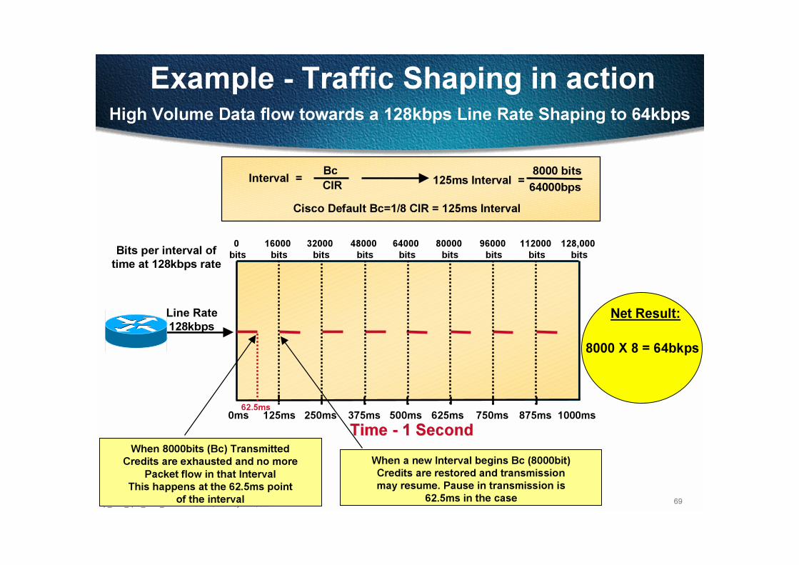
Example - Traffic Shaping in action
0ms 125ms 250ms 375ms 500ms 625ms 750ms 875ms 1000ms
125ms Interval = 8000 bits
64000bps
High Volume Data flow towards a 128kbps Line Rate Shaping to 64kbps
Net Result:Line Rate
128kbps
Interval = Bc
CIR
Bits per interval of
time at 128kbps rate
128,000
bits
0
bits
16000
bits
32000
bits
48000
bits
64000
bits
80000
bits
96000
bits
112000
bits
8000 X 8 = 64bkps
When 8000bits (Bc) Transmitted
Credits are exhausted and no more
Packet flow in that Interval
This happens at the 62.5ms point
of the interval
When a new Interval begins Bc (8000bit)
Credits are restored and transmission
may resume. Pause in transmission is
62.5ms in the case
62.5ms
Time Time -- 1 Second1 Second
Cisco Default Bc=1/8 CIR = 125ms Interval

70Ip_atm_qos_serv_0699 © 1999, Cisco Systems, Inc. www.cisco.com
Bc setting Considerations for VoIP
0ms 125msTime
Set Bc lower if Line rate to CIR ratio is high
Example: T1 Line rate shaping to 64kbps
Traffic Flow
125ms
Interval
0
bits
193000
bits
At T1 rate 8000 bits (Bc)
are exhausted in 5ms. Halting
traffic flow for that PVC
for the rest of that interval.
Even for Voice!
120ms of potential delay
for voice until new interval
begins and Bc credits are
restored
5ms5ms
0ms 15msTime
Traffic Flow
Bits per increment
of time at 128kbps
0
bits
23000
bits
At T1 rate 1000 bits (Bc)
still are exhausted in 5ms.
Halting traffic flow for that PVC
for the rest of that interval.
Even for Voice!
10ms of potential delay
for voice until new interval
begins and Bc credits are
restored
5ms5ms
125ms Interval = 8000 Bc
64kbps CIR
T1 can transmit 193,000 bits in 125ms
Bc = 8000
15ms Interval = 1000 Bc
64kbps CIR
T1 can transmit 23,000 bits in 15ms
Bc = 1000
120ms 10ms
15ms
Interval
71Ip_atm_qos_serv_0699 © 1999, Cisco Systems, Inc. www.cisco.com
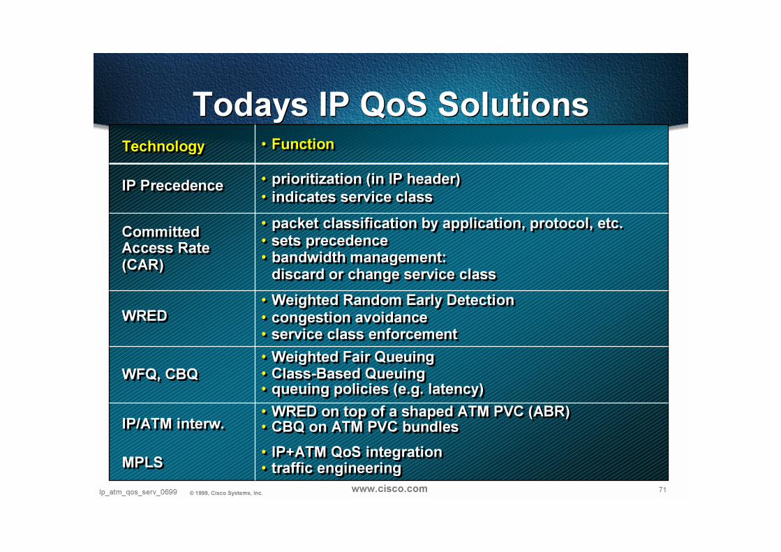
Todays IP QoS SolutionsTodays IP QoS SolutionsTechnology
IP Precedence
CommittedAccess Rate(CAR)
WRED
WFQ, CBQ
IP/ATM interw.
MPLS
Technology
IP Precedence
CommittedAccess Rate(CAR)
WRED
WFQ, CBQ
IP/ATM interw.
MPLS
• Function
• prioritization (in IP header)
• indicates service class
• packet classification by application, protocol, etc.• sets precedence• bandwidth management:
discard or change service class
• Weighted Random Early Detection• congestion avoidance• service class enforcement
• Weighted Fair Queuing• Class-Based Queuing• queuing policies (e.g. latency)
• WRED on top of a shaped ATM PVC (ABR)• CBQ on ATM PVC bundles
• IP+ATM QoS integration• traffic engineering
72Presentation_ID © 1999, Cisco Systems, Inc. www.cisco.com

73Presentation_ID © 1999, Cisco Systems, Inc. 73Presentation_ID © 1999, Cisco Systems, Inc. www.cisco.com
CoS with IP ATM Overlay
CoS with IP ATM Overlay

74Ip_atm_qos_serv_0699 © 1999, Cisco Systems, Inc. www.cisco.com
IP CoS over ATM (Phase 1)
• Multiple Classes of Service reside on the same ABR VC
• Requires a single (ABR) VC for each destination
• Packets (cells) of any class can reside on the same VC
• WRED is run on each VC queue to ensure low loss for higher class service when feedback (RM cells) indicates congestion
VC1
VC2
PerPer--VC WREDVC WRED

75Ip_atm_qos_serv_0699 © 1999, Cisco Systems, Inc. www.cisco.com
Per-VC WRED :Intelligent IP Packet Discard
Per-VC WRED :Intelligent IP Packet Discard
Per-VC
Queues
PerPer--VCVC
QueuesQueues
VIP2-50 PA-A3-XX
Per-VC
WRED:
Intelligent Discard
PerPer--VCVC
WRED:WRED:
Intelligent DiscardIntelligent Discard
Threshold ExceededTraffic
Shaping
Traffic Traffic
ShapingShaping
VC1
VC2
VC3
No discard
on PA
No discardNo discard
on PAon PA
76Ip_atm_qos_serv_0699 © 1999, Cisco Systems, Inc. www.cisco.com
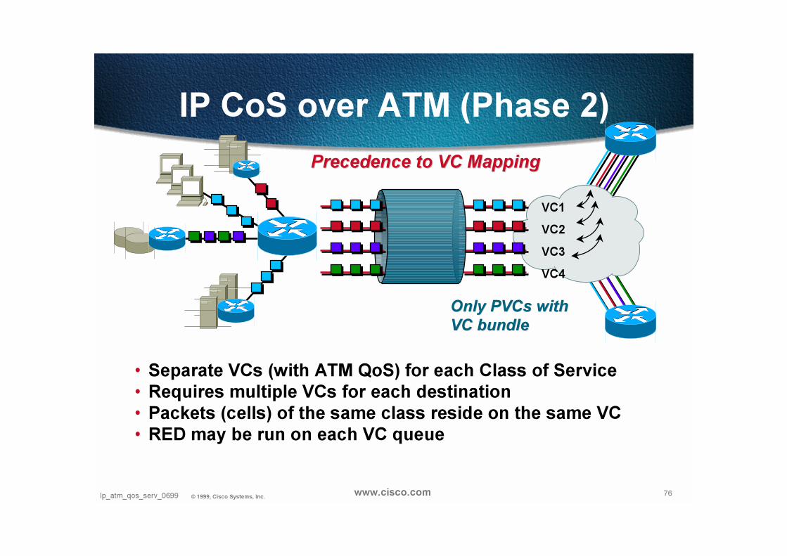
IP CoS over ATM (Phase 2)
• Separate VCs (with ATM QoS) for each Class of Service
• Requires multiple VCs for each destination
• Packets (cells) of the same class reside on the same VC
• RED may be run on each VC queue
VC1
VC2
VC3
VC4
PrecedencePrecedence to VCto VC MappingMapping
Only PVCs with Only PVCs with
VC VC bundlebundle
77Presentation_ID © 1999, Cisco Systems, Inc. 77Presentation_ID © 1999, Cisco Systems, Inc. www.cisco.com
CoS withIP ATM Peer Model
MPLS / Tag
CoS withIP ATM Peer Model
MPLS / Tag
78Ip_atm_qos_serv_0699 © 1999, Cisco Systems, Inc. www.cisco.com
MPLS allows efficient Resource Allocation and COS support
• Taking the example of Cisco Tag Switching:
Tag Classes of Service has key advantage in terms of Resource allocation (over any Overlay model like MPOA)
thanks to allocation at the Class level instead of connection level
Tag Classes of Service allows use of IP-friendly/optimal scheduling mechanisms in ATM switches
WEPD + dynamic buffer control
79Ip_atm_qos_serv_0699 © 1999, Cisco Systems, Inc. www.cisco.com
TAG/MPLS DiffServ ModelTAG/MPLS DiffServ Model
• In non-ATM MPLS, DS bits are mapped into TAG CoS bits (3 bits)
queuing/scheduling and intelligent discard algorithms (WFQ, WRED)
• In ATM-MPLS, LDP associates a CoS to a VC
MPLS-ATM nodes are performing
per class queuing/scheduling (WFQ) and
intelligent discard (WEPD)
80Ip_atm_qos_serv_0699 © 1999, Cisco Systems, Inc. www.cisco.com
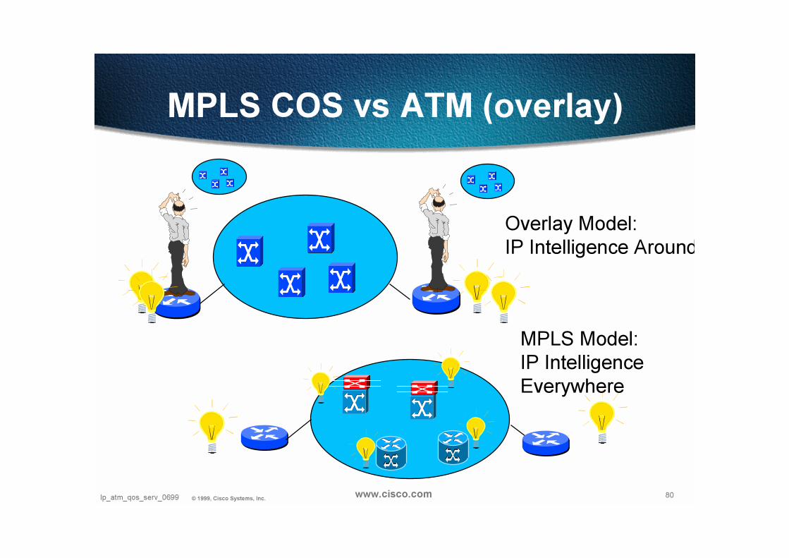
MPLS COS vs ATM (overlay)
Overlay Model:
IP Intelligence Around
MPLS Model:
IP Intelligence
Everywhere
81Presentation_ID © 1999, Cisco Systems, Inc. 81Presentation_ID © 1999, Cisco Systems, Inc. www.cisco.com
Differentiated Servicesvs.
Integrated Services
Differentiated Servicesvs.
Integrated Services

82Ip_atm_qos_serv_0699 © 1999, Cisco Systems, Inc. www.cisco.com
DIFFSERV Working Group CharterDIFFSERV Working Group Charter
There is a clear need for relatively simple and coarse methods of
providing differentiated classes of service for Internet traffic, to support
various types of applications, and specific business requirements.
….
A small bit-pattern in each packet, in the IPv4 TOS octet or the IPv6
Traffic Class octet, is used to mark a packet to receive a particular
forwarding treatment, or per-hop behaviour, at each network node.
A common understanding about the use and interpretation of this bit-
pattern is required for inter-domain use, multi-vendor interoperability, and
consistent reasoning about expected service behaviours in a network.
Thus, the Working Group will standardise a common layout to be
used for both octets, called the 'DS byte'. A standards-track
document will be produced that will define the general use of fields
within the DS byte (superseding the IPv4 TOS octet definitions of
RFC 1349)

83Ip_atm_qos_serv_0699 © 1999, Cisco Systems, Inc. www.cisco.com
The Diffserv Model
IP QoS Edge FunctionsIP QoS Edge Functions
• IP Packet classification
•Traffic classification and DS byte settingbased on multiple criteria
•application
•address source/destination
•Measured bandwidth or burst
• Policing
•control that received traffic conforms to contract CoS of received traffic
Core/Backbone FunctionsCore/Backbone Functions
• High-speed switching
• Per Class Queuing/scheduling
•WFQ
• Per Class intelligent discard
•WRED, WEPD
Edge
Backbone
CPE
AccessDistribution
Core

84Ip_atm_qos_serv_0699 © 1999, Cisco Systems, Inc. www.cisco.com
“Differentiated Service” Model
“Differentiated Service” Model
• Each Packet is coloured with the class it belongs to (DS colouring)
•• IP “IP “DiffservDiffserv” Working Group at IETF” Working Group at IETF , has reshuffled the IPv4 TOS and IPv6 Traffic Classes
into a 6 bits of common DS byte value -DSCP
• Today 3 “precedence” bits (IPv4TOS) allow 7 classes
• Treat the classes differently in the network elements according to “Per Hop Behaviour” values
85Ip_atm_qos_serv_0699 © 1999, Cisco Systems, Inc. www.cisco.com
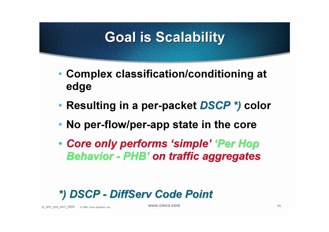
• Complex classification/conditioning at edge
• Resulting in a per-packet DSCP *)DSCP *) color
• No per-flow/per-app state in the core
•• Core only performs ‘simple’ Core only performs ‘simple’ ‘Per Hop ‘Per Hop
BehaviorBehavior -- PHB’PHB’ on traffic aggregateson traffic aggregates
*) DSCP *) DSCP -- DiffServ DiffServ Code PointCode Point
Goal is ScalabilityGoal is Scalability

86Ip_atm_qos_serv_0699 © 1999, Cisco Systems, Inc. www.cisco.com
• Wide variety of services and provisioning policies
• decouple service and application in use
• no application modification
• no hop-by-hop signaling
• interoperability with non-DS-compliant nodes
• incremental deployment
Additional RequirementsAdditional Requirements

87Ip_atm_qos_serv_0699 © 1999, Cisco Systems, Inc. www.cisco.com
• The service provided to a traffic aggregate
• The conditioning functions and per-hopbehaviors used to realize services
• The DS field value (DS codepoint) used to mark packets to select a per-hop behavior
• The particular node implementation mechanisms which realize a per-hop behavior
And a joker!And a joker!
Provisioning Provisioning
4 Kings4 Kings

88Ip_atm_qos_serv_0699 © 1999, Cisco Systems, Inc. www.cisco.com
• QoS does not create bandwidth!
zero-sum game
give better service to a well-provisioned class
with respect to other classes
Why Provisioning?Why Provisioning?

89Presentation_ID © 1999, Cisco Systems, Inc. www.cisco.com
90Presentation_ID © 1999, Cisco Systems, Inc. 90Presentation_ID © 1999, Cisco Systems, Inc. www.cisco.com
DiffServTerminology
DiffServTerminology

91Ip_atm_qos_serv_0699 © 1999, Cisco Systems, Inc. www.cisco.com
• DS Field
the IPv4 header TOS octet or the IPv6 Traffic Class octet
when interpreted in conformance with the definition given in [DSFIELD]
The bits of the DSCP field encode the DS CodePoint
while the remaining bits are currently unused.
• DS CodePoint
a specific value of the DSCP portion of the DS field
used to select a PHB
DSCP field: 6bits Unused: 2bits
Former ToS byte = new DS field
Packet TerminologyPacket Terminology
92Ip_atm_qos_serv_0699 © 1999, Cisco Systems, Inc. www.cisco.com
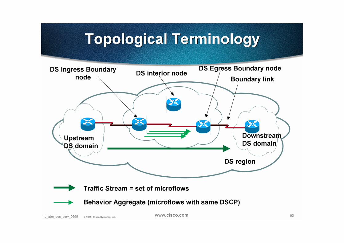
Boundary link
DS Egress Boundary node
Downstream
DS domain
Traffic Stream = set of microflows
DS Ingress Boundary
nodeDS interior node
DS region
Upstream
DS domain
Behavior Aggregate (microflows with same DSCP)
Topological TerminologyTopological Terminology

93Ip_atm_qos_serv_0699 © 1999, Cisco Systems, Inc. www.cisco.com
• Microflow
a single instance of an application-to- application flow of packets
identified by source address, source port, destination address,destination port and protocol id.
• Traffic stream
an administratively significant set of one or more microflows which traverse a path segment.
A traffic stream may consist of the set of active microflows which are selected by a particular classifier.
• Traffic profile
a description of the temporal properties of a traffic stream such as rate and burst size.
• DS Behavior Aggregate = Behavior Aggregate (BA)
a collection of packets with the same DS CodePoint crossing a link in a particular direction.
Traffic TerminologyTraffic Terminology
94Ip_atm_qos_serv_0699 © 1999, Cisco Systems, Inc. www.cisco.com
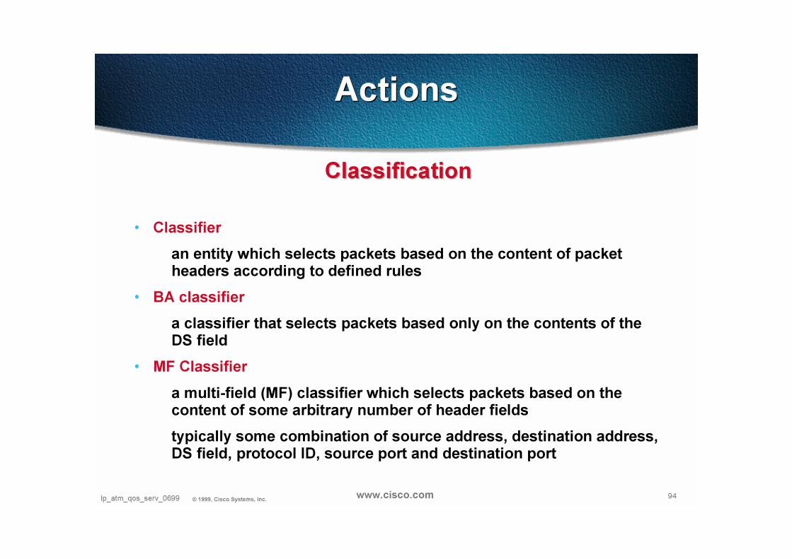
ClassificationClassification
• Classifier
an entity which selects packets based on the content of packet headers according to defined rules
• BA classifier
a classifier that selects packets based only on the contents of the DS field
• MF Classifier
a multi-field (MF) classifier which selects packets based on the content of some arbitrary number of header fields
typically some combination of source address, destination address, DS field, protocol ID, source port and destination port
ActionsActions
95Ip_atm_qos_serv_0699 © 1999, Cisco Systems, Inc. www.cisco.com
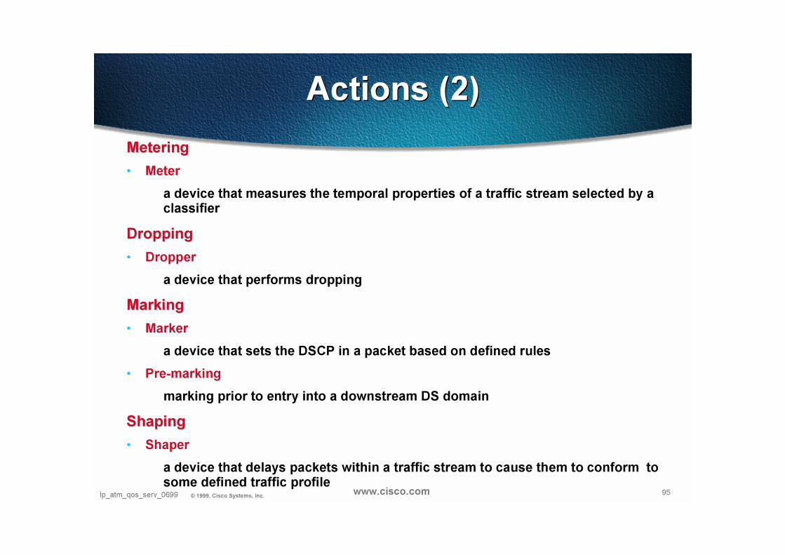
MeteringMetering
• Meter
a device that measures the temporal properties of a traffic stream selected by a classifier
DroppingDropping
• Dropper
a device that performs dropping
MarkingMarking
• Marker
a device that sets the DSCP in a packet based on defined rules
• Pre-marking
marking prior to entry into a downstream DS domain
ShapingShaping
• Shaper
a device that delays packets within a traffic stream to cause them to conform to some defined traffic profile
Actions (2)Actions (2)

96Ip_atm_qos_serv_0699 © 1999, Cisco Systems, Inc. www.cisco.com
PolicingPolicing
• Policer = Dropper
a device that discards packets (dropper) within a traffic stream in accordance with the state of a corresponding meter enforcing a traffic profile
Traffic ConditioningTraffic Conditioning
• Traffic Conditioner
an entity that may contain meters, markers, droppers and shapers
Typically deployed in boundary DS nodes only
A traffic conditioner may re-mark a traffic stream or may discard or shape packets to alter the temporal characteristics of the stream and bring it into compliance with a traffic profile
• Traffic Conditioning Agreement (TCA)
an agreement specifying classifier rules and any corresponding traffic profiles and metering, marking, discarding and/or shaping rules which are to apply to the traffic streams selected by the classifier
Actions (3)Actions (3)

97Ip_atm_qos_serv_0699 © 1999, Cisco Systems, Inc. www.cisco.com
• Per-Hop-Behavior (PHB)
the externally observable forwarding behavior applied at a DS-compliant node to a DS behavior aggregate
• PHB group
a set of one or more PHBs that can only be meaningfully specified and implemented simultaneously, due to a common constraint applying to allPHBs in the set such as a queue servicing or queue management policy
a PHB group provides a service building block that allows a set of related forwarding behaviors to be specified together (e.g., four dropping priorities)
a single PHB is a special case of a PHB group
• Mechanism
a specific algorithm or operation (e.g., queueing discipline) that is implemented in a node to realize a set of one or more per- hop behaviors
PHB TerminologyPHB Terminology
98Ip_atm_qos_serv_0699 © 1999, Cisco Systems, Inc. www.cisco.com
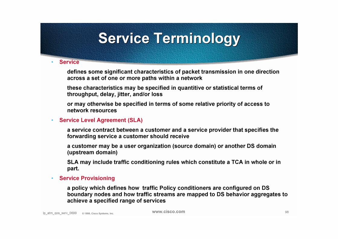
• Service
defines some significant characteristics of packet transmission in one direction across a set of one or more paths within a network
these characteristics may be specified in quantitive or statistical terms of throughput, delay, jitter, and/or loss
or may otherwise be specified in terms of some relative priority of access to network resources
• Service Level Agreement (SLA)
a service contract between a customer and a service provider that specifies the forwarding service a customer should receive
a customer may be a user organization (source domain) or another DS domain (upstream domain)
SLA may include traffic conditioning rules which constitute a TCA in whole or in part.
• Service Provisioning
a policy which defines how traffic Policy conditioners are configured on DS boundary nodes and how traffic streams are mapped to DS behavior aggregates to achieve a specified range of services
Service TerminologyService Terminology

99Ip_atm_qos_serv_0699 © 1999, Cisco Systems, Inc. www.cisco.com
0. Negociation and agreement of an SLA/TCA
SLA/TCA
DiffServ ArchitectureDiffServ Architecture

100Ip_atm_qos_serv_0699 © 1999, Cisco Systems, Inc. www.cisco.com
1. Pre-marking in the source domain
- per-application/host basis
- per-default-gateway basis
DiffServ ArchitectureDiffServ Architecture

101Ip_atm_qos_serv_0699 © 1999, Cisco Systems, Inc. www.cisco.com
2. Egress Boundary DS Node of source domain applies traffic conditioning to ensure SLA/TCA compliance
hence causing possible re-marking, dropping and shaping
SLA/TCA
DiffServ ArchitectureDiffServ Architecture

102Ip_atm_qos_serv_0699 © 1999, Cisco Systems, Inc. www.cisco.com
3. Classification according to SLA
4. Conditioning according to TCA
5. Assignment to a BA (DSCP setting)
SLA/TCA
DiffServ ArchitectureDiffServ Architecture
103Ip_atm_qos_serv_0699 © 1999, Cisco Systems, Inc. www.cisco.com
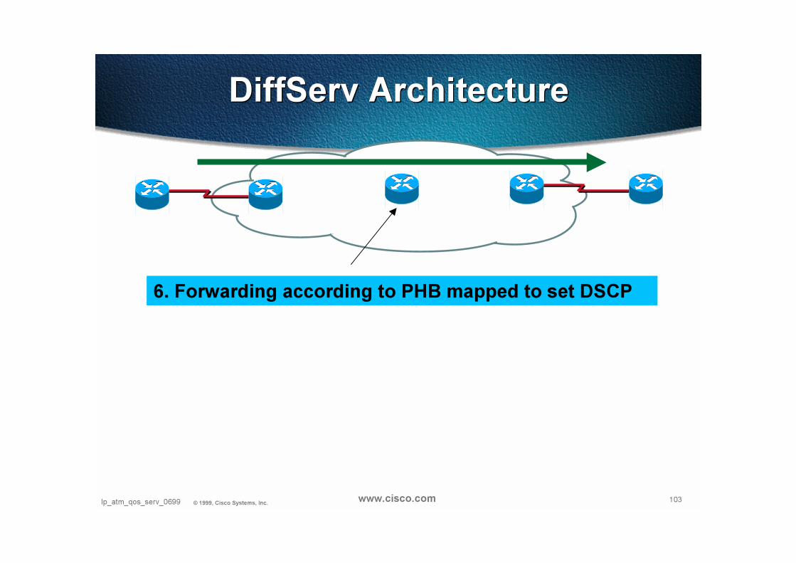
6. Forwarding according to PHB mapped to set DSCP
DiffServ ArchitectureDiffServ Architecture

104Ip_atm_qos_serv_0699 © 1999, Cisco Systems, Inc. www.cisco.com
If downstream DS domain support same service provisioning policy, same PHBs and DSCP/PHB mappings
Then 7: No-op
Else 7’a: SLA’/TCA’ negotiation
7’b: Conditioning according to TCA’
SLA’/TCA’
DiffServ ArchitectureDiffServ Architecture
105Ip_atm_qos_serv_0699 © 1999, Cisco Systems, Inc. www.cisco.com
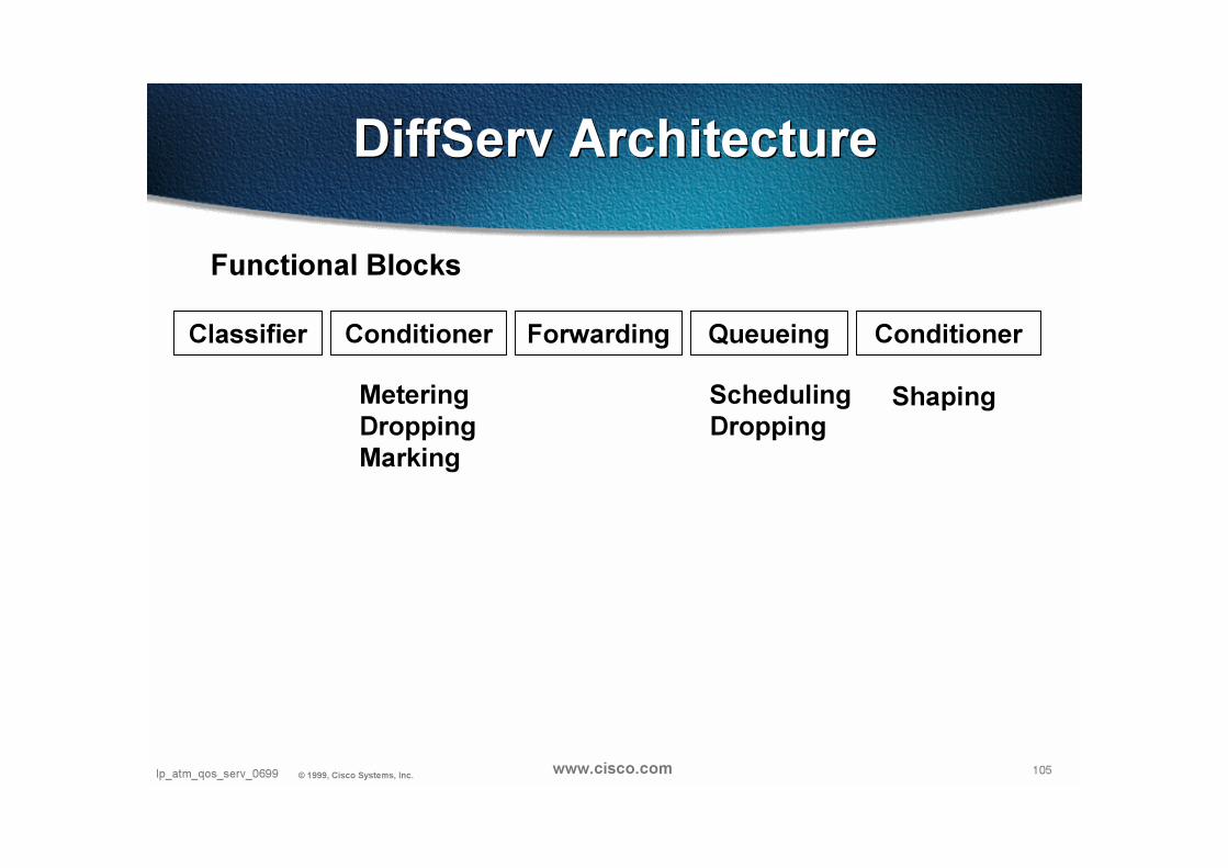
Classifier Conditioner Forwarding Queueing Conditioner
Functional Blocks
MeteringDroppingMarking
ShapingSchedulingDropping
DiffServ ArchitectureDiffServ Architecture

106Ip_atm_qos_serv_0699 © 1999, Cisco Systems, Inc. www.cisco.com
• QPPB
Based on source or destination address
AS-path or community or access-list
Scalable Return direction
Classifier Conditioner Forwarding Queueing Conditioner
MeteringDroppingMarking
DiffServ ArchitectureDiffServ Architecture

107Ip_atm_qos_serv_0699 © 1999, Cisco Systems, Inc. www.cisco.com
• CAR
mac-address
precedence
std/extended ACL
all traffic
Classifier Conditioner Forwarding Queueing Conditioner
MeteringDroppingMarking
DiffServ ArchitectureDiffServ Architecture

108Ip_atm_qos_serv_0699 © 1999, Cisco Systems, Inc. www.cisco.com
Classifier Conditioner Forwarding Queueing Conditioner
• CAR
token bucket metering
commited rate, normal burst (bucket depth), exceed burst (tcp-friendly behavior)
set prec/tx, set prec/cont, set qos/tx,seq qos/cont, drop, tx, cont
MeteringDroppingMarking
DiffServ ArchitectureDiffServ Architecture

109Ip_atm_qos_serv_0699 © 1999, Cisco Systems, Inc. www.cisco.com
Classifier Conditioner Forwarding Queueing Conditioner
• EF
DiffServ ArchitectureDiffServ Architecture

110Ip_atm_qos_serv_0699 © 1999, Cisco Systems, Inc. www.cisco.com
Classifier Conditioner Forwarding Queueing Conditioner
• Scheduling
“Which packet first?”
FIFO, PQ, CQ, WFQ (CB, FB), DWFQ (CB, FB), MDRR
on physical interface
ATM: special case
SchedulingDropping
DiffServ ArchitectureDiffServ Architecture
111Ip_atm_qos_serv_0699 © 1999, Cisco Systems, Inc. www.cisco.com
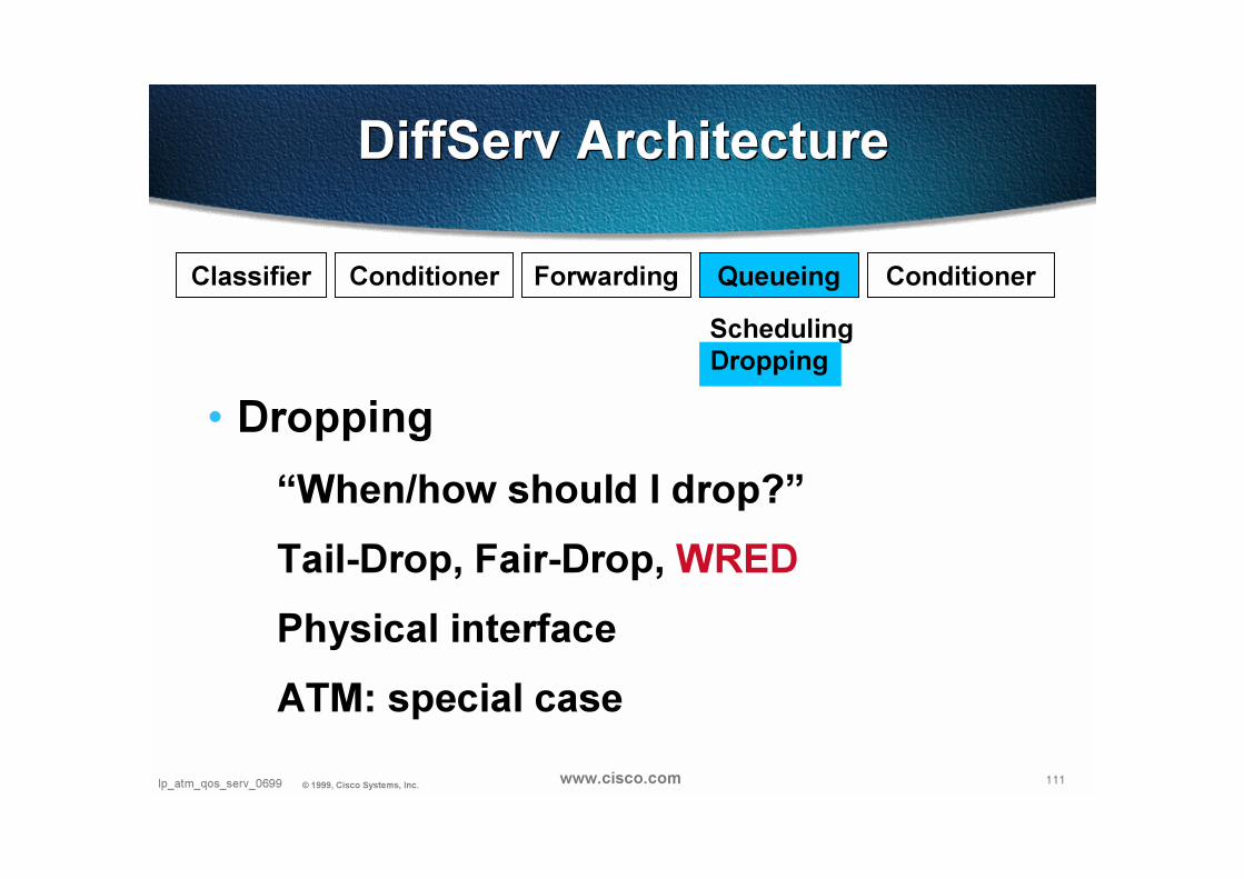
Classifier Conditioner Forwarding Queueing Conditioner
• Dropping
“When/how should I drop?”
Tail-Drop, Fair-Drop, WRED
Physical interface
ATM: special case
SchedulingDropping
DiffServ ArchitectureDiffServ Architecture
112Ip_atm_qos_serv_0699 © 1999, Cisco Systems, Inc. www.cisco.com
Classifier Conditioner Forwarding Queueing Conditioner
• GTS/FRTS
DiffServ ArchitectureDiffServ Architecture
113Ip_atm_qos_serv_0699 © 1999, Cisco Systems, Inc. www.cisco.com
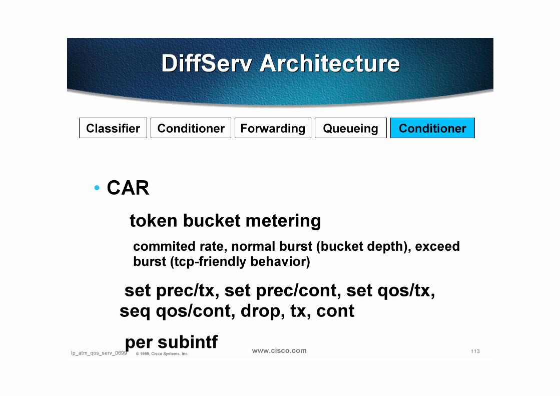
Classifier Conditioner Forwarding Queueing Conditioner
• CAR
token bucket metering
commited rate, normal burst (bucket depth), exceed burst (tcp-friendly behavior)
set prec/tx, set prec/cont, set qos/tx,seq qos/cont, drop, tx, cont
per subintf
DiffServ ArchitectureDiffServ Architecture

114Presentation_ID © 1999, Cisco Systems, Inc. www.cisco.com