quality management in rollform design - ubeco
TRANSCRIPT
Rollform Design Software
Quality Management in Rollform Design Dipl.-Ing. Roland Brandegger, UBECO GmbH Iserlohn , Germany Not only much experience and know-how of the designer are needed, but also a lot of tiresome tedious work has to be done, if cold rolled profiles and roll tools are to be designed. Today the diligence works like calculating and creating drawings are done by special software systems [1], so that the designer can concentrate on his actual task, the design and optimizing of the flower pattern and the geometry of the roll tools. The experience however has to be obtained by time-consuming and expensive trial and error. A new three steps quality management helps. Rollforming is a continuous bending operation in which sheet or strip metal is gradually formed in tandem sets of rollers until the desired cross-sectional configuration is obtained. Exactly this is the problem: if single points of the sheet cross-section are tracked, movements on curves with different lengths are observed. The result is different strain and stress of the material. As long as this occurs within the elastic bounds, strain disappears again after the profile leaves the final stand of the rollforming machine and the desired profile form can be obtained. If however the yield stress is exceeded, remaining strain arises. The local "too much" of material causes unwanted deformations like rippled edges, mostly in case of symmetric profiles. If the profile is non-symmetric, twists around the longitudinal axis or curved profiles can result. When this occurs, time-consuming and expensive modifying of the roll tools is necessary. Step 1: Stress of Band Edge Yet at an early stage research in rollforming concentrated in methods to predict strain and stress during the design
process. A first approach was to describe the band edge curve by a mathematical function [2] and to derive strain and stress from it. The results are displayed by the software PROFIL in a bar diagram. The length of each bar shows the relative stress between two stands related to the yield point of the material. A
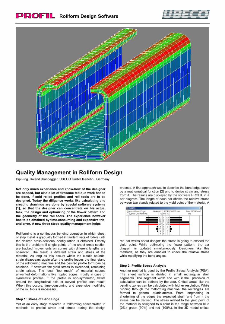
red bar warns about danger: the stress is going to exceed the yield point. While optimizing the flower pattern, the bar diagram is updated simultaneously. Designers like this methods, as they are enabled to check the relative stress while modifying the bend angles. Step 2: Profile Stress Analysis Another method is used by the Profile Stress Analysis (PSA): The sheet surface is divided in small rectangular shell segments. The segment width and with it the precision of calculation can be defined by the user. Critical areas like the bending zones can be calculated with higher resolution. While running through the rollforming machine, the rectangles are formed to general quadrilaterals. From lengthening or shortening of the edges the expected strain and from it the stress can be derived. The stress related to the yield point of the material is assigned to a color in the range between blue (0%), green (50%) and red (100%). In the 3D model critical
Rollform Design Software
areas can be detected by red colored shell segments. The designer can use the mouse wheel to rotate and zoom the model to examine any detail. The profile stress analysis is an integrated feature of the software PROFIL and works without FEA (Finite Element Analysis), this means the results are available after key-stroke immediately.
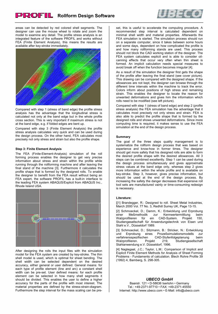
Compared with step 1 (stress of band edge) the profile stress analysis has the advantage that the longitudinal stress is calculated not only at the band edge but in the whole profile cross section. This is very important if maximum stress is not at the band edge, e.g. if folded edges are bent up. Compared with step 3 (Finite Element Analysis) the profile stress analysis calculates very quick and can be used during the design process. On the other hand, FEA calculates most precisely not only stress and strain but also the profile shape. Step 3: Finite Element Analysis The FEA (Finite-Element-Analysis) simulation of the roll forming process enables the designer to get very precise information about stress and strain within the profile while running through the rollforming machine and after leaving the final stand of the machine [3]. Furthermore it calculates the profile shape that is formed by the designed rolls. To enable the designer to benefit from the FEA result without being an FEA expert, the software PROFIL has a built-in interface to the leading FEA system ABAQUS/Explicit from ABAQUS Inc., Rhode Island USA.
After designing the rolls the input files with the simulation model for the FEA system are created by key-stroke. The thin shell model is used, which is optimal for sheet bending. The shell width can be selected dependent on the desired accuracy, either general or user defined. General means: for each type of profile element (line and arc) a constant shell width can be pre-set. User defined means: for each profile element can be selected in how many shell segments it should be divided. This enables the user to define a higher accuracy for the parts of the profile with most interest. The material properties are defined by the stress-strain-diagram. Furthermore the step interval for the mass scaling can be pre-
set, this is useful to accelerate the computing procedure. A recommended step interval is calculated dependent on minimal shell width and material properties. Afterwards the FEA simulation is started. The simulation process should run on a separate computer, since it takes between some hours and some days, dependent on how complicated the profile is and how many rollforming stands are used. This process should not block the CAD working station of the designer. The FEA system calculates explicit and is able to consider oil-canning effects that occur very often when thin sheet is formed. An implicit calculation needs special measures to avoid break off when the function becomes irregular [4]. As a result of the simulation the designer first gets the shape of the profile after leaving the final stand (see cover picture). This drawing can be compared with the designed shape. If the allowances are not kept, the designer can browse through the different time intervals within the machine to track the error. Colors inform about positions of high stress and remaining strain. This enables the designer to locate the reason for unwanted deformations and gives him the information which rolls need to be modified (see left picture). Compared with step 1 (stress of band edge) and step 2 (profile stress analysis) the FEA simulation has the advantage that it calculates most precisely not only stress and strain. FEA is also able to predict the profile shape that is formed by the designed rolls and shows unwanted deformations. Since more computing time is required, it makes sense to use the FEA simulation at the end of the design process. Summary The goal of the three steps quality management is to systematize the rollform design process that was based on experience and know-how in former times. The designer should get more safety that his designed rolls are able to form the desired profile shape with the desired allowances. All 3 steps can be combined excellently. Step 1 can be used during the design process simultaneously and gives approximate stress values at the band edge only, whereas step 2 gives more information within the whole profile and is available on key-stroke. Step 3, however, gives precise information, but should be used at the end of the design process. By increasing the safety the danger decreases that expensive roll tool sets are manufactured vainly or time-consuming redesign is necessary. Literature: [[1] Brandegger, R.: Designed to roll. Sheet Metal Industries, March 2000 Vol. 77 No. 3, Redhill Surrey UK, Page 13-15. [2] Schmoeckel, D.; Damm, K.: Entwicklung und Erprobung einer Meßmethodik zur Kennwertermittlung beim Walzprofilieren für ein CAD-System. Projekt 150, Studiengesellschaft für Anwendungstechnik von Eisen und Stahl e.V., Düsseldorf 1989. [3] Schmoeckel, D.; Sitzmann, B.: Stricker, N.: Entwicklung und Erprobung eines Prozeßsimulationsmodells zur verfahrensspezifischen CAD-Stufenfolgeplanung beim Walzprofilieren. Projekt 219, Studiengesellschaft Stahlanwendung e.V. Düsseldorf, 1996. [4] Nagtegaal, J.C.; Taylor, L.M.: Comparison of Implicit and Explicit Finite Element Methods for Analysis of Sheet Forming Problems - Fundaments of calculation. Blech Rohre Profile 39 (1992) 4, Bamberg, S. 298-305.
UBECO GmbH Baarstr. 121 • D-58636 Iserlohn • Germany
Tel.: +49-2371-97710 • FAX: +49-2371-45550 Internet: http://www.ubeco.com • E-Mail: [email protected]