quality evaluations of the fuel bundle welds and
TRANSCRIPT
3 A - 1IIIIIIIIHI
CA9800557
QUALITY EVALUATIONS OF THE FUEL BUNDLE WELDSAND BRAZED JOINTS BY ACOUSTIC MICROSCOPY
M. SOARE, C. IORDACHE, R. CIOCAN, V. REVENCO, V. DRAGNEUltraacoustics R & D Laboratory
I. POPESCU, R. MOSCALUNuclear Fuel Performance Group
RENEL-INSTITUTE FOR NUCLEAR RESEARCHPitesti-ROMANIA
ABSTRACTFor more than 20 years, the quality control of the end-cap, end-plates welds and of the
brazed appendage joints is made by destructive methods (metallographic examinations ormechanical tests) on specimens sampled from production.
Having a very limited statistics, these destructive methods are useful only to indicate"trends" of the production quality, not for detecting infrequent single defect events.
It is recognized that nondestructive examination techniques are required to achievesufficient evidence of the production quality, at a statistically significant sampling rate.
For this reason, the INR-Ultraacoustics R&D Lab has develop a family of equipmentsfor high resolution ultrasonic imaging, at performances close to the Acoustic Microscopydomain.
The paper make a presentation of the examination methods and of the experimentalresults obtained on characteristic welds and brazed joints samples. Detailed oif-line evaluationsof the C-scan and B-scan ultrasonic images are made and comparative analyses withmetallography are performed. Also, in the case of end-cap welds, numerical stress analysis aremade, in order to establish the influence of flaws on the weld strength.
1. INTRODUCTION
The nuclear fuel bundles of CANDU type consist of a number of zircaloy-4 clad fuelelements spot-welded, at each end, to an end plate (figure 1).
Main mechanisms of in-reactor defects of the fuel bundles are related especially to thefuel elements closure welds (end-cap welds) and end-plate welds. These are: opening-up ofincomplete welds and fatigue growth of the cracks initiated in the weld heat-affected zone
In order to reduce the in-reactor failure probability, it is necessary to have a minimumnumber of defects in the final manufacturing stage.

3A-2
For this, it is recognized that nondestructive examination methods are required toachieve sufficient "visibility" of the production quality, at a statistically significant samplingrate [12].
Ultrasonic examination is of a particular interest because it allow the volumetriccharacterization of the structural integrity of the welded and brazed zones, inclusively HAZ;high resolutions can be obtained with the new high-frequency imaging techniques [10].
On the other hand, being a relatively high-speed nondestructive method .the ultrasonicexamination can be applied for a statistically significant quality evaluation.
2. MICROSTRUCTURE CHARACTERIZATION OF THE FUEL BUNDLEWELDS
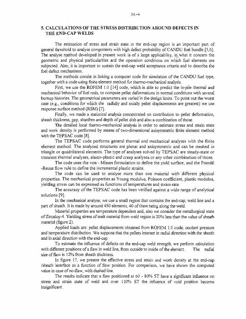
Being electric resistance welds, the end-cap and the end-plate welds are essentiallysolid-state bonding with a sandwich-like macrostructure [3], There are three distinct zonesaround the welded regions (figure 2, for the case of the end-cap weld [13]):
a) base metal (zone 1, equiaxed grains);b) recristallized zone (zone 2, slightly elongated grains parallel with the weld-line),c) dynamically recristallized zone (zone 3, fine-grained, containing persistent limits
due to precipitation of the alloying elements, especially Sn).These zones have not only different microstructure, but also they have different
mechanical and acousto-elastic properties [2]. However, they have sufficient high ultrasonictransparence and lower microstructure noise for a good signal to noise ratio, even to 50MHz.
3. EXAMINATION METHOD AND EQUIPMENTS
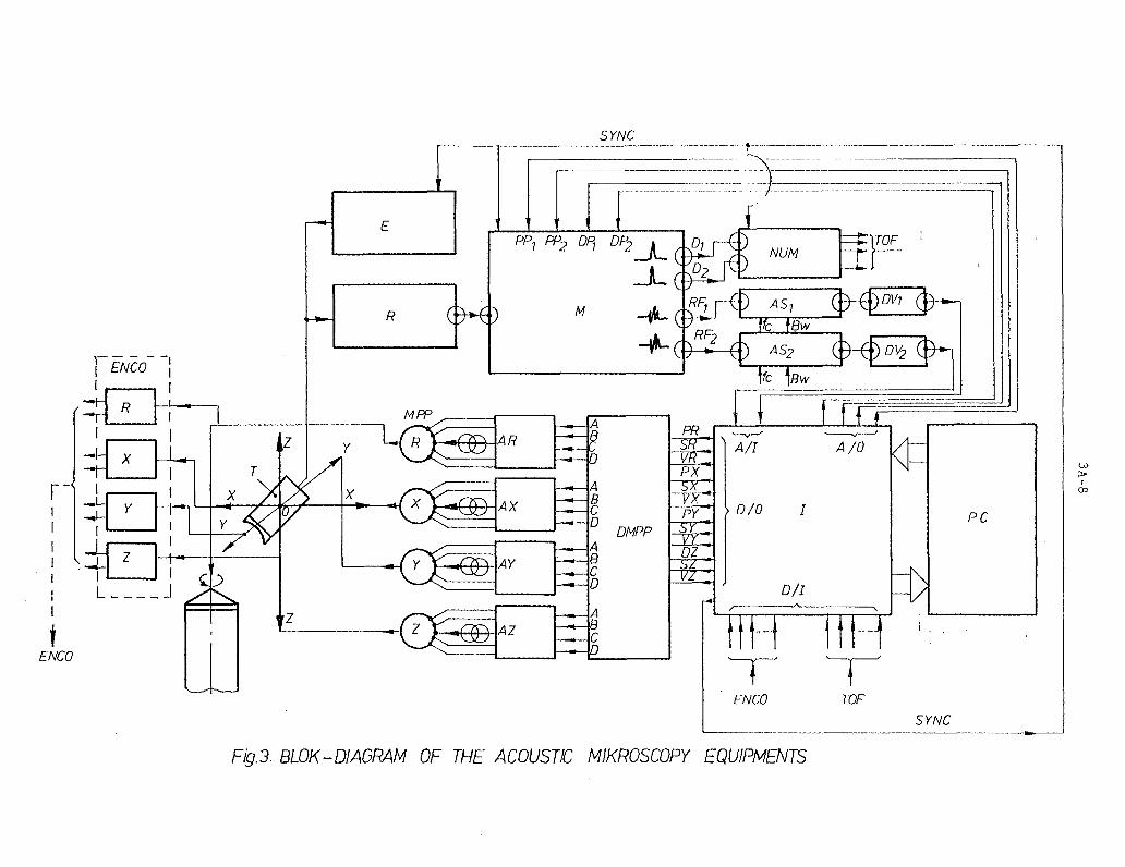
The nondestructive examination of the fuel bundle welds and brazed joints is based onthe automatic scanning of the weld and brazed zones with a very high focused ultrasonicbeam. To perform this, high resolution computer controlled mechanical scanning devices weredeveloped. Synchronous with the scanning of the investigated spatial domain, automaticacquisition of the ultrasonic amplitude and time-of-flight data are performed. In this way,ultrasonic C-Scan and B-Scan images of the welds volume are obtained [1],
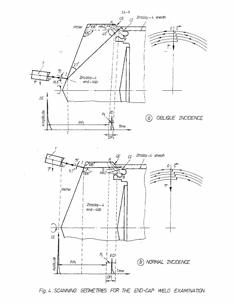
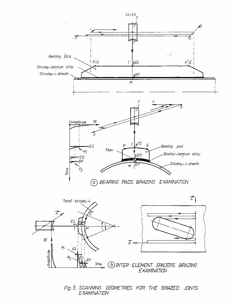
The examination is made in immersion, using high-frequency/high-damped transducers,with beam incidence on the cap surface (fig.4), for the end-cap welds, on the external platesurface in the case of the end-plates welds (fig.6), and on the bearing pad or inter-eiementspacer surface (fig.5) in the case of brazed joints examination.
The block-diagram of the MICROSCAN equipments for Acoustic Microscopyinvestigations by C-scan and B-scan methods, is presented in fig.3.
For obtaining a good in-depth resolution, the ultrasonic signals are broad-bandamplified with a bandwidth close to the frequency response range of the transducer.
For obtaining a good lateral resolution, the flaw signal are separately amplified in anarrow-band tuned on a frequency selected in the high-frequency region of the spectralresponse of the transducer.
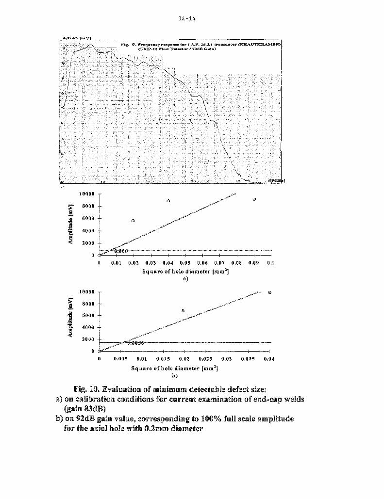
In figure 9, it is shown the frequency response of a high-resolution transducer, used inour investigations (IAP-FM 25.3.1/KRAUTKRAMER).

3A-3
For this transducer, which are 0.3mm beam diameter, the minimum size of thedetectable flaw was determined by extrapolation of the amplitude response obtained for axialholes with different diameter values (<t>i=0.14mm, <J>2=0-2mm, and <t>3=0.3mm, fig.8). Theresults are presented in figure 10, for two different cases:
a) At 8SdB gain (the current value for end-cap examination). In this case, the noise islower than the. 8% amplitude threshold of the USIP12 flaw detector, and."the correspondingminimum size of the detectable defect is around 80um diameter.
b) At 92dB gain, which correspond to 100% full scale amplitude of the axial hole with^-O. lmm diameter. In this case, the maximum noise level is 14% of the amplitude scale, andthe corresponding minimum size of the detectable defect is around 75um diameter. This is aphysical limit of the system, for the specified transducer. It is important to note that, becauseof the complex welds geometry, both position and width of the flaw gates are variable duringthe scanning process.
4. EXPERIMENTAL RESULTS
End-cap welds examinationThree types of flaws are typical for the end-cap examination, as it results from our
investigations:(1) Incomplete welds along the weld line (fig. 13, right).(2) Inclusions in the HAZ (fig. 13, left).(3) Cracks at the reentrant corner (fig.l 1 and 12).
The incomplete welds is the most common defect type and it is also provided and currentlyevaluated by the metallographical procedures. The inclusion-type flaw and the flaws in thereentrant corner zone are not usually the object of metalographic examination procedures.
However, these type of flaws are very significant for the structural integrity of the end-cap weld, as it is discussed in the reference [4] and is, also, demonstrated by our calculationsof stress distributions (chapter 5).
End-plate welds examinationsThe most frequent type of flaw encountered in our investigations are 2-dimensional
border defects, associated with transversal aria reduction of the weld zone. Some times, inthese distorted welds, isolated internal flaw are present, as it can be seen in fig. 15.
Generally, the welds from the external circle of the plate-end are symmetric and with aminimum of 3.5mm in diameter (fig. 14). The defect welds are most often present on theinternal circles of the plate-end.
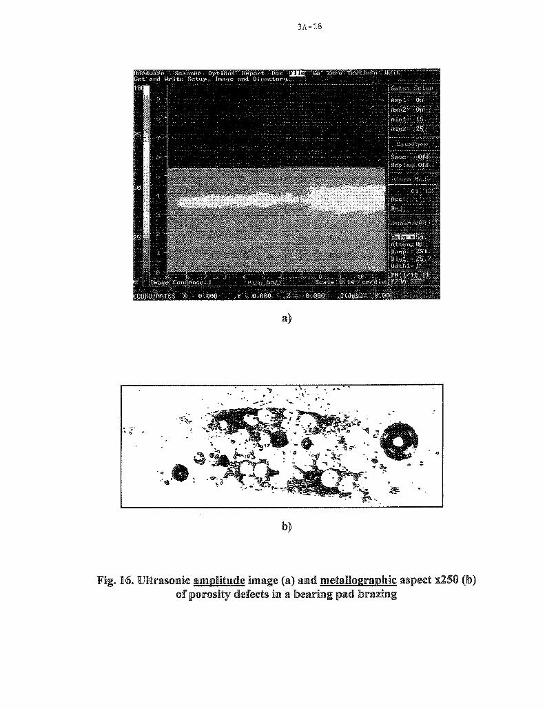
Brazed jointsPorosity in the brazing zirconium beryllium alloy are the most common defect (fig. 16).Frequently, porosity is associated with high thickness of the brazing layer. If the
distance between the isolated pores are lower than the wavelength, the ultrasonic echo signalis of multipole type.
3A-4
5. CALCULATIONS OF THE STRESS DISTRIBUTION AROUND DEFECTS INTHE END-CAP WELDS
The estimation of stress and strain state in the end-cap region is an important part ofgeneral threshold to analyse components with high defect probability of CANDU fuel bundle [5,6].The analyse method developed in present work is of a large applicability, inwhat it concern thegeometric and physical particularities and the operation conditions on which fuel elements aresubjected. Also, it is important to sustain the end-cap weld acceptance criteria and to describe thefuel defect mechanisms.
The methods consist in linking a computer code for simulation of the CANDU fuel type,together with a code using finite element method for thermo-mechanical analysis.
First, we use the ROFEM 1.0 [14] code, which is able to predict the in-pile thermal andmechanical behavior of fuel rods, to compute pellet deformations in normal conditions with severalburnup histories. The geometrical parameters are varied in the design limits. To point out the worstcase (e.g., conditions for which the radially and axially pellet displacements are greatest) we useresponse surface method (RSM) [7].
Finally, we made a statistical analysis concentrated on contribution to pellet deformation,sheath thickness, gap, shanfren and depth of pellet dish and also a combination of those.
The detailed local thermo-mechanical analysis in order to estimate stress and strain stateand work density is performed by means of two-dimensional axisymmetric finite element methodwith the TEPSAC code [8].
The TEPSAC code performs general thermal and mechanical analyses with the finiteelement method. The analysed structures are planar and axisymmetric and can be meshed intriangle or quadrilateral elements. The type of analyses solved by TEPSAC are steady-state ortransient thermal analyses, elasto-plastic and creep analyses or any other combination of those.
The code uses the von - Misses formulation to define the yield surface, and the Prandtl-Reuss flow rule to define the incremental plastic strains.
The code can be used to analyse more than one material with different physicalproperties. The mechanical properties as Young modulus, Poisson coefficient, plastic modulus,yielding stress can be expressed as functions of temperatures and strain rate.
The accuracy of the TEPSAC code has been verified against a wide range of analyticalsolutions [9].
In the mechanical analyse, we use a small region that contains the end-cap, weld line and apart of sheath. It is made by around 450 elements, 40 of them being along the weld.
Material properties are temperature dependent and, aiso we consider the metallurgical stateof Zircaloy-4. Yielding stress of melt material from weld region is 20% less than the value of sheathmaterial (figure 2).
Applied loads are: pellet displacements obtained from ROFEM 1.0 code, coolant pressureand temperature distribution. We suppose that the pellets interact in radial direction with the sheathand in axial direction with the end-cap.
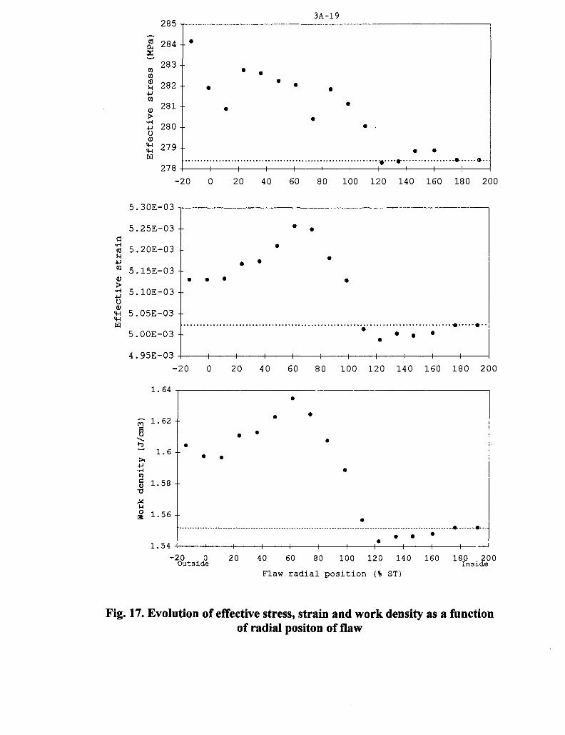
To estimate the influence of defects on the end-cap weld strength, we perform calculationwith different positions of a flaw in weld line, from outside to inside of the element. The radialsize of flaw is 12% from sheath thickness.
In figure 17, we present the effective stress and strain and work density at the end-cap/sheath interface as a function of flaw position. For comparison, we have shown the computedvalue in case of no-flaw, with dashed line.
The results indicate that a flaw positioned at 60 - 80% ST have a significant influence onstress and strain state of weld and over 110% ST the influence of void position becomeinsignificant.
3A-5
6. CONCLUSIONS
The nondestructive examination of the CANDU fuel bundle welds_a"nd brazed joints ispossible by high-frequency ultrasonic techniques.
The INR-Ultraacoustics R&D Laboratory has developed the MICROSCAN-02equipment for ultrasonic examination of the end-plates welds and brazed joints and theMICROSCAN-03 equipment for ultrasonic examination of the end-cap welds. The depth andlateral resolution of these equipments are close to the Acoustic Microscopy domain.
In fact, an effective resolution of 0.05mm can be obtained for x50 magnification factor.Thus, the ultrasonic C-Scan and B-Scan images can shown microstructure details at a scalecomparable with the usual metallography.
On the other hand, the ultrasonic method has the advantage to be a high-speednondestructive method which provide a volumetric characterization of structural integrity ofwelds and brazed joints.
Powerful calculus methods are developed for analysis of the stress and straindistribution around the flaws.
ACKNOWLEDGMENTS
The authors wish to gratefully acknowledges to the INR Managing Director, Mr.S.Valeca and to the Scientific Director, Mr. C.Gheorghiu for theirs constant help,encouragement and understanding.
REFERENCES
1. M. SOARE, R. CIOCAN, V. REVENCOMETHODS FOR ULTRASONIC EXAMINATION OF CANDU FUEL BUNDLEWELDS AND BRAZED JOINTS(INR - IR no.4146/1993 - in romanian).
2. M. SOARE, C. IORDACHE, V. REVENCO, V. DRAGNEEQUIPMENT AND PROCEDURE FOR NONDESTRUCTIVE EXAMINATIONOF THE CANDU FUEL END-CAP WELDS.(INR - IR No.4518/1994 - in romanian).
3. P.B.NAGY, L.ADLERULTRASONIC EVALUATION OF SOLID-STATE BONDS(Materials Evaluation/November 1992)
4. M. TAYAL et al.ELASTIC-PLASTIC STRESS DISTRIBUTION NEAR THE END-CAP OF A FUELELEMENT (AECL - 10646/1992).
5. R. SEJNOHAetal.PERFORMANCE OF END-CAP WELDS IN 37-ELEMENT CANDU FUEL(Proc. Second Int. Conf. on CANDU Fuel, Chalk River, Canada, 1989)

3A-6
6. G. HORHOIANU, D.R. MOSCALU, I.A. POPESCUSTRESS ANALYSIS IN THE END-CAP WELD REGION OF PHWR CANDUTYPE FUEL ELEMENTS(Annual Meting on Nuclear Technology 1995, Nurnberg, Germany)
7. D.R. MOSCALU et al.CANDU TYPE FUEL BEHAVIOR EVALUATION - A ^PROBABILISTICAPPROACH(4 th International Conference on CANDU Fuel, 1995, Canada)
8. T.R. HSUTHE FINITE ELEMENT METHOD IN THERMOMECHANICS(Allen & Unwin, Boston, 1986)
9. I.A. POPESCU et al.ANALYSIS OF CHANGES IN THE END-CAP/SHEATH WELD STRENGTH INTHE PRESENCE OF MANUFACTURE WELD LINE DEFECTS(INR-IR No.4146/1993 - in romanian)
10. N.M. CALSONetal.ULTRASONIC NDT METHODS FOR WELD SENSING(Materials Evaluation/November 1992)
11. R. SEJNOHA, L. MAGNOLIASSURING THE COMPLETENESS OF CLOSURE WELDS IN CIRENE FUELELEMENTS
12. J. VAN DEN ANDELULTRASONIC INSPECTION OF END-CAP WELDS IN THIN WALLED FUELELEMENTS(Materials Evaluation/February 1977)
13. V. PITIGO1 et al.DETERMINATION OF LOCAL YIELD LIMITS IN THE END-CAP WELDREGION OF THE CANDU FUEL(INR-IR No.4146/1993 - in romanian)
14. D.R. MOSCALU et al.VALIDATION OF INR CODES DESTINED TO THE BEHAVIOR ANALYSIS OFCANDU TYPE NUCLEAR FUEL(INR-IR No.4381/1994 - in romanian)
3A-7
1. ZIRCALOY BEARING PADS2. ZIRCALOY FUEL SHEATH3. ZIRCALOY SUPPORT PLATE4. URANIUM DIOXIDE PELLETS5. INTER ELEMENT SPACERS6. END CAPS
Fig. 1. CANDU 37 nuclear fuel bundle
Sheath2.5
Fig. 2. The local properties zones around a typical end-cap weld
SYNC
. BLOK-DIACRAM OF THE ACOUSTIC MIKROSCOPY EQUIPMENTS
Water
3A-9
Q£ Zjrcaloy-lt sheathAS / /
© OBLIQUE INCIDENCE
Z'rcaloy-C sheafh
L
b) NORMAL INCIDENCE
Fig. t. SCANNING GEOMETRES FOR THE END-CAP WELD EXAMINAVON
-X
Bearing pad
Zircatay-b&jtium alloy
Zircaioy-U sheath .
3A-10T
M
Bearing pad
Zi'rcaloy-benlium alloy
Zircaby- L sheath
@ BEARING PADS BRAZING EXAMINATION
Teacc zircaloy-i
b) INTER-ELEMENT SFACERS BRAZINGEXAMINATION
Fig. 5- SCANNING GEOMETRIES FOR THE BRAZED JOINTSEXAMINATION.

3A-11
Fuel element
\End-plate
End-cap
\
X
\
1
\
Bearing pads
4 H N.
\
End-cap Zircaloy- 4 sheath
End-plate / / • /
\
7 ES
1 1 1i 1 1
Time
7
Fig. 6 SCANNING GEOMETRY FOR THE END PLATEWELDS EXAMINATION

3A-12
n100
Fig. 7.Ultrasonic amplitude(A) and time-of-flight(Z) Images of the reference samplesfor calibration at normal incidence (left) and oblique incidence (right) in the case of
PARAMETERS
Sample Code : DTNCI (four radial holes of 0.5mm diameter)
Transducer : IAP.FM 253.1 / KRAUTKRAMERGain : 38 dBDetection
Threshold: 20%Scanned Zone : 0--3607CircumferentiaI Resolution = 0.07mm
0-1.2mm/Radial Resolution = 0.05mm
DTIC1 (four holes of 0.5mm diameter,inclined to 45° in the radial-axial plane)IAP.FM 253.1 / KRAUTKRAMER§8dB
20%0~3607Circumferential Resolution = 0.07mm2--4.4mm/Radial Resolution = 0.05mm

3A-13
Sample:
hole of 0.3mm diameter) Sample: BTS-3(asial hole of 0.4mm
Fig. 8. Ultrasonic amplitude images of the minimum defect size reference samples
PARAMETERS
Transducer : IAP.FM 25.3.1 / KRABTKRAMERGaira : 63 dBDetection Threshold : 20%Scammed Zone : Rectangular 2x2mm2 / Resolutiom = 0.005mm
3A-14
A/O.42 fmVl
Fig. 9. Frequency response for I.A.P. 25.3.1 transducer (KRAUTKRAMEK)(USIP-12 Flaw Detector / 70dB Gain)
f[MHi)
I10000 -r
8000
17 6000
S. 4000 +I< 2000
0 <£ -+- H-0 0.01 0.02 0.03 0.04 0.05 0.06 0.07 O.OS 0.09 0.1
Square of hole diameter [mm2]a)
0.005 0.01 0.015 0.02 0.025 0.03 0.035 0.04
Square of hole diameter [mm2]b)
Fig. 10. Evaluation of minimum detectable defect size:a) on calibration conditions for current examination off end-cap welds

3A-15
amplitude image for sample BT18 at normal incidence,zone it cam be seen the image of the reentrant corner flaw
from fig. 12.PARAMETERS
Sample CodeTransducerGainDefectionScanned Zone
: IAP.FM 2S.3.1 / KRAUTKRAMER:§3dB: 20%: 0—3607CircumfementiaI Resolution = iO—lmm/Radial Resolution = 0.025mm
Fig. 12, Metallograpfaic aspect (s5®0) of aw reentrant corner crack.

3A-16
a, b, c, d are artificial flaws
xlOO
Sample: ESN Sample: DOP1
Ultrasonic amplitude images and metallographic aspects for an inclusionflaw in the HAZ (left) and for weld line type flaws (right).
PARAMETERS
: IAP.FM 25.3.1 / KRAUTKRAMER:83dB
Detection T5sreslio8d: 20%Scamraed Zone °. 0~3607Circumferential Resolution = 0,
2-2.4mm/Radia! ResolutioH = 0.05mm

3A-17
Fig. 14. UltrasoEic amplitude image of a welded end-plate.
Fig. IS. Ultrasonic amplitude image of the defect weld encircled ira fig. 14.
3A-18
Fig, 16. Ultrasonic amplitude image (a) and metallograipfaie aspect s250 (b)sit
285 T-3A-19
278-20 0 20 40 60 80 100 120 140 160 180 200
C•H<0
uW
-H4Jo(1)1-1<wtx)
5.25E-03 -
5.20E-03 -
5.15E-03 -
5.10E-03 -
5.05E-03 -
5.00E-03 -
4.95E-03 -
. . .
1 1 1 1 1 1 1 1 1 1
-20
1.64
20 40 60 80 100 120 140 160 180 200
1.54-20 0
Outside 40 60 80
Flaw r a d i a l p o s i t i o n (% ST)
100 120 140 160 180 200Inside
Fig. 17. Evolution of effective stress, strain and work density as a functionof radial positon of flaw