qualifying fiber for 10g deployment - amazon web …€¦ · · 2017-05-03qualifying fiber for...
TRANSCRIPT

© 2017, Slide 1 of 25
Qualifying Fiber for
10G Deployment
Presented by:
Bob Chomycz, P.Eng. Email: [email protected]
Tel: 1.888.250.1562
www.TelecomEngineering.com

Slide 2 of 25 © 2017 r0
Telecom Engineering
Introduction Offices in USA and Canada
In the past 18 years we have engineered/ installed/tested; > 400 fiber network nodes such as SONET, DWDM, CWDM, routers, switches, etc.
onto >40,000 km of fiber
created 7000 network documentation drawings
building networks globally
Products: WDM LiteTM brand passive multiplexers, CWDM, DWDM, Cross Band, Bi-directional, EDFA
Optical amplifiers, dispersion compensation, test equipment
Resellers of MRV Communications products
Services: Engineering, installation, provisioning, testing and documentation
24x7 network monitoring and expert technical support services
On staff experienced network design and installation engineers
Customers / clients: telcos, carriers, utilities, ISPs, other network service providers
Many references available

Slide 3 of 25 © 2017 r0
Why do we need to Qualify
Fiber to 10G? Due to the high data rate and very short pulse width, fiber parameters have a greater affect at 10G communications than at lower speeds. Fiber is qualified for 10G operation at a specific fiber length.
Parameters to Consider: optical power loss, fiber, connectors, splices, other (Power Meter/OTDR)
optical return loss, reflections in fiber (ORL)
chromatic dispersion (CD)
polarization mode dispersion (PMD)
optical signal to noise ratio (OSNR)*
non linear effects*
First 4 parameters are measured during “Fiber Characterization” type field measurement.

Slide 4 of 25 © 2017 r0
Span Loss • Typical good quality fiber attenuation is 0.25 dB/km @1550nm
• Typical 10G transceivers optical budget is 23 dB @1550nm
• Resulting maximum span fiber length 92 km if no other losses present (23dB / 0.25dB/km).
• Need to include 3 dB power penalty at 10G for CD and PMD
• Therefor, maximum optical budget is 20 dB and fiber distance is 80km (20dB / 0.25dB/km), 50 miles.
• However, typical 10G transceiver is also limited to 80km by fiber’s chromatic dispersion*.
• Distance can possibly be exceeded by using optical amplifiers and dispersion compensation
*Note: values indicated in this presentation assume standard single mode fiber is being used, type ITU G.652

Slide 5 of 25 © 2017 r0
Span Loss
Span loss should be measured with a calibrated power meter and light source at the wavelengths used for communications.
– Typical non WDM, 1310nm and 1550nm
– For DWDM systems, 1550nm measurement is usually adequate
– For CWDM systems, measurement should be made over each channel using a CWDM laser test source or CWDM transceiver.
Be careful to record span loss to at least 1 decimal place.
Be sure fiber connectors are clean, use a fiber scope if necessary to visually check for cleanliness.
Be careful not to overpower the optical receiver. Typical overload level is -7dBm and damage threshold is 0 dBm.

Slide 6 of 25 © 2017 r0
Span Loss

Slide 7 of 25 © 2017 r0
Span Loss
Slide 8 of 25 © 2017 r0
Optical Time Domain Reflectometer
(OTDR)
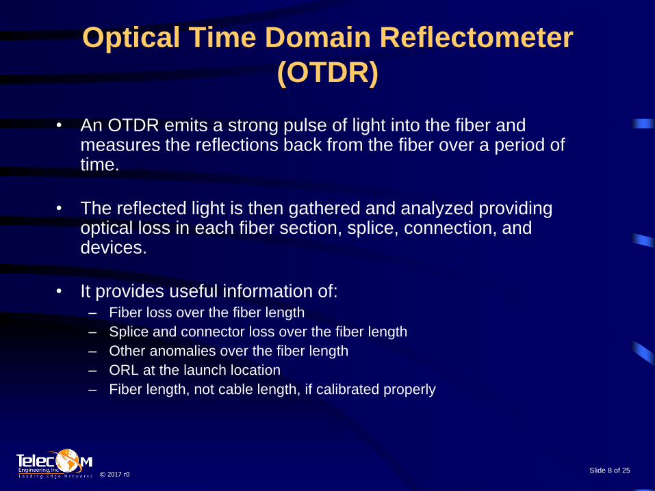
• An OTDR emits a strong pulse of light into the fiber and measures the reflections back from the fiber over a period of time.
• The reflected light is then gathered and analyzed providing optical loss in each fiber section, splice, connection, and devices.
• It provides useful information of: – Fiber loss over the fiber length
– Splice and connector loss over the fiber length
– Other anomalies over the fiber length
– ORL at the launch location
– Fiber length, not cable length, if calibrated properly

Slide 9 of 25 © 2017 r0
Optical Time Domain Reflectometer
(OTDR)

Slide 10 of 25 © 2017 r0
Optical Return Loss (ORL)
• ORL is the measure of the total reflected light from connectors,
splices and the fiber that returns to the output Tx port of the
optical transceiver’s (SFP/XFP/etc) transmit laser.
• If the returned light power is strong enough, it can destabilize
the laser, and cause bit errors .
• High ORL measurements are typically due to poor quality and/or
dirty connectors. Use SC-UPC or LC-UPC for 10G
communications.
• ORL is measured with an ORL meter or OTDR. Read
instructions carefully, it is not a simple procedure.
• Many transceivers require typical ORL of 27 dB.

Slide 11 of 25 © 2017 r0
Optical Return Loss (ORL)

Slide 12 of 25 © 2017 r0
Chromatic Dispersion (CD)
• Laser light comprises a spectrum of light wavelengths
• Different wavelengths of laser light propagate down a fiber at slightly different speeds and arrive at the end of the fiber at different times
• This results in, signal pulse spreading

Slide 13 of 25 © 2017 r0
Chromatic Dispersion (CD) • Because of the much smaller pulse width at 10Gbps (100ps)
than 1Gbps, (1ns) Pulse spreading that may not affect 1G significantly can make it difficult for the 10G receiver to distinguish between different pulses in the same fiber length and thereby causing bit errors.
• For standard single mode fiber, non DSF, (ITU G.652, SMF28e) pulse spreads about 16 to 17ps/nm.km at 1550nm. Typical limit for 10G transceiver is ~1400ps/nm or 80km (50 miles). At 1300nm dispersion is ~ 0ps/nm.km.

Slide 14 of 25 © 2017 r0
Chromatic Dispersion (CD)
• To compensate for high chromatic dispersion, dispersion compensation modules (DCM) are used. DCM adds to fiber span loss.
• Typically come marked with the length of fiber the DCM compensates, example 60km or 90km, and what fiber type they compensate.
• Chromatic dispersion can be measured in a fiber span in order to determine amount to compensate for the dispersion effect.

Slide 15 of 25 © 2017 r0
Polarization Mode
Dispersion (PMD) • High PMD results in bit errors and/or outages
• It is caused by different light polarizations in the fiber arriving at the receiver at different times, which results in pulse spreading
• Light propagation delay in different polarizations is due to distortion in fiber symmetry (fiber is not perfectly round). Distortion is caused by imperfect manufacturing techniques and stresses on the fiber cable

Slide 16 of 25 © 2017 r0
PMD
• Older fiber cables may have worst PMD due to less tolerance in manufacturing and longer period of environmental stresses on the cable.
• Only concern for transmission rates of 10 Gbps and higher
• Typically, for 10 Gbps transceivers PMD measured value should be below 8 ps, for 5 nines (99.999%, 5 min/year) channel availability.
• It is generally not possible to compensate for fiber with high PMD.
• It is practically impossible to estimate fiber PMD for older fiber cables in long spans.
• Best is to measure all fibers in cable for PMD and reserve fibers with low PMD for 10 G traffic traffic, all other fibers for 1G and slower speeds.

Slide 17 of 25 © 2017 r0
Optical Signal to Noise
Ratio (OSNR)
• Measure of signal power to noise power ratio
• Only consider if optical amplifiers (EDFA, SOA, Raman) are used to boost 10G signal
• For 10G, typically 24 dB to 28 dB depending on dispersion compensation and PMD

Slide 18 of 25 © 2017 r0
Non Linear Effects
• Signal distortion and interference is created when when too much power is launched into a fiber
• When optical amplifiers are used.
• In general, best to keep launch power under +6 dBm for non DWDM / CWDM transmissions. (dependent on fiber type and transceiver).

Slide 19 of 25 © 2017 r0
“Rule of Thumb” thresholds
for Selected 10G Transceivers
1 Gbps 10 Gbps
Optical
Budget <40 dB <20 dB
CD <170 km* <80 km*
PMD NA 8 ps
ORL 27 dB 27 dB
OSNR 18-22 dB 24-28 dB
BER 10e -12 10e -12 * For ITU G.652 fiber

Slide 20 of 25 © 2017 r0
Optical Amplifiers
Used to extend the reach of 10G transmission.
Compensate for unexpected fiber link losses and loss due to DWDMs and/or DCMs (Dispersion Compensation Modules)
Does not compensate for fiber dispersion, require separate DCM.
Available to extend electric utility relay signaling over long distance fiber. Schweitzer (SEL) and Schneider Electric approved.

Slide 21 of 25 © 2017 r0
Optical Amplifiers EDFA Erbium-Doped Fiber Amplifier technology is used to
amplify C & L bands (1529 to 1625 nm).
Gain available from 3 dB to >27 dB
Output power available from +3 dBm to >+17 dBm
Available as Post (Booster), In-Line, or Pre-Amp
Used for DWDM applications and non DWDM situations where fiber loss is great
Raman Amplifier technology is available to amplify any wavelengths (common from 1529 to 1612 nm). Gain available from 3 dB to ~10 dB, with very little to no noise
introduction
Raman Amplifier is usually placed at the end of a fiber span amplifying light being received (Pre-Amp).
Used to extend EDFA systems that have reached OSNR noise limit.

Slide 22 of 25 © 2017 r0
Our Services
We provide a complete “turn-key” solutions from engineering design to installation and product supply.
We offer our clients:
• Fiber Characterization (we qualify fiber for 10G communication)
• Engineering design, supply, installation and turn-up of fiber optic networks
• Network documentation services
• 24x7 network monitoring and technical support services

Slide 23 of 25 © 2017 r0
Our Products Our Lite TM Brand:
• 4, 8, 16, 32 wavelength passive DWDM, 10G, 100 Gig ready
• 4, 8, 18 wavelength passive CWDM
• DWDM/CWDM M-ROADM, OADM
• Optical Amplifiers
• Dispersion Compensation Modules
• Pluggables, SFP, XFP, GBIC, Xenpak
• FTTH Routers, Switches, CPE
• Fiber optic test equipment
• Software; F-Intermod, BER Calculator
MRV Communications:
• Fiber Driver Transponder Shelf
Wireless Systems:
• Xirrus
• Radwin
Books: - Planning Fiber Optic Networks, Author Bob Chomycz, McGraw-Hill, ISBN 0-07-1499199
- Fiber Optic Installers Field Manual, Author Bob Chomycz, McGraw-Hill

Slide 24 of 25 © 2017 r0
Recommended Reading
Planning Fiber Optic Networks
- Author Bob Chomycz
- ISBN 978-0-07-149919-4
- Available from Amazon.com
Fiber Optic Installer’s Field Manual
- Author Bob Chomycz
- ISBN 978-0-07-181867-7
- Available from Amazon.com
© 2017, Slide 25 of 25
Call Toll Free: 1-888-250-1562
www.TelecomEngineering.com
Presented by:
Bob Chomycz, P. Eng., President
Email: [email protected]