qualification testing of screened category · pdf filequalification testing of screened...
TRANSCRIPT

Independent Testing - For End User Confidence
QUALIFICATION TESTING OFSCREENED CATEGORY 5 (CAT. 5e) CONNECTING HARDWARE +
ACCORDING TO REQUIREMENTS OFPROPOSED CENELEC 2nd EDITION EN 50173,
PROPOSED ISO/IEC 2nd EDITION 11801, AND ANSI/TIA/EIA-568-B.2PRODUCED BY
TELEBOX INDUSTRIES CORPORATION
Screened 24 Port Patch Panel, Category 5 (Cat. 5e), RJ 45+
Telebox Identification LP248SX
Prepared by Jesper B. Hansen
Project No.: 101390 2002.07.19

Page 2 of 39
3P Project No. 101390
TABLE OF CONTENTS PAGE
1. IDENTIFICATION 3
2. SURVEY OVER THE WORK 4
3. APPLIED SPECIFICATIONS 5
4. CONDITIONS OF TESTING 6
4.1 Connecting Hardware Types covered by the Transmission Testing 64.2 Electrical Measurements 6
5. FACTORY INSPECTION 7
5.1 Company Organization 75.2 Quality Assurance 75.3 Production Facilities 95.4 Final Testing 9
6. SUMMARIZED TEST RESULTS 11
6.1 De-Embedded NEXT Values of Applied RJ 45 Plugs 116.2 Return Loss 126.3 Attenuation 136.4 Near End Crosstalk 146.5 Far End Crosstalk 156.6 Input to Output Resistance 166.7 Input to Output Resistance Unbalance 176.8 Current Carrying Capacity 176.9 Propagation Delay 176.10 Delay Skew 186.11 Electromagnetic Performance 186.12 Balance Measured as Transverse Conversion Loss (TCL) 196.14 Transfer Impedance 206.12 Insulation Resistance 206.14 Voltage Proof 20
7. CONCLUSION 21
8. APPENDIX: Data Sheets of Transmission Performance versus Frequency 22
Page 3 of 39
3P Project No. 101390
1. IDENTIFICATION
Project No.: 101390
Subject: Qualification Testing of Screened Category 5 (Cat. 5e) Connecting+
Hardware according to Requirements of Proposed CENELEC 2ndEdition EN 50173, Proposed ISO/IEC 2nd Edition 11801 andANSI/TIA/EIA-B.2
Connecting Hardware: Screened, Category 5 (Cat. 5e), RJ 45, 24 Port Patch Panel+
Manufacture: Telebox Industries Corporation
Telebox Identification: LP248SX
PCB Marking: ECT1 94V-Ø1902 001-0802
Supplier: Telebox Industries Corporation4F, No. 306, Sec 1, Ta-Tung RoadHsi-Chin ChenTaipeiTaiwan, R.O.C.
Prepared by: 3P Third Party TestingAgern Allé 3DK-2970 HoersholmDenmark
Email: [email protected]: + 45 45572200Fax: + 45 45765708Homepage: http://www.3Ptest.dk
Author: Jesper B. Hansen

Page 4 of 39
3P Project No. 101390
2. SURVEY OF THE WORK
3P has performed qualification testing of screened Category 5 (Cat. 5e) 24 Port Patch Panel from+
Telebox, type LP248SX. The connecting hardware has been supplied for the testing at 3P byTelebox in May 2002.
Testing was carried out in May and June, 2002.
Testing has included a verification of performance according to all relevant international standardsand standard proposals. This means that the following specifications stating electrical transmissionrequirements are covered by the present testing:
• ISO/IEC 11801, Cat. 5• CENELEC EN 50173, Cat. 5• ISO/IEC Proposal for 2nd Edition 11801, Cat. 5:2000+• CENELEC Proposal for 2nd Edition EN 50173, Cat. 5:2000+• ANSI/TIA/EIA-568-B.2, Cat. 5e
The transmission performance of the screened Category 5 (Cat. 5e) connecting hardware from+
Telebox, type LP248SX does in every respect comply with all specified requirements.
The company
Telebox Industries Corporation4F, No. 306, Sec 1, Ta-Tung RoadHsi-Chin ChenTaipeiTaiwan, R.O.C.
is qualified at their Hsi-Chih site to produce the connecting hardware in question with a 3P ratingas Screened Category 5 (Cat. 5e) ISO/IEC, EN & TIA/EIA Connecting Hardware.+
The qualification will be valid until failure to pass one of the maintenance test programmes, whichwill be performed at 12 months intervals.
It should be noted that the present testing does not include the reliability test programmesspecified in CENELEC, ISO/IEC, and TIA/EIA standards. Only the transmission performance iscovered by the 3P testing. It is assumed that the contact reliability of the applied RJ 45 jacks isadequate to secure safe interconnection to the patch cords throughout a lifetime of normalapplication of the connecting hardware.

Page 5 of 39
3P Project No. 101390
3. APPLIED SPECIFICATIONS
The transmission performance requirements of the following specifications have been covered bythe connecting hardware testing:
• CENELEC Generic Cabling Standard EN 50173, Cat. 5
• ISO/IEC Generic Cabling Standard 11801, Cat. 5
• Proposed 2nd Edition CENELEC Generic Cabling Standard EN 50173, Cat. 5:2000+
• Proposed 2nd Edition ISO/IEC Generic Cabling Standard 11801, Cat. 5:2000+
• ANSI/TIA/EIA Generic Cabling Standard 568-B.2, Cat. 5e

Page 6 of 39
3P Project No. 101390
4. CONDITIONS OF TESTING
4.1 Connecting Hardware Types covered by the Transmission Testing
The transmission performance testing has been carried out on supplied samples of screenedCategory 5 (Cat. 5e) RJ 45 Patch Panel from Telebox, type LP248SX.+
The testing covers products from the qualified production line of Telebox Industries Corporationhaving identical PCB circuit and, for screened connecting hardware, construction of screen.Presently this includes only Telebox Patch Panel, type LP248SX.
The marking of the PC boards was ECT1 94V-Ø1902 001-0802.
4.2 Electrical Measurements
The following electrical transmission parameters have been measured for all pairs or combinationof pairs for the tested connecting hardware samples:
• Return loss from 1 MHz - 125 MHz, measured from both sides of the connecting hardware• Attenuation from 1 MHz - 125 MHz• Pair-pair near end crosstalk from 1 MHz - 125 MHz, measured from both sides of the
connecting hardware• Pair-pair far end crosstalk from 1 MHz - 125 MHz, measured from both sides of the
connecting hardware• DC resistance• DC resistance unbalance• Current carrying capacity• Propagation delay from 1 MHz - 125 MHz• Delay skew from 1 MHz - 125 MHz• Coupling attenuation and EMC performance from 30 MHz - 1 GHz, measured from both sides
of the connecting hardware• Common mode balance measured as TCL from both sides of the connecting hardware• Transfer impedance
The following instruments were applied for the electrical measurements:
• HP Network Analyzer, type 8753ES with Internal S-Parameter Test Set• HP Network Analyzer, type 8753D with Internal S-Parameter Test Set• North Hills Baluns, type NH 0322BF• BH Electronics Balun, type 040-0093• 3P Balun, type 3P-600-Cat7• HP Milliohmmeter, type 4338A• HP LCR meter, type 4263A• HP High Resistance meter, type 4339A• Rohde & Schwarz Absorbing Clamp, type MDS-21

Page 7 of 39
3P Project No. 101390
5. FACTORY INSPECTION
The quality assurance and production facilities of the Hsi-Chih site of Telebox IndustriesCorporation have been approved by 3P during the inspection visit 23 April 2002. It is concludedby 3P that generally quality assurance, working procedures, capabilities, production facilities andextent of end product testing should be acceptable to secure a continous production of a highquality Screened Category 5 (Cat. 5e) ISO/IEC, EN & TIA/EIA Connecting Hardware.+
The results of the factory inspection is described in the following 4 sections.
5.1 Company Organization
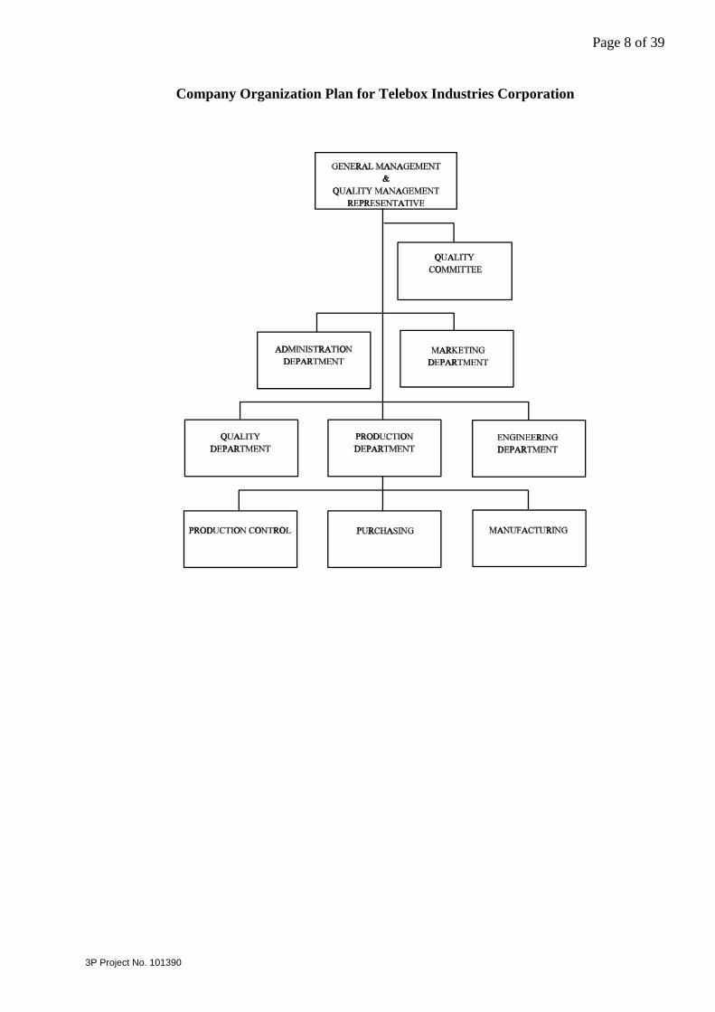
The overall company organisation plan of Telebox Industries Corporation is presented in page 8.
The following key management positions apply at Telebox Industries Corporation:
• General manager: Max Chu• Product Manager: Ray Chang• Quality Manager: Rita Chu
It is concluded that quality assurance is independant of production. Quality assurance andproduction are in the same level in organization.
5.2 Quality Assurance
Quality manager of Telebox Industries Corporation is Rita Chu.
The managers of the administration, marketing, engineering and production departments aremembers of a quality committee together with the quality manager and general manager. Thequality committee meets on a monthly basis and is the forum in which general discussions andfinal conclusion of quality issues are taken.
Telebox Industries Corporation has quality assurance approved according to ISO 9001. Approvalswere granted by TÜV CERT Certification Body of TÜV Rheinland, Germany", Certificate No.09 100 4834 dated 1998.03.11 with latest renewal date December 2000.
The quality handbook was inspected by 3P during the maintenance visit without giving cause toremarks.
Traceability of connecting hardware performance applies at Telebox Industries Corporation by thePCB producer code and production date identifications.
The quality assurance system at Telebox Industries Corporation is recognized by the followingcompanies and organisations:
• TÜV Rheinland
Page 8 of 39
3P Project No. 101390
Company Organization Plan for Telebox Industries Corporation

Page 9 of 39
3P Project No. 101390
A quality record of subsuppliers is kept and maintained by Telebox Industries Corporation. Allsupplied printed wiring boards are identified by design version and with codes for producer andproduction time.
Plated wires are supplied with certificates for plating thicknesses.
All measuring and test equipment were properly identified with a tag showing instrument numberand calibration expiration date. Calibration data were properly filed. Calibration is carried out byexternal source (company IPE).
5 persons (7 % of total staff) and equipment operators are working with quality assurance andquality control at Telebox Industries Corporation.
5.3 Production Facilities
Telebox Industries Corporation has internal moulding and stamping of most critical plastic andmetallic parts. External supsuppliers are used for some non-critical connector parts. Manualassembly of the printed wiring boards is applied. After assembly there is an in-line visual controlof the mounted printed wiring boards.
All prited wiring boards are tested for continuity.
5.4 Final Testing
Final testing at Telebox Industries Corporation has been stated as follows:
• Visual inspection: 100 %• Continuity testing (DC): 100 %• Insulation between conductors: 100 %• Near End Crosstalk measurements: 0,1 % for values at 100 MHz
Approx. once per day for recording in fullbandwidth
• Far End Crosstalk measurements: 0,1 % for values at 100 MHzApprox. once per day for recording in fullbandwidth
• Insertion loss and return lossmeasurements: Not regularly performed
Test results are stored in the quality department for three years.
The following instruments were applied at Telebox for performing the ongoing quality assurancetesting:
High Frequency Testing:
• HP Network Analyzer, type 8753E• BH Electronics Baluns, type 040-0093• North Hills Baluns, type 0322 BFX• 3P Baluns, type 3P-250-Cat6-C

Page 10 of 39
3P Project No. 101390
DC Resistance and Short Circuit Testing:
• Telebox Industries Corporation automatic DC test equipment• Instek LCR Meter, type LCR-819• Instek 2 Channel Millivoltmeter, type GCT-427B• Chen Hwa Milliohmmeter, type 502AC
Page 11 of 39
3P Project No. 101390
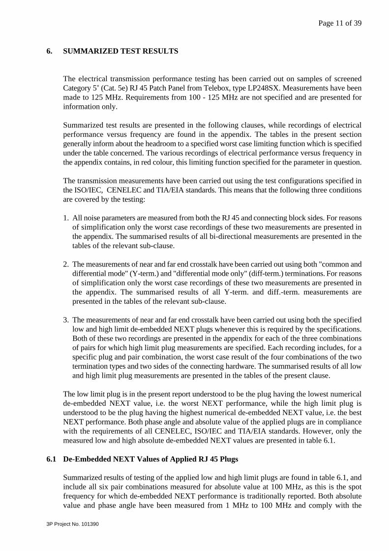
6. SUMMARIZED TEST RESULTS
The electrical transmission performance testing has been carried out on samples of screenedCategory 5 (Cat. 5e) RJ 45 Patch Panel from Telebox, type LP248SX. Measurements have been+
made to 125 MHz. Requirements from 100 - 125 MHz are not specified and are presented forinformation only.
Summarized test results are presented in the following clauses, while recordings of electricalperformance versus frequency are found in the appendix. The tables in the present sectiongenerally inform about the headroom to a specified worst case limiting function which is specifiedunder the table concerned. The various recordings of electrical performance versus frequency inthe appendix contains, in red colour, this limiting function specified for the parameter in question.
The transmission measurements have been carried out using the test configurations specified inthe ISO/IEC, CENELEC and TIA/EIA standards. This means that the following three conditionsare covered by the testing:
1. All noise parameters are measured from both the RJ 45 and connecting block sides. For reasonsof simplification only the worst case recordings of these two measurements are presented inthe appendix. The summarised results of all bi-directional measurements are presented in thetables of the relevant sub-clause.
2. The measurements of near and far end crosstalk have been carried out using both "common anddifferential mode" (Y-term.) and "differential mode only" (diff-term.) terminations. For reasonsof simplification only the worst case recordings of these two measurements are presented inthe appendix. The summarised results of all Y-term. and diff.-term. measurements arepresented in the tables of the relevant sub-clause.
3. The measurements of near and far end crosstalk have been carried out using both the specifiedlow and high limit de-embedded NEXT plugs whenever this is required by the specifications.Both of these two recordings are presented in the appendix for each of the three combinationsof pairs for which high limit plug measurements are specified. Each recording includes, for aspecific plug and pair combination, the worst case result of the four combinations of the twotermination types and two sides of the connecting hardware. The summarised results of all lowand high limit plug measurements are presented in the tables of the present clause.
The low limit plug is in the present report understood to be the plug having the lowest numericalde-embedded NEXT value, i.e. the worst NEXT performance, while the high limit plug isunderstood to be the plug having the highest numerical de-embedded NEXT value, i.e. the bestNEXT performance. Both phase angle and absolute value of the applied plugs are in compliancewith the requirements of all CENELEC, ISO/IEC and TIA/EIA standards. However, only themeasured low and high absolute de-embedded NEXT values are presented in table 6.1.
6.1 De-Embedded NEXT Values of Applied RJ 45 Plugs
Summarized results of testing of the applied low and high limit plugs are found in table 6.1, andinclude all six pair combinations measured for absolute value at 100 MHz, as this is the spotfrequency for which de-embedded NEXT performance is traditionally reported. Both absolutevalue and phase angle have been measured from 1 MHz to 100 MHz and comply with the
Page 12 of 39
3P Project No. 101390
specified limits in the full frequency range for all six pair combinations of applied plugs.
However, for simplification these test data are neither presented in table 6.1 nor as recordings inthe appendix.
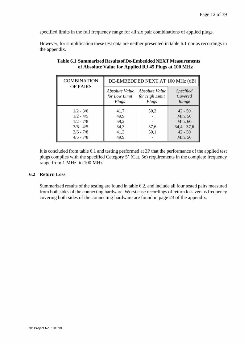
Table 6.1 Summarized Results of De-Embedded NEXT Measurementsof Absolute Value for Applied RJ 45 Plugs at 100 MHz
COMBINATIONOF PAIRS
DE-EMBEDDED NEXT AT 100 MHz (dB)
Absolute Valuefor Low Limit
Plugs
Absolute Valuefor High Limit
Plugs
SpecifiedCoveredRange
1/2 - 3/61/2 - 4/51/2 - 7/83/6 - 4/53/6 - 7/84/5 - 7/8
41,749,959,234,341,349,9
50,2--
37,650,1
-
42 - 50Min. 50Min. 60
34,4 - 37,642 - 50Min. 50
It is concluded from table 6.1 and testing performed at 3P that the performance of the applied testplugs complies with the specified Category 5 (Cat. 5e) requirements in the complete frequency+
range from 1 MHz to 100 MHz.
6.2 Return Loss
Summarized results of the testing are found in table 6.2, and include all four tested pairs measuredfrom both sides of the connecting hardware. Worst case recordings of return loss versus frequencycovering both sides of the connecting hardware are found in page 23 of the appendix.

Page 13 of 39
3P Project No. 101390
Table 6.2 Summarized Results of Return Loss Mea-surements from 1 MHz to 125 MHz
PAIR RETURN LOSSMARGIN TO LIMIT (dB)1
1-100 MHz2 100-125 MHz2
1/23/64/57/8
22,7 (24,2)10,3 (10,0)11,8 (12,3) 5,6 ( 5,8)
21,7 (23,2)10,2 ( 9,6)11,4 (12,1) 5,7 ( 6,3)
: Return Loss requirements are defined by the function:1
60-20log(f) dB,
where f is frequency in MHz. Calculated requirements below30 dB are equaled to this value. Specified requirements only applyfrom 1 MHz to 100 MHz.
: The first value represents measurement from the RJ 45 plug side,2
while the corresponding measurement from the connecting blockside is presented in brackets.
It is concluded from table 6.2 and return loss recordings in page 23 that return loss complies withthe specified Category 5 (Cat. 5e) requirements in the complete frequency range from 1 MHz+
to 100 MHz for both sides of the connecting hardware.
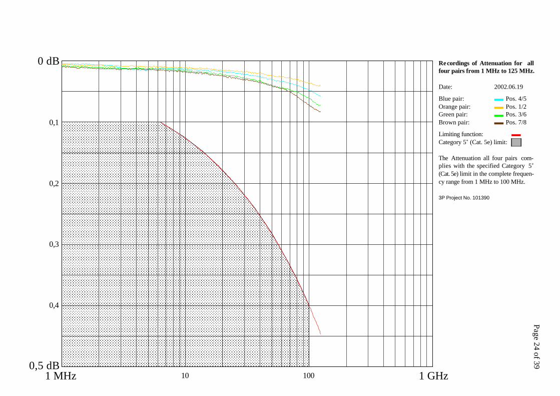
6.3 Attenuation
Summarized results of the testing are found in table 6.3, and include all four tested pairs measuredfrom one side of the connecting hardware. Recordings of attenuation versus frequency are foundin page 24 of the appendix.

Page 14 of 39
3P Project No. 101390
Table 6.3 Summarized Results of Attenuation Measurementsfrom 1 MHz to 125 MHz
PAIR MAX. ATTENUATION (dB)1 ATTENUATIONMARGIN TOLIMIT (%)1
1MHz
10MHz
100MHz
125MHz
1 - 100MHz
100 - 125MHz
1/23/64/57/8
0,010,010,010,01
0,010,020,010,02
0,030,060,050,07
0,040,070,060,08
89858482
90838781
Specified 0,10 0,13 0,40 0,45 0 -
: Attenuation requirements are defined by the function: 1
0,04 dB,
where f is frequency in MHz. Calculated requirements below 0,1 dB are equaledto this value. Specified requirements only apply from 1 MHz to 100 MHz.
It is concluded from table 6.3 and attenuation recordings in page 24 that attenuation complies withthe specified Category 5 (Cat. 5e) requirements in the complete frequency range from 1 MHz+
to 100 MHz.
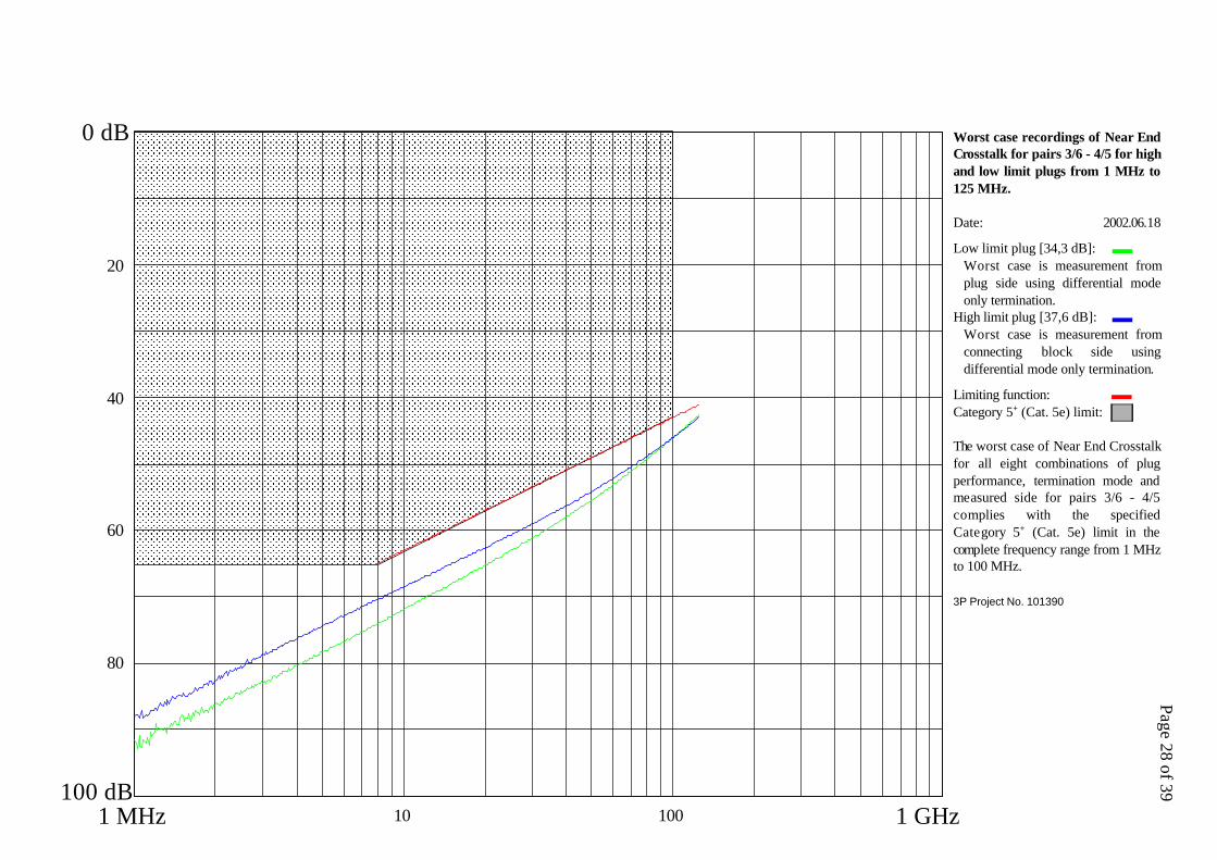
6.4 Near End Crosstalk
Summarized results of the testing are found in table 6.4, and include all six combinations of thefour tested pairs measured with both low and high limit plugs, using both Y-term. and diff.-term.terminations and seen from both sides of the connecting hardware. Worst case recordings of pair-pair near end crosstalk versus frequency for both low and high limit plug measurements, eachcovering the four combinations of termination types and sides of the connecting hardware, arefound in pages 25 - 30 of the appendix.
Page 15 of 39
3P Project No. 101390
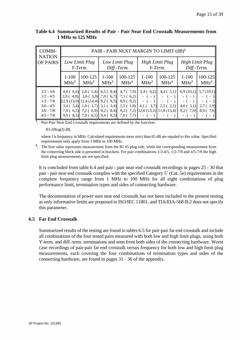
Table 6.4 Summarized Results of Pair - Pair Near End Crosstalk Measurements from1 MHz to 125 MHz
COMBI-NATION
OF PAIRS
PAIR - PAIR NEXT MARGIN TO LIMIT (dB)1
Low Limit PlugY-Term.
Low Limit PlugDiff.-Term.
High Limit PlugY-Term.
High Limit PlugDiff.-Term.
1-100MHz2
100-125MHz2
1-100MHz2
100-125MHz2
1-100MHz2
100-125MHz2
1-100MHz2
100-125MHz2
1/2 - 3/61/2 - 4/51/2 - 7/83/6 - 4/53/6 - 7/84/5 - 7/8
4,6 ( 6,6) 3,9 ( 4,0)12,9 (13,0) 3,4 ( 3,4) 7,0 ( 6,5) 9,0 ( 8,5)
2,8 ( 5,4) 3,6 ( 3,9) 12,4 (14,4) 1,8 ( 1,7) 7,2 ( 6,9) 7,0 ( 6,5)
6,5 ( 8,4) 7,0 ( 6,7) 9,2 ( 9,5) 3,1 ( 3,4) 9,2 ( 8,4) 9,4 ( 9,3)
4,7 ( 7,9) 7,1 ( 6,2) 8,9 ( 9,2) 1,5 ( 1,8) 9,2 ( 7,2) 7,6 ( 7,7)
5,4 ( 6,2) - ( - ) - ( - )
4,1 ( 3,7)12,0 (13,3) - ( - )
4,4 ( 5,1) - ( - ) - ( - ) 2,5 ( 2,5)11,8 (13,4) - ( - )
6,9 (10,1) - ( - ) - ( - )
4,0 ( 3,1) 9,2 ( 7,9) - ( - )
5,7 (10,1) - ( - ) - ( - )
2,7 ( 1,9) 8,9 ( 7,6) - ( - )
: Pair-Pair Near End Crosstalk requirements are defined by the function:1
83-20log(f) dB,
where f is frequency in MHz. Calculated requirements more strict than 65 dB are equaled to this value. Specifiedrequirements only apply from 1 MHz to 100 MHz.
: The first value represents measurement from the RJ 45 plug side, while the corresponding measurement from2
the connecting block side is presented in brackets. For pair combinations 1/2-4/5, 1/2-7/8 and 4/5-7/8 the highlimit plug measurements are not specified.
It is concluded from table 6.4 and pair - pair near end crosstalk recordings in pages 25 - 30 thatpair - pair near end crosstalk complies with the specified Category 5 (Cat. 5e) requirements in the+
complete frequency range from 1 MHz to 100 MHz for all eight combinations of plugperformance limit, termination types and sides of connecting hardware.
The documentation of power sum near end crosstalk has not been included in the present testingas only informative limits are proposed in ISO/IEC 11801, and TIA/EIA-568-B.2 does not specifythis parameter.
6.5 Far End Crosstalk
Summarized results of the testing are found in tables 6.5 for pair-pair far end crosstalk and includeall combinations of the four tested pairs measured with both low and high limit plugs, using bothY-term. and diff.-term. terminations and seen from both sides of the connecting hardware. Worstcase recordings of pair-pair far end crosstalk versus frequency for both low and high limit plugmeasurements, each covering the four combinations of termination types and sides of theconnecting hardware, are found in pages 31 - 36 of the appendix.

Page 16 of 39
3P Project No. 101390
Table 6.5 Summarized Results of Pair - Pair Far End Crosstalk Measurements from1 MHz to 125 MHz
COMBI-NATION
OF PAIRS
PAIR - PAIR FEXT MARGIN TO LIMIT (dB)1
Low Limit PlugY-Term.
Low Limit PlugDiff.-Term.
High Limit PlugY-Term.
High Limit PlugDiff.-Term.
1-100MHz2
100-125MHz2
1-100MHz2
100-125MHz2
1-100MHz2
100-125MHz2
1-100MHz2
100-125MHz2
1/2 - 3/61/2 - 4/51/2 - 7/83/6 - 4/53/6 - 7/84/5 - 7/8
18,0 (18,0)21,2 (20,6)35,5 (36,0) 7,7 ( 7,7) 8,4 ( 8,5)18,3 (18,5)
19,0 (18,9)24,7 (24,7)34,7 (34,7) 9,0 ( 9,0) 9,8 ( 9,9)18,9 (18,9)
20,7 (20,8)16,2 (16,2)29,2 (29,2) 7,8 ( 7,8) 6,9 (7,0)
16,8 (16,8)
21,8 (21,7)17,3 (16,9)27,4 (27,6) 9,1 ( 9,1) 8,0 ( 8,0)16,5 (16,5)
15,5 (15,5) - ( - ) - ( - )13,6 (13,5) 9,9 ( 9,9) - ( - )
16,2 (16,1) - ( - ) - ( - )15,1 (15,1)11,3 (11,3) - ( - )
13,7 (13,7) - ( - ) - ( - )13,7 (13,6) 8,6 ( 8,6) - ( - )
14,0 (14,0) - ( - ) - ( - )15,5 (15,5) 9,4 ( 9,4) - ( - )
: Pair-Pair Far End Crosstalk requirements are defined by the function:1
75,1-20log(f) dB,
where f is frequency in MHz. Calculated requirements more strict than 65 dB are equaled to this value. Specifiedrequirements only apply from 1 MHz to 100 MHz.
: The first value represents measurement from the RJ 45 plug side, while the corresponding measurement from2
the connecting block side is presented in brackets. For pair combinations 1/2-4/5, 1/2-7/8 and 4/5-7/8 the highlimit plug measurements are not specified.
It is concluded from table 6.5 and pair - pair far end crosstalk recordings in pages 31 - 36 that pair- pair far end crosstalk complies with the specified Category 5 (Cat. 5e) requirements in the+
complete frequency range from 1 MHz to 100 MHz for all eight combinations of plugperformance limit, termination types and sides of connecting hardware.
The documentation of power sum near end crosstalk has not been included in the present testingas only informative limits are proposed in ISO/IEC 11801, and TIA/EIA-568-B.2 does not specifythis parameter.
6.6 Input to Output Resistance
Results of the testing are found in table 6.6, and include all four tested pairs of the connectinghardware.

Page 17 of 39
3P Project No. 101390
Table 6.6 Results of Input to Output Resis-tance Measurements
CONDUCTORPATH
INPUT TO OUTPUTRESISTANCE
(mS)
12345678
2026274240414443
Specified Max. 200
It is concluded from table 6.6 that input to output resistance complies with the specifiedCategory 5 (Cat. 5e) requirements.+
6.7 Input to Output Resistance Unbalance
The worst case input to output resistance resistance unbalance is 24 mΩ, which is in compliancewith the specified max. 50 mΩ.
6.8 Current Carrying Capacity
Current carrying capacity has been measured by subjecting each conductor and the screen to asimultaneous exposure of 0,75 A at 60EC for 30 minutes.
The increase in temperature was 4EC, which is in compliance with the specified max. 30EC.Continuity of conductor and screen paths was maintained. No degradation of connecting hardwarewas observed after the testing.
It is concluded that current carrying capacity complies with the specified Category 5 (Cat. 5e)+
requirements.
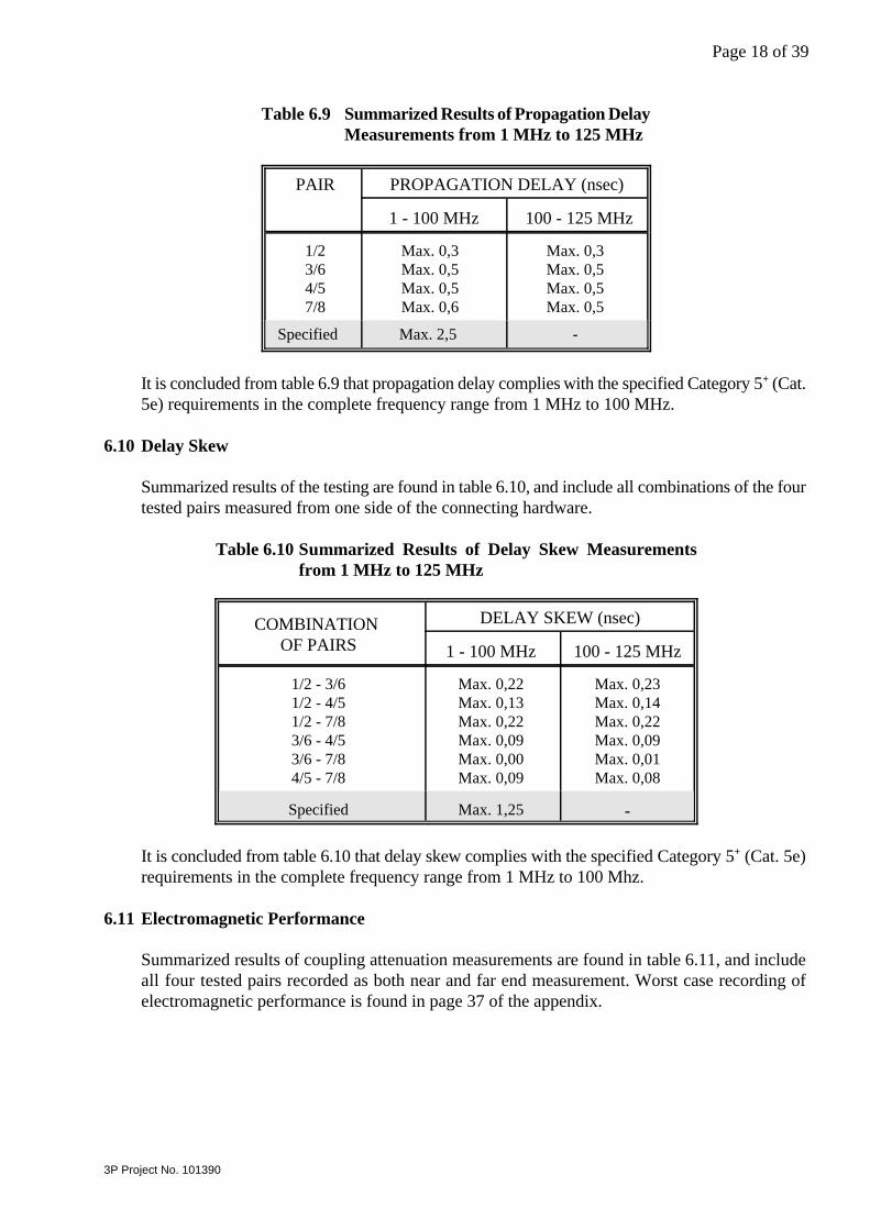
6.9 Propagation Delay
Summarized results of the testing are found in table 6.9, and include all four tested pairs of theconnecting hardware.
Page 18 of 39
3P Project No. 101390
Table 6.9 Summarized Results of Propagation DelayMeasurements from 1 MHz to 125 MHz
PAIR PROPAGATION DELAY (nsec)
1 - 100 MHz 100 - 125 MHz
1/23/64/57/8
Max. 0,3Max. 0,5Max. 0,5Max. 0,6
Max. 0,3Max. 0,5Max. 0,5Max. 0,5
Specified Max. 2,5 -
It is concluded from table 6.9 that propagation delay complies with the specified Category 5 (Cat.+
5e) requirements in the complete frequency range from 1 MHz to 100 MHz.
6.10 Delay Skew
Summarized results of the testing are found in table 6.10, and include all combinations of the fourtested pairs measured from one side of the connecting hardware.
Table 6.10 Summarized Results of Delay Skew Measurementsfrom 1 MHz to 125 MHz
COMBINATION OF PAIRS
DELAY SKEW (nsec)
1 - 100 MHz 100 - 125 MHz
1/2 - 3/61/2 - 4/51/2 - 7/83/6 - 4/53/6 - 7/84/5 - 7/8
Max. 0,22Max. 0,13Max. 0,22Max. 0,09Max. 0,00Max. 0,09
Max. 0,23Max. 0,14Max. 0,22Max. 0,09Max. 0,01Max. 0,08
Specified Max. 1,25 -
It is concluded from table 6.10 that delay skew complies with the specified Category 5 (Cat. 5e)+
requirements in the complete frequency range from 1 MHz to 100 Mhz.
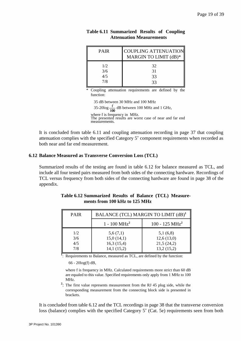
6.11 Electromagnetic Performance
Summarized results of coupling attenuation measurements are found in table 6.11, and includeall four tested pairs recorded as both near and far end measurement. Worst case recording ofelectromagnetic performance is found in page 37 of the appendix.
Page 19 of 39
3P Project No. 101390
Table 6.11 Summarized Results of CouplingAttenuation Measurements
PAIR COUPLING ATTENUATIONMARGIN TO LIMIT (dB)*
1/23/64/57/8
32313333
* Coupling attenuation requirements are defined by thefunction:
35 dB between 30 MHz and 100 MHz 35-20log dB between 100 MHz and 1 GHz,
where f is frequency in MHz.The presented results are worst case of near and far endmeasurements.
It is concluded from table 6.11 and coupling attenuation recording in page 37 that couplingattenuation complies with the specified Category 5 component requirements when recorded as+
both near and far end measurement.
6.12 Balance Measured as Transverse Conversion Loss (TCL)
Summarized results of the testing are found in table 6.12 for balance measured as TCL, andinclude all four tested pairs measured from both sides of the connecting hardware. Recordings ofTCL versus frequency from both sides of the connecting hardware are found in page 38 of theappendix.
Table 6.12 Summarized Results of Balance (TCL) Measure-ments from 100 kHz to 125 MHz
PAIR BALANCE (TCL) MARGIN TO LIMIT (dB)1
1 - 100 MHz2 100 - 125 MHz2
1/23/64/57/8
5,6 (7,1)15,0 (14,1)16,3 (15,4)14,1 (15,2)
5,1 (6,8)12,6 (13,0)21,5 (24,2)13,2 (15,2)
: Requirements to Balance, measured as TCL, are defined by the function:1
66 - 20log(f) dB,
where f is frequency in MHz. Calculated requirements more strict than 60 dBare equaled to this value. Specified requirements only apply from 1 MHz to 100MHz.
: The first value represents measurement from the RJ 45 plug side, while the2
corresponding measurement from the connecting block side is presented inbrackets.
It is concluded from table 6.12 and the TCL recordings in page 38 that the transverse conversionloss (balance) complies with the specified Category 5 (Cat. 5e) requirements seen from both+
Page 20 of 39
3P Project No. 101390
sides of the connecting hardware.
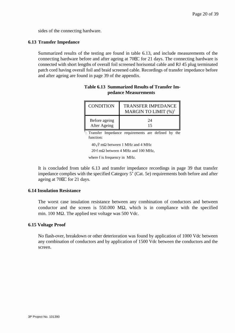
6.13 Transfer Impedance
Summarized results of the testing are found in table 6.13, and include measurements of theconnecting hardware before and after ageing at 70EC for 21 days. The connecting hardware isconnected with short lengths of overall foil screened horisontal cable and RJ 45 plug terminatedpatch cord having overall foil and braid screened cable. Recordings of transfer impedance beforeand after ageing are found in page 39 of the appendix.
Table 6.13 Summarized Results of Transfer Im-pedance Measurements
CONDITION TRANSFER IMPEDANCEMARGIN TO LIMIT (%)1
Before ageingAfter Ageing
2415
: Transfer Impedance requirements are defined by the1
function:
40 mΩ between 1 MHz and 4 MHz 20·f mΩ between 4 MHz and 100 MHz,
where f is frequency in MHz.
It is concluded from table 6.13 and transfer impedance recordings in page 39 that transferimpedance complies with the specified Category 5 (Cat. 5e) requirements both before and after+
ageing at 70EC for 21 days.
6.14 Insulation Resistance
The worst case insulation resistance between any combination of conductors and betweenconductor and the screen is 550.000 MΩ, which is in compliance with the specifiedmin. 100 MΩ. The applied test voltage was 500 Vdc.
6.15 Voltage Proof
No flash-over, breakdown or other deterioration was found by application of 1000 Vdc betweenany combination of conductors and by application of 1500 Vdc between the conductors and thescreen.
Page 21 of 39
3P Project No. 101390
7. CONCLUSION
Samples of screened Category 5 (Cat. 5e) connecting hardware from Telebox have been+
subjected to electrical transmission performance testing according to 3P requirements forScreened Category 5 (Cat. 5e) ISO/IEC, EN & TIA/EIA Connecting Hardware.+
The transmission performance of the screened Category 5 (Cat. 5e) connecting hardware from+
Telebox, type LP248SX does in every respect comply with the requirements of the followingrelevant international component standards and standard proposals:
• ISO/IEC 11801, Cat. 5• CENELEC EN 50173, Cat. 5• ISO/IEC Proposal for 2nd Edition 11801, Cat. 5:2000+• CENELEC Proposal for 2nd Edition EN 50173, Cat. 5:2000+• ANSI/TIA/EIA-568-B.2, Cat. 5e
The positive conclusion of the testing covers products from the qualified production line ofTelebox Industries Corporation having identical PCB circuit and, for screened connectinghardware, construction of screen. Presently this includes only Telebox Patch Panel, typeLP248SX.
The company
Telebox Industries Corporation4F, No. 306, Sec 1, Ta-Tung RoadHsi-Chin ChenTaipeiTaiwan, R.O.C.
is qualified at their Hsi-Chih site to produce the connecting hardware in question with a 3P ratingas Screened Category 5 (Cat. 5e) ISO/IEC, EN & TIA/EIA Connecting Hardware.+
The qualification will be valid until failure to pass one of the maintenance test programmes,which will be performed at 12 months intervals.
It should be noted that the present testing does not include the reliability test programmesspecified in CENELEC, ISO/IEC, IEC and TIA/EIA standards. Only the transmissionperformance is covered by the 3P qualification and listing of connecting hardware. It is assumedthat the contact reliability of the applied RJ 45 jacks is adequate to secure safe interconnectionto the patch cords throughout a lifetime of normal application of the connecting hardware.
Page 22 of 39
3P Project No. 101390
8. APPENDIX: Data Sheets of Transmission Performance versus Frequency
All characteristic and most critical recordings of transmission performance are presented in thefollowing way:
Page 23 Worst case recordings of return loss for all four pairs between 1 MHz and125 MHz.
Page 24 Recordings of attenuation for all four pairs between 1 MHz and 125 MHz.
Pages 25 - 30 Worst case recordings of pair-pair near end crosstalk for all six combinations ofpairs between 1 MHz and 125 MHz. Each page includes recordings of one specificpair combination measured using low and, if applicable, high limit plugs. For eachplug type the the recording is the worst case of four possible combinations of twotermination methods and two sides of the connecting hardware.
Pages 31 - 36 Worst case recordings of pair-pair far end crosstalk for all six combinations ofpairs between 1 MHz and 125 MHz. Each page includes recordings of one specificpair combination measured using low and, if applicable, high limit plugs. For eachplug type the the recording is the worst case of four possible combinations of twotermination methods and two sides of the connecting hardware.
Page 37 Worst case recording of electromagnetic performance between 30 MHz and1 GHz.
Page 38 Worst case recordings of balance measured as TCL for all four pairs between1 MHz and 125 MHz.
Page 39 Recordings of transfer impedance between 1 MHz and 100 MHz before and afterageing.

0 dB
1 MHz100 dB
40
80
10 1 GHz
60
Page 23 of 39
20
100
Worst case recordings of ReturnLoss for all four pairs from 1 MHz to125 MHz.
Date: 2002.06.19
Blue pair: Pair 4/5Worst case is measurement fromplug side.
Orange pair: Pair 1/2Worst case is measurement fromplug side.
Green pair: Pair 3/6Worst case is measurement fromconnecting block side.
Brown pair: Pair 7/8Worst case is measurement fromplug side.
Limiting function:Category 5 (Cat. 5e) limit:+
The worst case of Return Loss for allfour pairs complies with the specifiedCategory 5 (Cat. 5e) limit in the com-+
plete frequency range from 1 MHz to100 MHz.
3P Project No. 101390
0 dB
1 MHz
0,2
0,4
10 1 GHz
0,3
0,5 dB
Page 24 of 39
0,1
100
Recordings of Attenuation for allfour pairs from 1 MHz to 125 MHz.
Date: 2002.06.19
Blue pair: Pos. 4/5Orange pair: Pos. 1/2Green pair: Pos. 3/6Brown pair: Pos. 7/8
Limiting function:Category 5 (Cat. 5e) limit:+
The Attenuation all four pairs com-plies with the specified Category 5+
(Cat. 5e) limit in the complete frequen-cy range from 1 MHz to 100 MHz.
3P Project No. 101390

0 dB
1 MHz100 dB
40
80
10 1 GHz
20
100
60
Page 25 of 39
Worst case recordings of Near EndCrosstalk for pairs 1/2 - 3/6 for highand low limit plugs from 1 MHz to125 MHz.
Date: 2002.06.18
Low limit plug [41,7 dB]:Worst case is measurement fromplug side using common and diffe-rential mode termination.
High limit plug [50,2 dB]: Worst case is measurement fromplug side using common and diffe-rential mode termination.
Limiting function:Category 5 (Cat. 5e) limit:+
The worst case of Near End Crosstalkfor all eight combinations of plugperformance, termination mode andmeasured side for pairs 1/2 - 3/6complies with the specified Catego-ry 5 (Cat. 5e) limit in the complete+
frequency range from 1 MHz to100 MHz.
3P Project No. 101390

0 dB
1 MHz100 dB
40
80
1 GHz
20
60
10
Page 26 of 39
100
Worst case recording of Near EndCrosstalk for pairs 1/2 - 4/5 for lowlimit plug from 1 MHz to 125 MHz.
Date: 2002.06.18
Low limit plug [49,9 dB]:Worst case is measurement fromplug side using common and diffe-rential mode termination.
Limiting function:Category 5 (Cat. 5e) limit:+
The worst case of Near End Crosstalkfor all four combinations of termina-tion mode and measured side for pairs1/2 - 4/5 complies with the specifiedCategory 5 (Cat. 5e) limit in the com-+
plete frequency range from 1 MHz to100 MHz.
3P Project No. 101390

0 dB
1 MHz100 dB
40
80
1 GHz
20
60
10
Page 27 of 39
100
Worst case recording of Near EndCrosstalk for pairs 1/2 - 7/8 for lowlimit plug from 1 MHz to 125 MHz.
Date: 2002.06.18
Low limit plug [59,2 dB]:Worst case is measurement fromplug side using differential modeonly termination.
Limiting function:Category 5 (Cat. 5e) limit:+
The worst case of Near End Crosstalkfor all four combinations of termina-tion mode and measured side for pairs1/2 - 7/8 complies with the specifiedCategory 5 (Cat. 5e) limit in the com-+
plete frequency range from 1 MHz to100 MHz.
3P Project No. 101390
0 dB
1 MHz100 dB
40
80
1 GHz100
20
60
10
Page 28 of 39
Worst case recordings of Near EndCrosstalk for pairs 3/6 - 4/5 for highand low limit plugs from 1 MHz to125 MHz.
Date: 2002.06.18
Low limit plug [34,3 dB]:Worst case is measurement fromplug side using differential modeonly termination.
High limit plug [37,6 dB]: Worst case is measurement fromconnecting block side usingdifferential mode only termination.
Limiting function:Category 5 (Cat. 5e) limit:+
The worst case of Near End Crosstalkfor all eight combinations of plugperformance, termination mode andmeasured side for pairs 3/6 - 4/5complies with the specifiedCategory 5 (Cat. 5e) limit in the+
complete frequency range from 1 MHzto 100 MHz.
3P Project No. 101390

0 dB
1 MHz100 dB
40
80
1 GHz100
20
60
10
Page 29 of 39
Worst case recordings of Near EndCrosstalk for pairs 3/6 - 7/8 for highand low limit plugs from 1 MHz to125 MHz.
Date: 2002.06.18
Low limit plug [41,3 dB]:Worst case is measurement fromconnecting block side using commonand differential mode termination.
High limit plug [50,1 dB]: Worst case is measurement fromconnecting block side using differen-tial mode only termination.
Limiting function:Category 5 (Cat. 5e) limit:+
The worst case of Near End Crosstalkfor all eight combinations of plugperformance, termination mode andmeasured side for pairs 3/6 - 7/8complies with the specifiedCategory 5 (Cat. 5e) limit in the+
complete frequency range from 1 MHzto 100 MHz.
3P Project No. 101390

0 dB
1 MHz100 dB
40
80
1 GHz
20
60
10
Page 30 of 39
100
Worst case recording of Near EndCrosstalk for pairs 4/5 - 7/8 for lowlimit plug from 1 MHz to 125 MHz.
Date: 2001.06.18
Low limit plug [49,9 dB]:Worst case is measurement fromconecting block side using commonand differential mode termination.
Limiting function:Category 5 (Cat. 5e) limit:+
The worst case of Near End Crosstalkfor all four combinations of termina-tion mode and measured side for pairs4/5 - 7/8 complies with the specifiedCategory 5 (Cat. 5e) limit in the com-+
plete frequency range from 1 MHz to100 MHz.
3P Project No. 101390

0 dB
1 MHz100 dB
40
80
1 GHz
20
60
10
Page 31 of 39
100
Worst case recordings of Far EndCrosstalk for pairs 1/2 - 3/6 for highand low limit plugs from 1 MHz to125 MHz.
Date: 2002.06.19
Low limit plug [41,7 dB]:Worst case is measurement fromconnecting block side using commonand differential mode termination.
High limit plug [50,2 dB]: Worst case is measurement fromconnecting block side usingdifferential mode only termination.
Limiting function:Category 5 (Cat. 5e) limit:+
The worst case of Far End Crosstalkfor all eight combinations of plugperformance, termination mode andmeasured side for pairs 1/2 - 3/6complies with the specifiedCategory 5 (Cat. 5e) limit in the+
complete frequency range from 1 MHzto 100 MHz.
3P Project No. 101390

0 dB
1 MHz100 dB
40
80
1 GHz
20
60
10
Page 32 of 39
100
Worst case recording of Far EndCrosstalk for pairs 1/2- 4/5 for lowlimit plug from 1 MHz to 125 MHz.
Date: 2002.06.19
Low limit plug [49,9 dB]:Worst case is measurement fromconnecting block side using diffe-rential mode only termination.
Limiting function:Category 5 (Cat. 5e) limit:+
The worst case of Far End Crosstalkfor all four combinations of termina-tion mode and measured side for pairs1/2- 4/5 complies with the specifiedCategory 5 (Cat. 5e) limit in the com-+
plete frequency range from 1 MHz to100 MHz.
3P Project No. 101390

0 dB
1 MHz100 dB
40
80
1 GHz
20
60
10
Page 33 of 39
100
Worst case recording of Far EndCrosstalk for pairs 1/2 - 7/8 for lowlimit plug from 1 MHz to 125 MHz.
Date: 2002.06.19
Low limit plug [59,2 dB]:Worst case is measurement fromplug side using differential modeonly termination.
Limiting function:Category 5 (Cat. 5e) limit:+
The worst case of Far End Crosstalkfor all four combinations of termina-tion mode and measured side for pairs1/2 - 7/8 complies with the specifiedCategory 5 (Cat. 5e) limit in the com-+
plete frequency range from 1 MHz to100 MHz.
3P Project No. 101390
0 dB
1 MHz100 dB
40
80
1 GHz
20
60
10
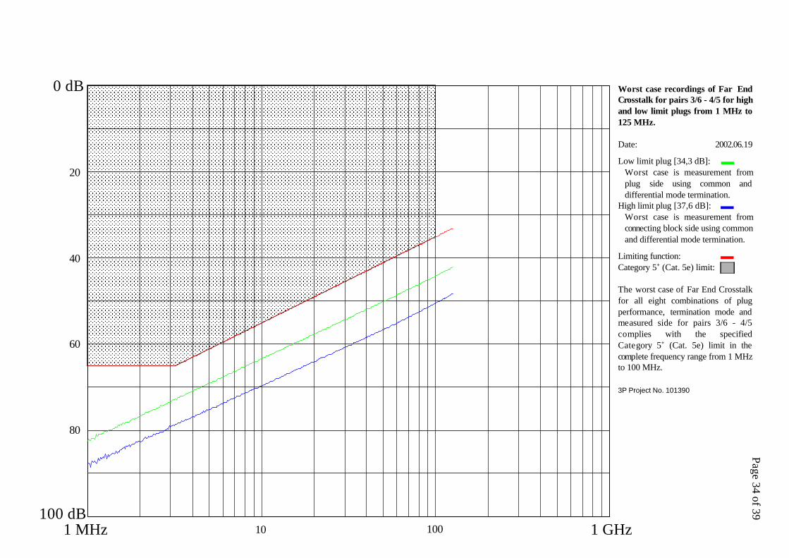
Page 34 of 39
100
Worst case recordings of Far EndCrosstalk for pairs 3/6 - 4/5 for highand low limit plugs from 1 MHz to125 MHz.
Date: 2002.06.19
Low limit plug [34,3 dB]:Worst case is measurement fromplug side using common anddifferential mode termination.
High limit plug [37,6 dB]: Worst case is measurement fromconnecting block side using commonand differential mode termination.
Limiting function:Category 5 (Cat. 5e) limit:+
The worst case of Far End Crosstalkfor all eight combinations of plugperformance, termination mode andmeasured side for pairs 3/6 - 4/5complies with the specifiedCategory 5 (Cat. 5e) limit in the+
complete frequency range from 1 MHzto 100 MHz.
3P Project No. 101390

0 dB
1 MHz100 dB
40
80
1 GHz
20
60
10
Page 35 of 39
100
Worst case recordings of Far EndCrosstalk for pairs 3/6 - 7/8 for highand low limit plugs from 1 MHz to125 MHz.
Date: 2002.05.19
Low limit plug [41,3 dB]:Worst case is measurement fromplug side using differential modeonly termination.
High limit plug [50,1 dB]: Worst case is measurement fromplug side using differential modeonly termination.
Limiting function:Category 5 (Cat. 5e) limit:+
The worst case of Far End Crosstalkfor all eight combinations of plugperformance, termination mode andmeasured side for pairs 3/6 - 7/8complies with the specifiedCategory 5 (Cat. 5e) limit in the+
complete frequency range from 1 MHzto 100 MHz.
3P Project No. 101390
0 dB
1 MHz100 dB
40
80
1 GHz
20
60
10
Page 36 of 39
100
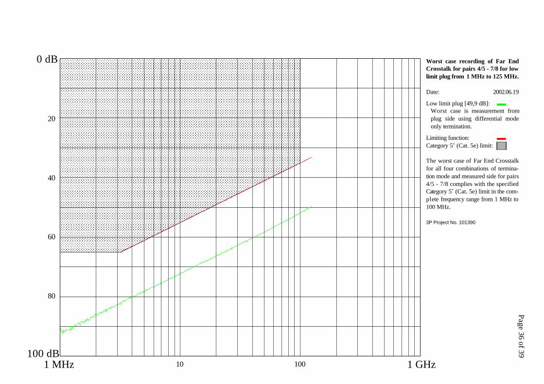
Worst case recording of Far EndCrosstalk for pairs 4/5 - 7/8 for lowlimit plug from 1 MHz to 125 MHz.
Date: 2002.06.19
Low limit plug [49,9 dB]:Worst case is measurement fromplug side using differential modeonly termination.
Limiting function:Category 5 (Cat. 5e) limit:+
The worst case of Far End Crosstalkfor all four combinations of termina-tion mode and measured side for pairs4/5 - 7/8 complies with the specifiedCategory 5 (Cat. 5e) limit in the com-+
plete frequency range from 1 MHz to100 MHz.
3P Project No. 101390

40
80
100 dB8006004000 MHz
0 dB
1 GHz200
20
60
Page 37 of 39
Worst case recording of EMC Per-formance from 30 MHz to 1 GHz.The measurement is based onrecordings of Coupling Attenuationfor all four pairs of the connectinghardware.
Measured on connecting hardwareassembled with an overall foil andbraid screened Category 5 (Cat. 5e)+
cable and tested in aerial span. Thecable alone was having EMC Perfor-mance of 93 dB.
Date: 2002.06.18
EMC Performance: 66 dB
Worst case is measurement fromconnecting block side.
The EMC Performance is derivedfrom the interception of a limitingfunction with the worst case Coup-ling Attenuation value at any frequ-ency for any pair. The constant valuefrom 30 MHz to 100 MHz is definedas the EMC Performance.
3P Project No. 101390

0 dB
1 MHz100 dB
40
80
10 1 GHz
60
Page 38 of 39
20
100
Worst case recordings of Balance(TCL) for all four pairs from 1 MHzto 125 MHz.
Date: 2002.06.18
Blue pair: Pair 4/5Worst case is measurement fromconnecting block side.
Orange pair: Pair 1/2Worst case is measurement fromplug side.
Green pair: Pair 3/6Worst case is measurement fromconnecting block side.
Brown pair: Pair 7/8Worst case is measurement fromplug side.
Limiting function:Category 5 (Cat. 5e) limit:+
The worst case of TransverseConversion Loss for all four pairscomplies with the specifiedCategory 5 (Cat. 5e) limit in the+
complete frequency range from 1 MHzto 100 MHz.
3P Project No. 101390
2000 mΩ
10 MHz
1600
1200
0 mΩ1 MHz 100 MHz
Page 39 of 39
800
400
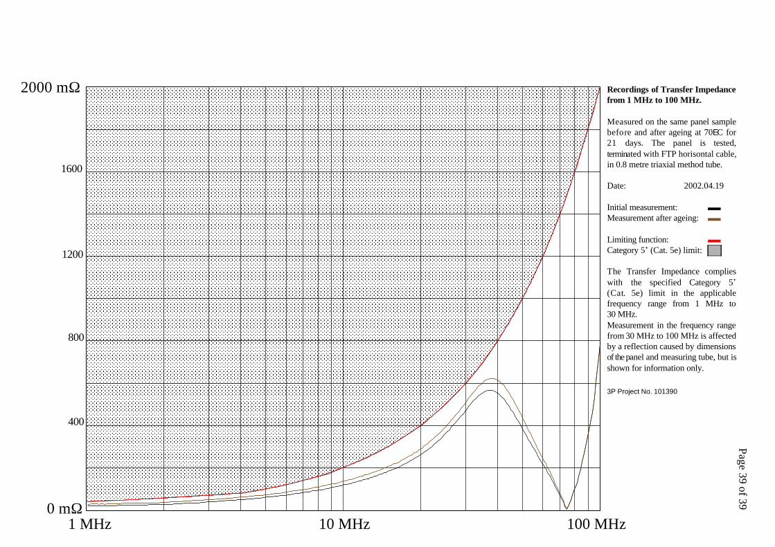
Recordings of Transfer Impedancefrom 1 MHz to 100 MHz.
Measured on the same panel samplebefore and after ageing at 70EC for21 days. The panel is tested,terminated with FTP horisontal cable,in 0.8 metre triaxial method tube.
Date: 2002.04.19
Initial measurement:Measurement after ageing:
Limiting function:Category 5 (Cat. 5e) limit:+
The Transfer Impedance complieswith the specified Category 5+
(Cat. 5e) limit in the applicablefrequency range from 1 MHz to30 MHz.Measurement in the frequency rangefrom 30 MHz to 100 MHz is affectedby a reflection caused by dimensionsof the panel and measuring tube, but isshown for information only.
3P Project No. 101390