qualcomm research 3gpp rel-12 dch enhancements · pdf filequalcomm research 3gpp rel-12 dch...
TRANSCRIPT

1
© 2015 Qualcomm Technologies, Inc.
Qualcomm Research
3GPP Rel-12 DCH Enhancements
January 2015
Qualcomm Research is a division of Qualcomm Technologies, Inc.
Title
Qualcomm Technologies, Inc.

2
© 2015 Qualcomm Technologies, Inc.
Qualcomm Technologies, Inc.
Qualcomm Technologies, Inc.
5775 Morehouse Drive
San Diego, CA 92121
U.S.A.
© 2015 Qualcomm Technologies, Inc.
All Rights Reserved.

3
© 2015 Qualcomm Technologies, Inc.
Table of Contents
Introduction 5
Rel-12 DCH Enhancements – common features 5
DL Pilot-Free Slot Formats 5
SRB Boosting on the DL 6
6
UL DPDCH 10ms Mode 6
UL DPDCH 10ms/20ms Switching 6
UL Signaling of 10ms Mode/20ms Mode Selection to NodeB Using TFCI 7
Basic configurations of DL DCH 7
DTX and DRX gaps 7
OLPC and Block-Error Rate (BLER) Target 8
Full configurations of DL DCH 8
Opportunistic DL Frame Early Termination (FET) 8
Transport Channel Concatenation 9
FET ACK 9
Compressed mode operation 9
CM without SF Reduction in DL 9
DCH Enhancements with CPC 10
Simulation results and performance 10
Data Throughput Improvement in Mixed Scenarios 10
UE Modem Current Improvement 12
Conclusion 13

4
© 2015 Qualcomm Technologies, Inc.
Figures
Figure 1 : Effect of pseudo-flexible rate matching ............................................................................................... 5
Figure 2 : Power scaling of DL DPDCH with POSRB. Here, α denotes the power adjustment due to power
control at slot k ..................................................................................................................................................... 6
Figure 3 : UL DPDCH 10ms Mode ...................................................................................................................... 6
Figure 4 : 10ms/20ms Switching State Machine .................................................................................................. 7
Figure 5 : DTX and DRX gaps in basic configuration ......................................................................................... 8
Figure 6 : Opportunistic FET using FET ACK/NACK sent over UL DPCCH .................................................... 9
Figure 7 : CM without SF reduction in Rel-12 DCH Enhancements ................................................................. 10
Figure 8 : HSDPA throughput increase with Rel-12 DCH Enhancements for various number of voice users .. 11
Figure 9 : HSUPA throughput increase with Rel-12 DCH Enhancements for various number of voice users .. 12
Figure 10 : Projected UE modem current savings with Rel-12 DCH Enhancements basic configuration ......... 12
5
© 2015 Qualcomm Technologies, Inc.
Introduction
The 3GPP Rel-99 standard is widely used around the world to carry circuit-switched voice
communications.3GPP Rel-12 Dedicated Channel (DCH) Enhancements aims at significantly improving
smartphones’ battery power consumption for voice communications, as well network’s uplink (UL) and
downlink (DL) capacity. This paper describes an overview of the Rel-12 DCH Enhancements.
Rel-12 DCH Enhancements – common features
DL Pilot-Free Slot Formats
Rel-12 DCH Enhancements introduces new slot formats for the DCH channel in DL to reduce the overhead
due to dedicated pilots. While in Rel-99, SIR estimation is based on dedicated pilots, SIR estimation can also
be based on TPC bits. Removal of dedicated pilots introduces some potential loss to SIR estimation, but it
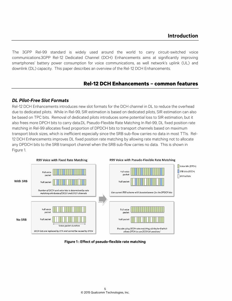
also frees more DPCH bits to carry data.DL Pseudo-Flexible Rate Matching In Rel-99, DL fixed position rate
matching in Rel-99 allocates fixed proportion of DPDCH bits to transport channels based on maximum
transport block sizes, which is inefficient especially since the SRB sub-flow carries no data in most TTIs. Rel-
12 DCH Enhancements improves DL fixed position rate matching by allowing rate matching not to allocate
any DPDCH bits to the SRB transport channel when the SRB sub-flow carries no data. This is shown in
Figure 1.
Figure 1 : Effect of pseudo-flexible rate matching

6
© 2015 Qualcomm Technologies, Inc.
SRB Boosting on the DL
Rel-12 DCH Enhancements provisions a power boost applied on DL DPDCH whenever SRBs are sent. Applying
a power boost to DL DPDCH in TTIs with SRB transmission offsets the effect of coding rate increase during
SRB transmission. Rel-12 DCH Enhancements introduces a power boost factor of POSRB to boost DPDCH in
TTIs with SRB transmission. Figure 2 outlines the application of POSRB to DL DPDCH when SRBs are sent.
UL DPDCH 10ms Mode
The DCH design in Rel-12 DCH Enhancements is based on the key idea of creating opportunities for the
receiver and transmitter to turn off (DRX and DTX, respectively) within the 20ms TTI of voice packets. The
UL DPDCH is compressed in a way that the data sent normally over 20ms periods is now sent in 10ms. In the
UL, DTX opportunities are created by introducing an UL 10ms Mode. In the 10ms Mode, UL DPDCH is
compressed over 10ms periods in every 20ms period. This is shown in Figure 3.
Figure 3 : UL DPDCH 10ms Mode
UL DPDCH 10ms/20ms Switching
The 10ms Mode requires to transmit UL DPDCH with a higher peak power. This can be challenging in power-
headroom (PH) limited scenarios, like at the cell edge. Rel-12 DCH Enhancements provision a mechanism for
New DPDCH packet every TTI
MAC Layer
PHY Layer
Compressed DPDCH Packet
DTX
10ms 10ms
Compressed DPDCH Packet
DTX
10ms 10ms
Figure 2 : Power scaling of DL DPDCH with POSRB. Here, α denotes the power adjustment due to power
control at slot k

7
© 2015 Qualcomm Technologies, Inc.
UL DPDCH transmission to switch between 10ms Mode and 20ms Mode where UL DPDCH frame structure
follows Rel-99. For fast response to changing channel conditions, the switching between 10ms Mode and 20ms
Mode is decided by the UE based on available power headroom. The switching is governed by a state machine
to control switching independently for each TFC.
Figure 4 : 10ms/20ms Switching State Machine
Figure 4 shows the state machine to govern 10ms/20ms switching for one TFC. If a TFC is allowed to be
sent in 10ms Mode, the network signals additional β gain factors or a reference TFC to compute the β
factors. In each TTI, the UE estimates the total transmit power needed to send the TFC in 10ms Mode using
the corresponding gain factors for 10ms Mode.
UL Signaling of 10ms Mode/20ms Mode Selection to NodeB Using TFCI
As the UE selects 10ms Mode or 20ms Mode, the NodeB needs to know which mode is used to decode the
uplink packet. This information is provided to the NodeB via uplink TFCI encoding. As the 10ms/20ms Mode
signaling occurs at TFCI encoding and decoding functions, the entire signaling is contained within the
physical-layer and is oblivious to higher layers.
Basic configurations of DL DCH
On the DL, Rel-12 DCH Enhancements allow for a basic configuration and a full configuration of DL DCH to
create DTX and DRX gaps at the NodeB and the UE, respectively.
DTX and DRX gaps
In the basic configuration, DL DRX opportunities at the UE are based on the UL 10ms Mode. When the UL is
in 10ms Mode and there are no SRBs sent on the DL, the UE stops listening to the DL DPCH in the second
10ms period of the 20ms voice TTI. When the UL is in 20ms Mode, the UE continues listening to the DL DPCH
for the entire 20ms voice TTI without DRXing. The DL always continues transmitting DCH for the entire TTI
when SRBs are sent. Figure 5 illustrates the DTX and DRX operations when SRBs are not sent.
10msMode
20msMode
Restrict
Revive

8
© 2015 Qualcomm Technologies, Inc.
Figure 5 : DTX and DRX gaps in basic configuration
When SRBs are sent, the DL DCH is continuously transmitted. When the UL is in 10ms Mode, the UL DPCCH
is absent in the second 10ms radio frame of the voice 20ms TTI, in which case, the DL DCH is transmitted at
a fixed power with ILPC turned off. When the UL is in 20ms Mode, the UL DPCCH is present for the entire
20ms voice TTI, and DL/UL DCH are sent with active ILPC.
OLPC and Block-Error Rate (BLER) Target
When the UL is 10ms Mode, effectively the OLPC maintains the network-signaled DL BLER target at 10ms
boundaries. Since the same BLER target is used, applying the BLER target at 10ms boundary ensures that
the statistics of voice-packet errors is the same as the block-error statistics in Rel-99. The DL voice quality in
10ms Mode is thus the same as Rel-99 DL.
Full configurations of DL DCH
In the full configuration, early termination of the DL DCH is dynamic, and is based on receiving an ACK
message on the uplink, indicating successful early decoding of the DL DCH packet.
Opportunistic DL Frame Early Termination (FET)
Instead of a fixed early termination target as in the basic configuration, the full configuration allows
opportunistic early termination, where the DL DCH is terminated only if the early decoding succeeds and an
ACK message is sent on the uplink. This opportunistic FET in a way introduces a form of HARQ for DL DCH,
making the DL DCH link more efficient than the basic configuration or Rel-99.
Using CRC, the UE can identify if an early decoding has successfully decoded the voice packet. The possibility
of multiple decoding attempts before success increases the probably of a false CRC pass, and thus in the full
configuration, a larger CRC size of 16 bits is used to increase CRC reliability.

9
© 2015 Qualcomm Technologies, Inc.
Transport Channel Concatenation
All voice transport channels are concatenated at the physical layer and are protected by a 16-bits CRC in the
full configuration. At the physical-layer level, the resulting concatenated transport channel is treated as a new
transport channel, inheriting the configuration parameters of the first sub-flow.
FET ACK
Opportunistic FET requires sending ACK message on the uplink to indicate successful decoding of the DL
DCH voice packet. A new UL DPCCH slot format 5 is introduced in Rel-12 DCH Enhancements in which the
two TFCI fields per slot are shared between encoded TFCI bits and FET ACK/NACK bits. As shown in Figure
6, FET NACK bits are sent prior to sending the FET ACK bits in a pair over two successive slots. Introducing
FET NACK bits and pairing of ACK bits helps to protect against false decoding of NACK bits as ACK, which
leads to unwanted frame early termination at the NodeB side.
Figure 6 : Opportunistic FET using FET ACK/NACK sent over UL DPCCH
Compressed mode operation
A key feature of the new CM operation is that in DL, spreading factor reduction by a factor of two is not
required, unlike Rel-99 CM. SF reduction during an active DCH call is problematic from an OVSF code
management perspective at the RNC.
CM without SF Reduction in DL
In the DL, the CM transmission gaps are created by blanking the DPCH slots that are in CM transmission gaps.
In the UL, the CM transmission gaps are created differently in the 10ms Mode and 20ms Mode. In the 10ms
Mode, the UL transmission of DPCH occupies only half of the 20ms voice TTI. The DTX gaps in UL
transmission in 10ms Mode can well be used to accommodate the UL CM transmission gaps. If the TG overlaps
with the first 10ms radio frame in a 20ms voice TTI, the UL DPCH frame simply wraps around the TG, by

10
© 2015 Qualcomm Technologies, Inc.
skipping the slots that are in the transmission gap. In the UL 20ms Mode, the transmission gaps are created
using the same mechanism as the one in Rel-99. See the timeline of DL DPCH in Figure 7.
Figure 7 : CM without SF reduction in Rel-12 DCH Enhancements
DCH Enhancements with CPC
CPC, or continuous packet connectivity, allows for DTX and DRX operations during HS calls. Rel-12 DCH
Enhancements allows to have CPC together with DCH, enabling battery efficient multi-RAB calls. Rel-12 DCH
Enhancements allows for a simple operation together with CPC in which DTX or DRX at the UE side is allowed
only if DTX or DRX is allowed according to both CPC rules and DCH Enhancement DTX and DRX. In other
words, DTX and DRX operation in multi-RAB calls of HS and DCH is opportunistic.
Simulation results and performance
Rel-12 DCH Enhancements provides DL and UL link efficiency gains over Rel-99 DCH and improves UE battery
life. The link efficiency of Rel-12 DCH Enhancements also improves the data throughput due to less transmit
power requirement per voice call in Rel-12 DCH Enhancements.
Data Throughput Improvement in Mixed Scenarios
For various number of voice users, Figure 8 shows the HSPDA absolute throughput with Rel-99, Rel-12 DCH
Enhancements basic configuration, and Rel-12 DCH Enhancements full configuration. AMR 12.2kbps codec
is assumed, and ITU channels are used with a mixture of 30% PA3, 30% PB3, 20% VA30, and 20% VA120. An
inter-site distance (ISD) of 1Km is assumed. See [3GPP TR 25.702, study on DCH Enhancements] for a
11
© 2015 Qualcomm Technologies, Inc.
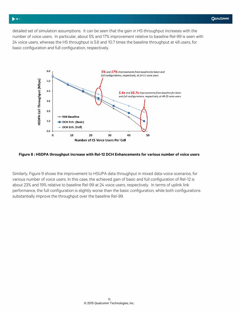
detailed set of simulation assumptions. It can be seen that the gain in HS throughput increases with the
number of voice users. In particular, about 5% and 17% improvement relative to baseline Rel-99 is seen with
24 voice users, whereas the HS throughput is 5.6 and 10.7 times the baseline throughput at 48 users, for
basic configuration and full configuration, respectively.
Figure 8 : HSDPA throughput increase with Rel-12 DCH Enhancements for various number of voice users
Similarly, Figure 9 shows the improvement to HSUPA data throughput in mixed data-voice scenarios, for
various number of voice users. In this case, the achieved gain of basic and full configuration of Rel-12 is
about 23% and 19% relative to baseline Rel-99 at 24 voice users, respectively. In terms of uplink link
performance, the full configuration is slightly worse than the basic configuration, while both configurations
substantially improve the throughput over the baseline Rel-99.

12
© 2015 Qualcomm Technologies, Inc.
Figure 9 : HSUPA throughput increase with Rel-12 DCH Enhancements for various number of voice users
UE Modem Current Improvement
Figure 10 shows the projected UE modem current savings over Rel-99. The projections the figure are based
on potential current savings due to the modem analog receiver and transmitter front ends. In these
projections, the UE is assumed to be always in UL 10ms Mode, which should be the case in most scenarios.
At -5 to 0dBm transmit powers, a combination of DTX and DRX yields about 24-25% projected UE modem
current savings. At above 10dBm transmit powers, the basic configuration helps to save the UE modem
current by as much as 30 to 40%.
Figure 10 : Projected UE modem current savings with Rel-12 DCH Enhancements basic configuration
13
© 2015 Qualcomm Technologies, Inc.
Conclusion
Rel-12 DCH Enhancements builds upon Rel-99 to significantly improve key aspects of voice communications
in 3G UMTS systems. At the heart of Rel-12 DCH Enhancements, mechanisms for discontinuous transmission
of DL and UL DCH channel allow the UE transceiver to turn off, resulting in significant UE modem current
savings. On the uplink, discontinuous transmissions on the UL DCH results in less interference to other users,
providing significant uplink link performance improvements. On the DL, the full configuration of Rel-12 DCH
Enhancements allows for opportunistic frame early termination. The two configurations of Rel-12 DCH
Enhancements, the basic configuration and the full configuration, are designed to adhere to Rel-99 DCH frame
structure as much as possible to simply the implementation, while drastically improve key performance
aspects of Rel-99.