quadelectra - cv suite vectorizer operation manual if f.e. you connect a cv cable to "top"...
TRANSCRIPT


Page 3
Operation Manual
1. Welcome To Quadelectra CV Suite Vectorizer Welcome to Quadelectra CV Suite Vectorizer Rack Extension for Reason. We would like to thank you for purchasing / trying this product, since we feel that this is a recognition of our hard work. CV Suite Vectorizer is an XY Pad Controller for Propellerhead Reason 7.0 and above. Nevertheless as we usually do, we have equipped this unit with features that you can't find in any other product. An XY-Pad uses a touch screen or a joystick to allow the user to control more than one parameter with a single movement. CV Suite Vectorizer brings this functionality to Reason's virtual Rack. Traditionally XY-Pads where heavily used in Vector Synthesis where, under the most common scenario, four different sound timbres where mixed according to the X & Y co-ordinates of a joystick, to synthesize a new sound. CV Suite Vectorizer is named after the "Vector Synthesis" term. Nevertheless the Quadelectra CV Suite Vectorizer is a CV controller, which means that you can use, the XY-Pad functionality to control all kinds of CV inputs, not just mix four different sounds. In Reason, an XY Pad functionality example, can be found in Thor's Formant Filter module, where the "vowels" are controlled by the user using a virtual XY touch pad. We hope that you'll enjoy using the Quadelectra CV Suite Vectorizer.

Page 4
Operation Manual
2. Features
2.1. Four Directional Control. Quadelectra CV Suite Vectorizer provides simultaneous control over four basic parameters (plus two extra parameters, we'll examine later on). The four parameters are named and can be identified by the names of the four sides of a rectangle: TOP, BOTTOM, LEFT & RIGHT. So if f.e. you connect a CV cable to "Top" CV output #1, the controlled parameter will change whenever you move the touch point up or down. Consequently connecting a CV cable to "Left" CV output #1, the controlled parameter will change whenever you move the touch point left or right. As you move towards a side of the rectangle, the value of the parameter for that side is increased. So moving towards "Bottom" increases the CV value for "Bottom" parameter, whereas moving towards "Right" increases the CV value for "Right" parameter. By Default all parameters should be considered bipolar (between -1.0 and +1.0). With the touch point at middle-center, all parameters are set to 0.0. Note that it is not mandatory to use all four parameters.
2.2. Parameter Customization. CV Suite Vectorizer provides a set of controls to allow you to customize the parameter values you receive from the touch pad.
1. Scaling: A parameter can be scaled from 0% to 100%. This is a multiplier for the value returned by the touch pad. At 0% no touch pad value passes through. At 100% (rightmost position) the full value range from the touch pad passes through.
fig.2.2.1: The Reference Signal Scaled at 100% (no change), at 50%, and at 0%.
2. Offset: An additional offset can be applied to the parameter. The offset alters the middle point (0.0) by a value inside the normalized bipolar range (-1.0 to +1.0). Values outside the normal BP range, caused by the offset, are clamped.
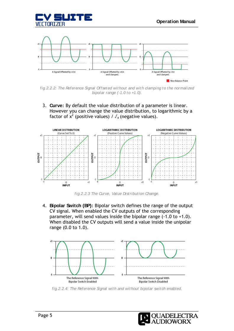
Page 5
Operation Manual
fig.2.2.2: The Reference Signal Offseted without and with clamping to the normalized bipolar range (-1.0 to +1.0).
3. Curve: By default the value distribution of a parameter is linear.
However you can change the value distribution, to logarithmic by a factor of x2 (positive values) / √x (negative values).
fig.2.2.3 The Curve, Value Distribution Change.
4. Bipolar Switch (BP): Bipolar switch defines the range of the output CV signal. When enabled the CV outputs of the corresponding parameter, will send values inside the bipolar range (-1.0 to +1.0). When disabled the CV outputs will send a value inside the unipolar range (0.0 to 1.0).
fig.2.2.4: The Reference Signal with and without bipolar switch enabled.
Page 6
Operation Manual
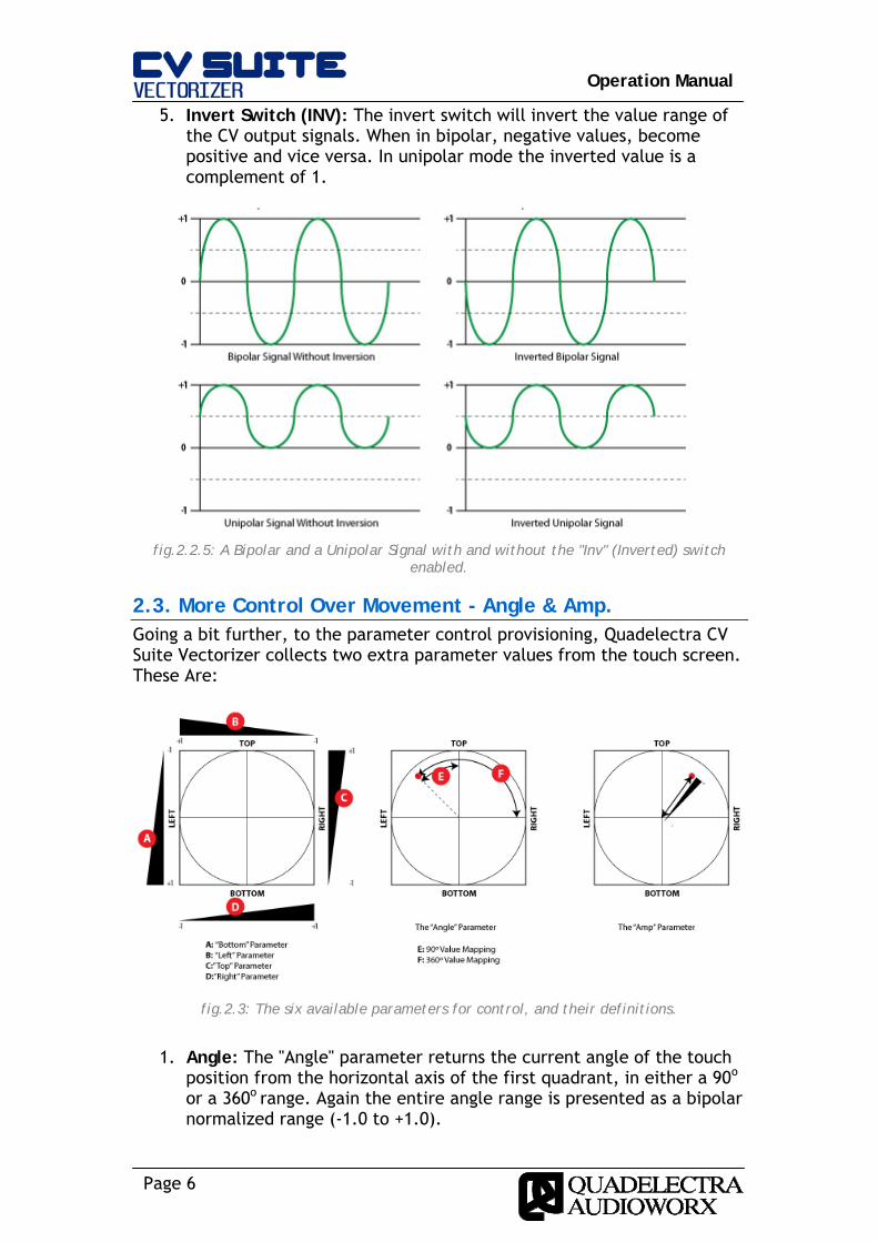
5. Invert Switch (INV): The invert switch will invert the value range of the CV output signals. When in bipolar, negative values, become positive and vice versa. In unipolar mode the inverted value is a complement of 1.
fig.2.2.5: A Bipolar and a Unipolar Signal with and without the "Inv" (Inverted) switch
enabled.
2.3. More Control Over Movement - Angle & Amp. Going a bit further, to the parameter control provisioning, Quadelectra CV Suite Vectorizer collects two extra parameter values from the touch screen. These Are:
fig.2.3: The six available parameters for control, and their definitions.
1. Angle: The "Angle" parameter returns the current angle of the touch
position from the horizontal axis of the first quadrant, in either a 90o
or a 360o range. Again the entire angle range is presented as a bipolar normalized range (-1.0 to +1.0).

Page 7
Operation Manual
When Value Mapping is set at 90o the CV Vectorizer will map the each odd quadrant to the bipolar range, and each even quadrant to the inverse bipolar range. This provides a continuous smooth value range to the angle parameter. At 360o Value Mapping, CV Suite Vectorizer maps the entire axis of the center to the bipolar range. This means that the acquired angle value will jump from -1.0 to +1.0 if the touch point is moved from 359.9o to 0o.
2. Amp: The "Amplitude" parameter returns a value that corresponds to the distance between the center of the touch pad and the touch point. The amp value is constrained inside the boundaries of the circle grid. When outside this region, the touch point always returns 1.0.
2.4. External Modulation. The four main parameters "Top", "Bottom", "Left" and "Right" have their own modulation input sources at the back panel of the device. Additionally a set of four knobs, one for each parameter respectively, situated at the left side of the front panel, control the amount of the external modulation to the parameters. The knobs work like the "Scale" multipliers, but they are bipolar. So you can use them not just for scaling, but also for inverting the external input signals.
2.5. Glide Updates to parameters from the touch screen can occur rapidly, or you can use the "Glide" knob to increase the time between a change transition, to achieve a smoother result. The "Glide" knob can transition an update from 0 to 1000ms.
2.6. Value Quantization A very useful feature found in Quadelectra CV Suite Vectorizer, is the quantization modes, independent for both X and Y axis. Yes! This means that you can split the entire range into segments and have your parameter values lock on them. The quantization ranges from 0 (no quantization) to 127. When set to a number lower than 64 segments, a grid showing the available positions is displayed, in the touch screen. The cursor changes accordingly to a rectangle reflecting the position of the current selected vertical and / or horizontal segment. Some examples of display changes, on this feature, are given below:

Page 8
Operation Manual
fig.2.6.1: The touch screen display will display a grid and change the cursor to a rectangle reflecting the current vertical or horizontal quantization segment.
2.7. Recording Automation Unfortunately due to technical limitations, you cannot enable automation for the X-Y Pad by Alt+Clicking (Option + Click on Mac) onto it, for the moment. Nevertheless, you can record X-Y Pad automation, simply by selecting the CV Suite Vectorizer track and hitting the Record Button. Another way is, by selecting either the “XY Pad: Touch X” or “XY Pad: Touch Y” parameter from the device’s automation combo box.
Fig.2.7: Selecting XY Pad: Touch X or Touch Y from the device’s combo box.

Page 9
Operation Manual
3. The Front Panel The front panel is divided in to 4 different regions.
fig.3: The Quadelectra CV Suite Vectorizer front panel
3.1. External Modifiers Amount. The External Modifiers Amount section, has four knobs corresponding to the main touch screen parameters ("Top", "Bottom", "Left", "Right"). These knobs regulate the amount of signal and the polarity that's applied to each parameter from a corresponding external modifier input at the back panel.
3.2. Global Settings The global settings of the device, can be found under this section. These are (from left to right):
1. Glide: The transition time between changes. Can vary from 0ms (no transition) to 1000ms.
2. Use X/Y Axis: These two switches enable or disable the usage of the vertical or horizontal axis, to control parameters. When an axis is disabled the parameter values for that axis, are set to zero. Further modifications from the output settings, still apply for the said parameters. Typically disabling an axis, its like turning it's Quantize number of segments to 1.
3. Quantize X/Y: This parameter quantizes the entire range of available values of the horizontal or / and vertical axis, by a factor.
3.3. XY Touch Screen This is the main control of the Quadelectra CV Suite Vectorizer. The red mark on the screen, displays the current value of the XY Pad. When quantization is off, this is the point from the last time you touched the virtual touch screen. By "tapping" or "dragging" the cursor on the virtual screen, you change all six CV Suite Vectorizer parameters simultaneously.

Page 10
Operation Manual
When in quantization mode, the red circle changes to a rectangular cursor that occupies the entire segment of the current quantized value.
3.4. Output Settings The Output Settings section deals with further modification of the values for each of the six available CV Suite Vectorizer parameters. The parameters you can customize are:
1. Scale: A value expressed in percentage, that manages the amount of the signal passing through from the touch pad to the parameter. This works like a trim knob.
2. Offset: The offset knob, "moves" the balance point to a higher or lower value than 0.0. Occuring parameter values with an offset can exceed the normalized range, above or below +1.0 or -1.0 respectively, so for compliance reasons, they are clamped.
3. Curve: By altering this setting you can change the value distribution of a parameter, from linear to logarithmic by a factor of x2 (positive values) / √x (negative values). NOTE: This setting does not apply to the "Angle" parameter.
4. Value Mapping: This setting changes the way CV Suite Vectorizer, maps the value range of the touch point angle. At 90o the angle value transits smoothly between +1.0 and -1.0 per odd, and -1.0 to +1.0 per even quadrant. At 360o the entire angle axis is mapped to the bipolar range. NOTE: This setting applies only to the "Angle" parameter
5. BP (Bipolar): When the "Bipolar" switch is enabled, the final outcome from the parameter is preserved in between the bipolar range. With the "Bipolar" switch disabled, the value is scaled down between the unipolar range (0.0 to 1.0).
6. INV (Invert): The "Invert" switch inverts the values of the parameter. When in "Bipolar" mode ("BP" switch enabled), positive values are turned to negative, and vice versa. When in "Unipolar" mode ("BP" switch disabled), values turn to their complement of 1.
Page 11
Operation Manual
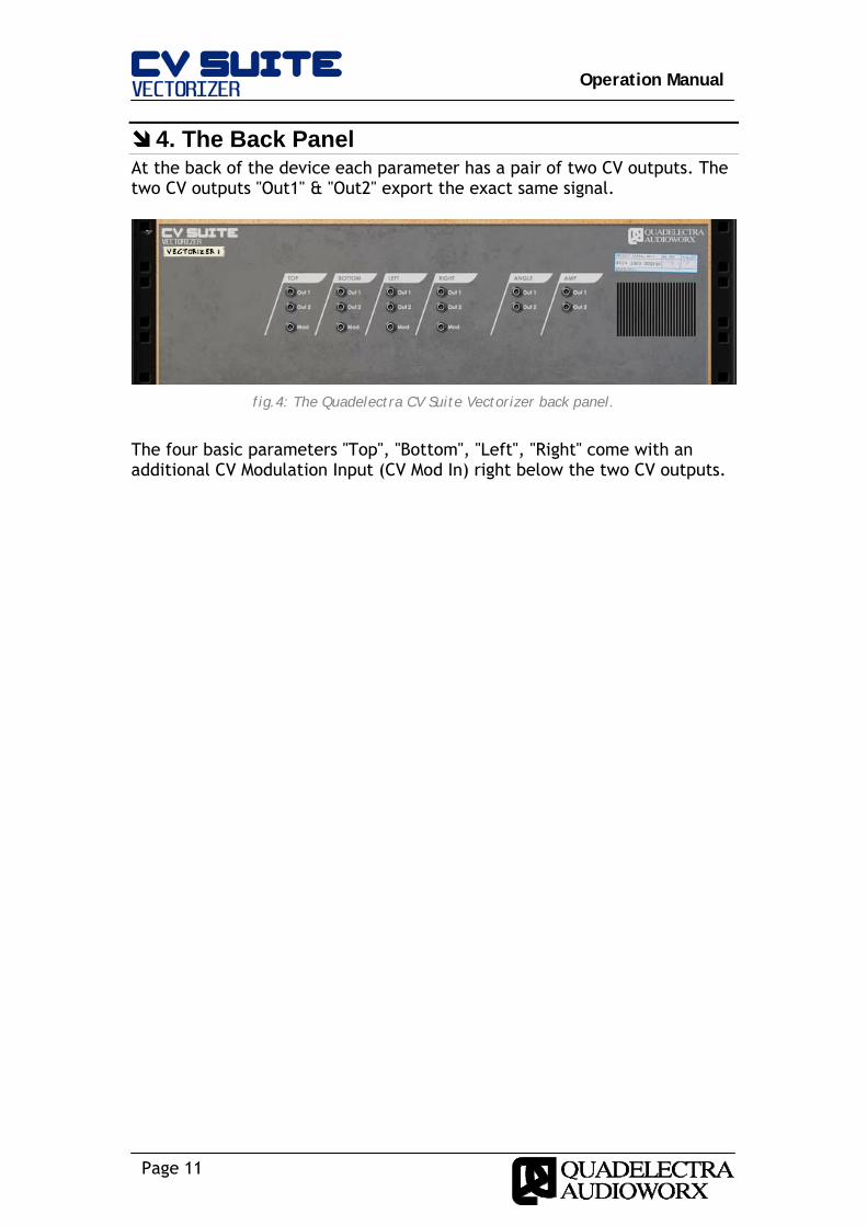
4. The Back Panel At the back of the device each parameter has a pair of two CV outputs. The two CV outputs "Out1" & "Out2" export the exact same signal.
fig.4: The Quadelectra CV Suite Vectorizer back panel.
The four basic parameters "Top", "Bottom", "Left", "Right" come with an additional CV Modulation Input (CV Mod In) right below the two CV outputs.

Page 12
Operation Manual
APPENDIX I: MIDI CC
MIDI CC # Parameter
5 Global: Glide Amount
12 Touchpad: Touch X
13 Touchpad: Touch Y
14 Global: Quantize X
15 Global: Quantize Y
16 Top: Mod Amount
17 Bottom: Mod Amount
18 Left: Mod Amount
19 Right: Mod Amount
102 Top: Scale
103 Top: Offset
104 Top: Curve
105 Top: BP (Bipolar) Switch
106 Top: INV (Inverse) Switch
107 Bottom: Scale
108 Bottom: Offset
109 Bottom: Curve
110 Bottom: BP (Bipolar) Switch
111 Bottom: INV (Inverse) Switch
112 Left: Scale
113 Left: Offset
114 Left: Curve
115 Left: BP (Bipolar) Switch
116 Left: INV (Inverse) Switch
117 Right: Scale
118 Right: Offset
119 Right: Curve

Operation Manual
Page 13
128 Right: BP (Bipolar) Switch
129 Right: INV (Inverse) Switch
130 Angle: Scale
131 Angle: Offset
132 Angle: 90o/360o Value Mapping
133 Angle: BP (Bipolar) Switch
134 Angle: INV (Inverse) Switch
135 Amp: Scale
136 Amp: Offset
137 Amp: Curve
138 Amp: BP (Bipolar) Switch
139 Amp: INV (Inverse) Switch
140 Global: Use X Axis
141 Global: Use Y Axis