quadcopter dynamics - center for air transportation...
TRANSCRIPT

Quadcopter Dynamics
1

Bréguet Richet Gyroplane No. 1 1907
• Brothers Louis Bréguet and Jacques Bréguet
• Guidance of Professor Charles Richet
• The first flight demonstration of Gyroplane No. 1 with no control surfaces was achieved on 29 September 1907.
https://www.youtube.com/watch?v=dff2erD_1PU 2

Jerome-de Bothezat Flying Octopus
• Georges de Bothezat and Ivan Jerome in 1922,
• 6-bladed rotors placed at each end of an X-shaped truss structure
• Built for US Army
– complexity, control difficulties, and high pilot workload, only capable of forward flight in a favorable wind
3
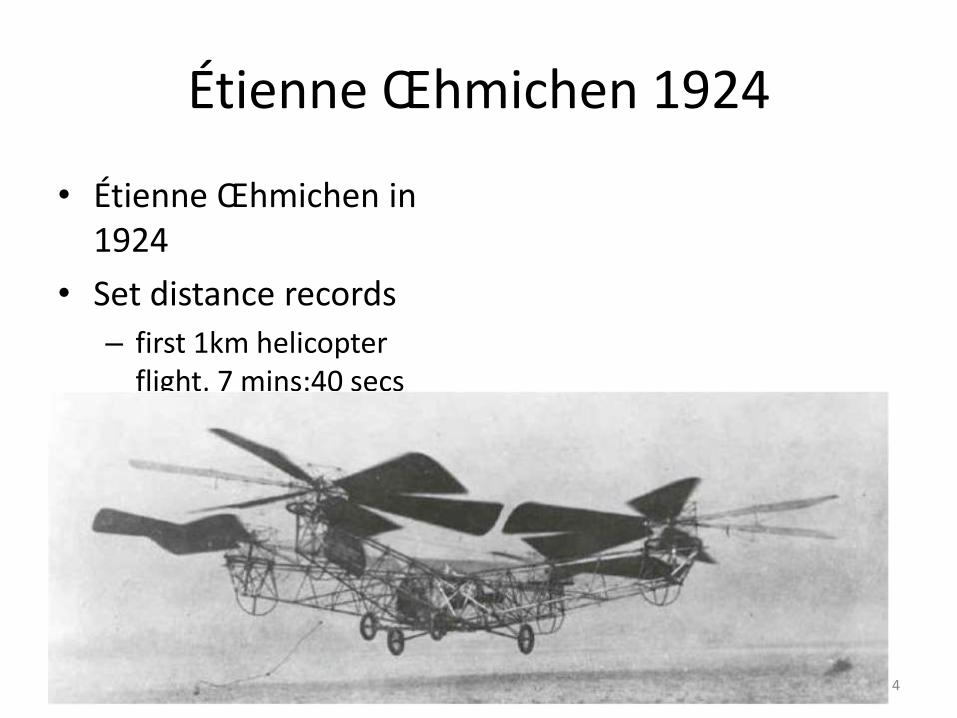
Étienne Œhmichen 1924
• Étienne Œhmichen in 1924
• Set distance records
– first 1km helicopter flight, 7 mins:40 secs
4

UAS Categories
• Fixed wing
– Better range
– Better performance
• Rotary wing
– higher degree of freedom
– low speed flying
– stationary flights
– indoor usage
5

Quadcopter
• 4 rotors located at the ends of a cross structure – higher payload capacity
– Maneuverability (e.g. traversing an environment with many obstacles, or landing in small areas)
• Controlled by varying the speeds of each rotor – Vertical Take Off and Landing (VTOL)
– hovering capability
– slow precise movements
– . There are also definite advantages to having a four rotor based propulsion system, such as a
6

Quadcopter Attitude Control
Mx = Motor direction Tx = Thrust force direction f = front l = left r = right b = back
7

Quadcopter Attitude Control
• Vary rotation speed of each motor
• Front Rotor (Mf) and Back Rotor (Mb) pair rotates in a clockwise direction
• Right Rotor (Mr) and Left Rotor (Ml) pair rotates in a counter-clockwise direction
– Configuration to balance the drag created by each of the spinning rotor pairs
8

Four Maneuvers
9

Four Maneuvers
• Roll Angle: • Change relative speed of the right and left rotors
• Pitch Angle • Change relative speed of the front and back rotors
• Yaw Angle • Change speed of clockwise rotating pair and counter-
clockwise rotating pair
• Vertical • Increasing or decreasing the speeds of all four rotors
simultaneously controls the collective thrust
10

Reference Frames
Inertial Frame = earth-based origin at launch location Body frame = CoG of vehicle aligned along frame Vehicle Frame = earth-based origin at CoG of Vehicle aligned with Inertial axes
11

Reference Frames
• Inertial – earth-fixed coordinate system – origin located on the ground (e.g. base station) – Convention:
• x-axis points towards the north • y-axis points towards the east • z-axis points towards the center of the earth.
• Body – origin located at the center of gravity (COG) of the quadrotor – axes aligned with the quadrotor structure
• x-axis is along the arm with front motor • y-axis is along the arm with right motor • z-axis cross product of x and y
• Vehicle – inertial frame with the origin located at the COG of the quadrotor – Vehicle frame has two variations, Fφ and Fθ
• Fφ is the vehicle frame – Fv, rotated about its z-axis by an angle ψ so that and are aligned with and , respectively.
• Fθ is frame Fφ rotated about its y-axis, , by a pitching angle, θ, such that x and y are aligned with and xb and zb
12

Transforming Reference Frames
• Translation and rotation matrices are used to transform one coordinate reference frame into another desired frame of reference
– Transformation from Fi to Fv provides the displacement vector from the origin of the Inertial frame to the center of gravity (COG) of the quadrotor Vehicle
– Transformation from Fv to Fb is rotational in nature the roll, pitch and yaw angles.
13

Quadrotor Kinematics
• Quadrotor Position fro Frame F
PTF = [px, py, -pz]
• Quadrotor Orientation for Frame F
ΩTF = [Φ, θ, Ψ]
• Quadrotor Speed
14
px
py
-pz
Fi
=
px
py
pz
Fv
=
px
py
pz
Fb
RFbFv
T
RFbFv
T = Translational matrix v b

Quadrotor Dynamics (Vertical Axis Only)
Total Thrust = Thrust front motor + Thrust back motor + Thrust left motor + Thrust right motor Weight (N) = mass (Kg) * gravitational constant (m/s2) = 9.8 Drag (N) = 0.5 * ρ * V2 * CD * Surface Area
15
Weight
Drag
Forces on Quadcopter (in body vertical axis)

Quadrotor Dynamics: Takeoff to Hover
ma = Σ F Hover az = 0, ax = ay = 0 Sum forces in Body Z axis 0 = T – W 0 = T – mg T = mg Thrust required to hover = thrust to overcome weight
Vertical Takeoff (i.e. stationary to climb velocity az > 0, ax = ay = 0 Sum forces in Body Z axis maz = T – W - D maz = T – mg - D T = mg + maz + D Thrust required to takeoff = thrust to overcome weight + thrust to overcome inertia + thrust to overcome Drag Drag = 0.5 ρ V2 CD Surface Area
16
Quadrotor Dynamics: Takeoff to Hover
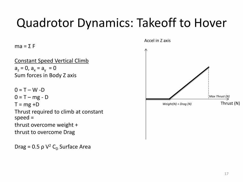
ma = Σ F Constant Speed Vertical Climb az = 0, ax = ay = 0 Sum forces in Body Z axis 0 = T – W -D 0 = T – mg - D T = mg +D Thrust required to climb at constant speed = thrust overcome weight + thrust to overcome Drag Drag = 0.5 ρ V2 CD Surface Area
17
Thrust (N)
Accel in Z axis
Max Thrust (N)
Weight(N) + Drag (N)
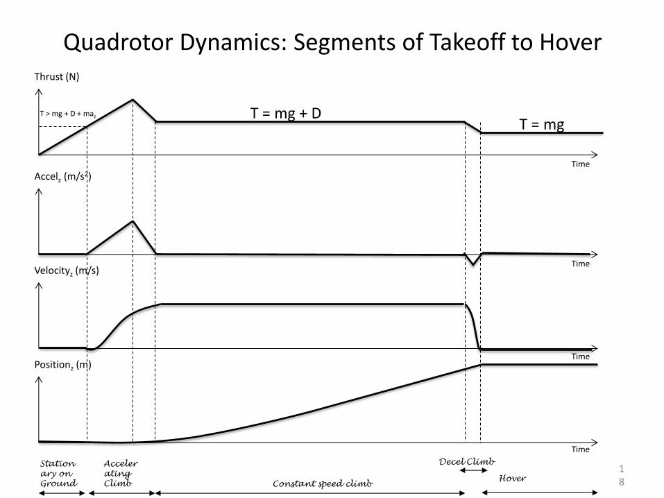
Quadrotor Dynamics: Segments of Takeoff to Hover
18
Thrust (N)
Accelz (m/s2)
Velocityz (m/s)
Positionz (m)
T = mg + D T > mg + D + maz
T = mg
Station
ary on
Ground
Acceler
ating
Climb Constant speed climb Hover
Decel Climb
Time
Time
Time
Time
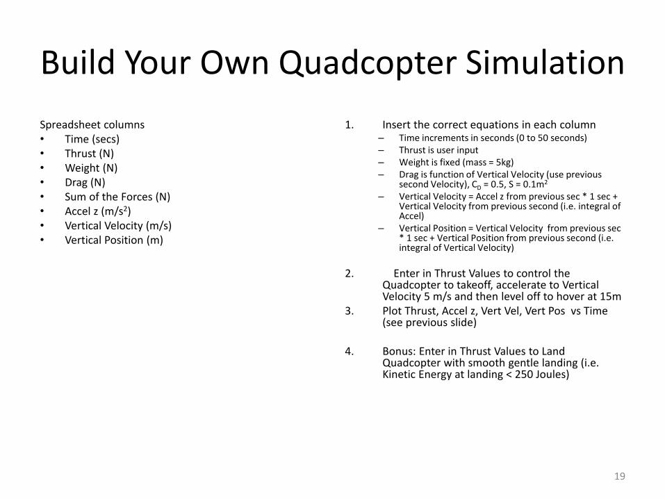
Build Your Own Quadcopter Simulation
Spreadsheet columns • Time (secs) • Thrust (N) • Weight (N) • Drag (N) • Sum of the Forces (N) • Accel z (m/s2) • Vertical Velocity (m/s) • Vertical Position (m)
1. Insert the correct equations in each column – Time increments in seconds (0 to 50 seconds) – Thrust is user input – Weight is fixed (mass = 5kg) – Drag is function of Vertical Velocity (use previous
second Velocity), CD = 0.5, S = 0.1m2 – Vertical Velocity = Accel z from previous sec * 1 sec +
Vertical Velocity from previous second (i.e. integral of Accel)
– Vertical Position = Vertical Velocity from previous sec * 1 sec + Vertical Position from previous second (i.e. integral of Vertical Velocity)
2. Enter in Thrust Values to control the Quadcopter to takeoff, accelerate to Vertical Velocity 5 m/s and then level off to hover at 15m
3. Plot Thrust, Accel z, Vert Vel, Vert Pos vs Time (see previous slide)
4. Bonus: Enter in Thrust Values to Land Quadcopter with smooth gentle landing (i.e. Kinetic Energy at landing < 250 Joules)
19

How to Move Forwards
20
T = mg Tf
Tb
Tz = mg
Tx = Dx +max
Hover Thrust is Vertical = Weight
Pitch Forward Thrust is tilted forward Vertical Thrust = Weight
Accelerate Forward Vertical Thrust = Weight Horizontal Thrust = thrust to overcome horizontal inertia + horizontal Drag

How to Pitch Forward
• Pitching Torque
Τθ = l (Tf-Tb)
l = length of boom (m)
To pitch forward
Tb > Tf
21
This diagram shows pitching backwards