quad cities unit 2, issuance of amendment 9, authorizing
TRANSCRIPT

PR 2 1 1975
Docket No. 50-265
Commonwealth Edison Company ATTN: Mr. J. S. Abel
Nuclear Licensing Administrator Boiling Water Reactors
P. 0. Box 767 Chicago, Illinois 60690
Gentlemen:
DISTRIBUTION Docket NRC PDR Local PDR ORB #2 Reading Attorney, OELD OI&E (3) NDube BJones (4) JMMcGough JSaltzman
- RMDiggs RReid RMDiggs DLZiemann SKari WOMiller BScharf (15)
TJCarter PCollins SVarga CHebron ACRS (14) JRBuchanan TBAbernathy 4)
"The Comrtssion has issued the enclosed Amendment No. 9 to Facility Licensu:DPR-30 for the Quad Cities Station Unit 2. This amendment includes Change No. 24 to the Technical Specifications and is in response to your request dated December 13, 1974, and supplements thereto dated December 20, 1974, February 20, 1975, February 27, 1975, and March 27, 1975.
This amendment authorizes operation with 8x8 fuel assemblies, replacement of a relief valve with a relief/safety valve and changes to the reactor vessel relief and safety valve setpoints. However, operation of the reactor is not authorized pending completion of our review of your analysis of emergency core cooling system performance submittal in accordance with the ABC Order for Modification issued December 27, 1974.
Copies of the related Safety Evaluation and the Federal Register Notice
are also enclosed.
Sincerely,
Original lgned by
Dennis L. Ziemann, Chief Operating Reactors Branch #2 Division of Reactor Licensing, (I
Enclosures: 1. Amendment No. 9
w/Change No. 24 2. Safety Evaluation 3. Federal Register Notice
cc w/enclosures: See next page
Form AEC-318 (Rev. 9-53) AECM 0240
It
V
* U. $: GOVERNMENT PRINTI;G
Commonwealth Edison Company - 2 - APR 2 1 1975
cc w/enclosures: Mr. Charles Whitmore President and Chairman Iowa-Illinois Gas and
Electric Company 206 East Second Avenue Davenport, Iowa 52801
John W. Rowe, Esquire Isham, Lincoln & Beale Counselors at Law One First National Plaza Chicago, Illinois 60670
Anthony Z. Roisman, Esquire Berlin, Roisman and Kessler 1712 N Street, N. W. Washington, D. C. 20036
Moline Public Library 504 - 17th Street Moline, Illinois 61265
Mr. Robert W. Watts, Chairman Rock Island County Board of
Supervisors Rock Island County Courthouse Rock Island, Illinois 61201
cc w/enclosures and cy of CECO filings dtd. 2/20/75, 2/27/75 and 3/27/75,, 3)4h f•;
Mr. Leroy Stratton Bureau of Radiological Health Illinois Department of Public Health Springfield, Illinois 62706
Mr. Gary Williams Federal Activities Branch Environmental Protection Agency 230 South Dearborn Street Chicago, Illinois 60604
Mr. Ed Vest Environmental Protection Agency 1735 Baltimore Avenue Kansas City, Missouri 64108

COMMONWEALMt EDISON COMPANY AND
IOWA-ILLINOIS GAS AND ELECTRIC COMPANY
DOCKET NO. 50-265
J•UAD CITIES NUCLEAR M.%0,%I-' STATION UNIT 2
AMENDMENT TO FACILITY OPERATING LICENSE
Amendment No. 9 License No. DPR-30
I. The Nuclear Regulatory Commission (the Commission) has found that:
A. 1he application for amendment by Commonwealth Edison Company (the licensee) dated December 13, 1974, and supplements dated December 20, 1974, February 20 and 27, 1975, and March 27, 1975, comply with the standards and requirements of the Atomic Energy Act of 1954, as amended (the Act), and the Commission's rules and regulations set forth in 10 CFR Chapter I;
B. The facility will operate in conformity with the application, the provisions of the Act, and the rules and regulations of the Commission;
C. There is reasonable assurance (i) that the activities authorized by this amendment can be conducted without endangering the health and safety-of the public, and (ii) that such activities will be conducted in compliance with the Commission's regulations; and
D. The issuance of this amendment will not be inimical to the common defense and security or to the health and safety of the public.
2. Accordingly, the license is amended by a change to the Technical Specifications as indicated in the attachment to this license amendment and Paragraphs 3.B and 3.C of Facility License No. DPR-30 are hereby amended to read as follows:
OFFICEO"
SURNAME*•
DATE)r ( .............................................. .............................................. .............................................. .............................................. ............................................. .......................... ...........
Formn AEC-318 (Rev. 9-53) AECM 0240 U. 92R;GOVERNMENT PRINTING OFFICE|g 1974-526-166

- 2 -
B. Technical Specifications
The Technical Specifications contained in Appendices A and B, as revised, are hereby incorporated in the license. The licensee shall operate the facility in accordance with the Technical Specifications, as revised by issued changes thereto through Change No. 24.
C. Restrictions
Operation of the reactor is not authorized beyond the point in the fuel cycle at which the reactivity insertion rate during a scram is less than that of Curve B on Figure 1 of "Dresden Station Special Report 29, Supplement B" dated March 29, 1974.
3. This license amendment is effective as of the date of its issuance.
FOR THE NUCLEAR REGUkTORY COMMISSION Oriýina- oiqnid by A.Giambusso
A. Giambusso, Director Division of Reactor Licensing Office of Nuclear Reactor Regulation
AttachmentChange No. 24 to the
Technical Specifications
Date of Issuance: APR 2.i 1975
OFFICE,)0
SURNAME*
D A T E ýI'* ............................................................................................. ............................................. ............................................. ........................................... . . . .
Form AEC-318 (Rev. 9-53) A.CM 0240 U. 8; GOVERNMENT PRINTING OFFICES 1274-526-166
ATTACHMENT TO LICENSE AMENDMENT NO. 9
CHANGE NO. 24 TO THE TECHNICAL SPECIFICATIONS
FACILITY OPERATING LICENSE NO. DPR-30
DOCKET NO. 50-26S
Delete pages 22, 24, 2S, 26, 7S, 76, 83, 92, 100 and 119 from the
Technical Specifications and insert the attached revised pages bearing
the same numbers. The changed areas on the revised pages are shown by
a marginal line.
OFFICE 30 S............. I.............................. .............................................. ............................................. ............... I ............................. . .............................................. ......................................
SURNAMEýN"
DATE-31 e ................................... .......... ............. ................................ .............................................. ..................................................................................................................................
Form AEC-318 (Rev. 9-53) A.ECM 0240 * U. S. GOVERNMENT PRINTING OFFICIEt 1974-526-106

2.1 Limiting Safety System Setting Bases (cont'd)
to give protection against rapid reactor depressurization and the resulting rapid cooldown of the vessel. Advantage was taken of tho scram feature in the run mode which occurs when the main steam line isolation valves are closed, to provide for reactor shutdown so that high power operation at low reactor pressures does not occur, thus providing protection for the fuel cladding integrity safety limit. Operation of the reactor at pressures lower than 850 psig requires that the reactor mode switch be in the startup position where protection of the fuel cladding integrity safety limit is provided by the IRM and APRM high neutron flux scrams. Thus, the combination of main steam line low pressure isolation and isolation valve closure scram in the run mode assures the availability of neutron flux scram protection over the entire range of applicability of the fuel cladding integrity safety limit. In addition, the isolation valve closure scram in the run mode anticipates the pressure and flux transients which occur during normal or inadvertent isolation valve closure. With the scrams set at 10% valve closure in the run mode there is no increase in neutron flux.
I. Turbine EHC Control Fluid Low Pressure Scram The turbine EHC control system operates using high pressure oil. There are several points in this oil system where a loss of oil pressure could result in a fast closure of the turbine control valves. This fast closure of the turbine control valves is not protected by the turbine control valve fast closure scram since failure of the oil system would not result in the fast closure solenoid valves being actuated. For a
turbine control valve fast closure, the core would be protected by the APRM and high reactor pressure scrams. However, to provide the same margins as provided for the generator load rejection on fast closure of the turbine control valves, a scram has been added to the reactor protection system which senses failure of control oil pressure to the turbine control system. This is an anticipatory scram and results in reactor shutdown before any significant increase in neutron flux occurs. The transient response is very similar to that resulting from the turbine control valve fast closure scram. The scram setpoint of 900 psig is set high enough to provide the necessary anticipatory function and low enough to minimize the number of spurious scrams. Normal operating pressure for this system is 1250 psig. Finally the control valves will not start until the fluid pressure is 600 psig. Therefore, the scram occurs well before valve closure begins.
J. Condenser Low Vacuum Scram - Loss of condenser vacuum occurs when the condenser can no longer handle the heat input. Loss of condenser vacuum initiates a closure of the turbine stop valves and turbine bypass valves which eliminates the heat input to the condenser. Closure of the turbine stop and bypass valves causes a pressure transient, neutron flux rise, and an increase in surface heat flux. To prevent the clad safety limit from being exceeded if this occurs, a reactor scram occurs on turbine stop valve closure in the run mode. The turbine stop valve closure scram function alone is adequate to prevent the clad safety limit from being
1 24
22

1.2 SAFETY LIMIT 2.2 L!,•,IITIING SAFETY SYSTEM SETTING
1.2 REACTOR COOLAN",T SYSTEM
Applicability:
Applies to limits oti reactor coolant
system pressure.
)
Objective:
To establish a limit below which the
integrity of the reactor coolant system is not threatened due to an overpressure condition.
Specification:
The reactor coolant system pressure shall not exceed 1325 psig at any time when irradiated fuel is present in the reactor vessel.
2.2 REACTOR COOLANT SYSTEM
Applicability:
Applies to trip settings of the instruments and devices which are provided to prevent
the reactor system safety limits from being exceeded.
Oblective:
To define the level of the process variables at which automatic protective action is
initiated to prevent the safety limits from
being exceeded.
Snecification:
A. Reactor coolant high pressure scram shall be <1060 psig.
B. Primary system safety valve Nominal
settings shall be as follows:
1 valve 2 valves 2 valves 4 valves
at 1125 psig* at 1240 psig at 1250 psig at 1260 psig
The allowable setpoint error for each valve shall be +1%.
*Target Rock combination safety/relief malve
:24
24
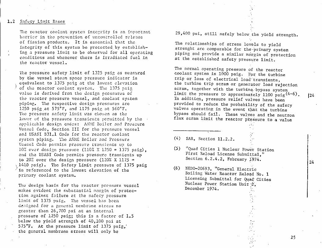
1.2 Safety Limit Bases
The reactor coolant system integrity is an iniportant barrier in the prevention of uncontrolled release of fission products, It is essential that the integrity of this system be protected by establishing a pressure limit to be observed for all operating conditions and whenever there is irradiated fuel in the reactor vessel.
The pressure safety limit of 1325 psig as measured by the vessel steam space pressure indicator is equivalent to 1375 psig at the lowest elevation
) of the reactor coolant system, Tl•e 1375 psig value is derived from the design pressures of the reactor pressure vessel, and coolant system piping. The respective design pressures are 1250 psig at 575°F, and 1175 psig at 560'F. The pressure safety limit was chosen as the lower of the pressure transients permitted by the applicable design codes: ASNE Boiler and Pressure Vessel Code, Section III for the pressure vessel and USASI B31.1 Code for the reactor coolant system piping. TChe ASME Boiler and Pressure Vessel Code permits pressure transients up to 10% over design pressure (110% X 1250 = 1375 psig), and the USASI Code permits pressure transients up to 20% over the design pressure (120% X 1175 = 1410 psig). The Safety Limit pressure of 1375 psig is referenced to the lowest elevation of the primary coolant system.
The design basis for the reactor pressure vessel makes evident the substantial margin of protection against failure at the safety pressure limit of 1375 psig. The vessel has been dc-;igned for a general membrane stress no greater than 26,700 psi at an internal pressure of 1250 psig; this is a factor of 1.5 below the yield strength of 40,100 psi at 575'F. At the pressure limit of 1375 psig, the general membrane stress will only be
29,400 psi, still safely below the yield strength.
The relationships of stress levels to yield strenght are comparable for the.primary system piping snd provide a similar margin of protection at the established safety pressure limit.
The normal operating pressure of the reactor coolant system is 1000 psig. For the turbine trip or loss of electrical load transients, the turbine trip scram or generator load rejection scram, together with the turbine. bypass system limit the pressure to approximately 1100 psig( 4 -6). In addition, pressure relief valves have been provided to reduce the probability of the safety valves operating in the event that the turbine bypass should fail. These valves and the neutron flux scram limit the reactor pr.essure to a value
(4) SAR, Section 11.2.2.
(5) "Quad Cities 1 Nuclear Power Station First Reload License Submittal," Section 6.2.4.2, February i:974.
(6) NEDO-20693, "General Electric Boiling Water Reactor Reloa4 No. 1 Licensing Submittal for Quad Cities Nuclear Power Station Unit 22, December 1974.
25
124
24

1.2 Safety Limit Bases (Cont'd)
Reactor pressure is continuously monitored in the control room during operation on a 1500 psi full scale pressure recorder.
2.2 Limiting Safety System Setting Bases
In compliance with Section III of the ASME Code, the safety valves must be set to open at no higher than 103% of design pressure, and they must limit the reactor pressure to no more than 110% of design pressure. Both the high pressure scram and safety valve actuation are required to prevent overpressurizing the reactor pressure vessel and thus exceeding the pressure safety limit. The pressure scram is actually a backup protection to the high flux scram which was analyzed( 9 ) in Section 4.4.3 of the SAR, and reexamined for Unit 1 fuel cycle 2 in "Dresden Station Special Report No. 29 Supplement B." If the high flux scram were to fail during a maximum pressure transient (also assuming failure of the turbine stop valve closure scram, failure of the bypass system to actuate and failure of the relief valves to open), the pressure would rise rapidly due to void reduction in the core. A high pressure scram would occur at 1060 psig.
actuation provide adequate margin below thepeak allowable vessel pressure of 1375 psig.
Unit' 2
The pressure at the botton of the vessel is about 1158 psig when the'first safety valve opens and about 1314 psig when the last valve' opens. Both values are clearly within the code requirements.
Vessel dome pressure reaches about 1292 psig" with the peak at the bottom of the vessel near 1322 psig. Therefore, the neutron flux scram.and safety valve actuation provide adequate margin below the peak allowable vessel pressure of 1375 psig.
Unit I
The pressure at the botton of the vessel is about 1163 psig when the first safety valve opens and about 1290 psig when the last valve opens. Both valves are clearly within code requirements. Vessel dome pressure reaches less than 1277 psig with a peak at the bottom of vessel less than 1301 psig. Therefore, the pressure scram and safety valve
(9) "Quad Cities 1 Nuclear Power Station First Reload License Submittal", Section 6.2.4.2, February 1974.
26
)24

3.3 LIMITING CONDITION FOR OPERATION 4.3 SURVEILLANCE REQUIREMENT
5. During operation with limiting control rod patterns, as determined by the nuclear engineer, either:
a. Both TBM channels shall be operable; or
b. Control rod withdrawal shall be blocked; or
c. The operating power level shall be limited so that the MCIFR will remain above 1.0 assuming a single error that results in complete withdrawal of any single operable control rod.
C. Scram Insertion Times
1. The average scram insertion time, based on the de-energization of the scram pilot valve solenoids at time zero, of all operable control rods in the reactor power operati'on
Ž condition shall be no greater than:
% Inserted From Fully Withdrawn
5 20 50, 90
Avg. Scram insertion Times (sec)
0.375 0.900 2.00 3.50
C.
75
24 1
5. mien a limiting control rod pattern
exists, an instrument functional test
of the RBM shall be perf'amed prior to
withdrawal of the designated rod(s) and daily thereafter.
Scram Insertion Times
1. Aftcr refueling outag~e nd' prior
to operation above 30/ p6ower with reactor pressure above 80 0 :psig, all control rods shall ...subject
to scram-time measurement§ from the fully withdrawnposition. The scram times shall be:,.easured
without reliance on the qontrol rod
drive pumps.

3.3 LIMITING CONDITION FOR OPERATION 4.3 SURVEILLANCE REQUIRE:,E,,.•,
The average of the scram insertion times for
the three fastest control rods of all groups
of four control rods in a two by two array shall be no greater than:
% Inserted From Fully Withdrawn
5 20 50 90
Avg. Scram Insertion Times (see)
0.398 0.954 2.12 3.80
2. The maximum scram insertion time for90% insertion of any operable control rods
shall not exceed 7.00 seconds.
3. If Specification 3.3.C.1 cannot be met, the reactor shall not be made supercritical; if operating, the reactor shall be shut down ii,,zmediately upon determination that average scram time is deficient.
'4. If Specification 3.3.C.2 cannot be met,
the deficient control rod shall be considered inoperable, fully inserted into the core, and electrically disarmed.
N,
2. Following a controlled :shutdown of the reoýctor, but not more fLiquently than 16 weeks nor less frequently than 32 week intervals, 507 of:. the control rod drives' in each quadranplt 6f the reactor core shall be measured6for scram times specified in SpecificatC'n 3.3.Co All control rod drives shall. have experienced scram test measurementsi:"each year. Wlhenever all of the cont`rbl rod drives scram times have been me asured, an evaluation shall be made to pPvide reasonable assurance that proper cQntrol rod drives performance is being mi2.r1tained. The
results of measurements.perforned on the control rod drives sha4l`be.submitted in the semiannual opera:fing report to the NRC.
76
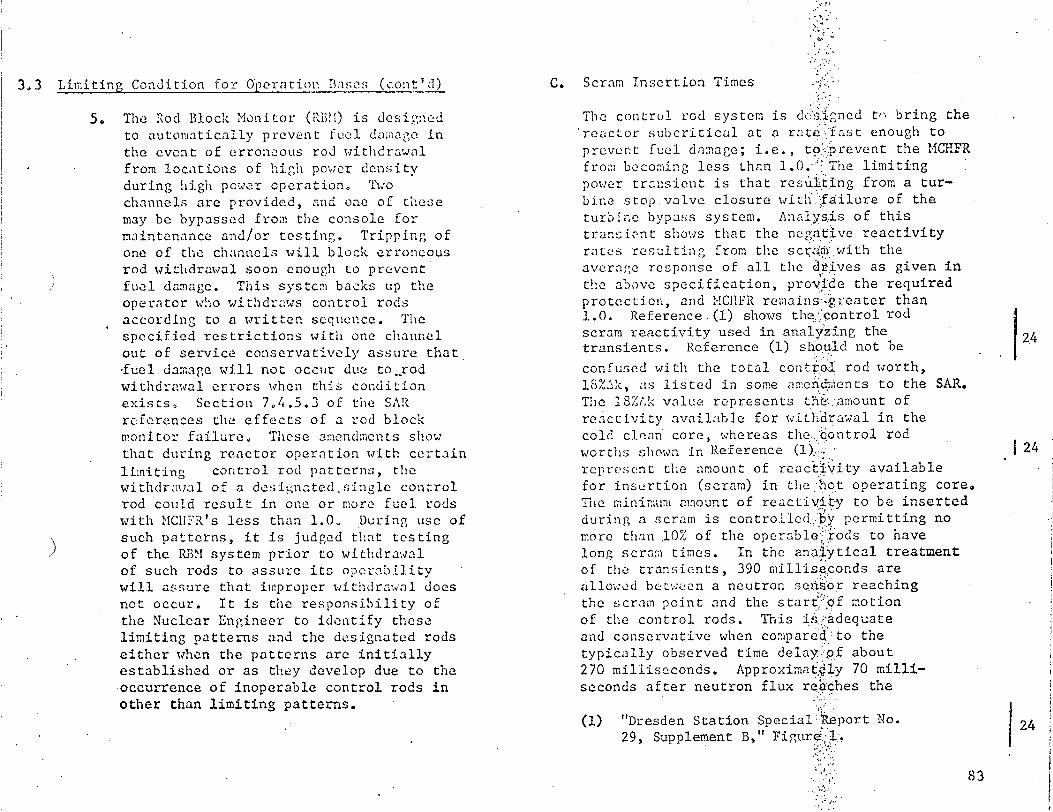
3.3 Limiting Condition for Operation Bnases (cont'd)
5. The Rod Block Monitor (RB2M) is desi,"ned to automatically prevent fuel dam;iage in
the event of erroneous rod withdrawal
from locations of high power density
during high power operation. 'Awo channels are provided, and one of these
may be bypassed from the console for
maintenance and/or testing. Tripping of
one of the channels will block erroneous
rod withdrawal soon enough to prevent fuel damage. This system backs up the
operator who withdraws control rods
according to a written sequence. The
specified restrictions with one channel
out of service conservatively assure that
,fuel damage will not occur due to..rod
withdrawal errors when this condition
exists, Section 7.4.5.3 of the SAR
references the effects of a rod block
monitor failure, These amendments show
that during reactor operation with certain
limiting control rod patterns, the withdraweal of a designated.siagle control
rod could result in one or more fuel rods
with MCHFR's less than 1.0. During use of
such patterns, it is judged that testing
of the E1BM system prior to withdrawal
of such rods to assure its operability
will assure that improper withdrawal does
not occur. It is the responsibility of
the Nuclear Engineer to identify these
limiting patterns and the designated rods
either when the patterns are initially established or as they develop due to the
occurrence of inoperable control rods in
other than limiting patterns.
C. Scram Insertion Times
Tihe control rod system is dc.-'Mgned tn bring the reactor subcritical at a rateafast enough to prevent fuel damage; i.e., to :-prevent the MCHFR from becoming less than 1.0. The limiting power transient is that resUiting from a turbine stop.valve closure wita failure of the turbine bypass system. Analysbis of this transient shows that the negwtive reactivity rates resulting from the scaihv with the average response of all the drives as given in the above specification, provide the required protection, and MCHFR remains<g reater than 1.0. Reference.(l) shows the' control rod scram reactivity used in anaiyýzing the transients. Reference (1) should not be
confused with the total cont.ro, rod worth, l3%.1,k, as listed in some ameni d&ents to the SAR. The t8%A• value represents the .,amount of reactivity available for wit h-drawal in the cold clealn core, whereas the &ontrol rod worths shown in Reference ().i. represent the amount of reactivity available for insertion (scram) in the hot operating core. The minimum amount of reactivi.ty to be inserted during a scram is contro.Lled.by permitting no more than 10% of the operable'i.ods to have long scram times. In the analytical treatment of the transients, 390 milliseconds are allowed betw.den a neutron sensor reaching the scram point and the start 'I:of motion of the control rods. This i.,;,adequate and conservative when compared:to the typically observed time delayfp.ýjof about 270 milliseconds. Approximat.ly 70 milliseconds after neutron flux re,4ches the
(1) "Dresden Station Special: Ieport No. 29, Supplement B," Figure .
83
)
f24
1 24
24
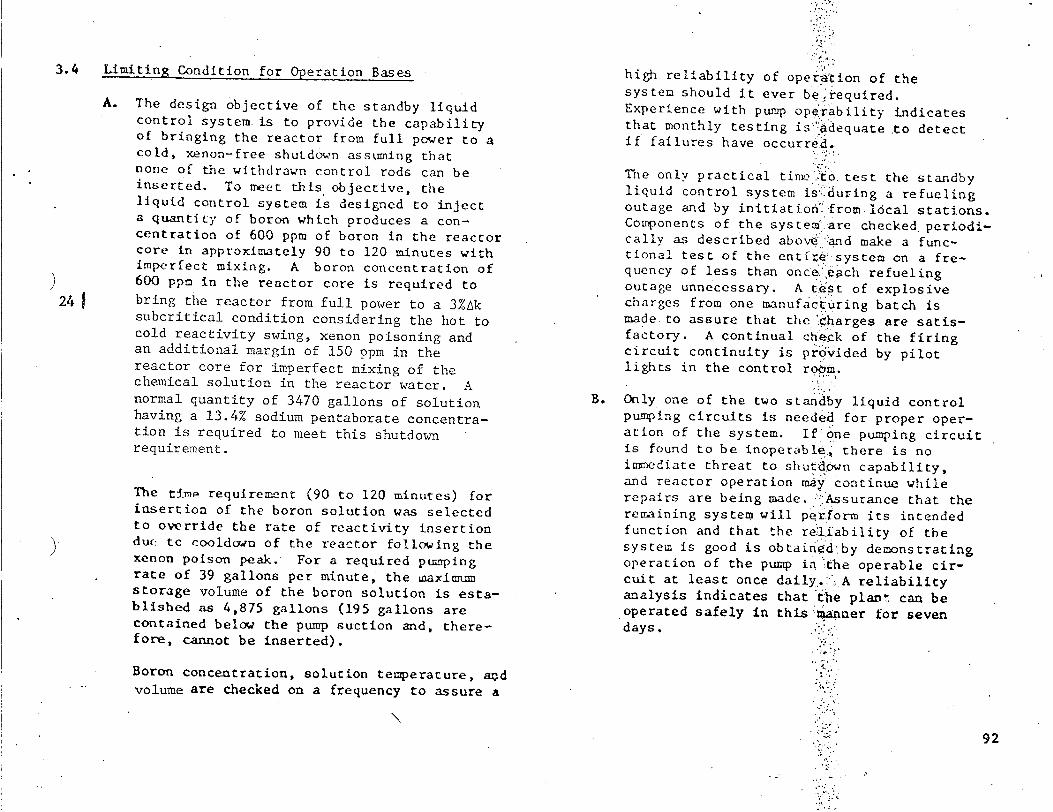
3.4 Limiting Condition for Operation Bases
A. The design objective of the standby liquid control system is to provide the capability of bringing the reactor from full power to a cold, xenon-free shutdown assuming that none of the withdrawn control rods can be inserted. To meet tlhis objective, the liquid control system is designed to inject a quantity of boron which produces a concentration of 600 ppm of boron in the reactor core in approximately 90 to 120 minutes with imperfect mixing. A boron concentration of 600 ppm in the reactor core is required to bring the reactor from full power to a 3%Ak subcritical condition considering the hot to cold reactivity swing, xenon poisoning and an additional margin of 150 ppm in the reactor core for imperfect mixing of the chemical solution in the reactor water. A normal quantity of 3470 gallons of solution having a 13.4% sodium pentaborate concentration is required to meet this shutdown requirement.
The tim. requiremnt (90 to 120 minutes) for insertion of the boron solution was selected to override the rate of reactivity insertion dut: tc cooldown of the reactor following the xenon poison peak. For a required pumping rate of 39 gallons per minute, the maximum storage volume of the boron solution is established as 4,875 gallons (195 gallons are contained below the pump suction and, therefore, cannot be inserted).
Boron concentration, solution temperature, aj~d volume are checked on a frequency to assure a
high reliability of operai'tion of the system should it ever be required. Experience with pump ope"rability indicates that monthly testing is. adequate to detect if failures have occurred.
The only practical tim `,to. test the standby liquid control system isi:Jduring a refueling outage and by initiationh from l6cal stations. Coironents of the system .are checked periodically as described above <and make a functional test of the entfre6 system on a frequency of less than once.ýeach refueling outage unnecessary. A tlest of explosive charges from one manufact uring batch is made. to assure that the :harges are satisfactory. A continual check of the firing circuit continuity is prdivided by pilot lights in the control room.
B. Only one of the two standby liquid control pumping circuits is needed for proper operation of the system. If-one pumping circuit is found to be inoperable.* there is no irn~ediate threat to shutd.own capability, and reactor operation mayý continue while repairs are being made. i:Assurance that the remaining system will perform its intended function and that the re:liability of the system is good is obtain'd-by demonstrating operation of the pump in 'the operable circuit at least once dailyi. A reliability analysis indicates that the plawt can be
.operated safely in this'manner for seven days.
92
24

3.5 LIMITING CONDITION FOR OPMr%\TION
D. Automatic Pressure Relief Subsystems
1. The Automatic Pressure Relief Subsystem
,-:all be operable whenever the reactor
) pressure is greater than 90 psig, ir
radiated fuel is in the reactor vessel
and prior to reactor startup from a
'Cold Condition.
2. From and after the date that one of the five relief valves of the automatic pressure relief subsystem is made or
found to be inoperable when the
reactor is pressurized above 90 psig
with irradiated fuel in the reactor
vessel, continued reactor operation
is permissible only during the succeeding
thirty days unless repairs are made
and provided that during such time
the HPCI subsystem is operable.
100
17 & 24
D. Automatic Pressure Relief Subsystems
Surveillance of the automatic pres-s re relief
subsystems shall be performed as Follows:
1. During each operating cycle t.e following
shall be performed:
a. A simulated automatic injý.iation
which opens all pilot val`Vs, and
b. With the reactor at low pressure
each relief valve shall bi.:.manually
opened until thermocoup.es. .down
stream of the valve indicate fluid
is flowing from the valve`,.:-.
c. A logic system functional- Ltest
shall be performed each refueling outage.
2. .hen it is determined that one::.relief
valve of the automatic pressure relief
subsystem is inoperable, the HPCI shall
be demonstrated to be operabld'eimmediately and weekly thereafter.
4.5 SURIVE!LLA=C REQUTREMET-.i

3.6 LIMITING CONDITION FOR OPERATION 4.6 SURVEILLANCE REQUIREMENT
Vn 4: t.nA Re1lef Valves E. Safety and Relief Valves
1. Prior to reactor startup for power operation
and during reactor power operating condi
tions and whenever the reactor coolant
pressure is greater than 90 psig and
temperature greater than 320 0 F, all
nine of the safety valves shall be
operable. The solenoid activated
pressure valves shall be operable as
required by Specification 3.5.D.
)
2. If Specification 3.6.E.1 is not met,
the reactor shall remain shutdown until
the condition is corrected or, if in
operation, an orderly shutdown shall be
initiated and the reactor coolant pressure
and temperature shall be below 90 psig
and 320*F within 24 hours.
A minimum of 1/2 of all safety valves shall be bench checked or replaced with a bench
checked valve each refueling outage. The
popping point of the safety valves shall be
set as follows:
Number of Valves
1 2 2 4
The allowable set point is +1%.
All relief valves shall pressure each refueling pressures shall be:
Number of Valves
2 2 2
Set-Point (2219)
1125* 1240 1250 1260
error for each valve
be checked for set outage. The set
Set Point (psig)
:1125" 1130 < 1135
*Target Rock combination safety/relief valve.
24
12
119
)
1

¾��
UNITED STATES
NUCLEAR REGULATORY COMMISSION WASHINGTON, D. C. 20555
SAFETY EVALUATION BY THE OFFICE OF NUCLEAR REACTOR REGULATION
SUPPORTING AMENDMENT NO. 9 TO FACILITY OPERATING LICENSE NO. DPR-30
(CHANGE NO. 24 TO THE TECHNICAL SPECIFICATIONS)
COMMONWEALTH EDISON COMPANY AND
IOWA-ILLINOIS GAS AND ELECTRIC COMPANY
eQUAD CITIES UNIT 2
DOCKET NO. 50-265
INTRODUCTION
By application dated December 13, 1974, Commonwealth Edison Company (CE) requested authorization to operate Quad Cities Unit 2 with reload fuel assemblies in the core. According to CE's plan, as many as 148 .8x8 reload fuel assemblies will replace an equal number of fuel assemblies presently in the core. In conjunctionwith the reload, it has been proposed that several areas of the Technical Specifications be changed and that certain modifications to the reactor be approved.
The following Technical Specification changes and plant modifications have
been proposed:
1. Reload with 8x8 fuel,
2. Replacement of a relief valve with a relief/safety valve and change of relief and safety valve setpoints,
3. Change of average power range monitor (APRM) and rod block monitor (RBM) trip settings to be discussed in the safety evaluation related to item 4 below,
%
4. Adoption of Technical Specification based on the new GEXL boiling transition correlation and
00o.LIoIO4
-2-
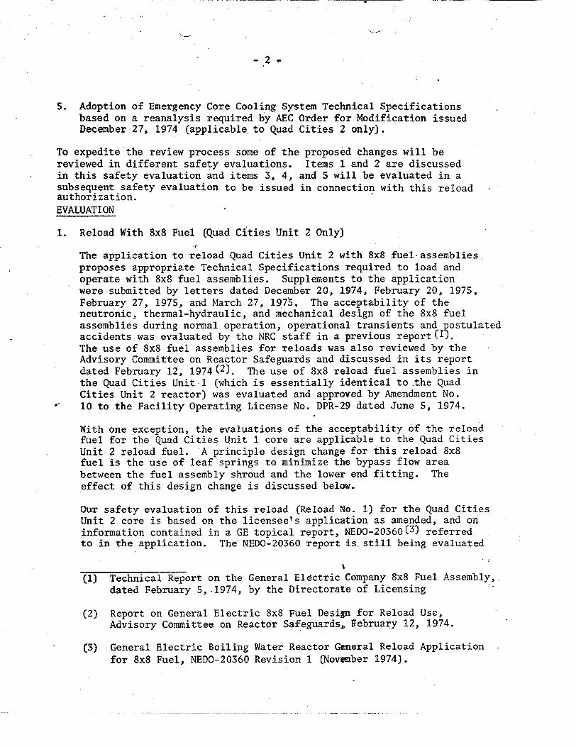
5. Adoption of Emergency Core Cooling System Technical Specifications based on a reanalysis required by AEC Order for Modification issued December 27, 1974 (applicable to Quad Cities 2 only).
To expedite the review process some of the proposed changes will be reviewed in different safety evaluations. Items 1 and 2 are discussed in this safety evaluation and items 3, 4, and 5 will be evaluated in a subsequent safety evaluation to be issued in connection with this reload authorization. EVALUATION
1. Reload With 8x8 Fuel (Quad Cities Unit 2 Only)
The application to reload Quad Cities Unit 2 with 8x8 fuel assemblies, proposes appropriate Technical Specifications required to load and operate with 8x8 fuel assemblies. Supplements to the application were submitted by letters dated December 20, 1974, February 20, 1975, February 27, 1975, and March 27, 1975, The acceptability of the neutronic, thermal-hydraulic, and mechanical design of the 8x8 fuel assemblies during normal operation, operational transients and postulated accidents was evaluated by the NRC staff in a previous report . The use of 8x8 fuel assemblies for reloads was also reviewed by the Advisory Committee on Reactor Safeguards and discussed in its report dated February 12, 1974(2). The use of 8x8 reload fuel assemblies in the Quad Cities Unit 1 (which is essentially identical to the Quad Cities Unit 2 reactor) was evaluated and approved by Amendment No. 10 to the Facility Operating License No. DPR-29 dated June 5, 1974.
With one exception, the evaluations of the acceptability of the reload fuel for the Quad Cities Unit 1 core are applicable to the Quad Cities Unit 2 reload fuel. A principle design change for this reload 8x8 fuel is the use of leaf springs to minimize the bypass flow area between the fuel assembly shroud and the lower end fitting. The effect of this design change is discussed below.
Our safety evaluation of this reload (Reload No. 1) for the Quad Cities Unit 2 core is based on the licensee's application as amended, and on information contained in a GE topical report, NEDO-20360( 3 ) referred to in the application. The NEDO-20360 report is still being evaluated
(1) Technical Report on the General Electric Company 8x8 Fuel Assembly, dated February 5,.1974, by the Directorate of Licensing
(2) Report on General Electric 8x8 Fuel Design for Reload Use, Advisory Committee on Reactor Safeguards,. February 12, 1974.
(3) General Electric Boiling Water Reactor General Reload Application for 8x8 Fuel, NEDO-20360 Revision 1 (November 1974).

- 3-
by the staff for use as a topical. Our use of that report in this
analysis was limited to considerations applicable to Quad Cities Unit
2 and does not imply acceptability of its use for other facilities.
Authority to load but not operate with Reload 1 fuel was approved by
Amendment No. 8, with Change No. 23, to Facility Operating License
No. DPR-30 dated February 13, 1975.
The reference Quad Cities Unit 2 Reload 1 consists of 576 initial
7x7-fuel assemblies and one hundred forty-eight 8x8 reload fuel
assemblies which are scatter loaded throughout the interior of the
core. Four fuel assemblies surrounding a control blade will contain
only one 8x8 reload fuel assembly. This loading scheme assures
that, in the core interior, the higher enrichment 8x8 reload fuel
assembly will be "paired" with three lower powered exposed 7x7 fuel
assemblies. No significant fuel loading asymmetries will exist.
The NRC staff has previously reviewed(1) the mechanical design
of the 8 x 8 reload fuel assemblies. In addition the 8 x 8
reload fuel assemblies for Quad Cities Unit 2 are of similar
design to the 8 x 8 fuel assemblies approved for use in Quad
Cities Unit 1 by Amendment No. 10 to Facility Operating
License No. DPR-29. Because Quad Cities Units 1 and 2 operate
at identical conditions and the fuels used are nearly identical,
the evaluation of mechanical design discussed in our safety evaluation
for Amendment No. 10 to Facility Operating License No. DPR-29 is
applicable to the 8x8 reload fuel assemblies for Quad Cities Unit 2.
The 8x8 fuel assemblies for Quad Cities Unit 2 are of similar design
and material to the 7x7 fuel assemblies which have successfully been
operated at Quad Cities Unit 2. Both the 8x8 and 7x7 fuel assemblies
will operate at the same pressure and temperature and the fluid
velocity and quality will be nearly identical and, therefore, the new 8x8
fuel assemblies are expected to exhibit the same operational charac
teristics as the previously operated 7x7 fuel assemblies.
Mechanical and operating parameters for the 8x8 assemblies are compared
with the 7x7 assemblies in Table 1. The smaller diameter rods, with
lower linear heat generation rate and larger cladding thickness/
diameter ratio for the 8x8 fuel design, result in increased engineering
safety margins when compared with the 7x7 fuel assemblies. The
maximum design linear power is significantly reduced for the
8x8 fuel. The reload fuel incorporates finger springs for
controlling moderator/coolant bypass flow at the interface

-4-
TABLE 1
COMPARISON OF PARAMETERS FOR 8X8 AND 7X7
ROD FUEL ASSEMBLY DESIGN
Pellet Outside Diameter (in.)
Rod Outside Diameter (in.)
Rod-to-Rod Pitch (in.)
Water-Fuel Ratio (cold)
U Bundle Weight (pounds)
Cladding Thickness (mils)
Active Fuel Length (in.)
Maximum Design Power (kw/ft)
7X7
0.477
0.563
0.738
2.53
412.8
37
144
17.5
8X8
0.416
0.493
0.640
2.60
404.6
34
144
13.4
. . . . . :.:. •.. .... • ,~~~~~~..•.• .i ...: ".:..'.-.:. -....... .. ...."...........-.. . - -:- .: .: .;.. : • . ,.;. ......,... .. .. •. . . .
. .. .- : .. .. - , .- . . . • , , . : . , . .. .. • ;. - .

- 5 -
lof the channel and fuel bundle lower tie plate. This device has performed satisfactorily in other reactors on more than 900 assemblies that have been inspected.
Four different U-235 enrichments are used in the reload fuel assemblies to reduce the local power peaking factor. In addition, gadoliniaurania pellets are used in four of the highest enrichment rods. Gadolina is a burnable poison and supplements the control rods in flattening the power distribution of the core. The use and performance of gadolinia - bearing fuel was evaluated by us for the initial core of Quad Cities 1 and 2 and found acceptable.
Fuel performance calculations that account for the effects of fuel densification have been performed with our approved version of the General Electric analytical model, GEGAP I1I(4,5) . The effects of fuel densification on the fuel rod will be that of increasing the stored energy, increasing the linear thermal output, and increasing the probability of local power spike from axial gaps. The primary effects of densification on the fuel rod mechanical design are manifested in calculations on fuel-clad gap conductance and cladding 1611aps- time. The approved analytical model incorporates time-dependent fuel densification, time-dependent gap closure and cladding creepdown for the calculation of gap conductance. Clad collapse has not been observed in RWR fuel rods and is calculated to occur at core residence times in excess of 5 years. The fuel residence time is expected to be approximately 4 years. Therefore, densification effects have been appropriately considered.
Accident induced loads and stresses have been calculated for both the 7x7 and 8x8 fuel assemblies using the same methods. The limiting accident loads result from a steam line break. The pressure difference following a steam line break are less than 10% greater than normal operating pressure differences. As in normal operation, the pressure differences in an 8x8 assembly following a steam line-break are S to 10% greater than in a 7x7 assembly. The loads following a steam line break are well below the allowable loads.
The reload 8x8 fuel design is currently in operation in Nine Mile Point, Pilgrim 1, Monticello, Dresden 2 and 3, Quad Cities 1 and Vermont Yankee. Post irradiation examination of these assemblies
(4) GEGAP-Il, "A Model for the Prediction of Pellet Clad Thermal Conductance in B1WR Fuel Pools," NEDO-20181, December 3, 1973, Supplement 1 (Proprietary)
I5) V. A. lie e, NRC Letter to I. S. Mi chell, "odif ed GE Model
CWRNME* 1 oU N A E .............................. ... .. .. .. .. .... .. .. ... .. .. .. .. ... .. .. ... .. .. .. .. .. .. .. .. ... .. .. .. .. .. .. .. .. ... .. .. .. .. .. .. .. ..... .... .... .. .. .... ... .. .. .. .. ...... .. ... .. .. .. .. .. .. .. .. .. DUR N A TM E * .} ....... .. . . . ........................................... .............................................. ............................................. ............................................ ............................................. ............... ....... .
DATE 9 C s; I 1
Porm AEC-318 (Rev. 9-53) AE]GM 0240 * u. a; GOV!RNME*NTr PRINTIlNG OPFICBt 1974-520-166
-6-
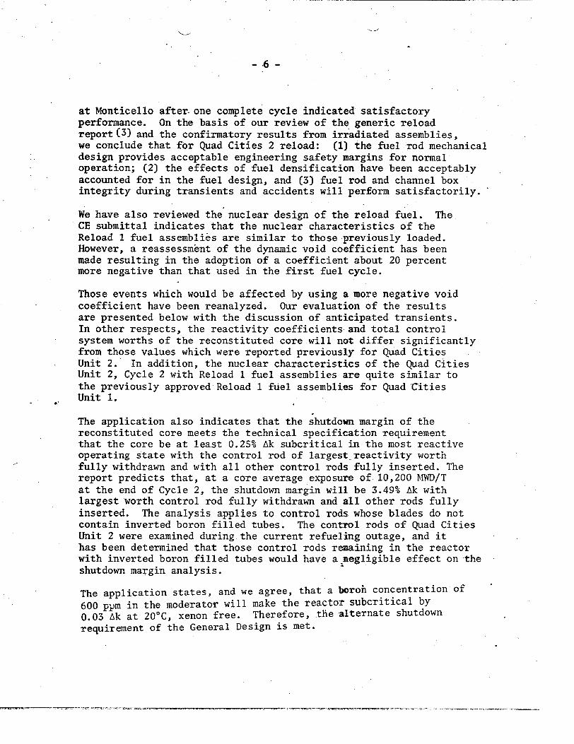
at Monticello after. one complete cycle indicated satisfactory performance. On the basis of our review of the generic reload report (3) and the confirmatory results from irradiated assemblies, we conclude that for Quad Cities 2 reload: (1) the fuel rod mechanical design provides acceptable engineering safety margins for normal operation; (2) the effects of fuel densification have been acceptably accounted for in the fuel design, and (3) fuel rod and channel box integrity during transients and accidents will perform satisfactorily.
We have also reviewed the nuclear design of the reload fuel. The CE submittal indicates that the nuclear characteristics of the Reload 1 fuel assemblies are similar to those previously loaded. However, a reassessment of the dynamic void coefficient has been made resulting in the adoption of a coefficient about 20 percent more negative than that used in the first fuel cycle.
Those events which would be affected by using a more negative void coefficient have been reanalyzed. Our evaluation of the results are presented below with the discussion of anticipated transients. In other respects, the reactivity coefficients and total control system worths of the reconstituted core will not differ significantly from those values which were reported previously for Quad Cities Unit 2. In addition, the nuclear characteristics of the Quad Cities Unit 2, Cycle 2 with Reload 1 fuel assemblies are quite similar to the previously approved Reload 1 fuel assemblies for Quad-Cities Unit 1.
The application also indicates that the shutdown margin of the reconstituted core meets the technical specification requirement that the core be at least 0.25% Ak subcritical in the most reactive operating state with the control rod of largest reactivity worth fully withdrawn and with all other control rods fully inserted. The report predicts that, at a core average exposure of 10,200 MWD/T at the end of Cycle 2, the shutdown margin will be 3.49% Ak with largest worth control rod fully withdrawn and all other rods fully inserted. The analysis applies to control rods whose blades do not contain inverted boron filled tubes. The control rods of Quad Cities Unit 2 were examined during the current refueling outage, and it has been determined that those control rods remaining in the reactor with inverted boron filled tubes would have a megligible effect on the shutdown margin analysis.
The application states, and we agree, that a boroh concentration of
600 ppm in the moderator will make the reactor subcritical by
0.03 Ak at 20 0 C, xenon free. Therefore, the alternate shutdown
requirement of the General Design is met.

-. 7 -
The basic criterion for the storage of fuel for Quad Cities Unit 2
is that keff, of the fuel as stored in the fuel pool is <0.90.
This is achieved if the uncontrolled infinite multiplication factor
of a single fuel assembly is less than 1.26 at 650 C. The 8x8 reload
fuel at both zero exposure and the peak reactivity point has an infinite
multiplication factor of <1.26, and therefore, meets the fuel storage
requirements for Quad Cities 2.
(1) Based on our evaluation as reported1, we conclude that a mixed 8x8
and 7x7 core will be nearly identical, neutronically, to a 7x7 core
and that the nuclear design is acceptable.
Thermal-hydraulic methods used to analyze flow rates are discussed
in Reference 3. These methods are the same as those used previously
to analyze reactor conditions and are acceptable. To provide adequate
thermal margin during normal steady-state operation, the reactor is
limited to operating with maximum LHGR's of 17.5 Kw/ft for 7x7 fuel
and 13.4 Kw/ft for 8x8 fuel. General Electric has predicted an
increase in bypass flow caused by channel wall deflections. The
deflection model was developed from measurements of creep deformation
of the shroud at operating conditions. To nullify this potential
increase in flow area, leaf springs have been attached to each of the
four sides of the lower end fittings of the reload fuel. The effect
of this change on bypass flow and the different hydraulic characteristics
of the 8x8 fuel assemblies are accounted for in the steady-state and
transient analyses that are presented.
Based on a review of the information provided by the licensee, we
conclude that:
1. The linear heat generation rate design criteria and analysis
methods, which are the same as those used previously for justifying
plant safety, are acceptable.
2. The licensee has accounted for the different hydraulic characteristics
of the reload fuel in an acceptable manner.
Abnormal operational transients were discussed in the staff report for
8x8 reload fuel(1). As previouslydiscussed, the mechanical, nuclear,
and thermal hydraulic characteristics of the 7x7 and 8x8 fuel are
similar and will respond to the transients similarly.
The application and supplements include analysei of the events which
approach thermal limits. Previously these events were analyzed to
determine the margin to the minimum critical heat flux. In conjunction

-8--
with this reload, it has been proposed that the basis for the thermal limits be changed from the Hench-Levy critical heat flux correlation previously used to the GEXL transition boiling correlation recently developed by the General Electric Company. Our review of the application of the GEXL correlation to normal operation and the approach to thermal limits during anticipated transients will be discussed in a separate safety evaluation.
There are two events, however, the results of which are affected by changes occurring in conjunction with the reload but which are not primarily affected by the change in the bases for thermal limits. The two events are a turbine trip assuming failure at the bypass system and main steam line 'isolation valve closure assuming failure of the valve position scram. These events are discussed below.
For Quad Cities Unit 2 fuel cycle 2, the scram reactivity curves at the end of the cycle will change such that the reactivity insertion rate will be slower than that at the end of the first fuel cycle. The change in scram reactivity insertion rate is the same as that previously evaluated for Quad Cities 1(6). The change in scram reactivity insertion rate results in an increase in the peak pressure during pressurization events. The analysis of a turbine trip, assuming failure of the bypass system, is used to evaluate the adequacy of the relief valve system capacity. The analysis of turbine trip without bypass has shown that to maintain acceptable peak pressure margins, reduction in power level or plant modifications are necessary. Plant modifications have been proposed which reduce but do not eliminate the power level restrictions needed to maintain acceptable peak pressure margins. The modifications are discussed in section 2 of this evaluation. The more negative dynamic void coefficient discussed above results in a greater reactivity increase due to void collapse during overpressure events thereby increasing the power surge and the peak pressure. The transient following turbine trip with failure of bypass has been reanalyzed with the assumption that the plant modifications have been completed and with the more negative void coefficient. The results show that acceptable peak pressure margins are maintained for plant operation at 100 percent of rated power until the scram reactivity decreases to below the generic B curve which has been calculated to occur at a fuel exposure increase of about 3200 MWD/T. CE has concluded(7)
(6) Dresden Station Report No. 29, Supplement B, Transient Analyses for Dresden 3 Cycle 3 and Quad Cities 1 Cycle 2. (March 29, 1974)
(7) "Quad Cities Station Unit 2 Reload 1 Licensing Submittal Supplement C," dated March 27, 1975.
-- - -- --:. --.- - -".7--
- 9 -
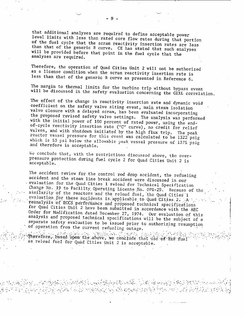
that additional analyses are required to define acceptable power level limits with less than rated core flow rates during that portion of the fuel cycle that the scram reactivity insertion rates are less than that of the generic B curve. CE has stated that such analyses will be provided before that point in the fuel cycle that the analyses are required.
Therefore, the operation of Quad Cities Unit 2 will not be authorized as a license condition when the scram reactivity insertion rate is less than that of the generic B curve as presented in Reference 6.
The margin to thermal limits for the turbine trip without bypass event will be discussed in the safety evaluation concerning the GEXL correlation.
The effect of the change in reactivity insertion rate and dynamic void coefficient on the safety valve sizing event, main steam isolation valve closure with a delayed scram, has been evaluated incorporating the proposed revised safety valve settings. The analysis was performed with the initial power of 100 percent of rated power, using the endof-cycle reactivity insertion rate ("C"I curve), no credit for relief valves, and with shutdown initiated by the high flux trip. The peak reactor vessel pressure for this event was calculated to be 1322 psig which is 53 psi below the allowable peak vessel pressure of 1375 psig and therefore is acceptable.
Ue conclude that, with the restrictions discussed above, the overpressure protection during fuel cycle 2 for Quad Cities Unit 2 is acceptable.
The accident review for the control rod drop accident, the refueling accident and the steam line break accident were discussed in our evaluation for the Quad Cities 1 reload -for Technical Specification Change No. 19 to Facility. Operating License .No. DPa-29. Because of the "similarity 'of the readtors 'and the reload fuel, 'the Quad Cities 'l evaluation fQr these accidents is..app-licable to- Quad -Cities. 2.' .A. .. reanalysis of ECCSpe'fooranc& and pr6posed technical-specifictations for Quad Cities Unit 2 have been submitted in accordance with the AEC Order for Modification dated December 27, 1974. Our evaluation of this analysis and proposed technical specifications will be the subject of a separate safety evaluation to be issued prior to authorizing resumption of-operation from the current refueling outage.
Theefre Medupon' the .abo e, we cbncli! e ta sf. 'fiief'I" "as reload fuel fo'r Quad Cities Unit 2 is acceptable.
-. • .. :. "..•. . .. 4.

- 10 -
2. Replacement of Relief Valve with a Relief/Safety'Valve and Change of Relief and Safety Valve Setpoints
In the Quad Cities Unit 2 reload submittal dated December 20, 1974, CE proposed changes in the Technical Specifications for Quad Cities Unit 2 to allow operation with a combination relief/safety valve in place of an electromatic relief valve. This change was previously authorized for Quad Cities Unit 1 by Amendment No. 8.to Facility Operating License No. DPR-29, issued May 24, 1974. The changes to Quad Cities Unit 2 and the supporting analyses are identical to those for Quad Cities Unit I except for the incorporation of a revised dynamic void coefficient as discussed in section 1 of this evaluation.
The changes to the Technical Specifications include requirements f6r the modified valve, increased pressure setpoints for the springloaded safety valves, and more rapid scram times for the control rods. The purpose of the modification and changes is to maintain a 25 psi margin between the calculated peak pressure and the lowest setting of the spring-loaded safety valves for the limiting anticipated pressurization transient, a turbine trip with failure of the turbine bypass valves. The need for the change results from the decrease in rate of negative reactivity insertion during a reactor scram as core average exposure increases. Since Quad Cities Units 1 and 2 are of identical design in features relevant to the evaluation and since the proposed change is identical to the Quad Cities I change, the analyses by the licensee and the evaluation by the NRC staff for the two reloads are nearly identical. The only differences are that the use of the revised dynamic void coefficient necessitates reduction of reactor power to 90 percent of rated rather than 93 percent of rated and that the core exposure at which the power reduction will start has been calculated to be 3200 MWD/T in NEDO-20693 rather than 4000 MWD/T calculated for Quad Cities Unit 1. (6) The staff evaluation for this change at Quad Cities Unit 1 is enclosed (dated June 5, 1974).
Coincident with the above change, the bases for the fuel damage safety limit is being revised to adopt the General Electric transition boiling correlation, GEXL. Our evaluation of the margin to the fuel damage limit during a turbine trip with failure of bypass transient will be discussed in a separate safety evaluation concerning use of the GEXL correlation as a basis for Technical Specifications.
Based on the above and subject to the conditios stated above, we conclude that the changeout of one electromatic r6lief valve to a relief/safety valve and the associated technical specification changes related to relief and safety valve settings amn operability are acceptable.

- 11 -
CONCLUSION
We have concluded, based on the considerations discussed above, that: (1) there is reasonable assurance that the health and safety of the public will not be endangered by operation in the proposed manner, and (2) such activities will be conducted in compliance with the Commission's regulations and the issuance of this amendment will not be inimical to the common defense and security or to the health and safety of the public.
Date: APR 21 1975
OFFICE,)"
SU RNAM E ".
D A T ." .................... ......................... ..............................................9 .. ....................................... ...................................................... . ..........................................................................
FOnn/Z AEC-318 (]Rev. 9-53) AEC•[ 0240 * U. S.* GOVERNMENT PRINTING OFFICEZ I974-5a6-|66
UNITEDSTATES NUCLEAR REGULATORY COMISSION
DOCKET W). 50-265
COAo!AOWFALTH EDISON COMPANY
NOTICE OF ISSUANCE OF AMENDMEWN TO FACILITY OPERMTING LICENSE
Notice is hereby given that the U. S. Nuclear Regulatory Commission
(the Coimmission) has issued Amendment No. 9 to Facility Operating License
No. DPR-30 issued to Commonwealth Edison Company (acting for itself and
on behalf of the Iowa-Illinois Gas and Electric Company) which revised
Technical Specifications for operation of the Quad Cities Nuclear Power
Station Unit 2 located in Rock Island County, Illinois. The amendment
is effective as of its date of issuance.
The amendment authorizes operation of Quad Cities Unit 2 using
WxS fuel assemblies, replacement of a relief valve with a relief/safety
valve, and changes to the reactor vessel relief and safety valve setpoints
in accordance with the application by Commonwealth Edison Company dated
December 13, 1974, as supplemented.
The application for the amendment complies with the standards and
requirements of the Atomic Energy Act of 1954, as amended (the Act), and
the Commission's rules and regulations. The Commission has made appropriate
findings as required by the Act and the Commission's rules and regulations
in 10 CFR Chapter I, which are set forth in the license amendment. No
request for a hearing or petition for leave to intervene was filed
following the Nbtice of Proposed Issuance of Amendment published in the
Federal Re-gister on January 7, 1975 (40 F.R. 1291).
V A • J.............................................. I................................. .... ..... .. I .............................................. I.............................................. I........................ ........ . ... . .... I ................................... SURNAME-)O
DATE * ....................... ....................
Form AEC-318 (Rev. 9-53) AECM 0240 * U. $S GOVIERNMENT PRINTING OFFICES: 1974-526.166
-2 -
For further details with respect to this action, see (1) the
application for amendment dated December 13, 1974, and supplements
thereto dated December 20, 1974, February 20 and 27, 1975, and
March 27, 1975, (2) Amendment No. 9 to License No. DPR-30, with Change
No. 24, and (3) the Commission's concurrently issued related Safety
Evaluation. All of these items are available for public inspection at
the Commission's Public Document Room, 1717 H Street, N. W., Washington,
D. C. and at the Moline Public Library at 504 - 17th Street, Moline,
Illinois 61265. A single copy of items (2) and (3) may be obtained
upon request addressed to the U. S. Nuclear Regulatory Commission,
Washington, D. C. 20555, Attention: Director, Division of Reactor
Licensing.
Dated at Bethesda, Maryland, this 21$ dayq o i I RTC FOR TrE NUCLEAR REGULATORY COMIISSION
Original signed bY
Dennis L. Zienumaf
Dennis L. Ziemann, Chief Operating Reactors Branch #2 Division of Reactor Licensing
OFFICE -. "
SURNAME "
DATE*1
Form ABC-318 (Rev. 9-53) AECM 0240 * U. S. GOVERNMENT PRINTING ORFICRI 1974-826-166Form AEC-318 (Rev. 9-53) AECM 0240 * U. S. G.OVERNMmNT PRINTING OFFICES 1974-1526-166
- .................................... ........................................... I .. ............................................. ............................................ . ........ .................................... ......................................
.......................................... - ............................................ . .............................................. .............................................. ............................................. ......................................
.............................. ............ . ............................................. .............................................. .............................................. ............................................. ......................................
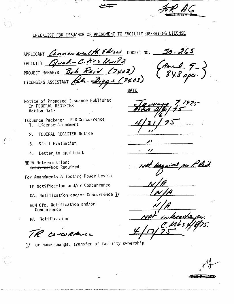
CHECKLIST FOR ISSUANCE OF AMENDMENT TO FACILITY OPERATING LICENSE
APPLICANT ____________ ___________ DOCKET NO.
FACILITY A~
PROJECT MANAGER 9 00 5 LICENSING ASSISTANT
DATE
Notice of Proposed Issuance Published In FEDERAL REGISTER Action Date
Issuance Package: ELD Concurrence 1. License Amendment
2. FEDERAL REGISTER Notice
3. Staff Evaluation
4. Letter to applicant
NEPA Determination: Re@M4-,eNot Required
For Amendments Affecting Power Level:
1E Notification and/or Concurrence
OAI Notification and/or Concurrence I
ADM OfQ. Notification and/or Concurrence
PA Notification
or name change, transfer of facility ownership
" 7 19.S
=VA/I1-
All4
---¢¢..¢¢•