qt qtqt & pl& plttt seriesseriesseries · this manual contains important safety information...
TRANSCRIPT

This manual contains important safety information and must becarefully read in its entirety and understood prior to installation byall personnel who install, operate and/or maintain this product.
Manual No. 50161-106
January 2009 Edition
QTQTQTQTQT® ® ® ® ® & PL& PL& PL& PL& PLTTTTT®®®®®
SeriesSeriesSeriesSeriesSeries2 Stage Compr2 Stage Compr2 Stage Compr2 Stage Compr2 Stage Compressorsessorsessorsessorsessors
Instruction Manual

Quincy Compressor
Warranty Statement
Standard WarrantyQuincy Compressor
QT & PLT Series Reciprocating Compressors
LIMITATIONS
Notice of the alleged defect must be given to the Seller in writing with all identifying details, including serial number, model number, type of equipment and date of purchase within thirty (30) days of discovery of same during the warranty period. If requested by Seller, such product or product thereof must be promptly returned to Seller, freight collect for inspection.
The Seller must have the warranty registration card on fi le at Quincy, IL. within ten (10) days of start-up or the warranty may be declared null and void.
The above warranties shall not apply and Seller shall not be responsible nor liable for:
(a) Consequential, collateral or special losses or damages.
(b) Equipment conditions caused by fair wear and tear, abnormal conditions, accident, neglect or misuse of equipment, improper storage or damages resulting during shipment.
(c) Deviation from operating instructions, specifi cations or other terms of sales.
(d) Labor charges, loss or damage resulting from improper operation, maintenance or repairs made by person(s) other than Seller or Seller’s authorized service station.
(e) Improper application or installation of product.
(f) Warranty travel expense is not covered on QT-5 & PLT-5 compressors sold as basics.
DISCLAIMER
In no event shall Seller be liable for any claims, whether arising from breach of contract or warranty or claims of negligence or negligent manufacture, in excess of the purchase price.
This warranty is the sole warranty of Seller and any other warranties, express, implied in law or implied in fact, including any warranties of merchantability and fi tness for particular use, are hereby specifi cally excluded.
GENERAL PROVISIONS
Quincy Compressor (The Seller) warrants to each retail purchaser (Purchaser) products of the Seller’s own manufacture against defects in material and workmanship. With respect to products not manufactured by the Seller, the Seller will, if practical, pass along the warranty of the original manufacturer.
The Seller’s sole obligation under this warranty shall be, at its option, to repair, replace, or refund the purchase price of any product or part thereof which is deemed to be defective, provided the Purchaser meets all of the applicable requirements of this warranty and none of the limitations apply.
WARRANTY PERIODS
Basic Compressors
Seller warrants for twelve (12) months from date of start-up or twenty-four (24) months from factory shipment, whichever occurs fi rst. This includes labor and approved travel. All warranty travel expense will be paid to the nearest authorized repair center.
Remanufactured Basics
Seller warrants for six (6) months from date of start-up or eighteen (18) months from date of factory shipment, whichever occurs fi rst. This includes labor and approved travel. All warranty travel expense will be paid to the nearest authorized repair center.
Replacement Parts
Seller warrants repaired or replaced parts of its own manufacture against defects in material and workmanship under normal use and service for ninety (90) days, or for the remainder of the warranty on the product being repaired, whichever is longer.
Parts purchased outside the compressor’s warranty period are warranted for ninety (90) days from the date of distributor sale, or one (1) year from the date of shipment from the factory, whichever occurs fi rst.
Normal maintenance items and procedures are not warranted unless found to be defective in material or workmanship, i.e. but not limited to fi lters, gaskets, rings, valves and control lines.

Quincy Compressor
Warranty Statement
True Blue WarrantyQuincy Compressor
PRO, MAX & Xtreme Reciprocating Compressor Units
LIMITATIONS
Notice of any alleged defect must be given to the Seller in writing, with all identifying details (including serial number, model number, type of equipment and date of purchase), within thirty (30) days of discovery, during the warranty period. If requested by the Seller, the defective product or portion thereof must be promptly returned to Seller for inspection.
The Seller must have the Purchaser’s warranty registration on fi le at Quincy, Illinois within ten (10) days of start-up, or this warranty may be declared null and void.
The above warranties shall not apply to and Seller shall not be liable for:
a. Equipment conditions caused by normal wear and tear, abnormal conditions, accident, neglect or misuse of equipment, improper storage or damages resulting during shipment;
b. Deviat ion from operat ing instruct ions, specifi cations or other terms of sales;
c. Labor charges, loss or damage resulting from improper operation, maintenance or repairs made by person(s) other than Seller or Seller’s authorized service station; or
d. Improper application or installation of product.
DISCLAIMER
THIS WARRANTY IS THE SOLE WARRANTY OF THE SELLER AND ANY AND ALL OTHER WARRANTIES, EXPRESS OR IMPLIED, INCLUDING ANY WARRANTIES OF MERCHANTABILITY AND FITNESS FOR PARTICULAR PURPOSE, ARE HEREBY SPECIFICALLY EXCLUDED. THE SELLER’S LIABILITY FOR ANY LOSS OR DAMAGE ARISING OUT OF OR RESULTING FROM OR IN ANY WAY CONNECTED WITH THE PRODUCTS SHALL NOT EXCEED PURCHASER’S PURCHASE PRICE FOR THE PARTICULAR PRODUCT UPON WHICH SUCH LIABILITY IS BASED, REGARDLESS OF WHETHER SUCH LIABILITY ARISES IN CONTRACT (INCLUDING, BUT NOT LIMITED TO, FAILURE OR DELAY IN PERFORMANCE OR DELIVERY DUE TO ANY CAUSE WHATSOEVER), TORT (INCLUDING, BUT NOT LIMITED TO, NEGLIGENCE OR STRICT LIABILITY) OR OTHERWISE. IN NO EVENT SHALL THE SELLER BE LIABLE FOR LOSS OF PROFITS OR REVENUE OR FOR ANY INCIDENTAL, CONSEQUENTIAL, INDIRECT, SPECIAL OR PUNITIVE DAMAGES.
WARRANTY PERIODS
Quincy Compressor (Seller) warrants original basic original basic compressorscompressors (see Standard Warranty for replacement basic compressors) on factory assembled PRO, MAX on factory assembled PRO, MAX and Xtreme unitsand Xtreme units for fi ve (5) years from date of start-up, provided Purchaser registers the product with Quincy Compressor and maintains the unit with Quincy genuine parts and lubricant. Rings and gaskets are covered for the entire fi ve (5) year period. Suction and discharge valves are covered for two (2) years.
The True Blue warranty covers approved parts, labor and travel per the schedule below:
One (1) year: Parts, Labor, and Travel - 100% Two (2) years: Parts, Labor, and Travel - 100% Three (3) years: Approved Parts and Labor - 100% Four (4) years: Approved Parts and Labor - 100% Five (5) years: Approved Parts and Labor - 100%
The complete PRO, MAX or Xtreme unit is warranted for two (2) years from date of start-up and includes labor, parts and approved travel.
Normal maintenance items, such as belts, fi lters, check valves and tank drains, are not warranted unless found to be defective in material or workmanship.
GENERAL PROVISIONS
Seller warrants, to each retail Purchaser, products of the Seller’s own manufacture, against defects in material and workmanship under normal use and service. With respect to products not manufactured by the Seller, the Seller will, if reasonably practical, pass along the warranty of the original manufacturer.
The Seller’s sole obligation under this warranty shall be, at its option, to repair, replace or refund the purchase price of any product or part thereof which is deemed by the Seller to be defective, provided the Purchaser meets all of the applicable requirements of this warranty and none of the limitations apply.
Requirements:1. Purchaser must register product with Seller via
www.quincycompressor.com or the registration card provided.
2. Purchaser must maintain the compressor with genuine Quincy Compressor parts and lubricants for entire warranty period (proof of purchase required).

QT & PLT Series Quincy Compressor
50161-106, January 2009 3501 Wismann Lane, Quincy Ill. - 62305-3116
ContentsSECTION 1SECTION 1SECTION 1SECTION 1SECTION 1 SAFETYSAFETYSAFETYSAFETYSAFETY
Safety First ............................................................................................................................................. 1Summary of Changes .............................................................................................................................. 3
SECTION 2SECTION 2SECTION 2SECTION 2SECTION 2 SYSTEM DYNAMICSSYSTEM DYNAMICSSYSTEM DYNAMICSSYSTEM DYNAMICSSYSTEM DYNAMICSDescription & Application ......................................................................................................................4Principles of Compression Cycles ..........................................................................................................4Principles of Lubrication Systems .........................................................................................................4Principles of Cooling Systems ................................................................................................................ 4Principles of Dryers & Filters ................................................................................................................ 5
SECTION 3SECTION 3SECTION 3SECTION 3SECTION 3 INSTINSTINSTINSTINSTALLAALLAALLAALLAALLATIONTIONTIONTIONTIONReceiving Delivery .................................................................................................................................. 6Freight Damage ......................................................................................................................................6Location................................................................................................................................................... 7Electrical Supply Requirements ............................................................................................................. 8Wiring & Piping Schematics .................................................................................................................. 9Mounting ............................................................................................................................................... 18System Components ............................................................................................................................. 18Induction System .................................................................................................................................. 20Compressed Air Discharge System ...................................................................................................... 20
SECTION 4SECTION 4SECTION 4SECTION 4SECTION 4 STSTSTSTSTARARARARART-UP & OPERAT-UP & OPERAT-UP & OPERAT-UP & OPERAT-UP & OPERATIONTIONTIONTIONTIONPre-Starting Checklist .......................................................................................................................... 24Initial Starting & Operating ................................................................................................................. 25Daily Starting Checklist ....................................................................................................................... 26
SECTION 5SECTION 5SECTION 5SECTION 5SECTION 5 MAINTENANCE & LUBRICAMAINTENANCE & LUBRICAMAINTENANCE & LUBRICAMAINTENANCE & LUBRICAMAINTENANCE & LUBRICATIONTIONTIONTIONTIONStopping for Maintenance ..................................................................................................................... 27Maintenance Schedule .......................................................................................................................... 27Maintenance Schedule Checklist Sample ............................................................................................ 27Lubrication ............................................................................................................................................ 29Pulley / Sheave Alignment & Belt Tension ......................................................................................... 30Pressure Switch Adjustment ................................................................................................................ 31Torquing Cylinder to Head Capscrews................................................................................................. 32Pilot Valve Adjustment Instructions .................................................................................................... 33
SECTION 6SECTION 6SECTION 6SECTION 6SECTION 6 TROUBLESHOOTINGTROUBLESHOOTINGTROUBLESHOOTINGTROUBLESHOOTINGTROUBLESHOOTINGTroubleshooting .................................................................................................................................... 34
SECTION 7SECTION 7SECTION 7SECTION 7SECTION 7 REFERENCE INFORMAREFERENCE INFORMAREFERENCE INFORMAREFERENCE INFORMAREFERENCE INFORMATIONTIONTIONTIONTIONDecal Locations ..................................................................................................................................... 38

QT & PLT Series Quincy Compressor
50161-106, January 2009 1 3501 Wismann Lane, Quincy Ill. - 62305-3116
SECTION 1SECTION 1SECTION 1SECTION 1SECTION 1 SAFETYSAFETYSAFETYSAFETYSAFETY
Safety First
At Quincy Compressor safety is not only a primary concern, but a faithfullyperformed practice. Beginning with the design stage, safety is built into “TheWorld’s Finest Compressor”. It is the intention of this manual to pass along the“safety first” concept to you by providing safety precautions throughout itspages.
“DANGER !”, “WARNING !”, and “CAUTION !” are displayed in largebold capital letters in the left hand column to call attention to areas of vitalconcern. They represent different degrees of hazard seriousness, as statedbelow. The safety precaution is spelled out in bold upper and lower case lettersin the right hand column.
Immediate hazards which will result in severe personal injury ordeath.
Hazards or unsafe practices that could result in personal injury ordeath.
Hazards or unsafe practices which could result in minor personalinjury, product or property damage.
Each section of this instruction manual, as well as any instructions suppliedby manufacturers of supporting equipment, should be read and understoodprior to starting the compressor. If there are any questions regarding any partof the instructions, please call your local Quincy distributor, or the QuincyCompressor factory before creating a potentially hazardous situation. Life,limb, or equipment could be saved with a simple phone call.
Compressors are precision high speed mechanical equipment requiringcaution in operation to minimize hazard to property and personnel. There aremany obvious safety rules that must be observed in the operation of this typeof equipment. Listed below are some additional safety precautions that mustbe observed.
•Transfer of toxic, dangerous, flammable or explosive substances using QuincyCompressor products is at the user’s risk.
•Turn off and lockout/tagout (per OSHA regulation 1910.147) the main powerdisconnect switch before attempting to work or perform any maintenance.
•Do not attempt to service any part of the unit while it is operating.
•Per OSHA regulation 1910.147, relieve the system of all pressure beforeattempting to service any part of the unit.
•Allow ample time for the compressor to cool before performing serviceprocedures. Some surface temperatures exceed 350°F when the compressor isoperating.
WARNING !
CAUTION !
DANGER !

QT & PLT Series Quincy Compressor
50161-106, January 2009 2 3501 Wismann Lane, Quincy Ill. - 62305-3116
•Do not operate the unit with any of its safety guards, shields, screens,enclosure panels or doors removed.
•Do not remove or paint over any DANGER!, WARNING!, CAUTION!, orinstructional materials attached to the compressor. Lack of information re-garding hazardous conditions can cause property damage or personal injury.
•Periodically check all pressure relief valves for proper operation.
•Do not change the pressure setting of the pressure relief valve, restrict thefunction of the pressure relief valve, or replace the pressure relief valve witha plug.
•Do not install a shutoff valve in the compressor discharge line without firstinstalling a pressure relief valve of proper size and design between the shutoffvalve and the compressor.
•Do not use plastic pipe, rubber hose, or lead-tin soldered joints in any part ofthe compressed air system.
•Alterations must not be made to this compressor without Quincy Compressor’sapproval.
•Be sure that all tools, shipping and installation debris have been removedfrom the compressor and installation site prior to starting the compressor.
•Do not operate the compressor in excess of the ASME pressure vessel ratingfor the receiver or the service rating of the compressor, whichever is lower.
•Make a general overall inspection of the unit daily and correct any unsafesituations. All fasteners must be kept tight.
•Reckless behaviour of any kind involving compressed air is dangerous andcan cause very serious injury to the participants.
•Provisions should be made to have the instruction manual readily availableto the operator and maintenance personnel. If for any reason any part of themanual becomes illegible or the manual is lost, have it replaced immediately.The instruction manual should be read periodically to refresh one’s memory. Itmay prevent a serious or fatal accident.
•Never use a flammable or toxic solvent for cleaning the air filter or any parts.
Air used for breathing or food processing must meet OSHA 29 CFR1910.134 or FDA 21 CFR 178.3570 regulations. Failure to do so maycause severe injury or death.
Oil and moisture residue must be drained from the air receiverdaily or after each use. Accumulations of oil residue in the receivercan be ignited by embers of carbon created by the heat of compres-sion, causing an explosion, damage to property and injury to per-sonnel.
DANGER !
WARNING !
QT & PLT Series Quincy Compressor
50161-106, January 2009 3 3501 Wismann Lane, Quincy Ill. - 62305-3116
The owner, lessor or operator of any compressor unit manufactured byQuincy Compressor is hereby warned that failure to observe the safetyprecautions and procedures outlined in this manual may result in seriouspersonal injury, damage to property, and may void your warranty. QuincyCompressor must authorize all warranty service. Before contacting yourdistributor or the factory, check the maintenance requirements and thetroubleshooting guide for your compressor. Most warranty issues can beresolved by following proper maintenance procedures.
Quincy Compressor neither states as fact, nor in any way implies that theabove list of safety precautions is an all inclusive list, the observance of whichwill prevent all damage to property or injury to personnel.
Every effort has been taken to ensure that complete and correct instructionshave been included in this manual. However, possible product updates andchanges may have occurred since this printing. Quincy Compressor reservesthe right to change specifications without incurring any obligation for equip-ment previously or subsequently sold.
Summary of Changes to This Manual(since previous printing dated October 2008):
· Specifications were removed from this manual and added to the QTTeardown & Rebuild instruction manual.
· QT-30 crankcase lubricant capacity was added.
· Xtreme and Quin-Cip-D information was added.
QT & PLT Series Quincy Compressor
50161-106, January 2009 4 3501 Wismann Lane, Quincy Ill. - 62305-3116
SECTION 2SECTION 2SECTION 2SECTION 2SECTION 2 SYSTEM DYNAMICSSYSTEM DYNAMICSSYSTEM DYNAMICSSYSTEM DYNAMICSSYSTEM DYNAMICS
Description & Application
Quincy Compressor QT Series and PLT Series compressors are heavy duty, aircooled, belt driven compressors. QT Series two stage compressors are splashlubricated and capable of delivering 175 PSIG of compressed air. The PLTSeries compressors are pressure lubricated and capable of delivering 175 PSIGof compressed air.
Principles of Compression Cycles
Two Stage Compressors
During the downstroke of the piston of a two stage compressor, air is drawnthrough an intake valve in the head of the compressor into the low pressurecylinder and compressed during the upstroke of the piston.
The compressed air is then released through a discharge valve in the headof the compressor to an intercooler (usually finned tubing) where the heatresulting from compression is allowed to dissipate. The cooler compressed airis then drawn into a second compression cylinder, the high pressure cylinder,for compression to final pressure.
From there the compressed air is released through a discharge valve to anair receiver tank or directly to a network of compressed air supply lines. In onerevolution of the crankshaft a compression cycle is completed.
Principles of Lubrication Systems
Splash Lubricated Compressors (QT Series)
With each stroke of the compressor, a dipper attached to the bottom of theconnecting rod , dips into an oil bath at the bottom of the crankcase. This dippersplashes oil throughout the interior of the crankcase, lubricating all movingparts.
It is important with this system that the correct oil level be maintained. Ifthe oil level is too high, excessive oil carryover could result. If the oil level is toolow, or the compressor is not operated within the correct RPM range, themoving parts will not be adequately lubricated.
Pressure Lubricated Compressors (PLT Series)
Moving parts within the crankcase are supplied with lubrication by a positivedisplacement, gerotor type oil pump. Oil is drawn up from the bottom of thecrankcase to the oil pump through an oil sump strainer screen. Oil travelsunder pressure through drilled journals in the crankshaft to lubricate crank-shaft bearings and connecting journals.
Principles of Cooling Systems
QT & PLT compressors are equipped with a compressor sheave with fan blades.These fan blades force ambient air across cylinder head and intercooler fins tocool the compressor. Xtreme compressor units are equipped with a compressorsheave and a fan mounted on the motor shaft. These fans force air through the
QT & PLT Series Quincy Compressor
50161-106, January 2009 5 3501 Wismann Lane, Quincy Ill. - 62305-3116
enclosure, across the motor, compressor and intercooler. These compressors aredesigned to be operated with the compressor sheave turning in a counterclock-wise rotation (as viewed “tummy to the sheave”). QT, PLT and Xtremecompressors should be operated in temperatures under 104°F.
Principles of Dryers & Filters
Moisture occurs naturally in air lines as a result of compression. Moisturevapor in ambient air is concentrated when pressurized and condenses whencooled in downstream air piping. Compressed air dryers reduce the moisturevapor concentration and prevent water formation in compressed air lines.Dryers are a recommended companion to filters, aftercoolers, and automaticdrains for improving the productivity of compressed air systems.
Water and moisture vapor removal increases the efficiency of air operatedequipment, reduces contamination and rusting, increases the service life ofpneumatic equipment and tools, prevents air line freeze-ups, and reducesproduct rejects.

QT & PLT Series Quincy Compressor
50161-106, January 2009 6 3501 Wismann Lane, Quincy Ill. - 62305-3116
SECTION 3SECTION 3SECTION 3SECTION 3SECTION 3 INSTALLATIONINSTALLATIONINSTALLATIONINSTALLATIONINSTALLATION
Receiving Delivery
Immediately upon receipt of compressor equipment and prior to completelyuncrating, the following steps should be taken:
Step 1) Inspect compressor equipment for damage that may have occurredduring shipment. If any damage is found, demand an inspectionfrom the carrier. Ask the carrier how to file a claim for shippingdamages. (Refer to SECTION 3, Freight Damage for completedetails.) Shipping damage is not covered by Quincy Com-pressor warranty.
Step 2) Insure that adequate lifting equipment is available for moving thecompressor equipment.
Improper lifting can result in component or system damage, orpersonal injury. Follow good shop practices and safety procedureswhen moving the unit.
Step 3) Read the compressor nameplate to verify the model and sizeordered.
Step 4) Read the motor nameplate to be sure the motor is compatible withyour electrical conditions (volts, phase, hertz).
Step 5) Read the pressure relief valve nameplate to be sure it does notexceed the working pressure shown on the compressor or any othercomponent in the system.
Step 6) Read and understand the safety precautions containedwithin this manual. The successful and efficient operation ofcompressor equipment depends largely upon the amount of caretaken to install and maintain the equipment. Quincy Compressorstrongly recommends that any or all person(s) in charge of install-ing, maintaining, or servicing one of our compressors read andunderstand the entire contents of this manual in order to performsuch duties safely and efficiently.
Freight Damage
It is extremely important that you examine every carton and crate as soon asyou receive it. If there is any obvious damage to the shipping container, havethe delivering carrier sign the freight bill, noting the apparent damage, andrequest a damage report.
If concealed damage is discovered at a later date, the carrier mustbe notified within 15 days of initial receipt of freight. Concealedshipping damage is not covered by Quincy Compressor Warranty.Contact the carrier as soon as possible, giving them an opportunity to inspectthe shipment at the premises where the delivery was made. Do not move thedamaged freight from the premises where the original delivery was made.
WARNING !

QT & PLT Series Quincy Compressor
50161-106, January 2009 7 3501 Wismann Lane, Quincy Ill. - 62305-3116
Retain all containers and packing for inspection by the carrier.
A claim form can be requested from the carrier: Standard Form for Presen-tation of Loss and Damage Claims (form # 3208). Your claim will need to besubstantiated with the following documents:
a.) form #3208
b.) original bill of lading
c.) original paid freight bill
d.) original invoice or certified copy
e.) other particulars obtainable in proof of loss or damage (photos,damage inspection, etc.)
The proper description and classification of our product in the NationalMotor Freight Classification 100-H, contained in item 118100, reads as follows:Compressors, air, or air ends: with or without air tanks, hose or nozzles,mounted or not mounted.”
We suggest that these instructions be circulated to your shipping andreceiving personnel.
Location
QT & PLT Series air compressors should be installed in an area that is clean,dry, well lighted, adequately ventilated, and not less than 24 inches to a wallor other compressor. (Note: A gas engine will produce carbon monoxide; alwaysprovide adequate ventilation!) Inspection and maintenance checks are re-quired daily. Therefore, sufficient space needs to be provided around thecompressor for safe and proper inspection, cleaning, and maintenance.
Ample circulation of air must be provided across the compressor cylinders,heads and cooler (if so equipped). If at all possible, the pulley drive system (i.e.motor pulley, compressor sheave, belts and guard) should be located next to awall to minimize any danger created by the drive system while the compressoris operating. Do not allow hot air from additional equipment to blow towardsthe compressor.
QT & PLT series compressors should be operated in temperatures under104°F. In cold climates, the compressor should be installed in a heated building.
Do not operate this compressor in ambient temperatures lowerthan -15° F. A crankcase heater is recommended for a compressorthat is to operate in temperatures under 32° F.
Under no circumstances should a compressor be used in an areathat may be exposed to toxic, volatile, or corrosive atmosphere. Donot store toxic, volatile, or corrosive agents near the compressor.
Noise
Noise is a potential health hazard that must be considered. There are federaland local laws governing acceptable noise levels. Check with local officials forspecifications.
CAUTION !
WARNING !
QT & PLT Series Quincy Compressor
50161-106, January 2009 8 3501 Wismann Lane, Quincy Ill. - 62305-3116
Excessive noise can be effectively reduced through various methods. Totalenclosures, intake silencers, baffle walls, relocating or isolating the compressorcan reduce noise levels. Care must be taken when constructing total enclosuresor baffle walls. If not properly constructed or positioned, they could contributeto unacceptable noise levels or overheating. Consult your local Quincy distribu-tor if assistance is required.
Unusual noise or vibration indicates a problem. Do not operate thecompressor until the source has been identified and corrected.
Electrical Supply Requirements
The electrical installation of this unit should be performed by a qualifiedelectrician with knowledge of the National Electrical Code (NEC), OSHA codeand/or any local or state codes having precedence.
Before installation, the electrical supply should be checked for adequatewire size and transformer capacity. Verify that the electrical supply voltagematches the requirements of the motor. A suitable circuit breaker or fuseddisconnect switch should be provided. When a 3 phase motor is used to drivea compressor, any unreasonable voltage imbalance between the legs must beeliminated and any high or low voltage corrected to prevent excessive currentdraw. Note: This unit must be grounded.
The installation, electric motor, wiring, and all electrical controls must be inaccordance with NFPA 70-1996 National Electric Code, National ElectricSafety Code, state and local codes. Failure to abide by the national, state andlocal codes may result in physical harm and/or property damage.
High voltage may cause personal injury or death. Disconnect andlockout/tagout per OSHA regulation 1910.147 all electrical powersupplies before opening the electrical enclosure or servicing.
Never assume a compressor is safe to work on just because it is notoperating. It could restart at any time. Follow all safety precautionsoutlined in SECTION 5, Stopping For Maintenance.
Electrical enclosures and components must be in compliance withNEMA environmental ratings for the areas in which they are beinginstalled.
WARNING !
DANGER !
WARNING !
WARNING !

QT & PLT Series Quincy Compressor
50161-106, January 2009 9 3501 Wismann Lane, Quincy Ill. - 62305-3116
Fig
. 3-1
3 P
has
e M
agn
etic
Mot
or S
tart
er W
ith
Au
tom
atic
Sta
rt /
Sto
p C
ontr
olW
irin
g S
chem
atic
WP
1744
A (
Rev
. D)
See
Fig
.s 3
-5 &
3-6
for
Xtr
eme
(Cab
inet
Un
its)
Wir
ing
Sch
emat
ics
Mag
netic
Sta
rter
Con
tact
or
Ove
rload
Rel
ay
Con
nect
inco
min
g po
wer
line
sat
scr
ew te
rmin
als
L1, L
2 &
L3.

QT & PLT Series Quincy Compressor
50161-106, January 2009 10 3501 Wismann Lane, Quincy Ill. - 62305-3116
Fig
. 3-2
Sin
gle
Ph
ase
Mag
net
ic M
otor
Sta
rter
Wit
h A
uto
mat
ic S
tart
/ S
top
Con
trol
Wir
ing
Sch
emat
ic W
P17
44B
(R
ev. D
)S
ee P
ages
13
& 1
4 fo
r X
trem
e (C
abin
et U
nit
s) W
irin
g S
chem
atic
s
Mag
netic
Sta
rter
Con
tact
or
Ove
rload
Rel
ay
Con
nect
inco
min
g po
wer
line
sat
scr
ew te
rmin
als
L1 &
L2.

QT & PLT Series Quincy Compressor
50161-106, January 2009 11 3501 Wismann Lane, Quincy Ill. - 62305-3116
Inst
all i
ncom
ing
pow
er li
neco
nnec
tions
at s
crew
term
inal
sL1
& L
2.
Pres
sure
Sw
itch
Con
nect
inco
min
g po
wer
line
at th
is s
crew
term
inal
.
Splic
e in
com
ing
pow
er li
neco
nnec
tion
to th
is w
hite
wire
(wra
pped
in re
d ta
pe).
Fig
. 3-3
Sin
gle
Ph
ase
5 h
p-2
30V
Eco
nom
y U
nit
sA
uto
mat
ic S
tart
/ S
top
Con
trol
- Pre
ssu
re S
wit
ch W
ired
to
Mot
orW
irin
g S
chem
atic
WP
1753
(R
ev. H
)S
ee F
ig.s
3-5
& 3
-6 fo
r X
trem
e (C
abin
et U
nit
s) W
irin
g S
chem
atic
s
QT & PLT Series Quincy Compressor
50161-106, January 2009 12 3501 Wismann Lane, Quincy Ill. - 62305-3116
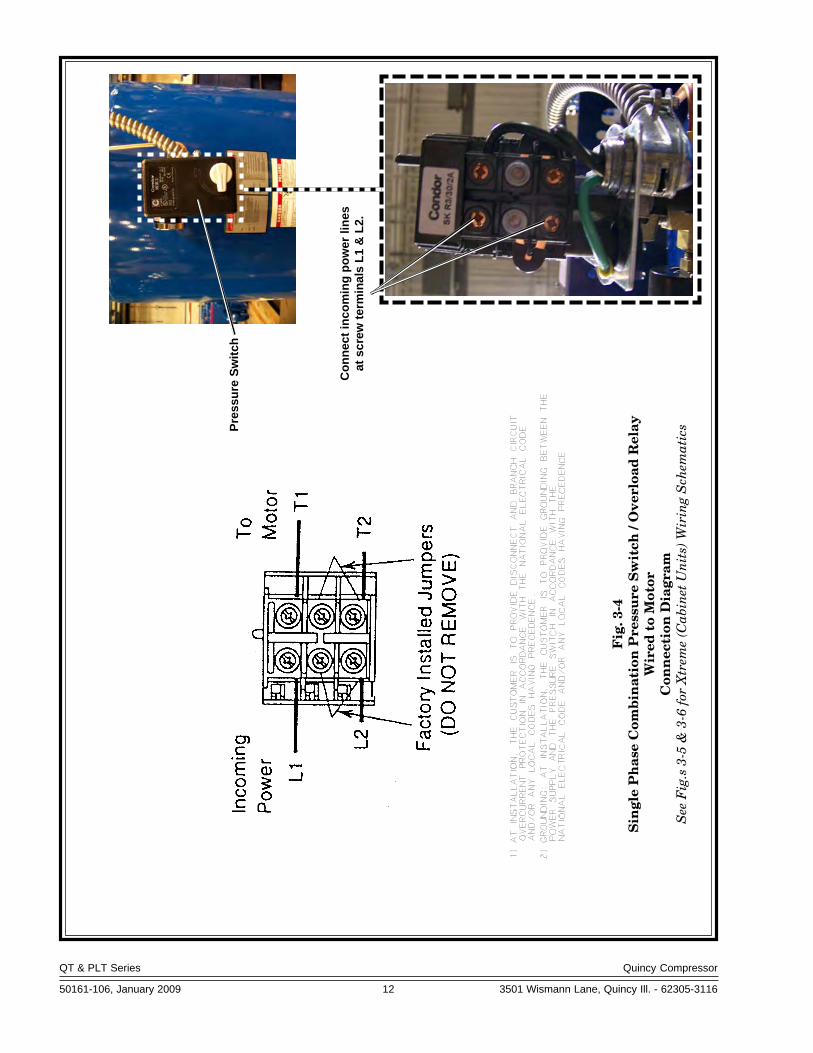
Fig
. 3-4
Sin
gle
Ph
ase
Com
bin
atio
n P
ress
ure
Sw
itch
/ O
verl
oad
Rel
ayW
ired
to
Mot
orC
onn
ecti
on D
iagr
amS
ee F
ig.s
3-5
& 3
-6 fo
r X
trem
e (C
abin
et U
nit
s) W
irin
g S
chem
atic
s
Con
nect
inco
min
g po
wer
line
sat
scr
ew te
rmin
als
L1 &
L2.
Pres
sure
Sw
itch
QT & PLT Series Quincy Compressor
50161-106, January 2009 13 3501 Wismann Lane, Quincy Ill. - 62305-3116
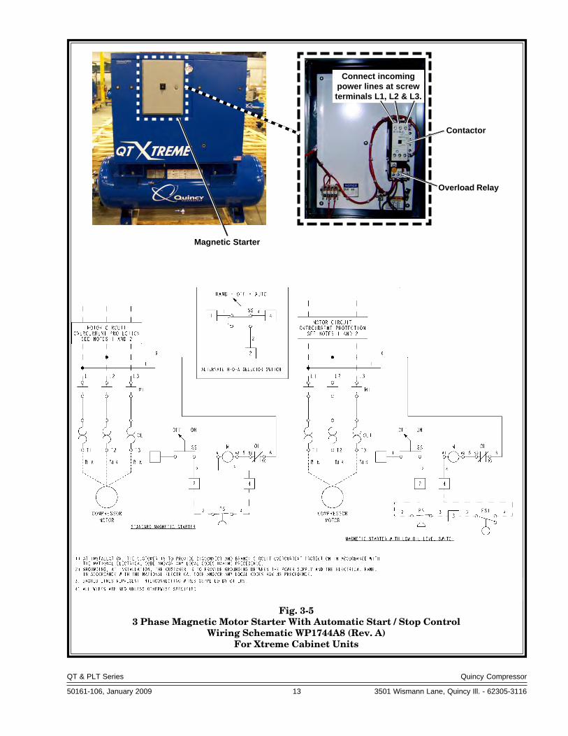
Fig. 3-53 Phase Magnetic Motor Starter With Automatic Start / Stop Control
Wiring Schematic WP1744A8 (Rev. A)For Xtreme Cabinet Units
Connect incomingpower lines at screwterminals L1, L2 & L3.
Contactor
Overload Relay
Magnetic Starter
QT & PLT Series Quincy Compressor
50161-106, January 2009 14 3501 Wismann Lane, Quincy Ill. - 62305-3116
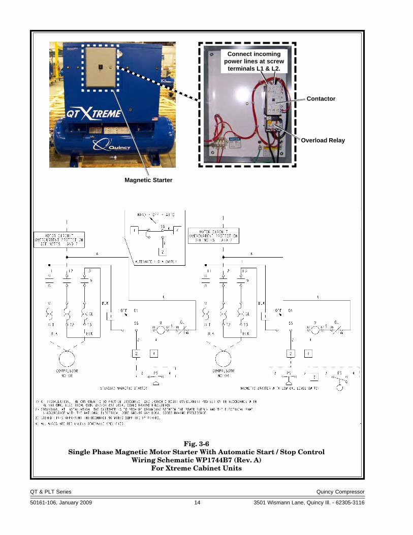
Fig. 3-6Single Phase Magnetic Motor Starter With Automatic Start / Stop Control
Wiring Schematic WP1744B7 (Rev. A)For Xtreme Cabinet Units
Connect incomingpower lines at screw
terminals L1 & L2.
Contactor
Overload Relay
Magnetic Starter

QT & PLT Series Quincy Compressor
50161-106, January 2009 15 3501 Wismann Lane, Quincy Ill. - 62305-3116
Fig. 3-7Start / Stop Control
Piping Schematic WP1781B

QT & PLT Series Quincy Compressor
50161-106, January 2009 16 3501 Wismann Lane, Quincy Ill. - 62305-3116
Fig. 3-8Continuous Run - Load / Unload Control
Piping Schematic WP1781C

QT & PLT Series Quincy Compressor
50161-106, January 2009 17 3501 Wismann Lane, Quincy Ill. - 62305-3116
Fig. 3-9Dual Control with Pilot Valve Unloading
Piping Schematic WP1781A

QT & PLT Series Quincy Compressor
50161-106, January 2009 18 3501 Wismann Lane, Quincy Ill. - 62305-3116
Mounting
Proper mounting of QT & PLT series compressor units is crucial to the safeoperation and longevity of the equipment. The installation requires a flat and
level concrete floor or pad (for mobile units see MountingMobile Units). Satisfactory results can usually be ob-tained by mounting the compressor unit on vibrationisolating pads available from your local Quincy distribu-tor. All vertical tank units must be anchored! Refer toFig. 3-7, Isolator Installation for Unanchored orAnchored Receiver.
State or local codes may mandate that the compressorbe bolted to the floor. In this case the unit must be leveledand bolted making absolutely certain the feet are notstressed in any manner. Leave the flange nut loose &lock it with a back-up nut! Uneven feet drawn tightlyto the concrete pad will cause severe vibrations resultingin cracked welds or fatigue failure. The customer isresponsible for providing a suitable foundation & isolatormounting where necessary.
Mounting Mobile Units
Gas engine driven compressors mounted to truck beds should be fastened insuch a way so as not to create any stress to the air receiver tank. Truck beds,characteristically, have a tendency to flex and could cause damage to thereceiver tank if the tank is fastened directly to the truck bed. It is the user’sresponsibility to provide an adequate means of fastening the unit in theseapplications.
Do not operate this compressor more than 15° off level or move itwhile it is operating.
System components
Efficiency and safety are the primary concerns when selecting components forcompressed air systems. Products of inferior quality can not only hinderperformance of the unit, but could cause system failures that result in bodilyharm or even death. Select only top quality components for your system. Callyour local Quincy distributor for quality parts and professional advice.
Drive Pulleys / Sheaves
Various pulley and sheave combinations are available to obtain the desired airpressure and delivery rate of your compressor. Consideration must be given tothese combinations to ensure that the motor is not overloaded by operatingabove or below the designed speed range.
Whatever combination is employed, the drive pulleys & compressor sheavesmust be properly aligned and drive belt tension set to specifications (refer toSECTION 5, Pulley / Sheave Alignment & Belt Tension). Improper pulley/sheave alignment and belt tension can cause motor overloading, excessivevibration, and premature belt and/or bearing failure.
110365Fig. 3-7 Isolator Installation for
Unanchored or Anchored Receiver
FLANGE NUT
RECEIVER FOOT
ISOLATOR BACKING
PLATE
BOLT
ISOLATOR
FLANGE NUT
Leave loose & lockwith a back-up nut
RECEIVER FOOT
ISOLATOR BACKINGPLATE OR SHIMS IFNECESSARY
ISOLATOR
ANCHOREDFLOORSTUD
UNANCHORED ANCHORED
CAUTION !
QT & PLT Series Quincy Compressor
50161-106, January 2009 19 3501 Wismann Lane, Quincy Ill. - 62305-3116
Excessive compressor RPM’s (speed) could cause a pulley or sheaveto shatter. In an instant, the pulley or sheave could separate intofragments capable of penetrating the belt guard and causing bodilyharm or death. Do not operate the compressor above the recom-mended RPM (refer to SECTION 2, Specifications).
Guards
All mechanical action or motion is hazardous in varying degrees and needs tobe guarded. Guards should be designed to achieve the required degree ofprotection and still allow full air flow from the compressor sheave across theunit. Guards shall be in compliance with OSHA safety and health standards 29CFR 1910.219 in OSHA manual 2206 and any state or local codes.
Guards must be fastened in place before starting the compressorand never removed before cutting off and locking out the mainpower supply.
Check Valves
Check valves are designed to prevent back-flow of air pressure in the com-pressed air system (air flows freely in one direction only). The check valve mustbe properly sized for air flow and temperature. Do not rely upon a checkvalve to isolate a compressor from a pressurized tank or compressedair delivery system during maintenance procedures!
Manual Shutoff Valves
Manual shutoff valves block the flow of air pressure in either direction. Thistype of valve can be used to isolate a compressor from a pressurized system,provided the system is equipped with a pressure relief valve capable of beingmanually released. The pressure relief valve should be installed between themanual shutoff valve and the compressor (refer to Fig. 3-8, Typical Drop Leg& Component Location).
Pressure Relief Valves
Pressure relief valves aid in preventing system failures by relieving systempressure when compressed air reaches a determined level. They are availablein various pressure settings to accommodate a range of applications. Pressurerelief valves are preset by the manufacturer and under no circumstancesshould the setting be changed by anyone other than the manufacturer.
Pressure relief valves are designed to protect compressed airsystems in accordance with ASME B19 safety standards. Failure toprovide properly sized pressure relief valves may cause propertydamage, severe personal injury or even death.
Pressure Switch
The pressure switch detects the demand for compressed air and allows themotor to start. When the demand is satisfied, the unit stops. Pressure switchesprovided by Quincy Compressor are pre-set at the factory and usually do notrequire adjustment.
WARNING !
DANGER !
WARNING !
QT & PLT Series Quincy Compressor
50161-106, January 2009 20 3501 Wismann Lane, Quincy Ill. - 62305-3116
Induction System
Air Intake
A clean, cool and dry air supply is essential to the satisfactory operation of yourQuincy QT or PLT Series air compressor. The standard air filter that thecompressor is equipped with when leaving the factory is of sufficient size anddesign to meet normal conditions, when properly serviced, in accordance withthe maintenance section of this manual.
If, however, the compressor is to be installed in a location where considerabledust, dirt and other contaminants are prevalent, consult your local Quincydistributor for advice and optional filters. A condensate trap must be installedas close as possible to the inlet filter if, as a result of installation or environmen-tal conditions, there is any risk of moisture forming in the inlet piping. It is theuser’s responsibility to provide adequate filtration for those conditions. Oilbath filters are not to be used. Warranty will be void if a failure is determinedto be caused by inadequate filtration.
Remote Inlet Filters (does not apply to Xtreme cabinet units)
Depending on the size of the compressor and the size and construction of theroom in which the unit operates, the air inlet may have to be located outside ofthe room. If it is necessary to remotely install the air filter, make the inlet pipingas short and direct as possible. Remotely installed air filters can lead tovibrations in the inlet piping. These vibrations can be minimized by adding apulsation dampener in the inlet piping between the remote inlet filter(s) andthe compressor.
If the inlet is routed to outside atmosphere, the inlet piping should beequipped with a hooded air filter and designed to prevent condensate, water orsnow from being injested into the compressor.
All inlet piping should be at least the same size (or larger) in diameter as theinlet connection to the compressor. For every 10 feet of inlet piping or every 90°bend, increase the inlet piping diameter by one pipe size. The inlet piping mustbe thoroughly clean inside. Remove all weld slag, rust or dirt. Galvanized pipewith threaded or flanged fittings is preferred.
Never locate the compressor air inlet system where toxic, volatileor corrosive vapors, air temperatures exceeding 100°F, water, orextremely dirty air could be ingested. These types of atmospherescould adversely affect the performance of the compressor system.
Compressed Air Discharge System
The discharge piping should be of the same diameter as the compressordischarge connection, or sized so that the pressure drop at any point in thesystem does not exceed 10% of the air receiver pressure. Install auxiliary airreceivers near heavy loads or at the far end of a long system. This will insuresufficient pressure if the use is intermittent, or sudden large demands areplaced on the system.
Discharge piping should slope to a drop leg (refer to Fig. 3-8, Typical DropLeg & Component Location) or moisture trap to provide a collection point
CAUTION !

QT & PLT Series Quincy Compressor
50161-106, January 2009 21 3501 Wismann Lane, Quincy Ill. - 62305-3116
where moisture can be easily removed. All service line outlets should beinstalled above the moisture traps to prevent moisture from entering the toolor device using the air. Manual shutoff valves, protected by pressure reliefvalves, should be installed at all service line outlets to eliminate leakage whilethe tools are not in use.
As with any piping, all parts of the discharge piping should fit so as not tocreate any stress between the piping and components.
Pneumatic Circuit Breakers or Velocity Fuses
The Occupational Safety and Health Act (OSHA), Section 1926.303, Paragraph7, published in the Code of Federal Regulations 29 CFR 1920.1, revised July 1,1982 states that all hoses exceeding 1/2" inside diameter shall have a safetydevice at the source of supply or branch line to reduce pressure in case of a hosefailure”
These pneumatic safety devices are designed to prevent hoses from whip-ping and/or the loss of hazardous or toxic gasses, all of which could result in aserious or fatal accident.
Never join pipes or fittings with lead-tin soldering. Welded orthreaded steel pipes and cast iron fittings, designed for the pres-sures and temperatures, are recommended.
Pressure Vessels
Air receiver tanks and other pressure containing vessels such as (but notlimited to) pulsation bottles, heat exchangers, moisture separators and traps,must be in accordance with ASME Boiler and Pressure Vessel Code Section VIIIand ANSI B19.3 safety standards. They must be equipped with a properly sizedpressure relief valve, pressure gauge, tank drain, & manual shutoff valve (refer
Fig. 3-8 Typical Drop Leg & Component Location Pix 1007-004
WARNING !
QT & PLT Series Quincy Compressor
50161-106, January 2009 22 3501 Wismann Lane, Quincy Ill. - 62305-3116
to Fig. 3-8, Typical Drop Leg & Component Location).
Follow ASME code for air reciever tanks and other pressure con-taining vessels. Pressure vessels must not be modified, welded,repaired, reworked or subjected to operating conditions outsidethe nameplate ratings. Such actions will negate code status, affectinsurance status and may cause property damage, severe injury oreven death.
A drain valve should be located in the bottom of the air receiver to allow formoisture drainage. An automatic drain valve is recommended. Extend pipingaway from the unit and any personnel in the immediate area to provide safe andconvenient removal of excess moisture.
If the air receiver is going to be subject to temperatures of 32°F or below,provisions must be made to guard against freezing of the pressure relief valves,check valves, pressure gauge, and moisture drain.
Condensation
Rust can form inside the crankcase and on internal components as a result ofcondensation. A compressor must operate long enough during each run cycleto reach full operating temperature in order to reduce the risk of condensation.
Lubricant that appears milky on the dipstick may have mixed withcondensate. Failure to replace contaminated lubricant will resultin damage to the compressor and may void warranty.
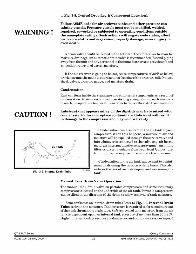
Condensation can also form in the air tank of yourcompressor. When this happens, a mixture of air andmoisture will be expelled through the service valve andinto whatever is connected to the valve (e.g. air hoses,metal air lines, pneumatic tools, spray guns). An in-linefilter or dryer, available from your local Quincy dis-tributor, may be required to eliminate the moisture.
Condensation in the air tank can be kept to a mini-mum by draining the tank on a daily basis. This alsoreduces the risk of rust developing and weakening thetank.
Manual Tank Drain Valve Operation
The manual tank drain valve on portable compressors and some stationarycompressors is located on the underside of the air tank. Portable compressorscan be tilted in the direction of the drain to allow removal of tank moisture.
Some tanks use an internal drain tube (Refer to Fig. 3-9, Internal DrainTube) to drain the moisture. Tank pressure is required to force moisture outof the tank through the drain tube. Safe removal of tank moisture from the airtank is dependent upon an internal tank pressure of no more than 30 PSIG.Higher internal tank pressures are dangerous and could cause serious injury!
WARNING !
Pix 1224Fig. 3-9 Internal Drain Tube
30 PSIG
CAUTION !
QT & PLT Series Quincy Compressor
50161-106, January 2009 23 3501 Wismann Lane, Quincy Ill. - 62305-3116
Oil and moisture residue must be drained from the air receiverdaily or after each use. Accumulations of oil residue in the receivercan be ignited by embers of carbon created by the heat of compres-sion, causing an explosion, damage to property and injury to per-sonnel.
Do not open a manual tank drain valve on any air tank containingmore than 30 PSIG of air pressure!
Never attempt to relieve an air tank by removing a pipe plug or anyother system component!
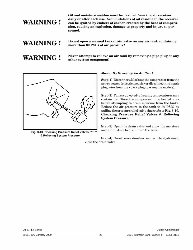
Manually Draining An Air Tank:
Step 1) Disconnect & lockout the compressor from thepower source (electric models) or disconnect the sparkplug wire from the spark plug (gas engine models).
Step 2) Tanks subjected to freezing temperatures maycontain ice. Store the compressor in a heated areabefore attempting to drain moisture from the tanks.Reduce the air pressure in the tank to 30 PSIG bypulling the pressure relief valve ring (refer to Fig. 3-10,Checking Pressure Relief Valves & RelievingSystem Pressure).
Step 3) Open the drain valve and allow the moistureand air mixture to drain from the tank.
Step 4) Once the moisture has been completely drained,close the drain valve.
Pix 1160Fig. 3-10 Checking Pressure Relief Valves& Relieving System Pressure
WARNING !
WARNING !
WARNING !
QT & PLT Series Quincy Compressor
50161-106, January 2009 24 3501 Wismann Lane, Quincy Ill. - 62305-3116
SECTION 4SECTION 4SECTION 4SECTION 4SECTION 4 START-UP & OPERATIONSTART-UP & OPERATIONSTART-UP & OPERATIONSTART-UP & OPERATIONSTART-UP & OPERATION
Pre-starting Checklist
Never assume a compressor is safe to work on just because it is notoperating. It could restart at any time. Follow all safety precautionsoutlined in SECTION 5, Stopping For Maintenance.
Failure to perform the pre-starting checklist may result in me-chanical failure, property damage, serious injury or even death.
Steps 1 through 12 should be performed prior to connecting theunit to a power source. If any condition of the checklist is not satisfied, makethe necessary adjustments or corrections before starting the compressor.
Step 1) Remove all installation tools from the compressor and check forinstallation debris.
Step 2) Unless otherwise specified, Quincy QT & PLT Series compressorsare normally shipped with break-in lubricant in the crankcase.Check the lubricant level in the crankcase. (Refer to SEC-TION 5, Lubrication for quantity and types of lubricant to beused.)
Step 3) Check motor pulley and compressor sheaves for alignment andtightness on shaft. (Refer to SECTION 5, Pulley / SheaveAlignment & Belt Tension.)
Step 4) Manually rotate the compressor sheave several rotations to be surethere are no mechanical interferences.
Step 5) Check inlet piping installation (Refer to SECTION 3, InductionSystem.)
Step 6) Check belt tension. (Refer to SECTION 5, Pulley / SheaveAlignment & Belt Tension.)
Step 7) Check all pressure connections for tightness.
Step 8) Make sure all pressure relief valves are correctly installed. (Referto SECTION 3, System Components.)
Step 9) Be sure all guards are in place and securely mounted. (Refer toSECTION 3, System Components.)
Step 10) Check fuses, circuit breakers, and thermal overloads for propersize. Verify that the supply voltage matches the motor require-ments. (Refer to SECTION 3, Electrical Supply Requirements.)
Step 11) Open all manual shutoff valves at and beyond the compressordischarge.
WARNING !
WARNING !

QT & PLT Series Quincy Compressor
50161-106, January 2009 25 3501 Wismann Lane, Quincy Ill. - 62305-3116
Step 12) (Xtreme Units)-Make sure all panels are securely mounted andfastened, the door is properly installed and latches are secured.
Step 13) After all the above conditions have been satisfied, the unit can beconnected to the proper power source.
Xtreme Units (only)
Step 14 Remove the front door. The rotation arrow on top of the motor mustpoint towards the compressor. Jog the starter switch to check therotation of the motor fan and pulley. The motor fan must blowcooling air towards the motor.
Step 15 Reinstall the front door and secure the latches.
QT & PLT Compressor Units (only)
Step 14) Jog the starter switch to check the rotational direction of thecompressor. It should agree with the rotation arrow embossed onthe compressor sheave.
Step 15) Check for proper rotation of the cylinder cooling fan (fins insidesheave). The fan should blow cooling air across the cylinder.
Initial Starting & Operating
This instruction manual, as well as any instructions supplied by manufactur-ers of supporting equipment, should be read and understood prior to startingthe compressor. If there are any questions regarding any part of the instruc-tions, please call your local Quincy distributor, or the Quincy Compressorfactory.
With the pre-starting checklist completed and satisfied, start the compres-sor. Watch and listen for excessive vibration and strange noises. If either exist,stop the compressor. Refer to SECTION 6, Troubleshooting for help indetermining the cause of such problems.
If you are starting a pressure lubricated model, check the oil pressure.Compressors producing up to 175 PSIG of discharge air pressure shouldmaintain 18 to 20 PSIG of oil pressure.
Normally the oil pressure does not need to be adjusted. But if it does,loosen the locknut on the adjustment screw located on the right side of theoil pump housing (see Fig. 4-1, Oil Pressure Adjustment). Increase theoil pressure by turning the adjustment screw clockwise; decrease the oilpressure by turning the adjusting screw counterclockwise. After adjust-ment tighten the locknut.
Check the air receiver pressure gauge or system pressure gauge forproper readings. If inadequate or excessive air pressure conditions exist,refer to Section 6 Troubleshooting.
Observe compressor operation closely for the first hour of operation andthen frequently for the next seven hours. After the first eight hours, monitor thecompressor at least once every eight hours. If any abnormal conditions are
Pix 1220Fig. 4-1
Oil Pressure Adjustment
OILPRESSURE
ADJUSTMENTSCREW

QT & PLT Series Quincy Compressor
50161-106, January 2009 26 3501 Wismann Lane, Quincy Ill. - 62305-3116
witnessed, stop the compressor and correct the problem. After two days ofoperation check belt tension, lubricant level, and inspect the system for leaks.
A new or rebuilt reciprocating compressor should be run for a total of 100hours at full discharge operating pressure to break-in the new piston rings.Until the rings are seated, the compressor will discharge higher than normalamounts of lubricant. In light of this fact, the lubricant level should be checkedmore frequently during the 100 hour break-in period.
Daily Starting Checklist
Do not proceed until the Pre-starting Checklist and Initial Starting &Operating sub-sections have been read and are thoroughly understood.
Step 1) Check lubricant level in crankcase.
Step 2) Drain liquid from the air receiver and moisture trap (if so equipped).
Step 3) Jog the starter button and check compressor rotation (refer toSteps 14 & 15 of Pre-Starting Checklist).
Note: Continuous Run Units - Prior to starting a continuous rununit, flip the toggle lever on the pilot valve stem to the “ManualUnload” position (see Fig. 4-2). Now the compressor can be startedunloaded. Once the compressor is running at full speed, flip thetoggle lever back to the “RUN” position.
Step 4) Start compressor per factory instructions. (Refer to SECTION 4,Pre-Starting Checklist and Initial Starting & Operating.)
Step 5) Check system pressure.
The following steps apply to QT & PLT compressors as well as XtremeUnits. On Xtreme Units, remove the front door to complete Steps 6-9.After start-up, replace the door and secure the quarter turn latches.
Step 6) Check cooling fan.
Step 7) Check all pressure relief valves for proper operation.
Step 8) Check control system for proper operation.
Step 9) Check the lubricant level in the crankcase several minutes afterthe compressor has run. (Discoloration or a higher lubricant levelreading may indicate the presence of condensed liquids.) If lubri-cant is contaminated, drain and replace.
"MANUALUNLOAD"
position
"RUN"position
Fig. 4-2Continuous Run
Pilot Valve
QT & PLT Series Quincy Compressor
50161-106, January 2009 27 3501 Wismann Lane, Quincy Ill. - 62305-3116
SECTION 5SECTION 5SECTION 5SECTION 5SECTION 5 MAINTENANCE & LUBRICATIONMAINTENANCE & LUBRICATIONMAINTENANCE & LUBRICATIONMAINTENANCE & LUBRICATIONMAINTENANCE & LUBRICATION
Stopping for Maintenance
The following procedures should be followed when stopping the compressor formaintenance or service:
Step 1) Per OSHA regulation 1910.147: The Control of Hazardous EnergySource (Lockout/Tagout), disconnect and lockout the main powersource. Display a sign in clear view at the main power switchstating that the compressor is being serviced.
Never assume a compressor is safe to work on just because it is notoperating. It could restart at any time.
Step 2) Isolate the compressor from the compressed air supply by closinga manual shutoff valve upstream and downstream from the com-pressor. Display a sign in clear view at the shutoff valve stating thatthe compressor is being serviced.
Step 3) Lock open a pressure relief valve within the pressurized system toallow the system to be completely de-pressurized. NEVER removea plug to relieve the pressure!
Step 4) Open all manual drain valves within the area to be serviced.
Step 5) Wait for the unit to cool before starting to service. (Temperaturesof 125°F can burn skin. Some surface temperatures exceed 350°Fwhen the compressor is operating.)
Maintenance Schedule
To assure maximum performance and service life of your compressor, a routinemaintenance schedule should be developed. A sample schedule has beenincluded here to help you to develop a maintenance schedule designed for yourparticular application. Time frames may need to be shortened in harsherenvironments.
At the back of this instruction manual you will find a MaintenanceSchedule Checklist. Make copies of this checklist and retain the master tomake more copies as needed. On a copy of the checklist, enter dates and initialsin the appropriate spaces. Keep the checklist and this Instruction Manualreadily available near the compressor.
Maintenance Schedule Checklist Sample
Every 8 Hours (or Daily)•QT-5, PLT-5, QT-7.5, PLT-7.5, QT-10, PLT-10 and Xtreme lubricantlevels should be kept at the top of the sight glass.
•Maintain lubricant levels of QT-15, PLT-15, QT-30 & QT-54 modelsbetween high and low level marks on dipstick. Check the lubricantlevel several minutes after the compressor has run. (Discoloration ora higher lubricant level reading may indicate the presence of con-
WARNING !

QT & PLT Series Quincy Compressor
50161-106, January 2009 28 3501 Wismann Lane, Quincy Ill. - 62305-3116
densed liquids.) If lubricant is contaminated, drain and replace.•Drain receiver tank, drop legs and traps in air distribution system.Receiver tanks subjected to freezing temperatures may contain ice.Store the compressor unit in a heated area before attempting to drainmoisture from the tank.
•Give compressor an overall visual inspection and be sure safety guardsare in place.
•Check for any unusual noise or vibration.•Check for lubricant leaks.•Check all pressurized components for rust, cracks or leaks. Immedi-ately discontinue use of the equipment and relieve all system pressureif any of these problems are discovered. Do not use the equipment untilit has been inspected and repaired by a qualified mechanic.
Every 40 Hours (or Weekly)•Manually operate the pressure relief valves to be certain they areworking.
•Clean the cooling surfaces of the intercooler, aftercooler and compres-sor.
•Check the compressor for air leaks.•Check the compressed air distribution system for leaks.•Inspect lubricant for contamination & change if necessary.•Clean or replace the air intake filter. Check more often under humidor dirty conditions.
Every 160 Hours (or Monthly)•Check belt tension
Every 500 Hours (or Every 3 Months)•Change lubricant (more frequently in harsher environments).•Torque pulley clamp screws or jamnut.
Every 1000 Hours (or Every 6 Months)•When Quin-Cip or Quin-Cip-D lubricant is used, lubricant changeintervals may be extended to every 1000 hours or every 6 months,whichever occurs first (change more frequently in harsher conditions).
•Inspect compressor valves for leakage and/or carbon build-up. Ifexcessive sludge build-up exists inside the crankcase, clean the insideof the crankcase as well as the screen. Never use a flammable ortoxic solvent for cleaning. Always use a safety solvent andfollow the directions provided.
Every 2000 Hours (or Every 12 Months)•Inspect the pressure switch diaphragm and contacts. Inspect thecontact points in the motor / starter.
Servicing Reed Valves
QT & PLT Series compressor valve plates and reed valves should be inspectedand cleaned on a regular basis. The reed valves are made of stainless steel andcan be cleaned with a stiff bristle brush(not a wire brush!). A clean safetysolvent may also be used to loosen carbon deposits on the valve plates and reedvalves. Handle all parts with care; do not bend, mar or scratch any sealingsurfaces.
Never use gasoline, thinners, or other flammable solutions to cleanvalves or related parts.DANGER !
QT & PLT Series Quincy Compressor
50161-106, January 2009 29 3501 Wismann Lane, Quincy Ill. - 62305-3116
Lubrication
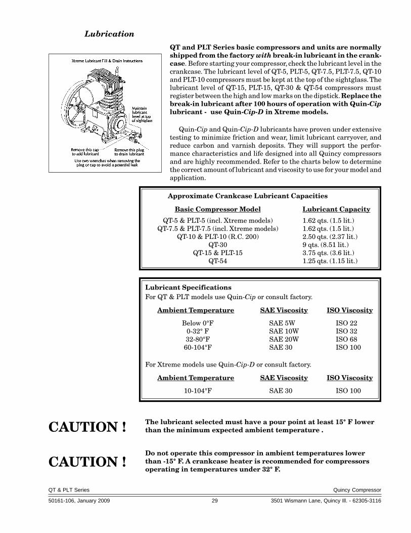
QT and PLT Series basic compressors and units are normallyshipped from the factory with break-in lubricant in the crank-case. Before starting your compressor, check the lubricant level in thecrankcase. The lubricant level of QT-5, PLT-5, QT-7.5, PLT-7.5, QT-10and PLT-10 compressors must be kept at the top of the sightglass. Thelubricant level of QT-15, PLT-15, QT-30 & QT-54 compressors mustregister between the high and low marks on the dipstick. Replace thebreak-in lubricant after 100 hours of operation with Quin-Ciplubricant - use Quin-Cip-D in Xtreme models.
Quin-Cip and Quin-Cip-D lubricants have proven under extensivetesting to minimize friction and wear, limit lubricant carryover, andreduce carbon and varnish deposits. They will support the perfor-mance characteristics and life designed into all Quincy compressorsand are highly recommended. Refer to the charts below to determinethe correct amount of lubricant and viscosity to use for your model andapplication.
Approximate Crankcase Lubricant Capacities
Basic Compressor Model Lubricant Capacity
QT-5 & PLT-5 (incl. Xtreme models) 1.62 qts. (1.5 lit.)QT-7.5 & PLT-7.5 (incl. Xtreme models) 1.62 qts. (1.5 lit.)
QT-10 & PLT-10 (R.C. 200) 2.50 qts. (2.37 lit.)QT-30 9 qts. (8.51 lit.)
QT-15 & PLT-15 3.75 qts. (3.6 lit.)QT-54 1.25 qts. (1.15 lit.)
Lubricant SpecificationsFor QT & PLT models use Quin-Cip or consult factory.
Ambient Temperature SAE Viscosity ISO Viscosity
Below 0°F SAE 5W ISO 220-32° F SAE 10W ISO 3232-80°F SAE 20W ISO 6860-104°F SAE 30 ISO 100
For Xtreme models use Quin-Cip-D or consult factory.
Ambient Temperature SAE Viscosity ISO Viscosity
10-104°F SAE 30 ISO 100
The lubricant selected must have a pour point at least 15° F lowerthan the minimum expected ambient temperature .
Do not operate this compressor in ambient temperatures lowerthan -15° F. A crankcase heater is recommended for compressorsoperating in temperatures under 32° F.
CAUTION !
CAUTION !

QT & PLT Series Quincy Compressor
50161-106, January 2009 30 3501 Wismann Lane, Quincy Ill. - 62305-3116
Pulley / Sheave Alignment & Belt Tension
Improper pulley/sheave alignment and belt tension are causes for motoroverloading, excessive vibration, and premature belt and/or bearing failure. Toprevent this from happening, check the pulley/sheave alignment and belttension on a regular basis (refer to SECTION 5, Maintenance Schedule).
Periodically inspect the motor pulley(s) and compressor sheave(s) for oil,grease, nicks or burrs. Clean or replace if necessary. Make sure they aresecurely fastened. Align the compressor sheave with the motor or engine pulley.Drive belt grooves of the pulley(s) and sheave(s) should be in line with eachother. The compressor crankshaft must be parallel to the motor or engine driveshaft.
Belt tension should be measured and adjusted to provide smooth operation.Step-by-step procedures are provided here to correctly measure and set thedrive belt tension:
Step 1) Measure the span length of the drive. (Refer to Fig. 5-1, SettingBelt Tension.)
Belt Motor Pulley RecommendedCross Dia. Range Deflection Force (lbs.)
Section (inches) Minimum Maximum
A QT-54 only 2 3B 4.6 4.0 5.9B 5.0 - 5.4 4.5 6.7B 5.6 - 6.4 5.0 7.4B 6.8 - 9.4 5.8 8.6
Pix 1152Fig. 5-1Setting Belt Tension

QT & PLT Series Quincy Compressor
50161-106, January 2009 31 3501 Wismann Lane, Quincy Ill. - 62305-3116
Step 2) Determine the amount of deflection (in inches) required to measure deflection force (inpounds) by multiplying the span length x 1/64 (.016)(i.e. 32” span length x 1/64 [.016] = 1/2”[.50] of deflec-tion required to measure deflection force).
Step 3) Lay a straightedge across the top outersurface of a drive belt from pulley to sheave.
Step 4) At the center of the span, perpendicu-lar to the belt, apply pressure to the outer surfaceof the belt with a belt tension gauge (refer to Fig.5-2, Belt Tension Gauge). Force the belt to thepredetermined deflection (refer to Step 2 above).Record the reading on the belt tension gauge andcompare to the chart following Fig 5-1. The de-flection force reading should be within the mini-mum and maximum values shown. Adjust belt(s)accordingly. New belts should be initially tensionedto the maximum value plus 33% (multiply by 1.33).
Step 5) Recheck the tension of the new beltsseveral times in the first 50 hours of operation andadjust if necessary. Thereafter, check belt tensionon a regular basis (refer to SECTION 5, Mainte-nance Schedule).
Pressure Switch Adjustment
Pressure switches provided by Quincy Compres-sor are pre-set at the factory and usually do notrequire adjustment. However, the following pro-cedures can be performed by a qualified electri-cian to adjust the pressure switch.
Step 1) Remove the pressure switch cover.
Step 2) While the compressor is running, screwthe spring loaded adjustment screw in (clockwise)
to increase the amount of air pressure required to open the switchand stop the unit. Screw the spring loaded adjustment screw out(counterclockwise) to decrease the amount of air pressure requiredto open the switch and stop the unit.
Standard pressure switches supplied by Quincy Compressor are equippedwith a fixed 20 PSIG (approx.) differential. Optional switches include bothpressure and differential adjustment capabilities.
Electric power always exists inside the pressure switch wheneverthe compressor package is connected to a power supply. Be carefulnot to touch any electrical leads when adjusting the pressureswitch.
Pix 1067Fig. 5-3 Pressure Switch
WARNING !
PRESSUREADJUSTMENT
SCREW
ELECTRICALCONTACTS
Fig. 5-2 Belt Tension Gauge Pix 1153
POCKET CLIP
SLIDING RUBBER O-RINGS
DEFLECTIONFORCE SCALE(READ DOWN)
DEFLECTIONDISTANCE
SCALE(READ UP)

QT & PLT Series Quincy Compressor
50161-106, January 2009 32 3501 Wismann Lane, Quincy Ill. - 62305-3116
Never exceed the designed pressure for the system or overload themotor beyond its Maximum Amp Draw.
* Full Load Amps x Service Factor = Maximum Amp Draw
Never assume a compressor is safe to work on just because it is notoperating. It may be in the automatic stand-by mode and mayrestart any time. Follow all safety precautions outlined in SEC-TION 5, Stopping For Maintenance.
Torquing Cylinder to Head Capscrews
Torque cylinder to head capscrews to specifications listed in the parts bookcorresponding to the Record of Change for your compressor. Then, run thecompressor for at least 1 hour. Shut the unit off and follow precautions outlinedin SECTION 5, Stopping for Maintenance. Retorque the head capscrews tosame specifications after the unit has cooled.
WARNING !
WARNING !
* Full load amps (FLA) & Service Factor can usually be found on the motor nameplate.† Reference torque spec. note in parts book corresponding to Record of Change for your compressor.

QT & PLT Series Quincy Compressor
50161-106, January 2009 33 3501 Wismann Lane, Quincy Ill. - 62305-3116
PILOT VALVE ADJUSTMENTSPILOT VALVE ADJUSTMENTSPILOT VALVE ADJUSTMENTSPILOT VALVE ADJUSTMENTSPILOT VALVE ADJUSTMENTS
All adjustments made to the pilot valve must be performed by a qualified technician. The adjustments mustbe made while the unit is operating, therefore, extreme caution must be taken while working on the unit.Observe all necessary precautions. Always use a back-up wrench and make all differential and unload pressureadjustments in very small increments (1/8 turn).
WARNING !The pressure switch and / or pilot valve are set at the factory for maximum efficiency. Adjustments to eithercomponent must be performed by a qualified technician. Exceeding the factory recommended maximum pressurewill void the warranty and may cause personal injury.
*
Setting Unload Pressure
*
Step 1. Flip the toggle to the"RUN" position asshown, or turn theknurled knob (if soequipped) counter-clockwise until itstops.
Step 2. Loosen locknut(counterclockwise). *Stabilize withback-up wrench!
Step 3. Turn clockwise to increase unload pres-sure, turn counterclockwise to decreaseunload pressure. Hold position withwrench and proceed to Step 4.
Step 4. Tighten locknut (clockwise) with wrench.* Stabilize with back-up wrench!
Setting Differential Pressure
Step 5. Loosen locknut (counterclock-wise). * Stabilize with back-upwrench!
Step 6. Turn clockwise to decrease thedifferential pressure and coun-terclockwise to increase the dif-ferential pressure. Hold posi-tion with wrench and proceedto Step 7.
Step 7. Tighten locknut (clockwise)with wrench. * Stabilize withback-up wrench!
"MANUALUNLOAD"
position(Ref.)

QT & PLT Series Quincy Compressor
50161-106, January 2009 34 3501 Wismann Lane, Quincy Ill. - 62305-3116
SECTION 6SECTION 6SECTION 6SECTION 6SECTION 6 TROUBLESHOOTINGTROUBLESHOOTINGTROUBLESHOOTINGTROUBLESHOOTINGTROUBLESHOOTING
Trouble Probable Cause
Low discharge pressure •Restricted inlet•Defective compressor valves or valve unloading mechanism•Leaks in the compressed air distribution system at fittings, connections,
etc.•Unloader pilot valve defective or set wrong•Pressure switch defective or set wrong•Drive belt slipping•Incorrect speed•Worn piston rings or loose piston•Leaking head gasket•Drain valve open•Defective pressure gauge•Excessive running clearances (refer to SECTION 2, Specifications)•Pressure relief valve leaking•Clogged intercooler•Loose compressor valves or leaking at valve gaskets•Compressor incorrectly sized for the altitude it is operating at•Piston rings not seated; allow 100 hours at full pressure
Water in the crankcase •Compressor does not run long enough to get hot and vaporize the liquids(lubricant appears milky) squeezed out of the air during compression (compressor may be too large
for application)•Incorrect or inferior grade of lubricant•System pressure leaking back through discharge valve
Rusty valves •Compressor operated too infrequentlyand/or cylinders •Compressor does not run long enough to get hot and vaporize the liquids
squeezed out of the air during compression (compressor may be too largefor application)
•Compressor not properly prepared for storage•Discharge line from compressor head is pointed upward allowing con
densation to drain back at shutdown
Excessive vibration •Incorrect speed•Compressor valves not functioning properly•Loose pulley/sheave•Motor or engine out of balance•Compressor, motor or engine not secured tightly, or tightened into a
bind•Foundation or frame inadequate•Piping inadequately supported or tightened into a bind•Excessive discharge pressure•Compressor feet may need to be leveled with shims

QT & PLT Series Quincy Compressor
50161-106, January 2009 35 3501 Wismann Lane, Quincy Ill. - 62305-3116
Trouble Probable Cause
Excessive drive belt wear •Pulley/sheave out of alignment•Belt too loose or too tight•Belt slipping•Pulley/sheave wobbling•Pulley/sheave groove damaged or rough•Incorrect belts
Low oil pressure •Oil sump strainer plugged•Excessive leakage at crankshaft seals•Low oil level•Oil pump incorrectly assembled to the bearing carrier (“o”ring not
properly located between oil pump body & bearing carrier)•Oil pressure adjusting screw not set properly•Defective oil pressure gauge
Compressor loads •Air receiver too smalland unloads excessively •Compressor valves or unloaders defective
•Excessive system leakage•Compressor operating at incorrect speed•Unloader pilot differential set too close•Pressure switch defective
Defective pressure switch •Moisture &/or oil buildup on the pressure switch diaphragm•Ruptured diaphragm•Burned contact points•Plugged air passage from the receiver to the pressure switch•Loose electrical connection
Excessive air pressure •Air pressure gauge inaccuratein air receiver •Leaks in unloader piping system
•Defective compressor head unloader•Pilot valve or pressure switch set incorrectly or defective•Pressure switch wired incorrectly•Tube to compressor head unloader plugged
Excessive •Intercooler restricted or pluggedintercooler pressure •Compressor valves in second stage broken or not functioning properly(Two stage models only) •Pilot valve or pressure switch set incorrectly or defective
•Pressure gauge defective
QT & PLT Series Quincy Compressor
50161-106, January 2009 36 3501 Wismann Lane, Quincy Ill. - 62305-3116
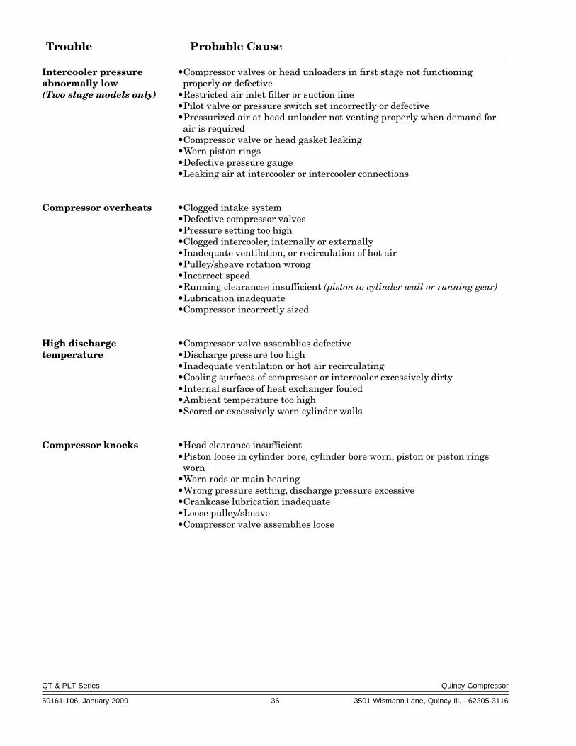
Trouble Probable Cause
Intercooler pressure •Compressor valves or head unloaders in first stage not functioningabnormally low properly or defective(Two stage models only) •Restricted air inlet filter or suction line
•Pilot valve or pressure switch set incorrectly or defective•Pressurized air at head unloader not venting properly when demand for
air is required•Compressor valve or head gasket leaking•Worn piston rings•Defective pressure gauge•Leaking air at intercooler or intercooler connections
Compressor overheats •Clogged intake system•Defective compressor valves•Pressure setting too high•Clogged intercooler, internally or externally•Inadequate ventilation, or recirculation of hot air•Pulley/sheave rotation wrong•Incorrect speed•Running clearances insufficient (piston to cylinder wall or running gear)•Lubrication inadequate•Compressor incorrectly sized
High discharge •Compressor valve assemblies defectivetemperature •Discharge pressure too high
•Inadequate ventilation or hot air recirculating•Cooling surfaces of compressor or intercooler excessively dirty•Internal surface of heat exchanger fouled•Ambient temperature too high•Scored or excessively worn cylinder walls
Compressor knocks •Head clearance insufficient•Piston loose in cylinder bore, cylinder bore worn, piston or piston rings
worn•Worn rods or main bearing•Wrong pressure setting, discharge pressure excessive•Crankcase lubrication inadequate•Loose pulley/sheave•Compressor valve assemblies loose
QT & PLT Series Quincy Compressor
50161-106, January 2009 37 3501 Wismann Lane, Quincy Ill. - 62305-3116
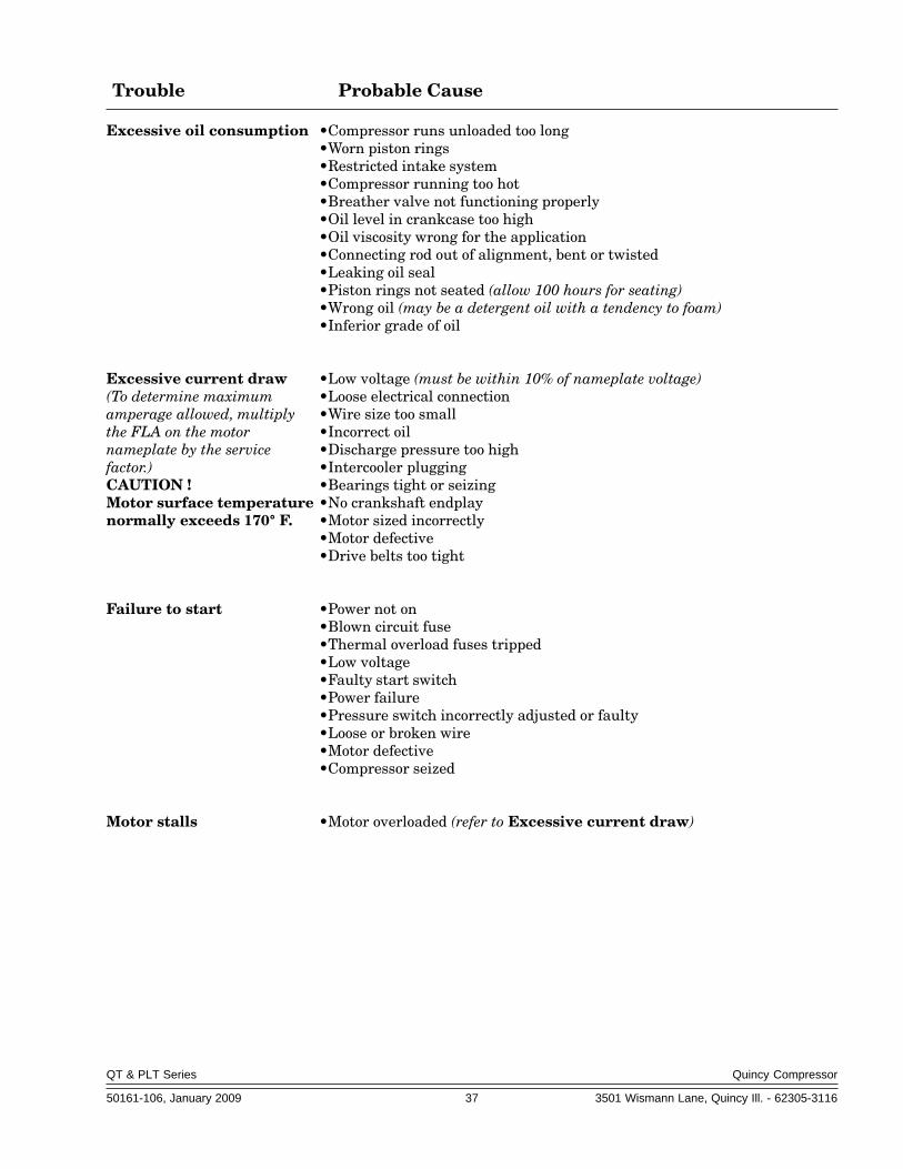
Trouble Probable Cause
Excessive oil consumption •Compressor runs unloaded too long•Worn piston rings•Restricted intake system•Compressor running too hot•Breather valve not functioning properly•Oil level in crankcase too high•Oil viscosity wrong for the application•Connecting rod out of alignment, bent or twisted•Leaking oil seal•Piston rings not seated (allow 100 hours for seating)•Wrong oil (may be a detergent oil with a tendency to foam)•Inferior grade of oil
Excessive current draw •Low voltage (must be within 10% of nameplate voltage)(To determine maximum •Loose electrical connectionamperage allowed, multiply •Wire size too smallthe FLA on the motor •Incorrect oilnameplate by the service •Discharge pressure too highfactor.) •Intercooler pluggingCAUTION ! •Bearings tight or seizingMotor surface temperature •No crankshaft endplaynormally exceeds 170° F. •Motor sized incorrectly
•Motor defective•Drive belts too tight
Failure to start •Power not on•Blown circuit fuse•Thermal overload fuses tripped•Low voltage•Faulty start switch•Power failure•Pressure switch incorrectly adjusted or faulty•Loose or broken wire•Motor defective•Compressor seized
Motor stalls •Motor overloaded (refer to Excessive current draw)

QT & PLT Series Quincy Compressor
50161-106, January 2009 38 3501 Wismann Lane, Quincy Ill. - 62305-3116
Typical QT & PLT Series Unit with Horizontal Receiver
Typical QT & PLT Series Engine Driven Unit with Horizontal Receiver
SECTION 7SECTION 7SECTION 7SECTION 7SECTION 7 REFERENCE INFORMATIONREFERENCE INFORMATIONREFERENCE INFORMATIONREFERENCE INFORMATIONREFERENCE INFORMATION
Decal Locations

QT & PLT Series Quincy Compressor
50161-106, January 2009 39 3501 Wismann Lane, Quincy Ill. - 62305-3116
Typical QT & PLT Series Unit with Vertical Receiver

QT & PLT Series Quincy Compressor
50161-106, January 2009 40 3501 Wismann Lane, Quincy Ill. - 62305-3116
Typical Xtreme Tank Mounted Unit
Typical Xtreme Base Mounted Unit
QT & PLT Series Quincy Compressor
50161-106, January 2009 41 3501 Wismann Lane, Quincy Ill. - 62305-3116
QUINCY COMPRESSORSTANDARD TERMS AND CONDITIONS
LEGAL EFFECT: Except as expressly otherwise agreed to in writing by anauthorized representative of Seller, the following terms and conditions shallapply to and form a part of this order and any additional and/or different termsof Buyer’s purchase order or other form of acceptance are rejected in advanceand shall not become a part of this order.
The rights of Buyer hereunder shall be neither assignable nor transferableexcept with the written consent of Seller.
This order may not be canceled or altered except with the written consentof Seller and upon terms which will indemnify Seller against all lossoccasioned thereby. All additional costs incurred by Seller due to changes indesign or specifications, modification of this order or revision of product mustbe paid for by Buyer.
In addition to the rights and remedies conferred upon Seller by this order,Seller shall have all rights and remedies conferred at law and in equity andshall not be required to proceed with the performance of this order if Buyeris in default in the performance of such order or of any other contract or orderwith seller.
TERMS OF PAYMENT: Unless otherwise specified in the order acknowl-edgment, the terms of payment shall be 1% 15, net forty-five (45) days aftershipment. These terms shall apply to partial as well as complete shipments.If any proceeding be initiated by or against Buyer under any bankruptcy orinsolvency law, or in the judgment of Seller the financial condition of Buyer,at the time the equipment is ready for shipment, does not justify the terms ofpayment specified, Seller reserves the right to require full payment in cashprior to making shipment. If such payment is not received within fifteen (15)days after notification of readiness for shipment, Seller may cancel the orderas to any unshipped item and require payment of its reasonable cancellationcharges.
If Buyer delays shipment, payments based on date of shipment shallbecome due as of the date when ready for shipment. If Buyer delayscompletion of manufacture, Seller may elect to require payment according topercentage of completion. Equipment held for Buyer shall be at Buyer’s riskand storage charges may be applied at the discretion of Seller.
Accounts past due shall bare interest at the highest rate lawful to contractfor but if there is no limit set by law, such interest shall be eighteen percent(18%). Buyer shall pay all cost and expenses, including reasonable attorney’sfees, incurred in collecting the same, and no claim, except claims withinSeller’s warranty of material or workmanship, as stated below, will berecognized unless delivered in writing to Seller within thirty (30) days afterdate of shipment.
TAXES: All prices exclude present and future sales, use, occupation,license, excise, and other taxes in respect of manufacture, sales or delivery, allof which shall be paid by Buyer unless included in the purchase price at theproper rate or a proper exemption certificate is furnished.
ACCEPTANCE: All offers to purchase, quotations and contracts of salesare subject to final acceptance by an authorized representative at Seller’splant.
DELIVERY: Except as otherwise specified in this quotation, delivery willbe F. O. B. point of shipment. In the absence of exact shipping instruction,Seller will use its discretion regarding best means of insured shipment. Noliability will be accepted by Seller for so doing. All transportation charges areat Buyer’s expense. Time of delivery is an estimate only and is based uponthe receipt of all information and necessary approvals. The shipping scheduleshall not be construed to limit seller in making commitments for materials orin fabricating articles under this order in accordance with Seller’s normal andreasonable production schedules.
Seller shall in no event be liable for delays caused by fires, acts of God,strikes, labor difficulties, acts of governmental or military authorities, delaysin transportation or procuring materials, or causes of any kind beyond Seller’scontrol. No provision for liquidated damages for any cause shall apply underthis order. Buyer shall accept delivery within thirty (30) days after receipt ofnotification of readiness for shipment. Claims for shortages will be deemedto have been waived if not made in writing with ten (10) days after the receiptof the material in respect of which any such shortage is claimed. Seller is not
responsible for loss or damage in transit after having received “In GoodOrder” receipt from the carrier. All claims for loss or damage in transit shouldbe made to the carrier.
TITLE & LIEN RIGHTS: The equipment shall remain personal property,regardless of how affixed to any realty or structure. Until the price (includingany notes given therefore) of the equipment has been fully paid in cash, Sellershall, in the event of Buyer’s default, have the right to repossess suchequipment.
PATENT INFRINGMENT: If properly notified and given an opportunityto do so with friendly assistance, Seller will defend Buyer and the ultimateuser of the equipment from any actual or alleged infringement of anypublished United States patent by the equipment or any part thereof furnishedpursuant hereto (other than parts of special design, construction, or manufac-ture specified by and originating with Buyer), and will pay all damages andcosts awarded by competent court in any suit thus defended or of which it mayhave had notice and opportunity to defend as aforesaid.
STANDARD WARRANTY: Seller warrants that products of its ownmanufacture will be free from defects in workmanship and materials undernormal use and service for the period specified in the product instructionmanual. Warranty for service parts will be Ninety (90) days from date offactory shipment. Electric Motors, gasoline and diesel engines, electricalapparatus and all other accessories, components and parts not manufacturedby Seller are warranted only to the extent of the original manufacturer’swarranty.
Notice of the alleged defect must be given to the Seller, in writing with allidentifying details including serial number, type of equipment and date ofpurchase within thirty (30) days of the discovery of the same during thewarranty period.
Seller’s sole obligation on this warranty shall be, at its option, to repair orreplace or refund the purchase price of any product or part thereof whichproves to be defective. If requested by Seller, such product or part thereofmust be promptly returned to seller, freight prepaid, for inspection.
Seller warrants repaired or replaced parts of its own manufacture againstdefects in materials and workmanship under normal use and service for ninety(90) days or for the remainder of the warranty on the product being repaired.
This warranty shall not apply and Seller shall not be responsible or liablefor:
(a) Consequential, collateral or special losses or damages;(b) Equipment conditions caused by fair wear and tear, abnormal condi-
tions of use, accident, neglect or misuse of equipment, improper storage ordamage resulting during shipping;
(c)Deviation from operating instructions, specifications or other specialterms of sale;
(d) Labor charges, loss or damage resulting from improper operation,maintenance or repairs made by person(s) other than Seller or Seller’sauthorized service station.
In no event shall Seller be liable for any claims whether arising from breachof contract or warranty or claims of negligence or negligent manufacture inexcess of the purchase price.
THIS WARRANTY IS THE SOLE WARRANTY OF SELLERS ANDANY OTHER WARRANTIES, WHETHER EXPRESS OR IMPLIED INLAW OR IMPLIED IN FACT, INCLUDING ANY WARRANTIES OFMERCHANTABILITY AND FITNESS FOR PARTICULAR USE AREHEREBY SPECIFICALLY EXCLUDED.
LIABILITY LIMITATIONS: Under no circumstances shall the Seller haveany liability for liquidated damages or for collateral, consequential or specialdamages or for loss of profits, or for actual losses or for loss of production orprogress of construction, whether resulting from delays in delivery or perfor-mance, breach of warranty, negligent manufacture or otherwise.
ENVIROMENTAL AND OSHA REQUIREMENTS: At the time of ship-ment of the equipment from the factory, Quincy Compressor / Ortman FluidPower will comply with the various Federal, State and local laws andregulations concerning occupational health and safety and pollution. How-ever, in the installation and operation of the equipment and other matters overwhich the seller has no control, the Seller assumes no responsibility forcompliance with those laws and regulations, whether by the way of indemnity,warranty or otherwise.
June 30, 2003

*QRD Series excluded 50253-100 mnchklst.doc
MAINTENANCE SCHEDULE CHECKLIST
Use this form to develop a routine maintenance schedule and record of performed maintenance. In the numbered columns enter the initials of the person who performed the maintenance and the date. Enter additional maintenance procedures in the spaces provided in the left hand column as needed per your application. Equipment operating under humid or dirty conditions may require shorter intervals between scheduled maintenance. The instruction manual provided with Quincy Compressor products, as well as any instructions supplied by manufacturers of supporting equipment, should be read and understood prior to performing maintenance. NOTE: Make your entries on a copy of this form. Retain this original form to make more copies in the future.
Suggested Weekly (40 hrs.) Intervals Maintenance Procedures 1 2 3 4 5 6 7 8 9 10 11 12
•manually test pressure relief valves • •clean surfaces of intercooler • •check distribution system for leaks • •check for contaminated lubricant * • •check for compressor/vacuum leaks • •
Suggested Monthly (160 hrs.) Intervals Maintenance Procedures 1 2 3
•check belt tension (if applicable) • •torque sheave fasteners (if applicable) • •change lubricant (& filter if applicable)* •


ReciprReciprReciprReciprReciprocating / Systems:ocating / Systems:ocating / Systems:ocating / Systems:ocating / Systems: 217.222.7700
Air MasterAir MasterAir MasterAir MasterAir Master 217.277.0270
E-mail:E-mail:E-mail:E-mail:E-mail: [email protected]
WWWWWebsite:ebsite:ebsite:ebsite:ebsite: quincycompressor.com
quincyairmaster.com
© 2006 Quincy Compressor, an EnPro Industries company
All Rights Reserved. Litho in U.S.A.