qos for voip at the edge - thomas' sitethomas.mangin.com/data/public/linx 65 - halfpenny - voip...
TRANSCRIPT
1
QoS for VOIP at the edge
LINX 65London
18th May 2009Richard Halfpenny
Network Engineering / OperationsExa Networks Ltd (AS30740)

2
Presentation Overview
• Introduction• VOIP overview• Quality of Service – for/against• How VOIP breaks on packet switched networks• Improving VOIP end-user experience• QoS fundamentals• QoS in service provider network• Configuration examples

3
Introduction
4
Introduction
• Exa Networks – AS30740• Specialist northern based ISP• Business and education markets• HQ based near Bradford, West Yorkshire• Present at both LINX and AMS-IX• Focus on service quality and customer
support
5
Introduction
• Scope of presentation is overview ofimplementing QoS at network edge (PE->CE)
• We typically implement on leased privatecircuits – Ethernet and Serial
• DSL a different beast (and talk!). More layersto consider – PPPoATM sessions deliveredover L2TP over IP over ATM (BT 20CN).

6
Introduction
• Exa implementing QoS on Cisco equipment atthe edge, mostly on 7301 and 7204.
• ISR’s (1841/2811) for CPE• Juniper M series in core for L3, Foundry at L2.• QoS features we use not supported on M
series without intelligent queuing PICs.– e.g. rate limiter/shaper on vlan with queues within
rate limiter• Intend to migrate fully to Juniper in future (both
L2/L3

7
VOIPOverview

8
VOIP overview
• “Talking to people over t’interwebs”• Signalling
– Call setup and tear-down• Media
– Audio stream from caller A to caller B– Audio stream from caller B to caller A

9
VOIP overview
• Signalling for call setup/teardown– Typically SIP or Cisco Skinny (SCCP)– Phone to Phone– Phone to PSTN Gateway or Session Border
Controller– Call routing– Co-ordinates codecs used for media stream
10
VOIP overview
• Media (sending process)– Typically RTP/udp– Audio (speech) waveform, amplitude of which is sampled at
constant rate X number of times per second. 8000 / 8Khz at 8bit resolution but can vary.
– Blocks of raw samples encoded in specific format (codec).Typically every 20ms or 160 samples (assuming 8Khz samplerate) but can vary depending on codec used. Codec maycompress samples to save bandwidth.
– Encoded blocks of samples encapsulated in RTP/udp packet(packetised). Sent at regular intervals, usually one encodedblock per IP packet, to receiving device. Typical packet size of200 bytes (IP+UDP+RTP headers 40 bytes, 160 bytes payload).
11
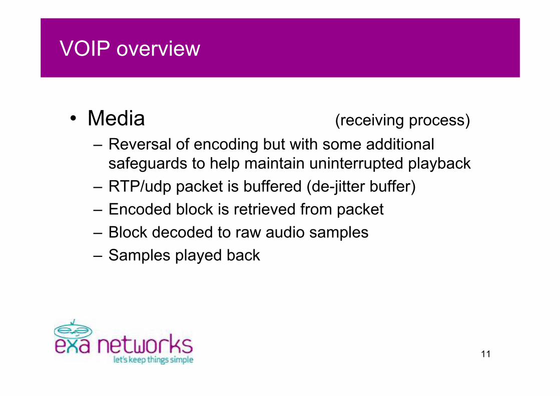
VOIP overview
• Media (receiving process)– Reversal of encoding but with some additional
safeguards to help maintain uninterrupted playback– RTP/udp packet is buffered (de-jitter buffer)– Encoded block is retrieved from packet– Block decoded to raw audio samples– Samples played back
12
Quality of ServiceFor/Against?

13
QoS – reasons to implement?
• Customers request it– Trend is to migrate towards converged data/voice
networks.• Improved perception of service provider “quality”• Competitive advantage• Can make VOIP just as reliable as TDM delivery if
implemented correctly combined with resilient network design• Turning on QoS inside a router usually doesn’t cost any
money but upgrading a circuit does• Upgrading circuit line rate won’t help.. applications can (and
will) consume any sized link to the detriment of VOIP.
14
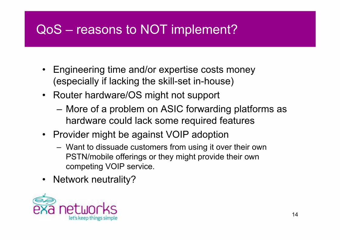
QoS – reasons to NOT implement?
• Engineering time and/or expertise costs money(especially if lacking the skill-set in-house)
• Router hardware/OS might not support– More of a problem on ASIC forwarding platforms as
hardware could lack some required features• Provider might be against VOIP adoption
– Want to dissuade customers from using it over their ownPSTN/mobile offerings or they might provide their owncompeting VOIP service.
• Network neutrality?
15
What can break VOIPon a packet switched
network?
16
VOIP - what can break on packet switched networks
• Numerous factors affect the experience ofVOIP for an end-user on a packetswitched network!– Jitter– Packet Loss– Out of order packets– Lack of bandwidth

17
VOIP - what can break on packet switched networks
• Jitter– Any variation in the delay of media packets sent from
caller A reaching caller B.– Receiving end must see packets at regular intervals.– De-jitter buffer is used at receiving end – packets
clock in to buffer at irregular intervals and clock outuniformly for decoding. Typical length 30-50ms.
– Too much jitter and the buffer becomes exhausted.Length can be increased but affects end-to-end delay.ITU G.114 recommendation for end-to-end is 150msmax – at 400ms two way conversation becomes verydifficult. Codec delays eat into this figure.

18
VOIP - what can break on packet switched networks

19
VOIP - what can break on packet switched networks

20
VOIP - what can break on packet switched networks
• Jitter– No media re-transmissions.. if playback “timeslot” for
an encoded sample block is missed or de-jitter bufferis exhausted an audio drop-out occurs.
– Small RTP packet (200 bytes) stuck behind a numberof larger data packets (1500 bytes) within interfaceoutput queue.
– Lower circuit line rate means higher serialisationdelay and packets take longer to clock onto wire.
21
VOIP - what can break on packet switched networks
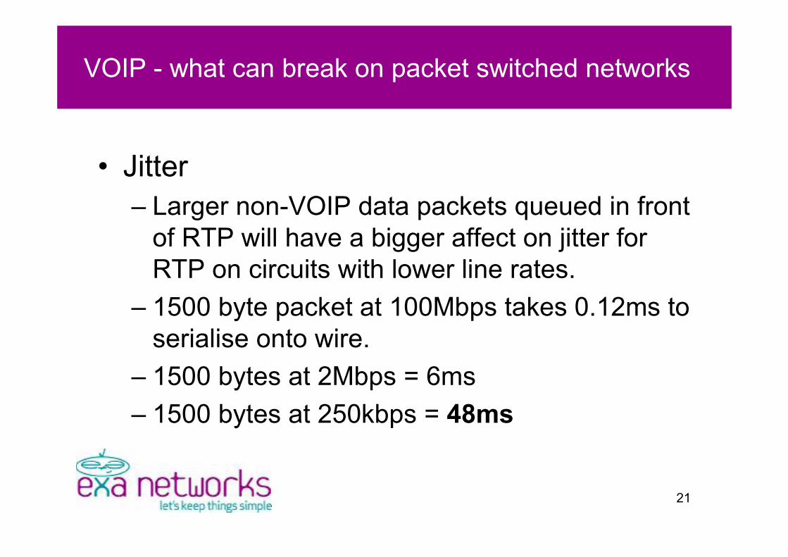
• Jitter– Larger non-VOIP data packets queued in front
of RTP will have a bigger affect on jitter forRTP on circuits with lower line rates.
– 1500 byte packet at 100Mbps takes 0.12ms toserialise onto wire.
– 1500 bytes at 2Mbps = 6ms– 1500 bytes at 250kbps = 48ms
22
VOIP - what can break on packet switched networks
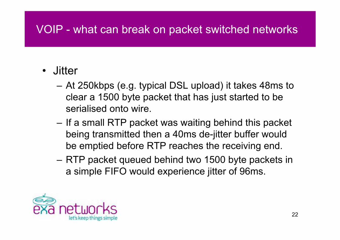
• Jitter– At 250kbps (e.g. typical DSL upload) it takes 48ms to
clear a 1500 byte packet that has just started to beserialised onto wire.
– If a small RTP packet was waiting behind this packetbeing transmitted then a 40ms de-jitter buffer wouldbe emptied before RTP reaches the receiving end.
– RTP packet queued behind two 1500 byte packets ina simple FIFO would experience jitter of 96ms.

23
VOIP - what can break on packet switched networks
• Packet loss– Interface CRC errors.– Interface output buffer exhaustion leading to tail drop.
Problematic on equipment with small buffers –microbursts not absorbed.
– No re-transmission mechanism in media stream.– Leads to break-up of audio.– Control channel sensitive to packet loss but not jitter.
24
VOIP - what can break on packet switched networks
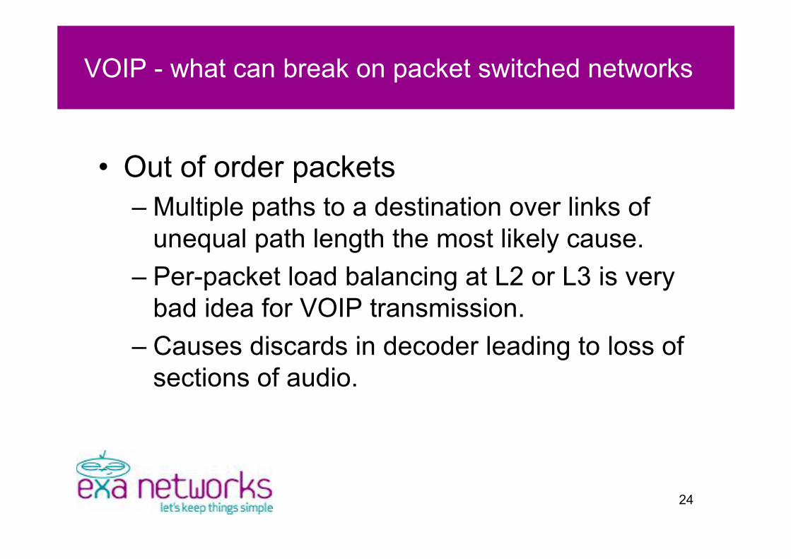
• Out of order packets– Multiple paths to a destination over links of
unequal path length the most likely cause.– Per-packet load balancing at L2 or L3 is very
bad idea for VOIP transmission.– Causes discards in decoder leading to loss of
sections of audio.
25
VOIP - what can break on packet switched networks
• Lack of bandwidth– Even the best QoS won’t shift 4Mbps of RTP
down a 1Mbps circuit!– Unless some form of CAC (Call Admission
Control) is used, a single additional 80kbpscall on a 1M circuit carrying 960kbps of RTP(12 calls) will cause audio break-up for allusers.

26
Improvingend-user experience

27
Improving end-user experience
• Ensure low jitter for media (RTP) stream• Minimise packet loss• Fix poorly implemented routing• Increase circuit bandwidth

28
Improving end-user experience
• Ensure low jitter for media (RTP) stream– Prioritise RTP over other data when queuing
for output/transmission on router interfaces.– Prefer to deploy higher line rates if possible
(reduces serialisation delay).– If using 3rd party packet switched circuits (e.g.
EoMPLS) ensure SLA’s are agreed.

29
Improving end-user experience
• Minimise packet loss– Increase output buffers if possible but this can
have a serious negative effect on jitter ifpriority queuing is not implemented.
– Ensure network monitoring systems arewatching for interface errors, CRC’s etc.

30
Improving end-user experience
• Out of order packets– For multiple links of equal cost between routers it’s
generally best practice to use load sharing thatchooses egress interface towards next hop based ona hash of destination IP address.
– 802.3ad Ethernet link aggregation.– MLPPP on lower speed bundles such as multiple E1’s
can work effectively and preserves packet orderingover links of unequal end-to-end latency.

31
Improving end-user experience
• Increase circuit bandwidth– Reduction in serialisation delay from higher line rate
can improve end-to-end delay. No need for as largede-jitter buffer.
– Customers need to be aware of limitations on howmany concurrent calls can be passed. At some pointan upgrade will be required.
– Priority queued RTP will starve bitrate available forother data, including control channel. Link fullyutilised with RTP may be useless for any best effortstraffic (e.g. http/smtp).

32
QoS Fundamentals

33
QoS Fundamentals
• Classification– Identify interesting traffic
• Marking– Mark packet with classification
• Queuing– Transmit traffic based on classification /
marking

34
QoS Fundamentals
• Classification– Identify traffic based on layer 3 packet
headers.– ACL’s to match IP protocol, port range, src/dst
IP address, etc.– Deep packet inspection devices.– Cisco NBAR (Network Based Application
Recognition)

35
QoS Fundamentals
• Classification– Agree with customer exactly what traffic to
match.– Some customer configurations may run on
non standard port numbers.
36
QoS Fundamentals
• Marking– Mark packets with information representing
classification for use later when queuing.– Layer 2 and Layer 3 handled separately.– Ethernet has CoS field but only inside .1q
frame. Marking lost if frame becomesuntagged.
– IP header has 1 byte TOS field for IPPrecedence or Differentiated Services.

37
QoS Fundamentals
• Marking– CoS and IP Precedence have 3 bits usable
giving maximum of 8 possible values.– DSCP (DiffServ CodePoint) has 6 bits usable
for 64 possible values.
– DSCP see RFC2474

38
QoS Fundamentals
• Marking– Try to do only once, as packet enters SP
network.– Use markings elsewhere in network rather
than doing a classify/mark at each router.– Overwrite markings set by customer for traffic
that obviously isn’t priority. Attacker could settheir own markings on junk traffic and flood.
39
QoS Fundamentals
• Queuing– Queue based on value contained in markings.– Priority queuing on output of interface only.– Multiple queues pointless on input as there’s
nothing you can do about packet priority atreceiving end.
– Know what your hardware is capable of!– Linecard limitations etc.

40
QoS Fundamentals
• Queuing– Software and hardware queues on most non ASIC
accelerated platforms.– Software queue by default is a single FIFO. Can be
split to form multiple queues, each being servicedwith different priority and/or policy.
– Hardware queue (aka TX Queue or TX Ring) is asmall FIFO designed to ensure there is data toserialise onto wire as soon as current frame beingtransmitted fully clears interface.

41
QoS Fundamentals
• Queuing– IOS usually automatically reduces the TX ring
to a small value when a queuing mechanismis enabled on an interface.
– Too small and link becomes under-utiliseddue to empty clock cycles between L2 frames.
– Too big and increases jitter. TX ring is a finalFIFO *after* priority/best effort/etc queues.
42
QoS Fundamentals
• Queuing– Queuing only important when there is output
congestion on an interface.– Congestion forms whenever there is more than one
packet waiting to be transmitted in the outputbuffer/queue.
– If an interface never experiences congestion thenonly a simple FIFO would be needed. This is veryunlikely however in practice due to micro trafficbursts.

43
QoS inService Provider
network

44
QoS in service provider network
• Congestion point usually at edge betweenPE-CE routers– Lower bitrate links mean higher serialisation
delay and bigger effect on jitter even whenpriority queuing is in place.
– Faster links can easily be consumed byapplications (e.g. Bittorrent) – bandwidth notthe answer so QoS needed.

45
QoS in service provider network
• Needed in core for end-to-end– QoS in core mitigates problems caused by very large micro
bursts introducing significant jitter and packet loss.– DoS conditions – mark bad traffic at edges and drop / police
everywhere based on marking rather than use IP ACL’s.– Serialisation delays generally lower due to faster line rates.
Faster interfaces usually have larger buffers but just as muchprobability of jitter being introduced.
– RTP packet stuck behind 1000 x 1500 byte packets withininterface FIFO on 1Gbps circuit adds 12ms jitter. This howeverwon’t exhaust most de-jitter buffers.
46
ConfigurationExamples

47
Configuration Examples
• Basic examples from dev hardware• Cisco IOS 12.4 SP Services• CE router is 1841 with two FastEthernet
interfaces• PE is 2811 with two FastEthernet
interfaces
48
Configuration Examples
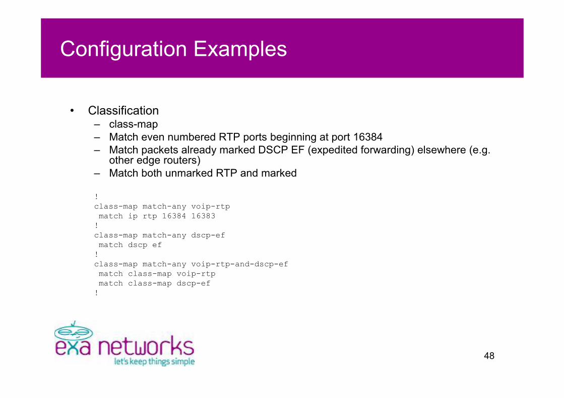
• Classification– class-map– Match even numbered RTP ports beginning at port 16384– Match packets already marked DSCP EF (expedited forwarding) elsewhere (e.g.
other edge routers)– Match both unmarked RTP and marked
!class-map match-any voip-rtpmatch ip rtp 16384 16383!class-map match-any dscp-efmatch dscp ef!class-map match-any voip-rtp-and-dscp-efmatch class-map voip-rtpmatch class-map dscp-ef!
49
Configuration Examples
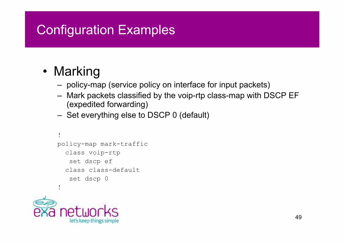
• Marking– policy-map (service policy on interface for input packets)– Mark packets classified by the voip-rtp class-map with DSCP EF
(expedited forwarding)– Set everything else to DSCP 0 (default)
!policy-map mark-traffic
class voip-rtpset dscp ef
class class-defaultset dscp 0
!

50
Configuration Examples
• Queuing– policy-map (service policy on interface for output packets)– Two queues – intended to run on a 10M interface– Low latency priority queue of upto 9M for RTP– All other traffic fair queued– 9M limit/policer on RTP to avoid starving default class of bandwidth
!policy-map customerXX-qosclass voip-rtp-and-dscp-efpriority 9000class class-defaultfair-queue
!

51
Configuration Examples
• Interface configuration on PE– 10M circuit (WES), customer commit 10M– Marking for input packets from CE– Queuing for output packets towards CE
!interface FastEthernet0/0description Customer XX via cct ref XXXX (CIR 10M)ip address 82.219.120.1 255.255.255.252speed 10duplex fullservice-policy output customerXX-qosservice-policy input mark-traffic
!
52
Configuration Examples
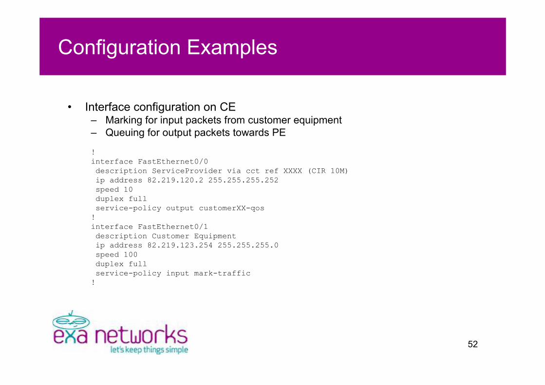
• Interface configuration on CE– Marking for input packets from customer equipment– Queuing for output packets towards PE
!interface FastEthernet0/0description ServiceProvider via cct ref XXXX (CIR 10M)ip address 82.219.120.2 255.255.255.252speed 10duplex fullservice-policy output customerXX-qos!interface FastEthernet0/1description Customer Equipmentip address 82.219.123.254 255.255.255.0speed 100duplex fullservice-policy input mark-traffic!
53
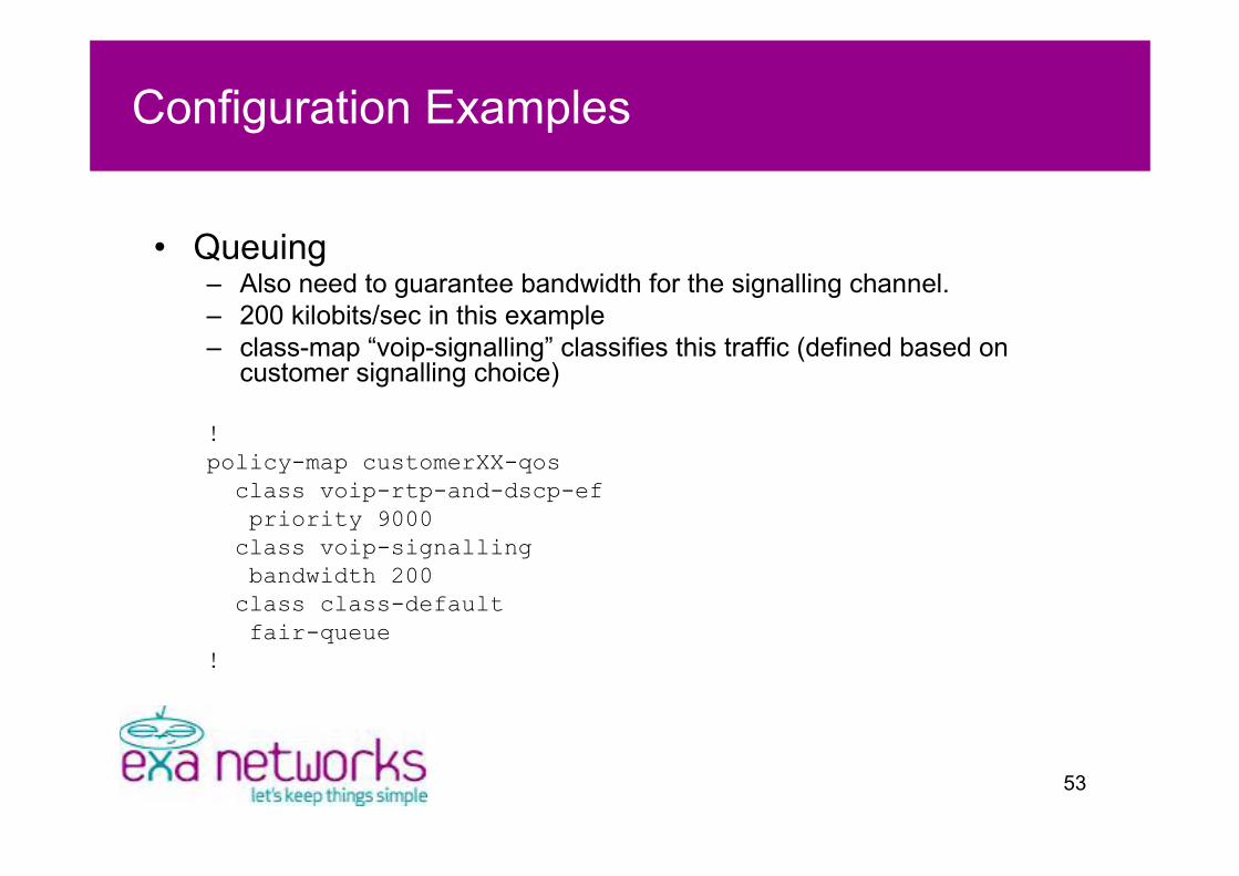
Configuration Examples
• Queuing– Also need to guarantee bandwidth for the signalling channel.– 200 kilobits/sec in this example– class-map “voip-signalling” classifies this traffic (defined based on
customer signalling choice)
!policy-map customerXX-qos
class voip-rtp-and-dscp-efpriority 9000
class voip-signallingbandwidth 200
class class-defaultfair-queue
!

54
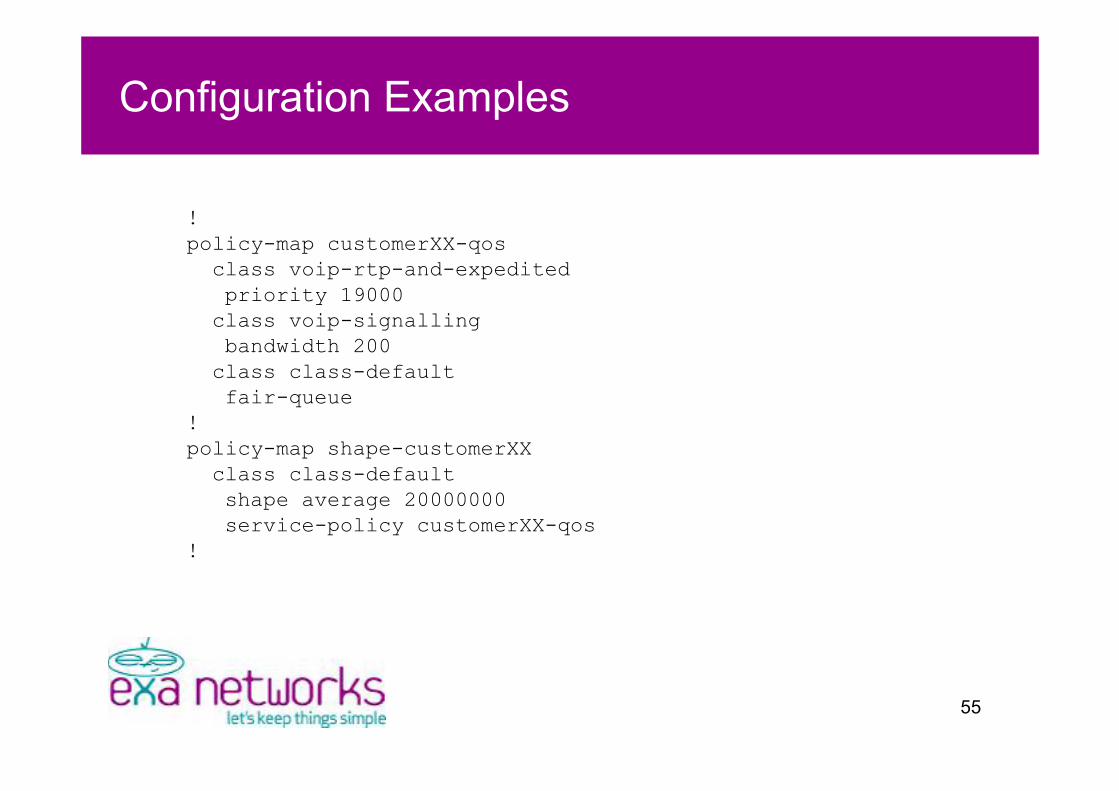
Configuration Examples
• Hierarchical policy maps– Useful for when customer fixed CIR is less
than line rate (e.g. 20M over 100M circuit)– Apply a shaper to cause congestion at CIR– Queue within shaper
55
Configuration Examples
!policy-map customerXX-qos
class voip-rtp-and-expeditedpriority 19000
class voip-signallingbandwidth 200
class class-defaultfair-queue
!policy-map shape-customerXX
class class-defaultshape average 20000000service-policy customerXX-qos
!

56
Configuration Examples
• Interface configuration on PE– 100M circuit (WES), customer commit to 20M– Output service policy changes to shape-customerXX
!interface FastEthernet0/0description Customer XX via cct ref XXXX (CIR 20M)ip address 82.219.120.1 255.255.255.252speed 100duplex fullservice-policy output shape-customerXXservice-policy input mark-traffic
!
57
Thank you foryour time
58
Questions?