qoriq dpaa primer for software architecturecache.freescale.com/files/32bit/doc/white_paper/...qoriq...
TRANSCRIPT

Freescale Semiconductor Document Number: QORIQDPAAWP White Paper Rev. 0, 06/2012
© Freescale Semiconductor, Inc., 2012. All rights reserved.
QorIQ DPAA Primer for Software Architecture
by Freescale Semiconductor, Inc.
Austin, TX
Multicore processing, or multiple execution
thread processing, introduces unique
considerations to the architecture of networking
systems, including processor load
balancing/utilization, flow order maintenance,
and efficient cache utilization. This white paper
reviews the key features, functions, and
properties enabled by the QorIQ DPAA (Data
Path Acceleration Architecture) hardware and
demonstrates how to best architect software to
leverage the DPAA hardware.
By exploring how the DPAA is configured and
leveraged in a particular application, the user
can determine which elements and features to
use. This streamlines the software development
stage of implementation by allowing
programmers to focus their technical
understanding on the elements and features that
are implemented in the system under
development, thereby reducing the overall
DPAA learning curve required to implement the
application.
Contents
1 Benefits of the DPAA ................................................. 2 2 General architectural considerations .......................... 2 3 Understanding the DPAA ........................................... 8 4 Application mapping example .................................. 31 5 Revision history ........................................................ 38
QorIQ DPAA Primer for Software Architecture, Rev. 0
2 Freescale Semiconductor
1 Benefits of the DPAA
Architecting a networking application with a multicore processor presents challenges (such as workload
balance and maintaining flow order), which are not present in a single core design. Without hardware
assistance, the software must implement techniques that are inefficient and cumbersome, reducing the
performance benefit of multiple cores. To address workload balance and flow order challenges, the
DPAA determines and separates ingress flows then manages the temporary, permanent, or semi-
permanent flow-to-core affinity. The DPAA also provides a work priority scheme, which ensures
ingress critical flows are addressed properly and frees software from the need to implement a queuing
mechanism on egress. As the hardware determines which core will process which packet, performance
is boosted by direct cache warming/stashing as well as by providing biasing for core-to-flow affinity,
which ensures that flow-specific data structures can remain in the core’s cache.
By understanding how the DPAA is leveraged in a particular design, the system architect can map out
the application to meet the performance goals and to utilize the DPAA features to leverage any legacy
application software that may exist. Once this application map is defined, the architect can focus on
more specific details of the implementation.
2 General architectural considerations
2.1 Multicore design considerations
As the need for processing capability has grown, the only practical way to increase the performance on a
single silicon part is to increase the number of general purpose processing cores (CPUs). However,
many legacy designs run on a single processor; introducing multiple processors into the system creates
special considerations, especially for a networking application.
Most networking applications are split between data and control plane tasks. In general, control plane
tasks manage the system within the broad network of equipment. While the control plane may process
control packets between systems, the control plane process is not involved in the bulk processing of the
data traffic. This task is left to the data plane processing task or program.
The general flow of the data plane program is to receive data traffic (in general, packets or frames),
process or transform the data in some way and then send the packets to the next hop or device in the
network. In many cases, the processing of the traffic depends on the type of traffic. In addition, the
traffic usually exists in terms of a flow, a stream of traffic where the packets are related. A simple
example could be a connection between two clients that, at the packet level, is defined by the source and
destination IP address. Typically, multiple flows are interleaved on a single interface port; the number
of flows per port depends on the interface bandwidth as well as on the bandwidth and type of flows
involved.
QorIQ DPAA Primer for Software Architecture, Rev. 0
Freescale Semiconductor 3
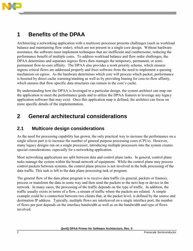
2.2 Parse/classification software offload
The DPAA provides intelligence within the IO subsection of the SoC (system-on-chip) to split traffic
into user-defined queues. One benefit is that the intelligence used to divide the traffic can be leveraged
at a system level.
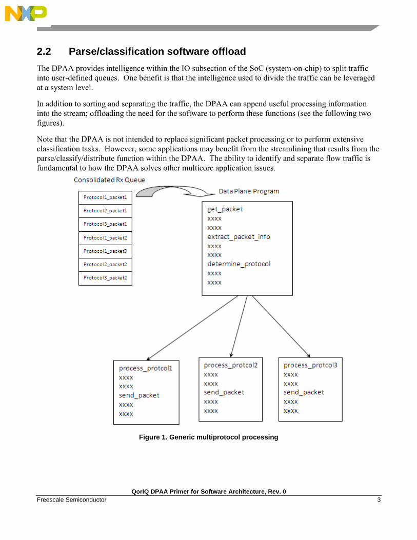
In addition to sorting and separating the traffic, the DPAA can append useful processing information
into the stream; offloading the need for the software to perform these functions (see the following two
figures).
Note that the DPAA is not intended to replace significant packet processing or to perform extensive
classification tasks. However, some applications may benefit from the streamlining that results from the
parse/classify/distribute function within the DPAA. The ability to identify and separate flow traffic is
fundamental to how the DPAA solves other multicore application issues.
Figure 1. Generic multiprotocol processing
QorIQ DPAA Primer for Software Architecture, Rev. 0
4 Freescale Semiconductor
Figure 2. Hardware-sorted protocol flow
2.3 Flow order considerations
In most networking applications, individual traffic flows through the system require that the egress
packets remain in the order in which they are received. In a single processor core system, this
requirement is easy to implement. As long as the data plane software follows a run-to-completion
model on a per-packet basis, the egress order will match the ingress packet order. However, if multiple
processors are implemented in a true symmetrical multicore processing (SMP) model in the system, the
egress packet flow may be out of order with respect to the ingress flow. This may be caused when
multiple cores simultaneously process packets from the same flow.

QorIQ DPAA Primer for Software Architecture, Rev. 0
Freescale Semiconductor 5
Even if the code flow is identical, factors such as cache hits/misses, DRAM page hits/misses, interrupts,
control plane and OS tasks can cause some variability in the processing path, allowing egress packets to
“pass” within the same flow, as shown in this figure.
Figure 3. Multicore flow reordering
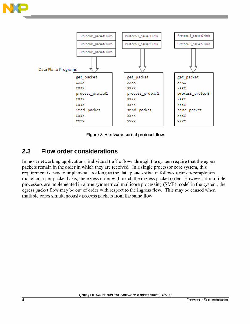
For some applications, it is acceptable to reorder the flows from ingress to egress. However, most
applications require that order is maintained. When no hardware is available to assist with this ordering,
the software must maintain flow order. Typically, this requires additional code to determine the
sequence of the packet currently being processed, as well as a reference to a data structure that maintains
order information for each flow in the system. Because multiple processors need to access and update
this state information, access to this structure must be carefully controlled, typically by using a lock
mechanism that can be expensive with regard to program cycles and processing flow (see Figure 4). One
of goals of the DPAA architecture is to provide the system designer with hardware to assist with packet
ordering issues.
QorIQ DPAA Primer for Software Architecture, Rev. 0
6 Freescale Semiconductor
Figure 4. Implementing order in software
2.4 Managing flow-to-core affinity
In a multicore networking system, if the hardware configuration always allows a specific core to process
a specific flow then the binding of the flow to the core is described as providing flow affinity. If a
specific flow is always processed by a specific processor core then for that flow the system acts like a
single core system. In this case, flow order is preserved because there is a single thread of operation
processing the flow; with a run-to-completion model, there is no opportunity for egress packets to be
reordered with respect to ingress packets.
Another benefit of a specific flow being affined to a core is that the cache local to that core (L1 and
possibly L2, depending on the specific core type) is less likely to miss when processing the packets
because the core’s data cache will not fetch flow state information for flows to which it is not affined.
Also, because multiple processing entities have no need to access the same individual flow state
information, the system need not lock the access to the individual flow state data. The DPAA offers
several options to define and manage flow-to-core affinity.

QorIQ DPAA Primer for Software Architecture, Rev. 0
Freescale Semiconductor 7
Figure 5. Managing flow-to-core affinity
Many networking applications require intensive, repetitive algorithms to be performed on large portions
of the data stream(s). While software in the processor cores could perform these algorithms, specific
hardware offload engines often better address specific algorithms. Cryptographic and pattern matching
accelerators are examples of this in the QorIQ family. These accelerators act as standalone hardware
elements that are fed blocks or streams of data, perform the required processing, and then provide the
output in a separate (or perhaps overwritten) data block within the system. The performance boost is
significant for tasks that can be done by these hardware accelerators as compared to a software
implementation.

QorIQ DPAA Primer for Software Architecture, Rev. 0
8 Freescale Semiconductor
In DPAA-equipped SoCs, these offload engines exist as peers to the cores and IO elements, and they use
the same queuing mechanism to obtain and transfer data. The details of the specific processing
performed by these offload engines is beyond the scope of this document; however, it is important to
determine which of these engines will be leveraged in the specific application. The DPAA can then be
properly defined to implement the most efficient configuration/definition of the DPAA elements.
3 Understanding the DPAA
3.1 DPAA goals
The following provides a brief overview of the DPAA elements in order to contextualize the application
mapping activities. For more details on the DPAA architecture, see the QorIQ Data Path Acceleration
Architecture (DPAA) Reference Manual.
The primary goals of the DPAA are as follows:
To provide intelligence within the IO portion of the SoC.
To route and manage the processing work associated with traffic flows.
To simplify the ordering and load balance concerns associated with multicore processing.
The DPAA achieves these goals by inspecting and separating ingress traffic into Frame Queues (FQs).
In general, the intent is to define a flow or set of flows as the traffic in a particular FQ. The FQs are
associated to a specific core or set of cores via a channel. Within the channel definition, the FQs can be
prioritized among each other using the Work Queue (WQ) mechanism. The egress flow is similar to the
ingress flow. The processors place traffic on a specific FQ, which is associated to a particular physical
port via a channel. The same priority scheme using WQs exists on egress, allowing higher priority
traffic to pass lower priority traffic on egress without software intervention.
3.2 DPAA elements
3.2.1 FMan overview
The FMan inspects traffic, splits it into FQs on ingress, and sends traffic from the FQs to the interface
on egress. On ingress traffic, the FMan is configured to determine the traffic split required by the PCD
(Parse, Classify, Distribute) function. This allows the user to decide how he wants to define his traffic:
typically, by flows or classes of traffic. The PCD can be configured to route all traffic on one port to a
single queue or with a higher level of complexity where large numbers of queues are defined and
managed. The PCD can identify traffic based on the specific content of the incoming packets (usually
within the header) or packet reception rates (policing).
The parse function is used to identify which fields within the data frame determine the traffic split. The
fields used may be defined by industry standards, or the user may employ a programmable soft parse
feature to accommodate proprietary field (typically header) definition(s). The results of the parse
function may be used directly to determine the frame queue; or, the contents of the fields selected by the
QorIQ DPAA Primer for Software Architecture, Rev. 0
Freescale Semiconductor 9
parse function may be used as a key to select the frame queue. The parse function employs a
programmed mask to allow the use of selected fields.
The resultant key from the parse function may be used to assign traffic to a specific queue based on a
specific exact match definition of fields in the header. Alternatively, a range of queues can be defined
either by using the resultant key directly (if there are a small number of bits in the key) or by performing
a hash of the key to use a large number of bits in the flow identifier and create a manageable number of
queues.
The FMan also provides a policer function, which is rate-based and allows the user to mark or drop a
specific frame that exceeds a traffic threshold. The policing is based on a two-rate, three-color marking
algorithm (RFC2698). The sustained and peak rates as well as the burst sizes are user-configurable.
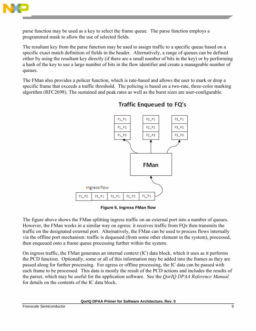
Figure 6. Ingress FMan flow
The figure above shows the FMan splitting ingress traffic on an external port into a number of queues.
However, the FMan works in a similar way on egress: it receives traffic from FQs then transmits the
traffic on the designated external port. Alternatively, the FMan can be used to process flows internally
via the offline port mechanism: traffic is dequeued (from some other element in the system), processed,
then enqueued onto a frame queue processing further within the system.
On ingress traffic, the FMan generates an internal context (IC) data block, which it uses as it performs
the PCD function. Optionally, some or all of this information may be added into the frames as they are
passed along for further processing. For egress or offline processing, the IC data can be passed with
each frame to be processed. This data is mostly the result of the PCD actions and includes the results of
the parser, which may be useful for the application software. See the QorIQ DPAA Reference Manual
for details on the contents of the IC data block.
QorIQ DPAA Primer for Software Architecture, Rev. 0
10 Freescale Semiconductor
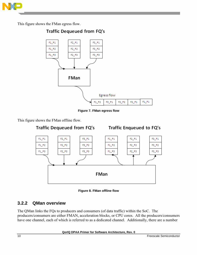
This figure shows the FMan egress flow.
Figure 7. FMan egress flow
This figure shows the FMan offline flow.
Figure 8. FMan offline flow
3.2.2 QMan overview
The QMan links the FQs to producers and consumers (of data traffic) within the SoC. The
producers/consumers are either FMAN, acceleration blocks, or CPU cores. All the producers/consumers
have one channel, each of which is referred to as a dedicated channel. Additionally, there are a number
QorIQ DPAA Primer for Software Architecture, Rev. 0
Freescale Semiconductor 11
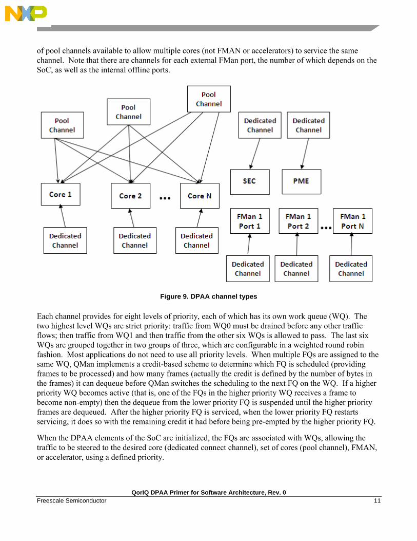
of pool channels available to allow multiple cores (not FMAN or accelerators) to service the same
channel. Note that there are channels for each external FMan port, the number of which depends on the
SoC, as well as the internal offline ports.
Figure 9. DPAA channel types
Each channel provides for eight levels of priority, each of which has its own work queue (WQ). The
two highest level WQs are strict priority: traffic from WQ0 must be drained before any other traffic
flows; then traffic from WQ1 and then traffic from the other six WQs is allowed to pass. The last six
WQs are grouped together in two groups of three, which are configurable in a weighted round robin
fashion. Most applications do not need to use all priority levels. When multiple FQs are assigned to the
same WQ, QMan implements a credit-based scheme to determine which FQ is scheduled (providing
frames to be processed) and how many frames (actually the credit is defined by the number of bytes in
the frames) it can dequeue before QMan switches the scheduling to the next FQ on the WQ. If a higher
priority WQ becomes active (that is, one of the FQs in the higher priority WQ receives a frame to
become non-empty) then the dequeue from the lower priority FQ is suspended until the higher priority
frames are dequeued. After the higher priority FQ is serviced, when the lower priority FQ restarts
servicing, it does so with the remaining credit it had before being pre-empted by the higher priority FQ.
When the DPAA elements of the SoC are initialized, the FQs are associated with WQs, allowing the
traffic to be steered to the desired core (dedicated connect channel), set of cores (pool channel), FMAN,
or accelerator, using a defined priority.

QorIQ DPAA Primer for Software Architecture, Rev. 0
12 Freescale Semiconductor
Figure 10. Prioritizing work
3.2.2.1 Portals
A single portal exists for each non-core DPAA producer/consumer (FMAN, SEC, and PME). This is a
data structure internal to the SoC that passes data directly to/from the consumer’s direct connect
channel.
Software portals are associated with the processor cores and are, effectively, data structures that the
cores use to pass (enqueue) packets to or receive (dequeue) packets from the channels associated with
that portal (core). Each SoC has at least as many software portals as there are cores. Software portals
are the interface through which the DPAA provides the data processing workload for a single thread of
execution.

QorIQ DPAA Primer for Software Architecture, Rev. 0
Freescale Semiconductor 13
The portal structure consists of the following:
The Dequeue Response Ring (DQRR) determines the next packet to be processed.
The Enqueue Command Ring (EQCR) sends packets from the core to the other elements.
The Message Ring (MR) notifies the core of the action (for example, attempted dequeue rejected,
and so on).
The Management command and response control registers
Figure 11. Processor core portal
On ingress, the DQRR acts as a small buffer of incoming packets to a particular core. When a section of
software performs a get packet type operation, it gets the packet from a pointer provided as an entry in
the DQRR for the specific core running that software. Note that the DQRR consolidates all potential
channels that may be feeding frames to a particular core. There are up to 16 entries in each DQRR.
Each DQRR entry contains:
a pointer to the packet to be processed,
an identifier of the frame queue from which the packet originated,
a sequence number (when configured),
and additional FMan-determined data (when configured).
When configured for push mode, QMan attempts to fill the DQRR from all the potential incoming
channels. When configured in pull mode, QMan only adds one DQRR entry when it is told to by the
requesting core. Pull mode may be useful in cases where the traffic flows must be very tightly
controlled; however, push mode is normally considered the preferred mode for most applications.
QorIQ DPAA Primer for Software Architecture, Rev. 0
14 Freescale Semiconductor
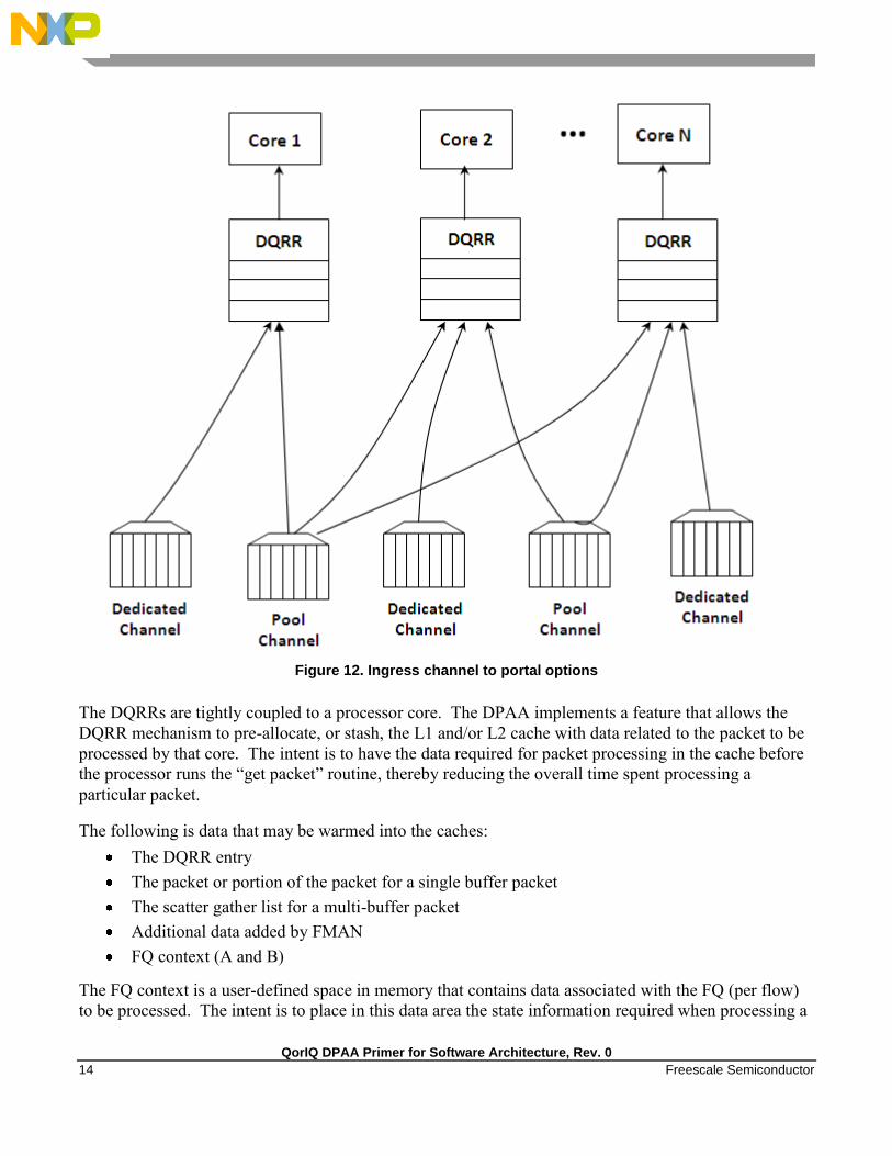
Figure 12. Ingress channel to portal options
The DQRRs are tightly coupled to a processor core. The DPAA implements a feature that allows the
DQRR mechanism to pre-allocate, or stash, the L1 and/or L2 cache with data related to the packet to be
processed by that core. The intent is to have the data required for packet processing in the cache before
the processor runs the “get packet” routine, thereby reducing the overall time spent processing a
particular packet.
The following is data that may be warmed into the caches:
The DQRR entry
The packet or portion of the packet for a single buffer packet
The scatter gather list for a multi-buffer packet
Additional data added by FMAN
FQ context (A and B)
The FQ context is a user-defined space in memory that contains data associated with the FQ (per flow)
to be processed. The intent is to place in this data area the state information required when processing a

QorIQ DPAA Primer for Software Architecture, Rev. 0
Freescale Semiconductor 15
packet for this flow. The FQ context is part of the FQ definition, which is performed when the FQ is
initialized.
The cache warming feature is enabled by configuring the capability and some definition of the FQs and
QMan at system initialization time. This can provide a significant performance boost and requires little
to no change in the processing flow. When defining the system architecture, it is highly recommended
that the user enable this feature and consider how to maximize its impact.
Figure 13. Cache warming options
In addition to getting packet information from the DQRR, the software also manages the DQRR by
indicating which DQRR entry it will consume next. This is how the QMan determines when the DQRR
(portal) is ready to process more frames. Two basic options are provided. In the first option, the
software can update the ring pointer after one or several entries have been consumed. By waiting to
indicate the consumption of multiple frames, the performance impact of the write doing this is
minimized. The second option is to use the discrete consumption acknowledgment (DCA) mode. This
QorIQ DPAA Primer for Software Architecture, Rev. 0
16 Freescale Semiconductor
mode allows the consumption indication to be directly associated with a frame enqueue operation from
the portal (that is, after the frame has been processed and is on the way to the egress queue). This
tracking of the DQRR Ring Pointer CI (Consumer Index) helps implement frame ordering by ensuring
that QMan does not dequeue a frame from the same FQ (or flow) to a different core until the processing
is completed.
3.2.2.2 Queue schedule options
The primary communication path between QMan and the processor cores is the portal memory structure.
QMan uses this interface to schedule the frames to be processed on a per-core basis. For a dedicated
channel, the process is straightforward: the QMan places an entry in the DQRR for the portal (processor)
of the dedicated channel and dequeues the frame from an FQ to the portal. To do this, QMan
determines, based on the priority scheme (previously described) for the channel, which frame should be
processed next and then adds an entry to the DQRR for the portal associated with the channel.
When configured for push mode, once the portal requests QMan to provide frames for processing,
QMan provides frames until halted. When the DQRR is full and more frames are destined for the portal,
QMan waits for an empty slot to become available in the DQRR and then adds more entries (frames to
be processed) as slots become available.
When configured for pull mode, the QMan only adds entries to the DQRR at the direct request of the
portal (software request). The command to the QMan that determines if a push or pull mode is
implemented and tells QMan to provide either one or from one to three (up to three if there are that
many frames to be dequeued) frames at a time. This is a tradeoff of smaller granularity (for one frame
only) versus memory access consolidation (if the up to three frames option is selected).
When the system is configured to use pool channels, a portal may get frames from more than one
channel and a channel may provide frames (work) to more than one portal (core). QMan dequeues
frames using the same mechanism described above (updating DQRR) and QMan also provides for some
specific scheduling options to account for the pool channel case in which multiple cores may process the
same channel.
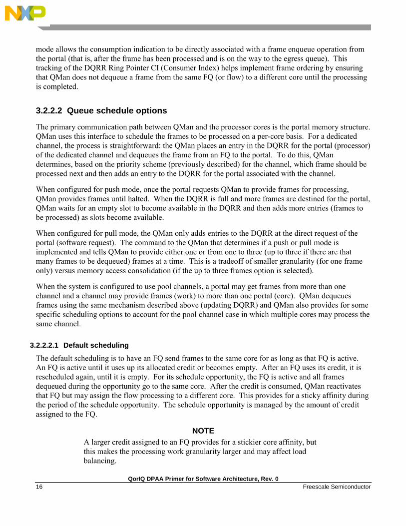
3.2.2.2.1 Default scheduling
The default scheduling is to have an FQ send frames to the same core for as long as that FQ is active.
An FQ is active until it uses up its allocated credit or becomes empty. After an FQ uses its credit, it is
rescheduled again, until it is empty. For its schedule opportunity, the FQ is active and all frames
dequeued during the opportunity go to the same core. After the credit is consumed, QMan reactivates
that FQ but may assign the flow processing to a different core. This provides for a sticky affinity during
the period of the schedule opportunity. The schedule opportunity is managed by the amount of credit
assigned to the FQ.
NOTE
A larger credit assigned to an FQ provides for a stickier core affinity, but
this makes the processing work granularity larger and may affect load
balancing.

QorIQ DPAA Primer for Software Architecture, Rev. 0
Freescale Semiconductor 17
Figure 14. Default scheduling
3.2.2.2.2 Hold active scheduling
With the hold active option, when the QMan assigns an FQ to a particular core, that FQ is affined to that
core until it is empty. Even after the FQ’s credit is consumed, when it is rescheduled with the next
schedule opportunity, the frames go to the same core for processing. This effectively makes the flow-to-
core affinity stickier than the default case, ensuring the same flow is processed by the same core for as
long as there are frames queued up for processing. Because the flow-to-core affinity is not hard-wired
as in the dedicated channel case, the software may still need to account for potential order issues.
However, because of flow-to-core biasing, the flow state data is more likely to remain in L1 or L2
cache, increasing hit rates and thus improving processing performance. Because of the specific QMan
implementation, only four FQs may be in held active state at a given time.

QorIQ DPAA Primer for Software Architecture, Rev. 0
18 Freescale Semiconductor
Figure 15. Hold active scheduling
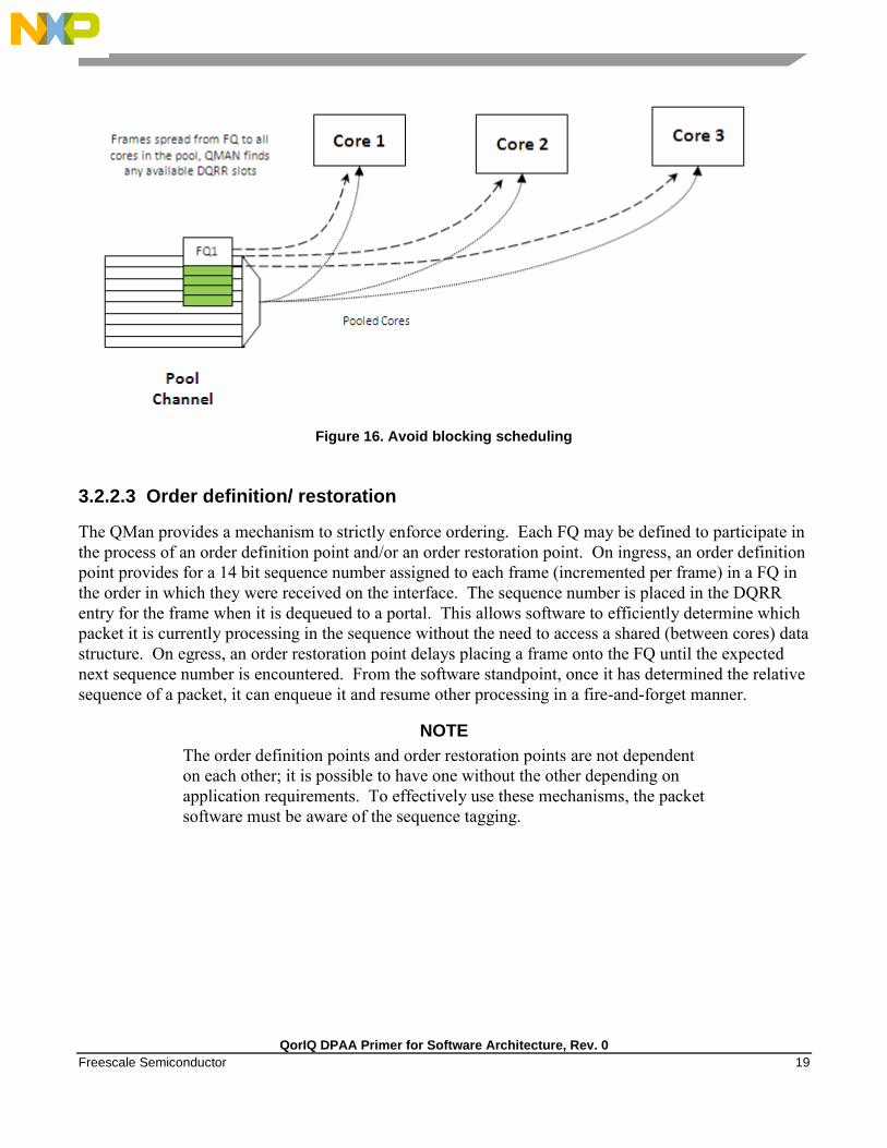
3.2.2.2.3 Avoid blocking scheduling
QMan can also be scheduled in the avoid blocking mode, which is mutually exclusive to hold active. In
this mode, QMan schedules frames for an FQ to any available core in the pool channel. For example, if
the credit allows for three frames to be dequeued, the first frame may go to core 1. But, when that
dequeue fills core 1’s DQRR, QMan finds the next available DQRR entry in any core in the pool. With
avoid blocking mode there is no biasing of the flow to core affinity. This mode is useful if a particular
flow either has no specific order requirements or the anticipated processing required for a single flow is
expected to consume more than one core’s worth of processing capability.
Alternatively, software can bypass QMan scheduling and directly control the dequeue of frame
descriptors from the FQ. This mode is implemented by placing the FQ in parked state. This allows
software to determine precisely which flow will be processed (by the core running the software).
However, it requires software to manage the scheduling, which can add overhead and impact
performance.
QorIQ DPAA Primer for Software Architecture, Rev. 0
Freescale Semiconductor 19
Figure 16. Avoid blocking scheduling
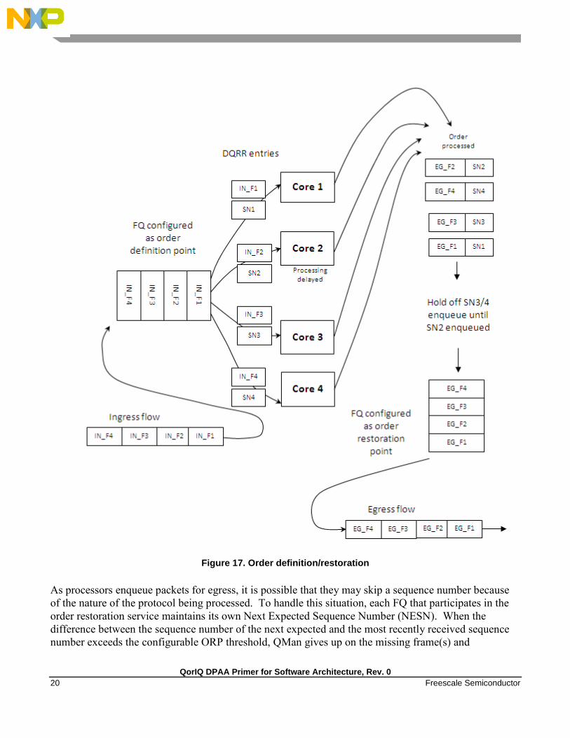
3.2.2.3 Order definition/ restoration
The QMan provides a mechanism to strictly enforce ordering. Each FQ may be defined to participate in
the process of an order definition point and/or an order restoration point. On ingress, an order definition
point provides for a 14 bit sequence number assigned to each frame (incremented per frame) in a FQ in
the order in which they were received on the interface. The sequence number is placed in the DQRR
entry for the frame when it is dequeued to a portal. This allows software to efficiently determine which
packet it is currently processing in the sequence without the need to access a shared (between cores) data
structure. On egress, an order restoration point delays placing a frame onto the FQ until the expected
next sequence number is encountered. From the software standpoint, once it has determined the relative
sequence of a packet, it can enqueue it and resume other processing in a fire-and-forget manner.
NOTE
The order definition points and order restoration points are not dependent
on each other; it is possible to have one without the other depending on
application requirements. To effectively use these mechanisms, the packet
software must be aware of the sequence tagging.
QorIQ DPAA Primer for Software Architecture, Rev. 0
20 Freescale Semiconductor
Figure 17. Order definition/restoration
As processors enqueue packets for egress, it is possible that they may skip a sequence number because
of the nature of the protocol being processed. To handle this situation, each FQ that participates in the
order restoration service maintains its own Next Expected Sequence Number (NESN). When the
difference between the sequence number of the next expected and the most recently received sequence
number exceeds the configurable ORP threshold, QMan gives up on the missing frame(s) and

QorIQ DPAA Primer for Software Architecture, Rev. 0
Freescale Semiconductor 21
autonomously advances the NESN to bring the skew within threshold. This causes any deferred
enqueus that are currently held in the ORP link list to become unblocked and immediately enqueue them
to their destination FQ. If the “skipped” frame arrives after this, the ORP can be configured to reject or
immediately enqueu the late arriving frame.
3.2.3 BMan overview
The BMan block manages the data buffers in memory. Processing cores, FMan, SEC and PME all may
get a buffer directly from the BMan without additional software intervention. These elements are also
responsible for releasing the buffers back to the pool when the buffer is no longer in use. Typically, the
FMan directly acquires a buffer from the BMan on ingress. When the traffic is terminated in the system,
the core generally releases the buffer. When the traffic is received, processed, and then transmitted, the
same buffer may be used throughout the process. In this case, the FMan may be configured to release
the buffer automatically, when the transmit completes.
The BMan also supports single or multi-buffer frames. Single buffer frames generally require the
adequately defined (or allocated) buffer size to contain the largest data frame and minimize system
overhead. Multi-buffer frames potentially allow better memory utilization, but the entity passed
between the producers/consumers is a scatter-gather table (that then points to the buffers within the
frame) rather than the pointer to the entire frame, which adds an extra processing requirement to the
processing element.
The software defines pools of buffers when the system is initialized. The BMan unit itself manages the
pointers to the buffers provided by the software and can be configured to interrupt the software when it
reaches a condition where the number of free buffers is depleted (so that software may provide more
buffers as needed).
3.3 Using the DPAA to handle order
The DPAA helps address packet order issues that may occur as a result of running an application in a
multiple processor environment. And there are several ways to leverage the DPAA to handle flow order
in a system. The order preservation technique maps flows such that a specific flow always executes on a
specific processor core. For this case, the individual flow will not have multiple execution threads and
the system will run much like a single core system. This option generally requires less impact to legacy,
single-core software but may not effectively utilize all the processing cores in the system because it
requires using a dedicated channel to the processors. The FMan PCD can be configured to either
directly match a flow to a core or to use the hashing to provide traffic spreading that offers a permanent
flow-to-core affinity.
If the application must use pool channels to balance the processing load then the software must be more
involved in the ordering. The software can make use of the order restoration point function in QMan,
which requires the software to manage a sequence number for frames enqueued on egress.
Alternatively, the software can be implemented to maintain order by biasing the stickiness of flow
affinity with default or hold active scheduling; lock contention and cache misses can be biased to
increase performance.

QorIQ DPAA Primer for Software Architecture, Rev. 0
22 Freescale Semiconductor
If there are no order requirements then load balancing can be achieved by associating the non-ordered
traffic to a pool of cores.
NOTE
All of these techniques may be implemented simultaneously on the same
SoC; as long as the flow definition is precise enough to split the traffic
types, it is simply a matter of proper defining the FQs and associating
them to the proper channels in the system.
3.3.1 Using the exact match flow definition to preserve order
The simplest technique for preserving order is to route the ingress traffic of an individual flow to a
particular core. For the particular flow in question, the system appears as a legacy, single-core
programming model and, therefore, has minimal impact on the structure of the software. In this case,
the flow definition determines the core affinity of a flow.

QorIQ DPAA Primer for Software Architecture, Rev. 0
Freescale Semiconductor 23
Figure 18. Direct flow-to-core mapping (order preserved)
This technique is completely deterministic: the DPAA forces specific flows to a specific processor, so it
may be easier to determine the performance assuming the ingress flows are completely understood and
well defined. Notice that a particular processor core may become overloaded with traffic while another
sits idle for increasingly random flow traffic rates.
To implement this sort of scheme, the FMan must be configured to exactly match fields in the traffic
stream. This approach can only be used for a limited number of total flows before the FMan’s internal
resources are consumed.
In general, this sort of hard-wired approach should be reserved for either critical out-of-band traffic or
for systems with a small number of flows that can benefit from the highly deterministic nature of the
processing.

QorIQ DPAA Primer for Software Architecture, Rev. 0
24 Freescale Semiconductor
3.3.2 Using hashing to distribute flows across cores
The FMan can be configured to extract data from a field or fields within the data frame, build a key from
that, and then hash the resultant key into a smaller number. This is a useful technique to handle a larger
number of flows while ensuring that a particular flow is always associated with a particular core. An
example is to define a flow as an IPv4 source + IPv4 destination address. Both fields together
constitute 64 bits, so there are 264
possible combinations for the flow in that definition. The FMan then
uses a hash algorithm to compress this into a manageable number of bits. Note that, because the hash
algorithm is consistent, packets from a particular flow always go to the same FQ. By utilizing this
technique, the flows can be spread in a pseudo-random, consistent (per flow) manner to a smaller
number of FQs. For example, hashing the 64 bits down to 2 bits spreads the flows among four queues.
Then these queues can be assigned to four separate cores by using a dedicated channel; effectively, this
appears as a single-core implementation to any specific flow.
This spreading technique works best with a large number of possible flows to allow the hash algorithm
to evenly spread the traffic between the FQs. In the example below, when the system is only expected
to have eight flows at a given time, there is a good chance the hash will not assign exactly two flows per
FQ to evenly distribute the flows between the four cores shown. However, when the number of flows
handled is in the hundreds, the odds are good that the hash will evenly spread the flows for processing.

QorIQ DPAA Primer for Software Architecture, Rev. 0
Freescale Semiconductor 25
Figure 19. Simple flow distribution via hash (order preserved)
To optimize cache warming, the total number of hash buckets can be increased with flow-to-core
affinity maintained. When the number of hash values is larger than the number of expected flows at a
given time, it is likely though not guaranteed that each FQ will contain a single flow. For most
applications, the penalty of a hash collision is two or more flows within a single FQ. In the case of
multiple flows within a single FQ, the cache warming and temporary core affinity benefits are reduced
unless the flow order is maintained per flow.
Note that there are 24 bits architected for the FQ ID, so there may be as many as 16 million FQs in the
system. Although this total may be impractical, this does allow for the user to define more FQs than
expected flows in order to reduce the likelihood of a hash collision; it also allows flexibility in assigning
FQID’s in some meaningful manner. It is also possible to hash some fields in the data frame and
concatenate other parse results, possibly allowing a defined one-to-one flow to FQ implementation
without hash collisions.

QorIQ DPAA Primer for Software Architecture, Rev. 0
26 Freescale Semiconductor
Figure 20. Using hash to assign one flow per FQ (order preserved and cache stashing effective)
3.3.3 Pool channel considerations
So far, the techniques discussed in this white paper have involved assigning specific flows to the same
core to ensure that the same core always processes the same flow or set of flows, thereby preserving
flow order. However, depending on the nature of the flows being processed (that is, variable frame
sizes, difficulty efficiently spreading due to the nature of the flow contents, and so on), this may not
effectively balance the processing load among the cores. Alternatively, a user may employ a pool
channel approach where multiple cores may pool together to service a specific set of flows. This
alternative approach allows potentially better processing balance, but increases the likelihood that
packets may be processed out of order allowing egress packets to pass ingress packets. When the
application does not require flows to be processed in order, the pool channel approach allows the easiest
method for balancing the processing load. When a pool channel is used and order is required, the

QorIQ DPAA Primer for Software Architecture, Rev. 0
Freescale Semiconductor 27
software must maintain order. The hardware order preservation may be used by the software to
implement order without requiring locked access to shared state information. When the system uses a
software lock to handle order then the default scheduling and hold active scheduling tends to minimize
lock contention.
Figure 21. Using pool channel to balance processing
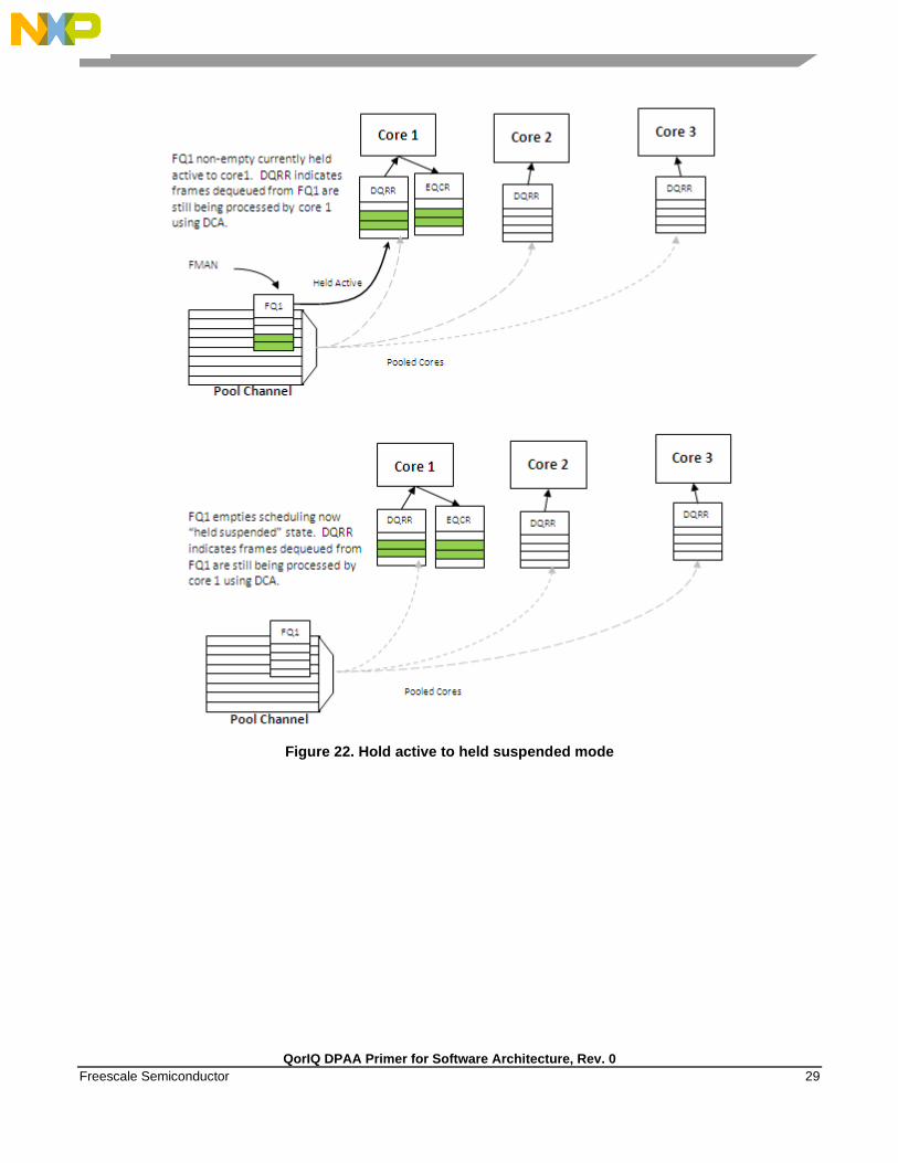
3.3.4 Order preservation using hold active scheduling and DCA mode
As shown in the examples above, order is preserved as long as two or more cores never process frames
from the same flow at the same time. This can also be accomplished by using hold active scheduling
along with discrete consumption acknowledgment (DCA) mode associated with the DQRR. Although
flow affinity may change for an FQ with hold active scheduling when the FQ is emptied, if the new

QorIQ DPAA Primer for Software Architecture, Rev. 0
28 Freescale Semiconductor
work (from frames received after the FQ is emptied) is held off until all previous work completes, then
the flow will not be processed by multiple cores simultaneously, thereby preserving order.
When the FQ is emptied, QMan places the FQ in hold suspended state, which means that no further
work for that FQ is enqueued to any core until all previously enqueued work is completed. Because
DCA mode effectively holds off the consumption notification (from the core to QMan) until the
resultant processed frame is enqueued for egress, this implies processing is completely finished for any
frames in flight to the core. After all the in-flight frames have been processed, QMan reschedules the
FQ to the appropriate core.
NOTE
After the FQ is empty and when in hold active mode, the affinity is not
likely to change. This is because the indication of “completeness” from
the core currently processing the flow frees up some DQRR slots that
could be used by QMan when it restarts enqueuing work for the flow. The
possibility of the flow-to-core affinity changing when the FQ empties is
only discussed as a worst case possibility with regards to order
preservation.
QorIQ DPAA Primer for Software Architecture, Rev. 0
Freescale Semiconductor 29
Figure 22. Hold active to held suspended mode

QorIQ DPAA Primer for Software Architecture, Rev. 0
30 Freescale Semiconductor
Figure 23. Held suspended to hold active mode
3.4 Congestion management
From an overall system perspective, there are multiple potential overflow conditions to consider. The
maximum number of frames active in the system (the number of frames in flight) is determined by the
amount of memory allocated to the Packed Frame Queue Descriptors (PQFD’s). Each PQFD is 64 bytes
and can identify up to three frames, so the total number of frames that can be identified by the PQFDs is
equal to the amount of memory allocated for PQFD space divided by 64 bytes (per entry) multiplied by
three (frames per entry).
A pool of buffers may deplete in BMan. This depends on how many buffers have been assigned by
software for BMan. BMan may raise an interrupt to request more buffers when in a depleted state for a
given pool; the software can manage the congestion state of the buffer pools in this manner.

QorIQ DPAA Primer for Software Architecture, Rev. 0
Freescale Semiconductor 31
In addition to these high-level system mechanisms, congestion management may also be identified
specific to the FQs. A number of FQs can be grouped together to form a congestion group (up to 256
congestion groups per system for most DPAA SoCs). These FQs need not be on the same channel. The
system may be configured to indicate congestion either by consider the aggregate number of bytes
within the FQ’s in the congestion group or by the aggregate number of frames within the congestion
group. The frame count option is useful when attempting to manage the number of buffers in a buffer
pool as they are used by a particular core or group of cores. The byte count is useful to manage the
amount of system memory used by a particular core or group of cores.
When the total number of frames/bytes within the frames in the congestion group exceeds the set
threshold, subsequent enqueues to any of the FQs in the group are rejected; in general, the frame is
dropped. For the congestion group mechanism, the decision to reject is defined by a programmed
weighted random early discard (WRED) algorithm programmed when the congestion group is defined.
In addition, a specific FQ can be set to a particular maximum allowable depth (in bytes); after the
threshold is reached enqueue attempts will be rejected. This is a maximum threshold: there is no
WRED algorithm for this mechanism. Note that, when the FQ threshold is not set, a specific FQ may
fill until some other mechanism (because it’s part of a congestion group or system PQFD depletion or
BMAN depletion) prevents the FQ from getting frames. Typically, FQs within a congestion group are
expected to have a maximum threshold set for each FQ in the group to ensure a single queue does not
get stuck and unfairly consume the congestion group. Note that, when an FQ does not have a queue
depth set and/or is not a part of a congestion group, the FQ has no maximum depth. It would be possible
for a single queue to have all the frames in the system, until the PQFD space or the buffer pool is
exhausted.
4 Application mapping example
4.1 Processor core assignment
The first step in application mapping is to determine how much processing capability is required for
tasks that may be partitioned separately. For example, consider a typical networking application with a
set of distinct control and data plane functionality. Assigning two cores to perform control plane tasks
and six cores to perform data plane tasks may be a reasonable partition in an eight-core device. When
initially identifying the SoC required for the application, along with the number of cores and frequencies
required, the designer makes some performance assumptions based on previous designs and/or
applicable benchmark data.
4.2 Define flows
Next, define what flows will be in the system. Key considerations for flow definition include the
following:
Total number of flows expected at a given time within the system
Desired flow-to-core affinity, ingress flow destination
QorIQ DPAA Primer for Software Architecture, Rev. 0
32 Freescale Semiconductor
Processor load balancing
Frame sizes (may be fixed or variable)
Order preservation requirement
Traffic priority relative to the flows
Expected bandwidth requirement of specific flows or class of flows
Desired congestion handling
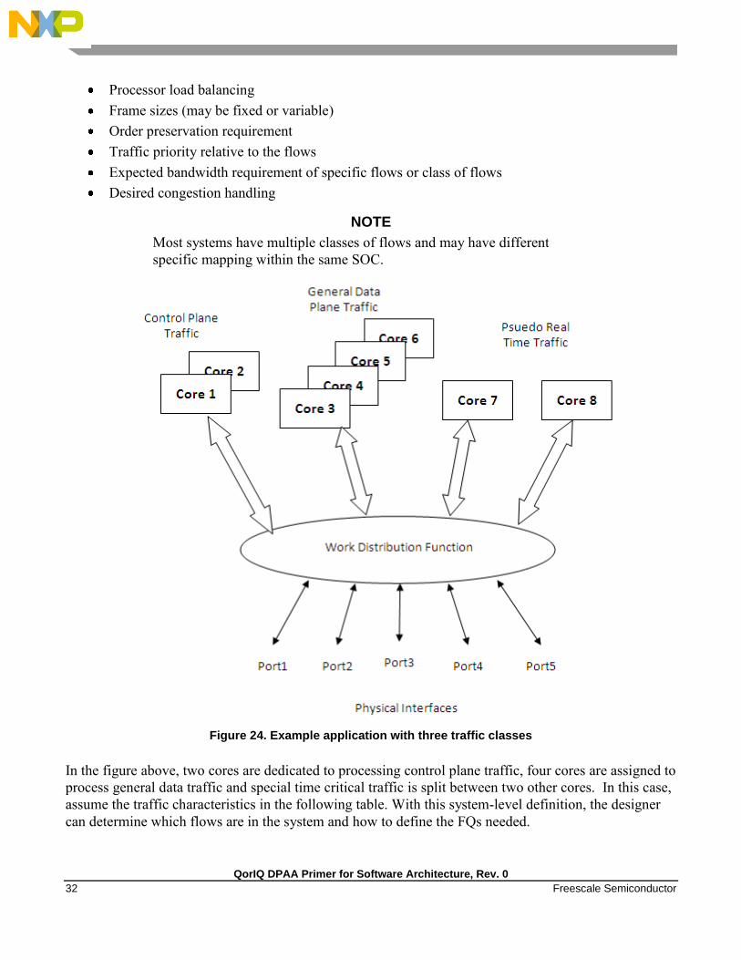
NOTE
Most systems have multiple classes of flows and may have different
specific mapping within the same SOC.
Figure 24. Example application with three traffic classes
In the figure above, two cores are dedicated to processing control plane traffic, four cores are assigned to
process general data traffic and special time critical traffic is split between two other cores. In this case,
assume the traffic characteristics in the following table. With this system-level definition, the designer
can determine which flows are in the system and how to define the FQs needed.
QorIQ DPAA Primer for Software Architecture, Rev. 0
Freescale Semiconductor 33
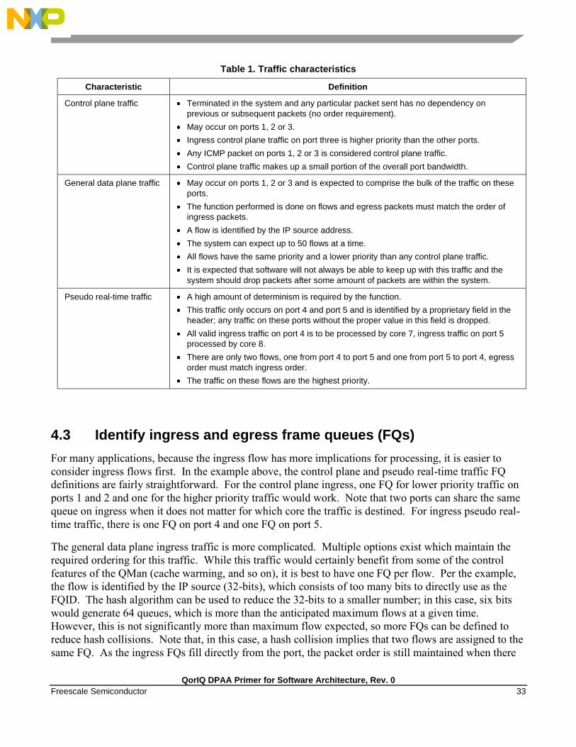
Table 1. Traffic characteristics
Characteristic Definition
Control plane traffic Terminated in the system and any particular packet sent has no dependency on
previous or subsequent packets (no order requirement).
May occur on ports 1, 2 or 3.
Ingress control plane traffic on port three is higher priority than the other ports.
Any ICMP packet on ports 1, 2 or 3 is considered control plane traffic.
Control plane traffic makes up a small portion of the overall port bandwidth.
General data plane traffic
May occur on ports 1, 2 or 3 and is expected to comprise the bulk of the traffic on these
ports.
The function performed is done on flows and egress packets must match the order of
ingress packets.
A flow is identified by the IP source address.
The system can expect up to 50 flows at a time.
All flows have the same priority and a lower priority than any control plane traffic.
It is expected that software will not always be able to keep up with this traffic and the
system should drop packets after some amount of packets are within the system.
Pseudo real-time traffic
A high amount of determinism is required by the function.
This traffic only occurs on port 4 and port 5 and is identified by a proprietary field in the
header; any traffic on these ports without the proper value in this field is dropped.
All valid ingress traffic on port 4 is to be processed by core 7, ingress traffic on port 5
processed by core 8.
There are only two flows, one from port 4 to port 5 and one from port 5 to port 4, egress
order must match ingress order.
The traffic on these flows are the highest priority.
4.3 Identify ingress and egress frame queues (FQs)
For many applications, because the ingress flow has more implications for processing, it is easier to
consider ingress flows first. In the example above, the control plane and pseudo real-time traffic FQ
definitions are fairly straightforward. For the control plane ingress, one FQ for lower priority traffic on
ports 1 and 2 and one for the higher priority traffic would work. Note that two ports can share the same
queue on ingress when it does not matter for which core the traffic is destined. For ingress pseudo real-
time traffic, there is one FQ on port 4 and one FQ on port 5.
The general data plane ingress traffic is more complicated. Multiple options exist which maintain the
required ordering for this traffic. While this traffic would certainly benefit from some of the control
features of the QMan (cache warming, and so on), it is best to have one FQ per flow. Per the example,
the flow is identified by the IP source (32-bits), which consists of too many bits to directly use as the
FQID. The hash algorithm can be used to reduce the 32-bits to a smaller number; in this case, six bits
would generate 64 queues, which is more than the anticipated maximum flows at a given time.
However, this is not significantly more than maximum flow expected, so more FQs can be defined to
reduce hash collisions. Note that, in this case, a hash collision implies that two flows are assigned to the
same FQ. As the ingress FQs fill directly from the port, the packet order is still maintained when there

QorIQ DPAA Primer for Software Architecture, Rev. 0
34 Freescale Semiconductor
is a collision (two flows into one FQ). However, having two flows in the same FQ tends to minimize
the impact of cache warming. There may be other possibilities to refine the definition of flows to ensure
a one-to-one mapping of flows to FQs (for example, concatenating other fields in the frame) but for this
example assume that an 8 bit hash (256 FQs) minimizes the likelihood of two flows in the FQ to an
acceptable level.
Consider the case in which, on ingress, there is traffic that does not match any of the intended flow
definitions. The design can handle these by placing unidentifiable packets into a separate garbage FQ or
by simply having the FMan discard the packets.
On egress control traffic, because the traffic may go out on three different ports, three FQs are required.
For the egress pseudo real-time traffic, there is one queue for each port as well.
For the egress data plane traffic, there are multiple options. When the flows are pinned to a specific
core, it might be possible to simply have one queue per port. In this case, the cores would effectively be
maintaining order. However, for this example, assume that the system uses the order definition/order
restoration mechanism previously described. In this case, the system needs to define an FQ for each
egress flow. Note that, since software is managing this, there is no need for any sort of hash algorithm
to spread the traffic; the cores will enqueue to the FQ associated with the flow. When there are no more
than 50 flows in the system at one time, and number of egress flows per port is unknown, the system
could define 50 FQs for each port when the DPAA is initialized.
4.4 Define PCD configuration for ingress FQs
This step involves defining how the FMan splits the incoming port traffic into the FQs. In general, this
is accomplished using the PCD (Parse, Classify, Distribute) function and results in specific traffic
assigned to a specific FQID. Fields in the incoming packet may be used to identify and split the traffic
as required. For this key optimization case, the user must determine the correct field. The example is as
follows:
For the ingress control traffic, the ICMP protocol identifier is the selector or key. If the traffic is
from ports 1 or 2 then that traffic goes to one FQID. If it is from port 3, the traffic goes to a
different FQID because this needs to be separated and given a higher priority than the other two
ports.
For the ingress data plane traffic, the IP source field is used to determine the FQID. The PCD is
then configured to hash the IP source to 8 bits, which will generate 256 possible FQs. Note that
this is the same, regardless of whether the packet came from ports 1, 2, or 3.
For the ingress pseudo real-time traffic, the PCD is configured to check for the proprietary
identifier. If there is a match then the traffic goes to an FQID based on the ingress port. If there
is no match then the incoming packet is discarded. Also, the soft parser needs to be
configured/programmed to locate the proprietary identifier.
Note that the FQID number itself can be anything (within the 24 bits to define the FQ). To maintain
meaning, use a numbering scheme to help identify the type of traffic. For the example, define the
following ingress FQIDs:
High priority control: FQID 0x100

QorIQ DPAA Primer for Software Architecture, Rev. 0
Freescale Semiconductor 35
Low priority control: FQID 0x200
General data plane: FQID 0x1000 – 0x10FF
Pseudo real-time traffic: FQID 0x2000 (port 4), FQID 0x2100 (port 5)
The specifics for configuring the PCDs are described in the DPAA Reference Manual and in the
Software Developer Kit (SDK) used to develop the software.
4.5 Define ingress FQ/WQ/channel configuration
For each class of traffic in the system, the FQs must be defined together with both the channel and the
WQ to which they are associated. The channel association affines to a specific processor core while the
WQ determines priority. Consider the following by class of traffic:
The control traffic goes to a pool of two cores with priority given to traffic on port 3.
The general data plane traffic goes to a pool of 4 cores.
The pseudo real-time traffic goes to two separate cores as a dedicated channel.
Note that, when the FQ is defined, in addition to the channel association, other parameters may be
configured. In the application example, the FQs from 1000 to 10FF are all assigned to the same
congestion group; this is done when the FQ is initialized. Also, for these FQs it is desirable to limit the
individual FQ length; this would also be configured when the FQ is initialized.
Because the example application is going to use order definition/order restoration mode, this setting
needs to be configured for each FQ in the general data plane traffic (FQID 0x1000-0x10FF). Note that
order is not required for the control plane traffic and that order is preserved in the pseudo real-time
traffic because the ingress traffic flows are mapped to specific cores.
QMan configuration considerations include the congestion management and pool channel scheduling. A
congestion group must be defined as part of QMan initialization. (Note that the FQ initialization is
where the FQ is bound to a congestion group.) This is where the total number of frames and the discard
policy of the congestion group are defined. Also, consider the QMan scheduling for pool channels. In
this case, the default of temporarily attaching an FQ to a core until the FQ is empty will likely work best.
This tends to keep the caches current, especially for the general data plane traffic on cores 3-6.

QorIQ DPAA Primer for Software Architecture, Rev. 0
36 Freescale Semiconductor
Figure 25. Ingress application map
4.6 Define egress FQ/WQ/channel configuration
For egress, the packets still flow through the system using the DPAA, but the considerations are
somewhat different. Note that each external port has its own dedicated channel; therefore, to send traffic
out of a specific port, the cores enqueue a frame to an FQ associated with the dedicated channel for that
port. Depending on the priority level required, the FQ is associated with a specific work queue.
For the example, the egress configuration is as follows:
For control plane traffic, there needs to be separate queues for each port this traffic may use.
These FQs must be assigned to a WQ that is higher in priority then the WQ used for the data

QorIQ DPAA Primer for Software Architecture, Rev. 0
Freescale Semiconductor 37
plane traffic. The example shown includes a strict priority (over the data plane traffic) for ports
1 and 2 with the possibility of WRED with the data plane traffic on port 3.
Because the example assumes that the order restoration facility in the FQs will be utilized, there
must be one egress FQ for each flow. The initial system assumptions are for up to 50 flows of
this type; however, the division by port is unknown, the FQs can be assigned so that there are at
least 50 for each port. Note that FQs can be added when the flow is discovered or they can be
defined at system initialization time.
For the pseudo real-time traffic, per the initial assumptions, core 7 sends traffic out of port 4 and
core 8 sends traffic out of port 5. As the flows are per core, the order is preserved because of this
mapping. These are assigned to WQ2, which allows definition for even higher priority traffic (to
WQ1) or lower priority traffic for future definition on these ports.
As stated before, the FQIDs can be whatever the user desires and should be selected to help keep track
of what type of traffic the FQ’s are associated. For this example:
Control traffic for ports 1, 2, 3 are FQID 300, 400, 500 respectively.
Data plane traffic for ports 1, 2, 3 are FQID 3000-303F, 4000-403F, and 5000-503F respectively,
this provides for 64 FQ’s per port on egress.
The pseudo real-time traffic uses FQID 6000 for port 4 and 7000 for port 5.
Because this application makes use of the order restoration feature, an order restoration point must be
defined for each data plane traffic flow. Also, congestion management on the FQs may be desirable.
Consider that the data plane traffic may come in on multiple ports but may potentially be consolidated
such that is egresses out a single port. In this case, more traffic may be attempted to be enqueued to a
port than the port interface rate may allow, which may cause congestion. To manage this possibility,
three congestion groups can be defined each containing all the FQs on each of the three ports that may
have the control plus data plane traffic. As previously discussed, it may be desirable to set the length of
the individual FQs to further manage this potential congestion.

QorIQ DPAA Primer for Software Architecture, Rev. 0
38 Freescale Semiconductor
Figure 26. Egress application map
5 Revision history
This table provides a revision history for this white paper.
Table 2. Revision history
Rev. number Date Substantive change
0 05/2012 Initial release
Document Number: QORIQDPAAWP
Rev. 0
06/2012
How to Reach Us:
Home Page:
freescale.com
Web Support:
freescale.com/support
Information in this document is provided solely to enable system and software implementers to use implementers to use Freescale products. There are no express or implied copyright licenses granted hereunder to design or fabricate any integrated circuits based on the information in this document.
Freescale reserves the right to make changes without further notice to any products herein. Freescale makes no warranty, representation, or guarantee regarding the suitability of its products for any particular purpose, nor does Freescale assume any liability arising out of the application or use of any product or circuit, and specifically disclaims any and all liability, including without limitation consequential or incidental damages. “Typical” parameters that may be provided in Freescale data sheets and/or specifications can and do vary in different applications, and actual performance may vary over time. All operating parameters, including “typicals,” must be validated for each customer application by customer’s technical experts. Freescale does not convey any license under its patent rights nor the rights of others. Freescale sells products pursuant to standard terms and conditions of sale, which can be found at the following address: http://www.reg.net/v2/webservices/Freescale/Docs/TermsandConditions.htm.
Freescale, the Freescale logo, and QorIQ are trademarks of Freescale Semiconductor, Inc. Reg. U.S. Pat. & Tm. Off. CoreNet is a trademark of Freescale Semiconductor, Inc. All other product or service names are the property of their respective owners. The Power Architecture and Power.org word marks and the Power and Power.org logos and related marks are trademarks and service marks licensed by Power.org.
© Freescale Semiconductor, Inc. 2012. All rights reserved.