qlci displacement with inductionfiles.ctctcdn.com/2a65254c001/951e4f1e-8ed9-4d52-a5d4-31...4...
TRANSCRIPT

QLCI Displacement with Inductionfor Classroom HVAC Applications
1/7.2/US/1
Trox USA, Inc. Telephone 770-569-14334305 Settingdown Circle Facsmile 770-569-1435Cumming, Georgia 30028 www.troxusa.comUSA e-mail: [email protected]

2
Contents
General Features 3
Displacement Ventilation Fundamentals 4
Displacement with Induction 8
Classroom Design Issues 12
Range of Application 13
Heat Gains in Stratified Environments 14
Thermal Comfort in Stratified Environments 15
Airflow Determination for Stratified Systems 17
High Latent Load Applications 18
Air Handling Unit Considerations 19
Classroom Heating Considerations 20
Condensation Prevention 21
Piping and Ductwork Requirements 22
Terminal Installation 23
Dimensional Information 24
Performance and Selection Information 30
Design Procedures 40
Design and Selection Examples 42
Suggested Specifications 46
Ordering Information 47
The creation and maintenance of a quiet and healthy learning environment is the greatest challenge facing designers of educational facilities today. Numerous studies identify equipment noise as a major obstacle inhibiting the learning process in elementary and middleschool environments. Many schools in operation today useHVAC technologies that result in classroom NC levels of 40to 45. As they attempt to communicate above these resi-dent noise levels, teachers are suffering from throat andrespiratory ailments that result in lost time.
The recently adopted ANSI Standard S12.60-2002 calls fora maximum (one-hour average) A-weighted background noise level of 35dB. This equates to an NClevel of about 27.
ASHRAE Standard 62.1-2004 Ventilation for AcceptableAir Quality mandates that classrooms be supplied a
minimum outdoor airflow of 15 CFM per person during alloccupied periods. Many schools do not adhere to minimum ventilation requirements stipulated by theStandard because of the costs of attainment. Others thatdo comply introduce noisy equipment directly into theclassroom in an effort get direct access to outside air.
QLCI terminals are designed to provide air quality and acoustical performance similar to that of conventionaldisplacement systems, but are specifically designed foroperation in North American climates. They are fitted witha series of air injection nozzles that allow the supply of primary air at conventional temperatures (50 to 54ºF) to theterminal. These nozzles induce room air through a heattransfer (cooling and/or heating) coil to recondition the airprior to its mixing with the primary jets. The result is a constant volume (variable temperature) displacement supply of air to the classroom.
Special Note: QLCI terminals are intended for use in HVAC systems described by this catalog and covered under U.S. Patent 7,013,969.
3
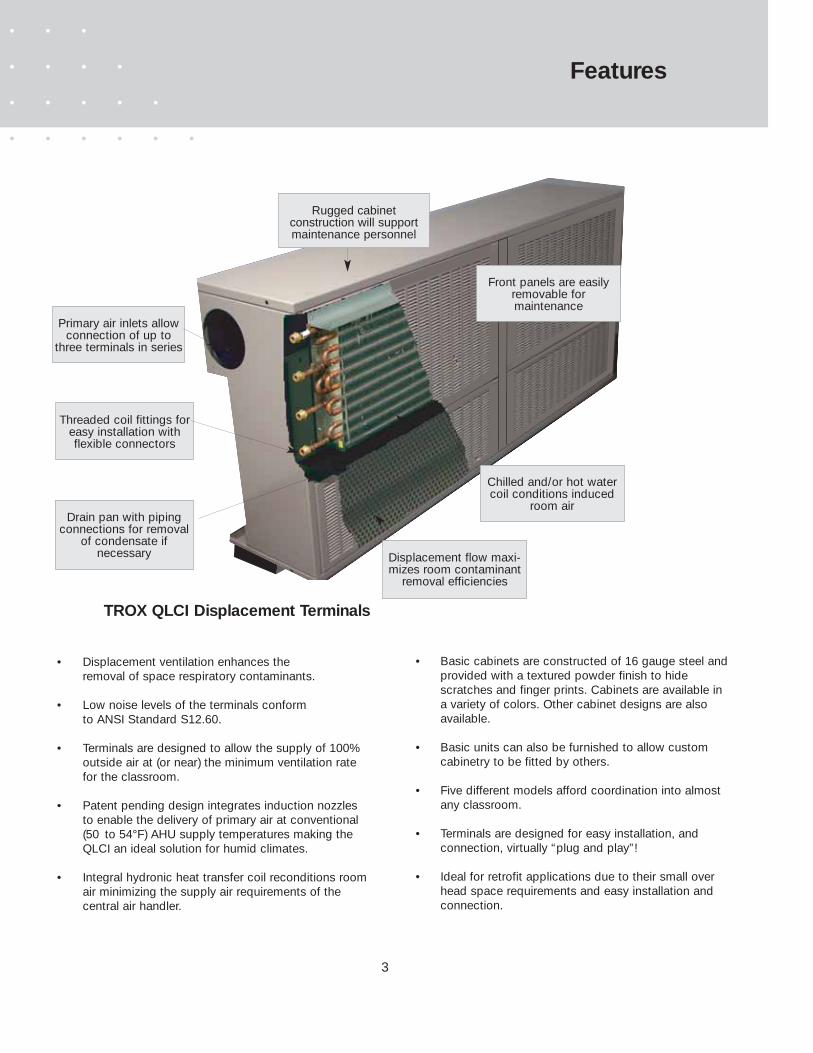
Features
Rugged cabinet construction will supportmaintenance personnel
Primary air inlets allowconnection of up to
three terminals in series
Threaded coil fittings foreasy installation withflexible connectors
Drain pan with piping connections for removal
of condensate if necessary
Front panels are easilyremovable for maintenance
Chilled and/or hot watercoil conditions induced
room air
Displacement flow maxi-mizes room contaminant
removal efficiencies
TROX QLCI Displacement Terminals
• Displacement ventilation enhances theremoval of space respiratory contaminants.
• Low noise levels of the terminals conform to ANSI Standard S12.60.
• Terminals are designed to allow the supply of 100% outside air at (or near) the minimum ventilation rate for the classroom.
• Patent pending design integrates induction nozzles to enable the delivery of primary air at conventional (50 to 54°F) AHU supply temperatures making the QLCI an ideal solution for humid climates.
• Integral hydronic heat transfer coil reconditions roomair minimizing the supply air requirements of the central air handler.
• Basic cabinets are constructed of 16 gauge steel andprovided with a textured powder finish to hide scratches and finger prints. Cabinets are available in a variety of colors. Other cabinet designs are also available.
• Basic units can also be furnished to allow custom cabinetry to be fitted by others.
• Five different models afford coordination into almost any classroom.
• Terminals are designed for easy installation, and connection, virtually “plug and play”!
• Ideal for retrofit applications due to their small overhead space requirements and easy installation and connection.

4
Displacement ventilation has been widely used throughoutEurope for over twenty-five years. This technology relieson natural convection to purge gaseous contaminantsfrom occupied levels of the space. Research documentsthe ventilation effectiveness of these systems as up totwice that of the mixed air systems used in today’sschools.
Figure 1 illustrates such a displacement conditioning system. Cool air is discharged through a supply outlet in alow sidewall (or floor) location. The face velocity is limited(to 50-60 FPM) in order to minimize the entrainment of(and mixing with) room air, thereby maintaining the thermalintegrity of the supply airflow. The discharge air falls to thefloor and spreads across the floor in a very thin layer. Itremains near the floor as it is restrained from rising bywarmer (ambient) air above it.
When convective heat sources such as people and equipment transfer heat to the medium surrounding them,natural convection currents form along their surfaces.
These currents rise due to natural buoyancy, entrainingambient air throughout their ascent. This rising air createsa thermal plume that rises above the heat source. Thisplume ascends to a level where it encounters either aphysical boundary or an equally warm pool of air, growingin volume as it rises. The volume of the plume and its dis-tance of travel are functions of the intensity of the heatsource.
As the plume rises, it draws air from the floor, conditionsthe occupant, and ventilates the respiratory level so thatthe occupants inhale the fresh air. Exhaled air is warmerthan ambient and thus rises with the thermal plume to anoverhead location where it can be exhausted. This singlevertical passage of fresh air through the breathing leveleliminates horizontal cross transmission of the respiratorypollutants (and associated contagious diseases) amongstthe occupants of the classroom.
Displacement Fundamentals
Figure 1 : Fundamentals of Displacement Ventilation
..............
5
The inherently low velocity discharge employed bydisplacement diffusers allows maintenance of low spacenoise levels while minimizing the effects of obstacles within the classroom on space air distribution.
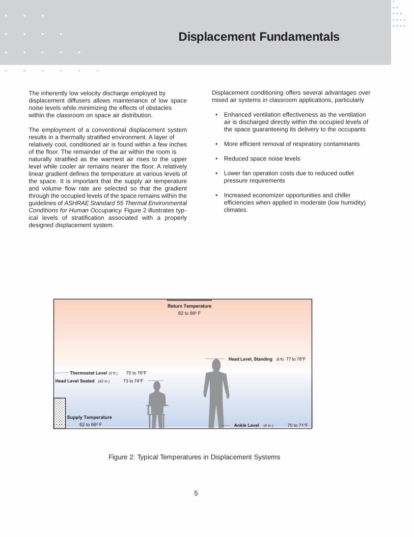
The employment of a conventional displacement systemresults in a thermally stratified environment. A layer of relatively cool, conditioned air is found within a few inchesof the floor. The remainder of the air within the room is naturally stratified as the warmest air rises to the upperlevel while cooler air remains nearer the floor. A relativelylinear gradient defines the temperature at various levels ofthe space. It is important that the supply air temperatureand volume flow rate are selected so that the gradientthrough the occupied levels of the space remains within theguidelines of ASHRAE Standard 55 Thermal EnvironmentalConditions for Human Occupancy. Figure 2 illustrates typ-ical levels of stratification associated with a properlydesigned displacement system.
Displacement conditioning offers several advantages overmixed air systems in classroom applications, particularly
• Enhanced ventilation effectiveness as the ventilation air is discharged directly within the occupied levels of the space guaranteeing its delivery to the occupants
• More efficient removal of respiratory contaminants
• Reduced space noise levels
• Lower fan operation costs due to reduced outlet pressure requirements
• Increased economizer opportunities and chillerefficiencies when applied in moderate (low humidity) climates.
Supply Temperature
62 to 66o F
Return Temperature
82 to 86o F
Ankle Level (4 in.) 70 to 71oF
Head Level, Standing (6 ft) 77 to 78oF
Head Level Seated (42 in.) 73 to 74oF
Thermostat Level (5 ft.) 75 to 76oF
Displacement Fundamentals
Figure 2: Typical Temperatures in Displacement Systems
6
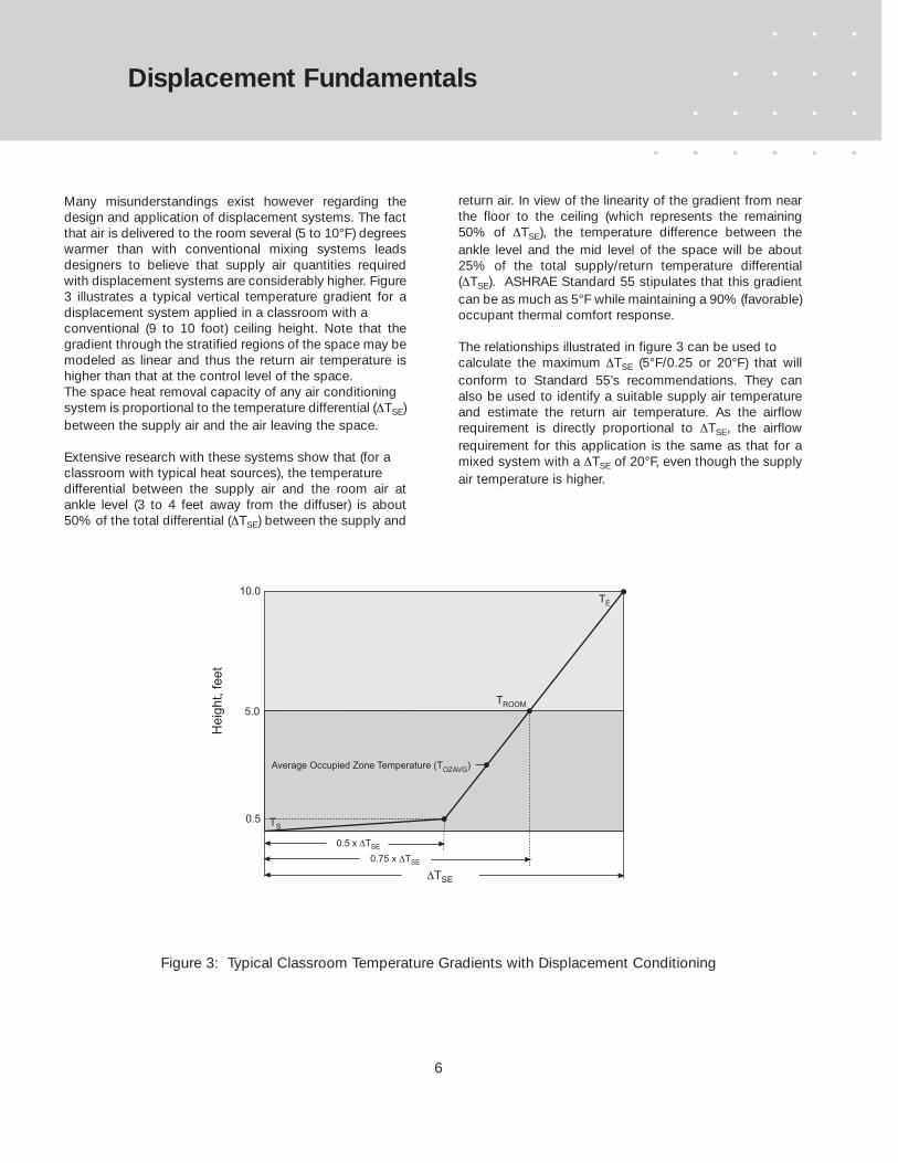
Many misunderstandings exist however regarding thedesign and application of displacement systems. The factthat air is delivered to the room several (5 to 10°F) degreeswarmer than with conventional mixing systems leadsdesigners to believe that supply air quantities requiredwith displacement systems are considerably higher. Figure3 illustrates a typical vertical temperature gradient for adisplacement system applied in a classroom with a conventional (9 to 10 foot) ceiling height. Note that thegradient through the stratified regions of the space may bemodeled as linear and thus the return air temperature ishigher than that at the control level of the space.The space heat removal capacity of any air conditioning system is proportional to the temperature differential (∆TSE)between the supply air and the air leaving the space.
Extensive research with these systems show that (for a classroom with typical heat sources), the temperature differential between the supply air and the room air atankle level (3 to 4 feet away from the diffuser) is about50% of the total differential (∆TSE) between the supply and
return air. In view of the linearity of the gradient from nearthe floor to the ceiling (which represents the remaining50% of ∆TSE), the temperature difference between theankle level and the mid level of the space will be about25% of the total supply/return temperature differential(∆TSE). ASHRAE Standard 55 stipulates that this gradientcan be as much as 5°F while maintaining a 90% (favorable)occupant thermal comfort response.
The relationships illustrated in figure 3 can be used to calculate the maximum ∆TSE (5°F/0.25 or 20°F) that willconform to Standard 55’s recommendations. They canalso be used to identify a suitable supply air temperatureand estimate the return air temperature. As the airflowrequirement is directly proportional to ∆TSE, the airflowrequirement for this application is the same as that for amixed system with a ∆TSE of 20°F, even though the supplyair temperature is higher.
∆TSE
0.5 x ∆TSE
0.75 x ∆TSE
He
igh
t, f
ee
t
5.0
0.5
TE
TS
TROOM
Average Occupied Zone Temperature (TOZAVG
)
10.0
Displacement Fundamentals
Figure 3: Typical Classroom Temperature Gradients with Displacement Conditioning
7
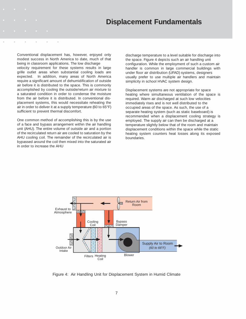
Conventional displacement has, however, enjoyed onlymodest success in North America to date, much of thatbeing in classroom applications. The low discharge velocity requirement for these systems results in largegrille outlet areas when substantial cooling loads areexpected. In addition, many areas of North Americarequire a significant amount of dehumidification of outsideair before it is distributed to the space. This is commonlyaccomplished by cooling the outside/return air mixture toa saturated condition in order to condense the moisturefrom the air before it is distributed. In conventional dis-placement systems, this would necessitate reheating theair in order to deliver it at a supply temperature (60 to 65°F)sufficient to prevent thermal discomfort.
One common method of accomplishing this is by the useof a face and bypass arrangement within the air handlingunit (AHU). The entire volume of outside air and a portionof the recirculated return air are cooled to saturation by theAHU cooling coil. The remainder of the recirculated air isbypassed around the coil then mixed into the saturated airin order to increase the AHU
discharge temperature to a level suitable for discharge intothe space. Figure 4 depicts such an air handling unit configuration. While the employment of such a custom air handler is common in large commercial buildings withunder floor air distribution (UFAD) systems, designers usually prefer to use multiple air handlers and maintainsimplicity in school HVAC system design.
Displacement systems are not appropriate for space heating where simultaneous ventilation of the space isrequired. Warm air discharged at such low velocities immediately rises and is not well distributed to the occupied areas of the space. As such, the use of a separate heating system (such as static baseboard) is recommended when a displacement cooling strategy isemployed. The supply air can then be discharged at a temperature slightly below that of the room and maintain displacement conditions within the space while the staticheating system counters heat losses along its exposedboundaries.
Supply Air to Room(60 to 66oF)Outdoor Air
Intake
CoolingCoil
HeatingCoil
Filters Blower
Exhaust toAtmosphere
Return Air fromRoom
BypassDamper
Displacement Fundamentals
Figure 4: Air Handling Unit for Displacement System in Humid Climate
8
Displacement with Induction
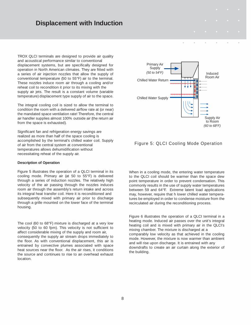
TROX QLCI terminals are designed to provide air qualityand acoustical performance similar to conventional displacement systems, but are specifically designed foroperation in North American climates. They are fitted witha series of air injection nozzles that allow the supply ofconventional temperature (50 to 55°F) air to the terminal.These nozzles induce room air through a cooling and/orreheat coil to recondition it prior to its mixing with the supply air jets. The result is a constant volume (variabletemperature) displacement type supply of air to the space.
The integral cooling coil is sized to allow the terminal tocondition the room with a delivered airflow rate at (or near)the mandated space ventilation rate! Therefore, the centralair handler supplies almost 100% outside air (the return airfrom the space is exhausted).
Significant fan and refrigeration energy savings are realized as more than half of the space cooling is accomplished by the terminal’s chilled water coil. Supplyof air from the central system at conventional temperatures allows dehumidification without necessitating reheat of the supply air.
Description of Operation
Figure 5 illustrates the operation of a QLCI terminal in itscooling mode. Primary air (at 50 to 55°F) is deliveredthrough a series of induction nozzles. The relatively highvelocity of the air passing through the nozzles inducesroom air through the assembly’s return intake and acrossits integral heat transfer coil. Here it is reconditioned and subsequently mixed with primary air prior to dischargethrough a grille mounted on the lower face of the terminalhousing.
The cool (60 to 68°F) mixture is discharged at a very lowvelocity (50 to 60 fpm). This velocity is not sufficient toaffect considerable mixing of the supply and room air, consequently the supply air stream drops immediately tothe floor. As with conventional displacement, this air isentrained by convective plumes associated with spaceheat sources near the floor. As the air rises, it conditionsthe source and continues to rise to an overhead exhaustlocation.
When in a cooling mode, the entering water temperatureto the QLCI coil should be warmer than the space dewpoint temperature in order to prevent condensation. Thiscommonly results in the use of supply water temperaturesbetween 59 and 64°F. Extreme latent load applicationsmay, however, require that h lower chilled water tempera-tures be employed in order to condense moisture from therecirculated air during the reconditioning process.
Figure 6 illustrates the operation of a QLCI terminal in aheating mode. Induced air passes over the unit’s integralheating coil and is mixed with primary air in the QLCI’smixing chamber. The mixture is discharged at a comparably low velocity as that achieved in the coolingmode. However, the mixture is now warmer than ambientand will rise upon discharge. It is entrained with any downdrafts to create an air curtain along the exterior ofthe building.
Figure 5: QLCI Cooling Mode Operation
Chilled Water Supply
Chilled Water Return
Primary AirSupply
InducedRoom Air
Supply Airto Room
(60 to 68oF)
(50 to 54oF)

9
Displacement with Induction
QLCI terminals are capable of assisting in maintaing mini-mal skin temperatures during night and weekend hourswhile the central air handling units remain off. In this mode,the integral reheat coil operates on a call for heat, drawingair from the floor. From this point, the buoyancy effect ofthe warm air causes it to rise and escape through the grilleon the upper face of the unit’s cabinet.
While maintaining delivery of the proper quantity of freshair is of utmost importance, it is should be assured that aportion of the air is distributed along the classroom floor atall times if the benefits of displacement ventilation are tobe maximized. The selection procedures that follow havebeen developed to assure that at least 40% of the total airflow is directed to the classroom in adisplacement manner,even when the space thermostat iscalling for heat.
• Improved Air Quality
Displacement ventilation improves the quality of the airin the classroom in several ways. First of all, its introduction within the occupied zone assures that allof the ventilation air is delivered to the occupants. Mixed systems that utilize ceiling diffusers approach aventilation effectiveness of 100% only when they are properly operating at their design airflow. This effectiveness can be as low as 40% when outlets aredelivering reduced (and/or warm) air quantities as thesupply air jet does not create entrainment sufficient tosustain mixing at lower levels of the space. The use ofdisplacement systems assures that the ventilation effectiveness exceeds 100% at all times. The verticalmigration of air in proximity to space heat sources assures that the warmest and most contaminated air is exhausted.
QLCI terminals deliver a constant volume of conditioned air to the space in the same manner as conventional displacement systems. Their unique design allows the conditioning and dehumidification ofoutside air (at or near the space minimum ventilation rate) for delivery as the primary air source. An equal amount of air must be exhausted, so there is no recirculation at the air handling unit. Contaminants and germs which have been removed are exhausted, preventing their spread to other classrooms served by thesame air handling unit.
Advantages of QLCI Terminals in a ClassroomEnvironment
QLCI displacement terminals are ideal for classroomapplications. Their employment assures a favorable learning environment by improving air quality while maintaining space noise levels far superior to other classroom HVAC systems. These systems also offer substantial operational cost savings over conventional airdelivery methods. This section describes some of theseadvantages in greater detail.Hot Water Supply
Hot Water Return
Primary AirSupply
InducedRoom Air
Supply Airto Room
(85 to 90oF)
(50 to 60oF)
Figure 6: QLCI Heating Mode Operation

10
Displacement with Induction
• Simplified Air Handling Unit Design
Unlike conventional displacement systems, supply airis delivered to the QLCI at 50 to 55°F then mixed withroom air to achieve its appropriate discharge temperature. This enables the employment of simple, inexpensive and readily available air handling equipment. Complicated bypass and economizer controls are eliminated, resulting in simple and reliable air handling plant operation.
• Reduced Maintenance Requirements
Space temperature control is accomplished by the thermostatic sequencing and modulation of a pair ofwater valves (one chilled and the other hot) feeding each classroom. There are no moving parts within theQLCI terminals themselves. This reliability in combination with the simple air handling unitconfiguration makes the system almost maintenancefree!
• Lower Space Acoustical Levels
The QLCI is designed to allow selection at space noise levels (NC 27) that are compliant with ANSI Standard S12.60. Where compliance is not required, the primary airflow rate (per terminal) can be increased while maintaining space low noise levels (up to NC 32). This still results in a far superior acoustical environment to that possible with unit ventilators and other equipment which employ integral fan assistance. In addition, the constant volume operation of these units assures that space acoustical levels remain uniform at all times.
• Smaller Equipment and Ductwork
Use of the integral coil in the QLCI for cooling recirculated room air significantly reduces space design (primary) air requirements. This also reduces the sizes and capacities of associated air handling and distribution equipment accordingly. Table 1 provides a comparison of such equipment capacity requirements (versus other popular classroom HVAC systems).
Table 1: Operational Comparison of Classroom HVAC Systems
LatentCooling
ClassroomVentilation
Design AHUAirflow
RefrigerationTonage
SpaceNC Level
SensibleCooling
UnitVentilators
VAV withReheat
FCU's andWSHP's
ConventionalDisplacement
QLCIDisplacement
Primary Air Primary andInduced Air
Primary andInduced Air
Primary Air Primary andInduced Air
Primary andInduced Air
Primary andInduced Air
Primary andInduced Air
Primary Air Primary Air
Primary Air Primary Air Primary Air Primary AirPrimary Air
N/A 1.3 CFM/sq.ft. 0,5 CFM/sq.ft. 1.6 CFM/sq.ft. 0.5 CFM/sq.ft.
190 Sq.Ft../Ton215 Sq.Ft../Ton 200 Sq.Ft../Ton 220 Sq.Ft../Ton 225 Sq.Ft../Ton
NC 40 to 45 NC 32 to 40 NC 38 to 45 NC 20 to 30 NC 25 to 32

11
Displacement with Induction
• Reduced Energy Costs
As in all displacement conditioning systems, air returned from the room is several degrees warmer than that at the occupied levels of the space. Since allof this air is exhausted (and not recirculated at the airhandler), a significant amount of space heat will be exhausted as well. In addition, the space airflow reduction and the use of chilled water to pre-cool recirculated room air result in significant operational energy reductions versus mixed systems. Figure 7 below compares the energy usage of the QLCI against several commonly used systems.
• Credits toward LEED© Certification
A number of LEED credits are may be achieved by the use of a displacement ventilation strategy as well as in the area of energy reduction.
ATLANTA BOSTON CHICAGO LOS ANGELES
VA
V w
ith R
ehea
t
VA
V w
ith R
ehea
t
VA
V w
ith R
ehea
t
VA
V w
ith R
ehea
t
Uni
t Ven
tilat
ors
Uni
t Ven
tilat
ors
Uni
t Ven
tilat
ors
Uni
t Ven
tilat
ors
QLC
I Dis
plac
emen
t
QLC
I Dis
plac
emen
t
QLC
I Dis
plac
emen
t
QLC
I Dis
plac
emen
t
Air Transport Costs
Cooling Costs
Heating Costs
$0.57
$0.68
$0.79
$0.59
$0.93
$0.83
$0.56
$0.70
$0.82$0.77
$0.95
$1.21
LOCATION
$0.20
$0.40
$0.60
$0.80
$1.00
$1.20
$1.40
$1.60
$1.80
$2.00
Ann
ual H
VAC
Ene
rgy
Cos
ts (U
S$
per F
T2 )
Figure 7: System Energy Comparisons for Various U.S. Cities

12
Application
CLASSROOM DESIGN GUIDELINES
The American Society of Heating, Refrigeration and AirConditioning Engineers (ASHRAE) establishes design requirements and guidelines for the conditioning and ventilating of classrooms. ASHRAE Standard 62Ventilation for Acceptable Indoor Air Quality stipulates thata minimum outside air delivery of 15 CFM per occupantshould be maintained at all times. ASHRAE Standard 55Thermal Environmental Conditions for Human Occupancyestablishes recommendations for design (dry and wetbulb) temperatures, velocities and allowable vertical space temperature gradients that will produce thermal comfortfor the space occupants. Standard 55-2004 recommends(in order to satisfy 90% of the occupants) that a) the class-room summer dry bulb temperature be maintainedbetween 73 and 79°F b) the space wet bulb temperatureshould not exceed 68°F, c) ambient velocities within theoccupied levels of the space should not exceed about 30FPM, and d) the temperature differential between the ankleand head level of the occupants should not exceed 5°F.Similarly, the Standard recommends that classroom winterdesign conditions be between 68 and 74°F dry bulb, withspace humidity levels bounded by a 36°F space dew pointand a 64°F wet bulb temperature.
ANSI Standard S12.60 Acoustical Performance Criteria,Design Requirements and Guidelines for Schools identifiesclassroom acoustical levels that are necessary to maintainan acceptable differential between the ambient noise andthe sound delivery level of an instructor (speaking withoutartificial amplification) necessary to produce easily under-standable reception to students within the classroom.
QLCI TERMINALS’ RANGE OF APPLICABILITY
TROX QLCI terminals are intended for classroom HVACapplications involving sensible heat gains up to 40 BTUHper square foot while maintaining noise levels conformingto ANSI Standard S12.60. This is achieved using a primaryair delivery that is 100% outside air equal to (or near) thespace minimum ventilation rate. The cooling mode selection procedures and examples within this catalog
apply a classroom design strategy that utilizes chilledwater temperatures above the space dew point (avoidingcondensation within the QLCI cooling coil) to condition thespace within the following parameters:
• Space sensible heat gains up to 40 BTUH/ft2.
• Primary air delivery of 100% outside air conditioned toa 50 to 54°F (saturation temperature) at an airflow rateequal to (or near) the mandated space ventilation rate.
• Classroom operational temperatures of 73 to 77°F dry bulb and humidity ratios between 70 and 78 grains (ofmoisture per pound of dry air). These conditions are well within the aforementioned recommendations of ASHRAE Standard 55-2004
• Classrooms with space sensible heat ratios (SHR) between 70 and 95% can be adequately dehumidifiedwithout necessity of condensation on the QLCI coils.
The range of application can be extended to include lower sensible heat ratios (higher latent loads) and/or lowerspace humidity ratios with the employment of an alternative design strategy using chilled water supply temperatures below the space dew point to produce condensation on the QLCI cooling coil.
Table 2 is intended to assist the designer in choosing theappropriate (standard or alternate) cooling design strategyto balance space sensible and latent cooling require-ments.This table can be used to identify combinations ofspace sensible cooling demand and humidity levels whichmay necessitate the employment of condensation withinthe QLCI terminals. Alternatively, space humidity ratiosmay be elevated and/or primary air humidity ratiosreduced to achieve desired results without condensation.

13
Application
Table 2: Primary Airflow Requirements for Treatment of Space Sensible and Latent Loads
1166 1177 1188 1199 2200 2211 2222 2233 2244 2255
85.0%
82.5%
80.0%
77.5% 1.09
75.0% 1.21 1.14 1.08
72.5% 1.33 1.26 1.19 1.12 1.07
70.0% 1.46 1.37 1.29 1.23 1.16 1.11 1.06
85.0%
82.5%
80.0%
77.5% 1.13 1.07
75.0% 1.27 1.20 1.13 1.07
72.5% 1.42 1.33 1.26 1.19 1.13 1.08
70.0% 1.56 1.47 1.38 1.31 1.25 1.19 1.13 1.08
85.0%
82.5% 1.13 1.07
80.0% 1.29 1.22 1.15 1.09
77.5% 1.46 1.37 1.29 1.23 1.16 1.11 1.06
75.0% 1.62 1.52 1.44 1.36 1.29 1.23 1.18 1.13 1.08
72.5% 1.78 1.67 1.58 1.50 1.42 1.36 1.29 1.24 1.19 1.14
70.0% 1.94 1.83 1.73 1.63 1.55 1.48 1.41 1.35 1.29 1.24
DDiiffffeerreennccee BBeettwweeeenn RRoooomm aanndd PPrriimmaarryy AAiirr HHuummiiddiittyy RRaattiioo (WROOM - WPRI),, GGrraaiinnssSSppaaccee SSeennssiibblleeHHeeaatt RRaattiioo (%)
AAiirrffllooww RRaattiioo (CFMLAT / CFMSENS)
UUssee ooff tthhee ttaabbllee aabboovvee::
SSppaaccee SSeennssiibblleeHHeeaatt GGaaiinn
(BTUH/ft2)
3300
3355
4400
Due to their high occupant density, classroom spaces typically experience significant latent loads which result in low space sensible heatratios (SHR). If adequate dehumidification is to be accomplished without the use of condensation on the QLCI coils, the space latent gainmust be satisfied by the introduction of sufficiently dry primary air. As the desired primary airflow to the QLCI terminals is considerablylower than that supplied to a conventional HVAC terminal, careful attention must be given to the selection of the humidity ratio andairflow rate of the primary air supply.
In certain cases, the primary airflow required to adequately dehumidify the space (without assistance from condensation on the QLCI coil)may exceed that which is necessary to provide sensible cooling of the space. The ratios (CFMLAT / CFMSENS) in the table indicate thepercentage primary airflow increase (over that required to satisfy the space sensible gain) that will be required to provide a specifieddifferential between the room humidty ratio (WROOM) and that of the primary air delivery (WPRI). This table is intended to assist thedesigner in identifying such cases and suggesting remedies where this occurs.
The shaded cells (with no value) indicate conditions where the space humidity ratio (WROOM) can be maintained by the delivery of primaryair at the humidity ratio differential indicated and at an airflow rate equal to that required to sensibly cool the space. Values in unshadedboxes represent the airflow ratio (CFMLAT / CFMSENS) that must be employed to affect the required differential (WROOM - WPRI) while notrequiring condensation on the QLCI cooling coil. Values in italics (shaded cells) represent combinations which can be achieved but perhapsnot practically as the airflow rate must be increased more than 25%. This may result in substantial energy penalties if 100% outdoorairflow is to be employed. Where such conditions exisit, it is recommended that the humidity ratio differential (WROOM - WPRI) be increasedor that the alternate design strategy (employing condensation on the QLCI coils) be considered.

14
SPACE HEAT GAINS IN STRATIFIED SYSTEMS
As is the case with all displacement conditioning systems,QLCI terminals are designed to create a thermally stratified environment that promotes the formation of heatplumes that convey convective heat gains (and their associated contaminant emissions) to the upper boundaries of the space where they can be exhausted.This rising heat plume induces ambient air in its proximityto fill the void it has created. In the case of plumes originating at or near the floor, the source of induced air isthe conditioned supply air layer. If the (convective) heatgain emanates from a higher level of the space, the air itinduces to fill the void is already stratified, the source isisolated and its heat emission does not reduce the reservoir of conditioned air at the floor.
Figure 8 illustrates design heat gains that are typical to a classroom with a perimeter exposure that is 50% glass. A gypsum board ceiling has been assumed, therefore anyheat gains from the roof (as well as the convective gainsfrom the light fixtures) will be removed by the exhaust airflow and have minimal affect on the classroom itself.
When determining the effective sensible heat gain (ESHG)of the space, all of the radiant gains (fenestration plus theradiant heat component from the lights, equipment andoccupants of the space) should be considered.
Convective heat gains that originate above the occupiedlevel (approximately 36 inches in the case of classrooms)
Application
Figure 8: Heat Gain Analysis for a Typical Classroom Served by QLCI System
SPACE DESIGN PARAMETERS
qW = 460 BTUH
qG = 922 BTUH
qF = 9000 BTUH
qOCC= 6750 * 0.75 = 5063 BTUH
qEQ = 4608 * 0.5 = 2304 BTUH
qLR = 2765 BTUH
qLC = 1843 BTUH
TR= 77°F
QP = 440 CFM
TP = 51°F
QI = 880 CFM
QS = 1320 CFM
TS = 61°F
QEXH = 440 CFM
TEXH = 85.0°F
QP = Primary airflow rate
TP = Primary air temperature
QI = Induced airflow rateQS = Supply airflow rateQEX= Exhaust airflow rate
TR = Room design temperature (5 ft. level)TEX = Exhaust air temperature
qOCC= SHG of occupantsqEQ = SHG of equipmentqLR = Radiant SHG of lightsqLC = Convective SHG of lightsqF = Radiant SHG of fenestrationqW = Convective SHG of wall
LEGEND
TSHG = 30 BTUH/FT2
No. Occupuants = 29Min. OA = 435 CFM Space WB = 64°FAverage occupied zone (DB) = 75°F Supply temperature = 51°F
Lighting = 4608 BTUH (1.5 W/FT2)
Equipment = 4608 BTUH (1.5 W/FT2)TA = Ankle level temperature
TA = 72°F
TOZAVG = 74.5°F
qG = Convective SHG of window
TOZAVG = Average occupied zone temperatureDimensions: 30'L x 30'W x 10'H
ESHG = 22.5 BTUH/FT2
qEXH = 1.1 x 440 x 34.0 = 16,445 BTUH
qCW = 1.1 x 880 x 9 = 8,712 BTUH
qEX = Heat removed by exhaust airqCW = Heat removed by chilled water
qOCC= 6750 * 0.25 = 1687 BTUH
qEQ = 4608 * 0.5 = 2304 BTUH
15
Application
escape naturally without requiring (conditioned) supply airto feed their convection plumes. They need not be considered in space supply air calculations. In addition,some portion of the convective gain from occupants andequipment located near the top of the occupied zoneescapes naturally, so these gains can be factored according to the percentage of their total sensible gainthat affects conditions in the occupied zone.
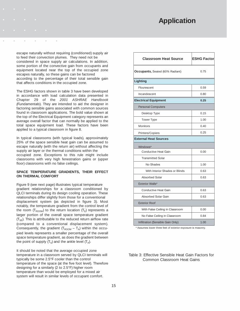
The ESHG factors shown in table 3 have been developedin accordance with load calculation data presented inChapter 29 of the 2001 ASHRAE Handbook(Fundamentals). They are intended to aid the designer infactoring sensible gains associated with common sourcesfound in classroom applications. The bold value shown atthe top of the Electrical Equipment category represents anaverage overall factor that can normally be applied to thetotal space equipment load. These factors have beenapplied to a typical classroom in figure 8.
In typical classrooms (with typical loads), approximately25% of the space sensible heat gain can be assumed toescape naturally (with the return air) without affecting thesupply air layer or the thermal conditions within the occupied zone. Exceptions to this rule might includeclassrooms with very high fenestration gains or (upperfloor) classrooms with no false ceilings.
SPACE TEMPERATURE GRADIENTS, THEIR EFFECTON THERMAL COMFORT
Figure 9 (see next page) illustrates typical temperature gradient relationships for a classroom conditioned byQLCI terminals during its design cooling operation. These relationships differ slightly from those for a conventional displacement system (as depicted in figure 3). Mostnotably, the temperature gradient from the control level ofthe room (TROOM) to the return location (TE) represents alarger portion of the overall space temperature gradient(TSE). This is attributable to the reduced return airflow rate(compared to a conventional displacement system).Consequently, the gradient (TROOM – TA) within the occu-pied levels represents a smaller percentage of the overallspace temperature gradient, as does the gradient betweenthe point of supply (TS) and the ankle level (TA).
It should be noted that the average occupied zone temperature in a classroom served by QLCI terminals willtypically be some 2.5°F cooler than the control temperature of the space (at the five foot level). Thereforedesigning for a similarly (2 to 2.5°F) higher room temperature than would be employed for a mixed air system will result in similar levels of occupant comfort.
Lighting
Flourescent 0.59
Incandescent 0.80
Electrical Equipment 0.25
Desktop Type 0.15
Tower Type 1.00
Monitors 0.40
Printers/Copiers 0.25
External Heat Sources
Conductive Heat Gain 0.00
Transmitted Solar
No Shades 1.00
With Interior Shades or Blinds 0.63
Absorbed Solar 0.63
Conductive Heat Gain 0.63
Absorbed Solar Gain 0.63
With False Ceiling in Classroom 0.00
No False Ceiling in Classroom 0.84
Infiltration (Sensible Gain Only) 1.00
* Assumes lower three feet of exterior exposure is masonry.
Windows*
Exterior Walls*
Exterior Roof
Personal Computers
ESHG FactorClassroom Heat Source
Occupants, Seated (60% Radiant) 0.75
Table 3: Effective Sensible Heat Gain Factors forCommon Classroom Heat Gains

16
Figure 9 is accompanied by an example illustrating its gradient relationships’ use in determining various spacetemperatures. The example illustrates a room designed fora 77°F control temperature at the five (5) foot elevation. Ifthe temperature gradient between the ankle (TA) and thecontrol (TROOM) levels of the space is not to exceed 5°F(per ASHRAE Standard 55 recommendations), the discharge temperature of the air entering the room shouldnot be below 61°F. Assuming that the supply airflow rate(at this supply temperature) matches the design spacecooling load, the return air temperature is estimated to be86°F. The average occupied zone temperature is 74.5°F.
Table 4 below recommends maximum room to supply airtemperature differential for maintaining specified occupiedair gradients.
Certain practices should be observed when designing andselecting QLCI terminals for cooling applications in orderto achieve a high degree of thermal comfort.
• The supply air temperature (TS) should be at least 60°F.
• Stationary occupants should not be located within three feet of the QLCI terminals.
• The induced air inlet (top panel of the terminal) shouldnot be restricted by the placement of furniture, etc. directly against it.
• Return air inlets should be placed as high as possible,and at least six feet above the floor.
∆TSE
0.45 x ∆TSE
0.65 x ∆TSE
Heig
ht, feet
5.0
0.5
TE
TS
TROOM
Average Occupied Zone Temperature (TOZAVG
)
CLASSROOM EXAMPLE
TA
TROOM = 77 oF
TROOM - TA = 5 oF
TROOM - TS = 0.65 x ∆TSE
= 0.65 x 25= 16 oF
= 5 / 0.20
∆TSE = (TROOM - TA) / 0.20
= 25 oF
TS = TROOM - 16 oF
= 61 oF
TE = TS + ∆TSE
= 86 oF
10.0
Application
13.0 13.5 14.0 14.5 15.0 15.5 16.0
4.0 4.2 4.3 4.5 4.6 4.8 4.9
20.0 20.8 21.5 22.3 23.1 23.8 24.6
T ROOM - T SUPPLY (°F)
T OZ (°F)
T SE (°F)
Figure 9: Typical Classroom Temperature Gradients Using displacement with Induction
Table 4: Space Temperature Gradient Relationships with QLCI Systems
17
• Calculation of the supply airflow rate required for provision of adequate space ventilation
ASHRAE Standard 62 stipulates a minimum of 15 CFM perperson of outside air should be maintained at all times.The primary and supply airflow rates required to accom-plish this are:
QPRI = #Occupants x 15 CFM/ea.and,
QSUPPLY = 3 x QPRI
• Calculation of the supply airflow rate required to maintain the desired space humidity level
Without the assistance by condensation on the QLCI cooling coil, the task of maintaining adequate spacehumidity levels is borne entirely by the primary airflowdelivered to the QLCI terminals. The humidity (WSUPPLY)ratio (grains moisture per pound dry air) of the supply air isa determined by the humidity ratio of the primary air (WPRI)and that of the room air (WROOM) induced through the QLCIcoil and is calculated as:
WSUPPLY = (0.33 x WPRI) + (0.67 x WROOM)
The supply airflow (QSUPPLY) required to adequately dehumidify the space is a function of the space latent heatgain (LHG) and the humidity ratio of the supply air, and canbe calculated as:
QSUPPLY = LHG / [0.68 x (WROOM - WSUPPLY )]
It is advantageous to limit the primary air supply (QPRI) tothe QLCI terminals to a flow rate at or near the space minimum ventilation rate, whenever possible. Doing sominimizes system energy costs and space acoustical levels. When this primary airflow is solely responsible formaintaining space humidity levels, it may be necessarythat the primary air be conditioned to a dew point temperature of 45 to 50°F to offset the low primary airflowrate. Additional discussion of latent gains is presented intable 2 (page 13).
The design airflow rate is the maximum required to offsetthe sensible and latent space heat gains and to provideminimum ventilation of the space. Example 1 illustratesthe calculation procedure.
SPACE AIRFLOW CALCULATIONS
The supply airflow must be sufficient to offset the sensibleheat gain that affects the occupied levels of the space aswell as provide adequate classroom ventilation. If the preferred non-condensing design strategy is to beemployed, the supply airflow must also provide adequatespace dehumidification. In this case, both the ventilationand dehumidification processes are accomplished by theprimary air ducted to the QLCI terminals.
QLCI terminals maintain a constant volume delivery (QSUPPLY) of conditioned air to the space. The temperatureof the supply airflow is varied (by means of the chilledwater flow rate through the QLCI coils) in response to aspace temperature sensor. The primary air supply (QPRI) tothe QLCI terminals is also constant volume and is 1/3 thesupply airflow to the room.
The determination of the required supply (and primary) airquantity therefore involves calculation for each of the threeaforementioned processes. The subsections below andthe example that follows detail the procedures for determining the classroom airflow requirements.
• Calculation of the supply airflow required to offset sensible heat gains affecting the space occupants
Pages 13 and 14 discuss sensible heat gains in stratifiedair systems and introduce procedures for factoring thosegains. The factors in table 3 can be applied to the sensible heat contribution of each heat source within theclassroom to estimate its effect on the thermal comfort ofthe occupants. This effect is referred to as the effectivesensible heat gain (ESHG) relating to the source. TheESHG’s for all of the sources are then summed to obtainthe classroom ESHG that must be offset by the supply airflow. The supply airflow rate (QSUPPLY) required to offsetthe effective sensible gain is:
QSUPPLY = Space ESHG / (1.1 x TROOM – TSUPPLY)
An acceptable value for TROOM - TSUPPLY can be determinedby using the gradient relationships in figure 9 or by referring to table 4.
Application
18
Example 1
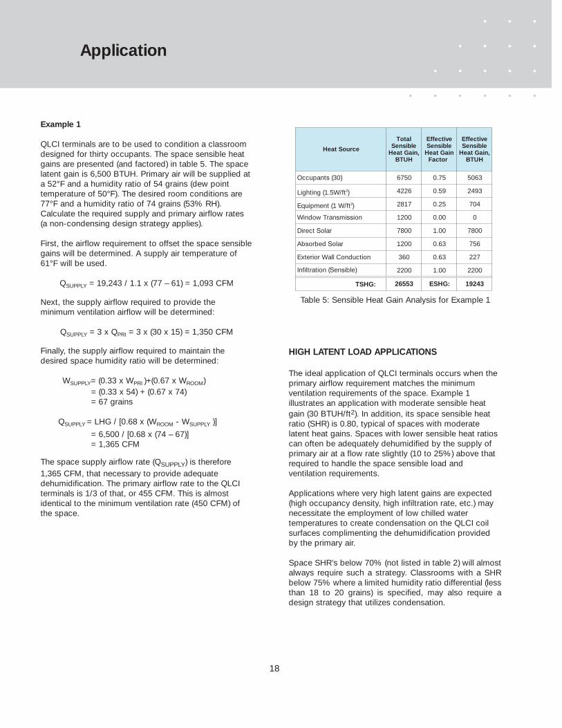
QLCI terminals are to be used to condition a classroomdesigned for thirty occupants. The space sensible heatgains are presented (and factored) in table 5. The spacelatent gain is 6,500 BTUH. Primary air will be supplied ata 52°F and a humidity ratio of 54 grains (dew point temperature of 50°F). The desired room conditions are77°F and a humidity ratio of 74 grains (53% RH).Calculate the required supply and primary airflow rates(a non-condensing design strategy applies).
First, the airflow requirement to offset the space sensiblegains will be determined. A supply air temperature of61°F will be used.
QSUPPLY = 19,243 / 1.1 x (77 – 61) = 1,093 CFM
Next, the supply airflow required to provide the minimum ventilation airflow will be determined:
QSUPPLY = 3 x QPRI = 3 x (30 x 15) = 1,350 CFM
Finally, the supply airflow required to maintain thedesired space humidity ratio will be determined:
WSUPPLY= (0.33 x WPRI )+(0.67 x WROOM)= (0.33 x 54) + (0.67 x 74)= 67 grains
QSUPPLY = LHG / [0.68 x (WROOM - WSUPPLY )]
= 6,500 / [0.68 x (74 – 67)]= 1,365 CFM
The space supply airflow rate (QSUPPLY) is therefore1,365 CFM, that necessary to provide adequate dehumidification. The primary airflow rate to the QLCIterminals is 1/3 of that, or 455 CFM. This is almost identical to the minimum ventilation rate (450 CFM) ofthe space.
HIGH LATENT LOAD APPLICATIONS
The ideal application of QLCI terminals occurs when theprimary airflow requirement matches the minimum ventilation requirements of the space. Example 1illustrates an application with moderate sensible heatgain (30 BTUH/ft2). In addition, its space sensible heatratio (SHR) is 0.80, typical of spaces with moderatelatent heat gains. Spaces with lower sensible heat ratioscan often be adequately dehumidified by the supply ofprimary air at a flow rate slightly (10 to 25%) above thatrequired to handle the space sensible load and ventilation requirements.
Applications where very high latent gains are expected(high occupancy density, high infiltration rate, etc.) maynecessitate the employment of low chilled water temperatures to create condensation on the QLCI coilsurfaces complimenting the dehumidification providedby the primary air.
Space SHR’s below 70% (not listed in table 2) will almostalways require such a strategy. Classrooms with a SHRbelow 75% where a limited humidity ratio differential (lessthan 18 to 20 grains) is specified, may also require adesign strategy that utilizes condensation.
Application
6750 0.75 5063
4226 0.59 2493
2817 0.25 704
1200 0.00 0
7800 1.00 7800
1200 0.63 756
360 0.63 227
2200 1.00 2200
26553 ESHG: 19243
Heat Source
TotalSensible
Heat Gain, BTUH
EffectiveSensible
Heat Gain Factor
EffectiveSensible
Heat Gain, BTUH
Occupants (30)
Lighting (1.5W/ft2)
Equipment (1 W/ft2)
Window Transmission
TSHG:
Direct Solar
Absorbed Solar
Exterior Wall Conduction
Infiltration (Sensible)
Table 5: Sensible Heat Gain Analysis for Example 1
19
Application
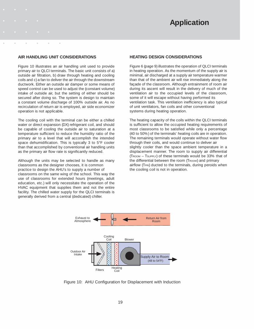
AIR HANDLING UNIT CONSIDERATIONS
Figure 10 illustrates an air handling unit used to provideprimary air to QLCI terminals. The basic unit consists of a)outside air filtration, b) draw through heating and coolingcoils and c) a fan to deliver the air through the downstreamductwork. Either an outside air damper or some means ofspeed control can be used to adjust the (constant volume)intake of outside air, but the setting of either should besecured after doing so. The system is design to maintaina constant volume discharge of 100% outside air. As norecirculation of return air is employed, air side economizeroperation is not applicable.
The cooling coil with the terminal can be either a chilledwater or direct expansion (DX) refrigerant coil, and shouldbe capable of cooling the outside air to saturation at atemperature sufficient to reduce the humidity ratio of theprimary air to a level that will accomplish the intendedspace dehumidification. This is typically 3 to 5°F coolerthan that accomplished by conventional air handling unitsas the primary air flow rate is significantly reduced.
Although the units may be selected to handle as manyclassrooms as the designer chooses, it is common practice to design the AHU’s to supply a number of classrooms on the same wing of the school. This way theuse of classrooms for extended hours (meetings, adulteducation, etc.) will only necessitate the operation of theHVAC equipment that supplies them and not the entirefacility. The chilled water supply for the QLCI terminals isgenerally derived from a central (dedicated) chiller.
HEATING DESIGN CONSIDERATIONS
Figure 6 (page 9) illustrates the operation of QLCI terminalsin heating operation. As the momentum of the supply air isminimal, air discharged at a supply air temperature warmerthan that of the ambient air will rise immediately along thefaçade of the classroom. Although entrainment of room airduring its ascent will result in the delivery of much of theventilation air to the occupied levels of the classroom,some of it will escape without having performed its ventilation task. This ventilation inefficiency is also typicalof unit ventilators, fan coils and other conventional systems during heating operation.
The heating capacity of the coils within the QLCI terminalsis sufficient to allow the occupied heating requirements ofmost classrooms to be satisfied while only a percentage(40 to 50%) of the terminals’ heating coils are in operation.The remaining terminals would operate without water flowthrough their coils, and would continue to deliver air slightly cooler than the space ambient temperature in adisplacement manner. The room to supply air differential(TROOM – TSUPPLY) of these terminals would be 33% that ofthe differential between the room (TROOM) and primary airflow (TPRI) ducted to the terminals, during peroids whenthe cooling coil is not in operation.
Supply Air to Room(48 to 54oF)
Outdoor AirIntake
CoolingCoil
HeatingCoilFilters
Blower
Exhaust toAtmosphere
Return Air fromRoom
Figure 10: AHU Configuration for Displacement with Induction

20
Application
Figure 11 illustrates the occupied heating operationof four terminals selected to condition a classroomspace. The two innermost terminals (QLCI-RT andQLCI-LT) supply warm air according to the spacedemand while the other two terminals continue tosupply air in a displacement manner.
NIGHT SETBACK HEATING OPERATION
The heating coils in the QLCI terminals can also beused to provide a limited degree of static heat to thespace while the air handling unit is not operating.This static heating capacity is detailed in table 7(page 31). If the space setback heating requirementexceeds that of the QLCI terminals configured forunoccupied heating, the operational strategy illustrated in figure 12 may sufficiently enhance thestatic heating capacity. It involves equipment roompiping which enables coils in all of the QLCI terminals to be used for unoccupied heating. If thisstrategy cannot be implemented or is not sufficient,the air handling units can be energized upon a dropin space temperature below the set back value toenhance the heating capacity of the QLCI terminals.
All QLCI's fed through CHW piping circuit
QLCI's configured with (4 Pipe) Heating Coil
HOT WATER PUMP(Off)
CHILLED WATER PUMP(On)
CentralChiller
Boiler
3 way diverting valve
3 way diverting valve
3 way diverting valve
Setback signal to classroom thermostats
AHUFans
Fans Off
Figure 12: Enhanced Setback Heating
QQLLCCII -- RRTTHeat and Cool
QQLLCCII -- LLTTHeat and Cool
QQLLCCII -- RREECooling Only
QQLLCCII -- LLEECooling Only
QQLLCCII -- RRTTHeat and Cool
QQLLCCII -- LLTTHeat and Cool
QQLLCCII -- RREECooling Only
QQLLCCII -- LLEECooling Only
TTeerrmmiinnaall OOppeerraattiioonn DDuurriinngg OOccccuuppiieedd HHeeaattiinngg MMooddee
TTeerrmmiinnaall OOppeerraattiioonn DDuurriinngg CCoooolliinngg MMooddee
Figure 11: QLCI Terminal Operation( 4 Pipe Configuration )

21
Application
CONDENSATION ISSUES AND PREVENTION
Whether used in a standard (non-condensing) or alternate (condensing) cooling design operation, all QLCIterminals are furnished with condensate trays which willcollect any condensation which may occur on the cooling coil surface. It is common that classrooms haveoperable windows whose opening may result in spacedew point levels higher than the QLCI chilled water supply temperature. In addition, corridor doors may beleft open for extended periods resulting in an elevation ofthe dew point temperature within the classroom wing.When either of these conditions occur, condensation willstart to form. It is recommended that these collectiontrays be piped such that the condensate is removed.
Condensation from a brief period of elevated space dewpoints can usually be evaporated within the tray while theterminals continue to operate in a cooling mode, but thecost of piping the condensate tray is low and doing soassures efficient removal of the condensate. In any casecondensate trays should be cleaned from time to time andare easily accessed through the induction panels of theQLCI terminals.
In the event condensation is to be avoided entirely, thereare numerous control strategies to assure this. Figure 13below illustrates one such condensation prevention strategy. It should be noted, however, that employment ofthese strategies may significantly increase the cost andcomplexity of the building control system. For more detailson condensation prevention, contact TROX USA.
Figure 13: Condensation Prevention with QLCI Terminals
Space Thermostat
3-Way Valve
Regulator Valve
CHILLED WATER SUPPLY
CHILLED WATER RETURN
To QLCI Units
SurfaceCondesation
Sensor
If the surface sensor detects condensation on the supply
water pipe, the 3- way valve is positioned to bypass chilled
water to return. This continues until moisture has evaporated
upon which chilled water control is returned to the
space thermostat.

22
Application
BASIC PIPING AND DUCTWORK
Figure 13 illustrates the basic classroom piping and ductwork required for the QLCI system. Primary air isdelivered to the QLCI terminals through 6” round ductslocated in each corner of the room along its exterior exposure. Four pipes (two in the case of a 2 pipe configuration) are also delivered to QLCI feed locations.
The QLCI terminals are commonly connected in series,with a maximum of three terminals fed by a single ductdrop. The water flow to each classroom is controlled by asingle chilled and/or hot water valve located in the supplywater pipes where they enter the space. The primary airflow to the room may also be reduced during unoccupied periods by providing a two position constantvolume regulator (type RNE) positioned by a signal froman occupancy sensor.
If building codes stipulate the use of demand control ventilation, a CO2 sensor in the return air plenum can beused to reset the primary air supply volume by means of acontrol damper in the duct supplying the classroom.
In cases where the alternate (condensing) design strategy
is employed it may also be necessary to provide a reheatcoil to maintain an acceptable supply air temperature tothe space. The use of low temperature chilled water coolsthe induced room air to a dew point temperature thatallows it to compliment the dehumidification of the primaryair. Such cooling may reduce the temperature of the airmixture leaving the QLCI terminal to a level beyond thatwhich would be recommended for providing thermal comfort. To avoid this, the primary air may be reheatedbefore it enters the QLCI terminal. The amount of reheatprovided is determined by the space thermostat and usedto control the temperature of the space. This is further discussed in the cooling design procedures (page 40 and41) and its necessity illustrated in Design and SelectionExample 3 (page 44).
Figure 14: Typical Classroom Piping and Ductwork Configuration
Chilled WaterSupply
Hot WaterSupply
Primary AirSupply
Reheat Coil(where applicable)
QLCI - LE QLCI - RT QLCI - LT QLCI - RE
Space Thermostat
AirflowRegulator

23
Application
INSTALLATION OF QLCI TERMINALS
QLCI terminals are designed to afford easy installation andaccess for maintenance. Figure 15 below details theinstallation of two QLCI terminals, mounted in series. Theleft hand unit is a model QLCI-LE while the adjacent terminal is a model QLCI-RT. A mirror image would likelybe installed from the right hand side of the exterior exposure of the classroom (using QLCI-RE and QLCI-LT models).
Most classrooms will require QLCI terminals be installedalong 75 to 80% of their external exposure to provide ade-quate space conditioning and ventilation at noise levelscompliant with ANSI S12.60.
An architectural duct cover is available which covers thesupply air duct as well as the vertical pipe runs. This coveris detailed as an option in the ordering procedures whichare presented on page 47. Piping and ductwork can alsobe housed in the classroom wall. In such cases, QLCI-CS terminals may be used for the initial service connection inlieu of the top entry (-LE and -RE) models.
Step 1:
Secure two 2 x 4 studs as shown along the perimeterwall. The studs should run the length of the QLCIinstallation less 4" adjacent to the wall where thepipe feeds are located. The water pipes should beran between the studs and secured to the wall.Threaded (1/2" male NPT) connectors must beprovided on each pipe 2 to 3" from the point wherethe QLCI terminals connect to each other.
Step 2:
Remove the face panels from the QLCI terminals,then position the first terminal against the wall. Drivelag bolts through its (4) mounting brackets to secureit to the mounting studs. Connect the terminal to thewater piping using braided stainless steel tubing(1/2" female NPT on each end). Connect the entryspigot on the QLCI terminal to a 6" diameter supplyair duct.
Step 3:
Position the remaining QLCI terminal(s) against thewall and drive lag bolts through the (4) mountingbrackets to secure them to the mounting studs.Connect the terminal(s) to the water piping usingbraided stainless steel tubing (1/2" female NPT oneach end). Slide the connector sleeve from theadjacent terminal onto the entry spigot and seal theconnection. Replace the face panels of the terminals.
5 3/4"
13"
Figure 15: Installation of QLCI Terminals in a Classroom
24
Dimensional Information
QLCI-LT QLCI-LE
3 1/8"
20 5/8"
Cabinet Left End Panel
QLCI-RE QLCI-RE
20 5/8"
3 1/8"
Cabinet Right End Panel
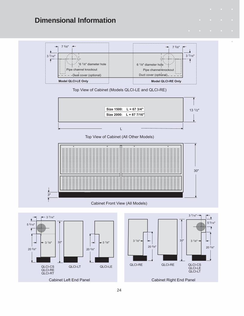
Cabinet Front View (All Models)
3 7/16"
7 5/8"
6 1/8" diameter hole 6 1/8" diameter hole
Duct cover (optional) Duct cover (optional)
Pipe channel knockoutPipe channel knockout
7 5/8"
3 7/16"
Model QLCI-LE Only Model QLCI-RE Only
13 1/2" Size 1500: L = 67 3/4"
Top View of Cabinet (All Other Models)
Top View of Cabinet (Models QLCI-LE and QLCI-RE)
30"
L
Size 2000: L = 87 7/16"
3"
QLCI-CSQLCI-LEQLCI-LT
20 5/8"
5 5/16"
3 7/16"
QLCI-CSQLCI-REQLCI-RT
20 5/8"
30"30"
3 1/8"
5 5/16"
3 7/16"
3 1/8"

25
Dimensional Information
Left (top) duct entry
Left (side) duct entry
Right (side) duct entry
Right (top) duct entry
3TL
3SL
3 Units in Series
3TR
3SR
2TL
2SL
2TR
2SR
2 Units in Series Use QLCI-CS where shaded
QLCI-CS WITH CABINET
QLCI-CS WITHOUT CABINET
25 3/4"
Optional 2"MERV-8
Filter
4 1/8"
4 1/8"
3 1/8"
4 7/8"
11/2"
1/2" NPTThreads
L - 9 3/8"2 3/8"
4 1/8"
2 3/8"
4 1/8"
5 7/8" dia. inlet
2 3/4"L - 10 1/2"
15 3/4"
5 7/8" dia. inlet
8 5/8"
14 5/8"
3 15/16"1 15/16"
Telescoping connection duct
(QLCI / 1500 Only)
7 1/2"
2 7/8"

26
Dimensional Information
QLCI - LE WITH CABINET
QLCI - LE WITHOUT CABINET
Left (top) duct entry
Left (side) duct entry
Right (side) duct entry
Right (top) duct entry
3TL
3SL
3 Units in Series
3TR
3SR
2TL
2SL
2TR
2SR
2 Units in Series Use QLCI-LE where shaded
1/2" NPTThreads
3 15/16"2 3/8"
4 1/8"
5 7/8" dia. inlet
2 3/4"
15 3/4"3 1/8"
4 7/8"
Optional 2"MERV-8
Filter25 3/4"
11/2"
8 3/16"
4 1/8"
7 1/2"
2 7/8"
8 5/8"
14 5/8"
L - 10 1/2"
(QLCI / 1500 Only)
L - 9 3/8"
3 1/2"
3 15/16"
1 15/16"
Duct cover (optional)
27
Dimensional Information
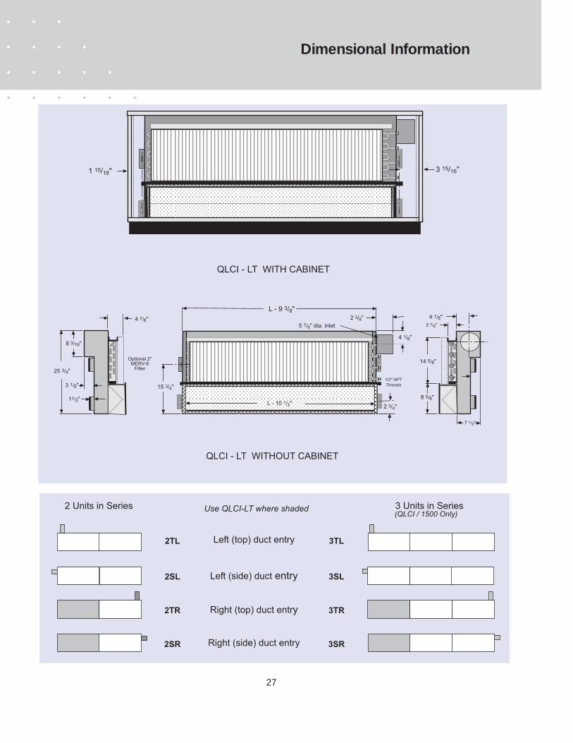
QLCI - LT WITHOUT CABINET
Left (top) duct entry
Left (side) duct entry
Right (side) duct entry
Right (top) duct entry
3TL
3SL
3 Units in Series
3TR
3SR
2TL
2SL
2TR
2SR
2 Units in Series Use QLCI-LT where shaded
QLCI - LT WITH CABINET
1 15/16" 3 15/16"
1/2" NPTThreads
2 3/8"
4 1/8"
5 7/8" dia. inlet
2 3/4"
15 3/4"
7 1/2"
2 7/8"
8 5/8"
14 5/8"
3 1/8"
4 7/8"
Optional 2"MERV-8
Filter25 3/4"
11/2"
8 3/16"
4 1/8"
L - 10 1/2"
L - 9 3/8"
(QLCI / 1500 Only)

28
QLCI - RE WITHOUT CABINET
Left (top) duct entry
Left (side) duct entry
Right (side) duct entry
Right (top) duct entry
3TL
3SL
3 Units in Series
3TR
3SR
2TL
2SL
2TR
2SR
2 Units in Series Use QLCI-RE where shaded
3 15/16" 1 15/16"
Telescoping connection duct
QLCI - RE WITH CABINET
Duct cover (optional)
1/2" NPTThreads
2 3/8"
4 1/8"
5 7/8" dia. inlet
2 3/4"
15 3/4"
3 15/16"
25 3/4"
Optional 2"MERV-8
Filter
4 1/8"
3 3/8"
3 1/8"
4 7/8"
11/2"
7 1/2"
2 7/8"
8 5/8"
14 5/8"
3 3/8"L - 9 3/8"
L - 10 1/2"
(QLCI / 1500 Only)
8 3/16"
Dimensional Information

29
QLCI - RT WITH CABINET
QLCI - RT WITHOUT CABINET
Left (top) duct entry
Left (side) duct entry
Right (side) duct entry
Right (top) duct entry
3TL
3SL
3 Units in Series
3TR
3SR
2TL
2SL
2TR
2SR
2 Units in Series Use QLCI-RT where shaded
3 15/16"1 15/16"
Telescoping connection duct
1/2" NPTThreads
2 3/8"
4 1/8"
5 7/8" dia. inlet
2 3/4"
15 3/4"
25 3/4"
Optional 2"MERV-8
Filter
4 1/8"
4 1/8"
3 1/8"
4 7/8"
11/2"L - 10 1/2"
L - 9 3/8"
(QLCI / 1500 Only)
7 1/2"
2 7/8"
8 5/8"
14 5/8"
8 3/16"
Dimensional Information
30
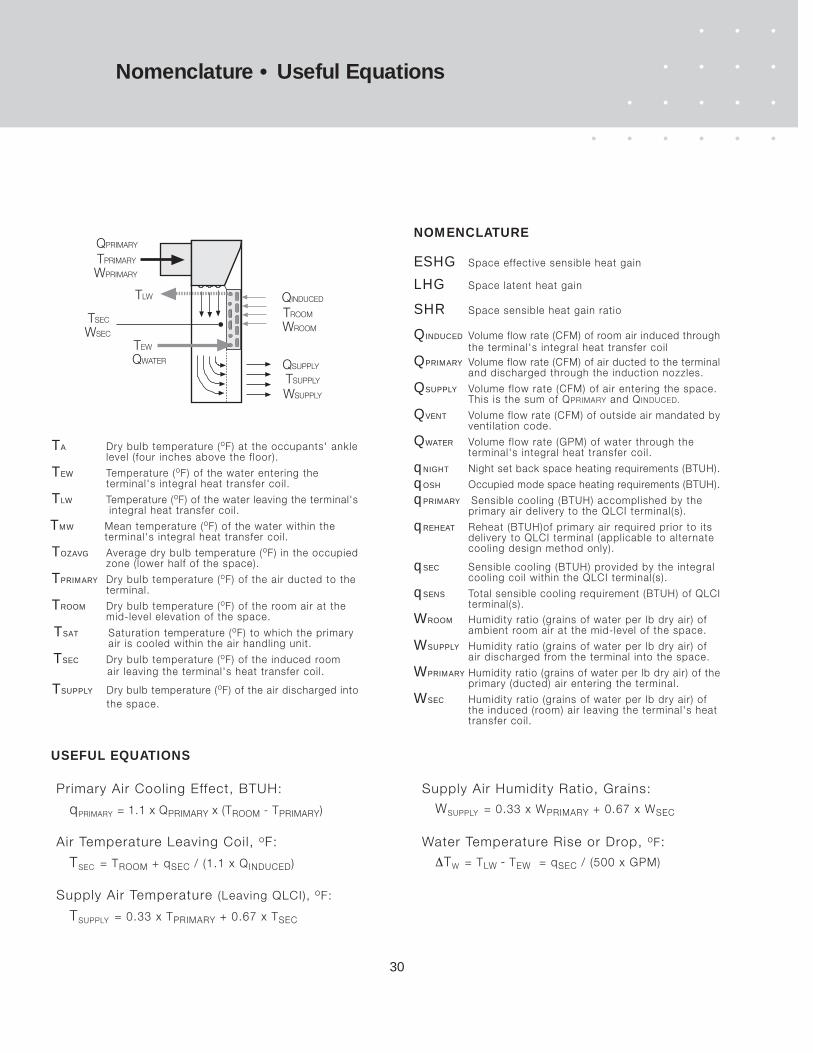
Nomenclature • Useful Equations
QPRIMARY
TPRIMARY
TEW
TLW
QSUPPLY
TSUPPLY
QINDUCED
TROOM
WROOM
WSUPPLY
WPRIMARY
TSEC
WSEC
QWATER
WSUPPLY Humidity ratio (grains of water per lb dry air) of air discharged from the terminal into the space.
WPRIMARY Humidity ratio (grains of water per lb dry air) of the primary (ducted) air entering the terminal.
WSEC Humidity ratio (grains of water per lb dry air) of the induced (room) air leaving the terminal's heat transfer coi l.
WROOM Humidity ratio (grains of water per lb dry air) of ambient room air at the mid-level of the space.
NOMENCLATURE
QSUPPLY Volume f low rate (CFM) of air entering the space. This is the sum of QPRIMARY and QINDUCED.
QPRIMARY Volume flow rate (CFM) of air ducted to the terminal and discharged through the induction nozzles.
QINDUCED Volume flow rate (CFM) of room air induced through the terminal's integral heat transfer coi l
QWATER Volume f low rate (GPM) of water through the terminal's integral heat transfer coi l.
QVENT Volume flow rate (CFM) of outside air mandated by venti lat ion code.
qSENS Total sensible cooling requirement (BTUH) of QLCI terminal(s).
qPRIMARY Sensible cooling (BTUH) accomplished by the primary air del ivery to the QLCI terminal(s).
qSEC Sensible cooling (BTUH) provided by the integral cooling coi l within the QLCI terminal(s).
qREHEAT Reheat (BTUH)of primary air required prior to its del ivery to QLCI terminal (applicable to alternate cooling design method only).
qOSH Occupied mode space heating requirements (BTUH).
qNIGHT Night set back space heating requirements (BTUH).
SHR Space sensible heat gain ratio
LHG Space latent heat gain
ESHG Space effective sensible heat gain
TSUPPLY Dry bulb temperature (oF) of the air discharged into the space.
TSEC Dry bulb temperature (oF) of the induced room air leaving the terminal's heat transfer coi l.
TSAT Saturation temperature (oF) to which the primary air is cooled within the air handling unit.
TEW Temperature (oF) of the water entering the terminal's integral heat transfer coi l.
TLW Temperature (oF) of the water leaving the terminal's integral heat transfer coi l.
TA Dry bulb temperature (oF) at the occupants' ankle level ( four inches above the f loor).
TPRIMARY Dry bulb temperature (oF) of the air ducted to the terminal.
TROOM Dry bulb temperature (oF) of the room air at the mid-level elevation of the space.
TOZAVG Average dry bulb temperature (oF) in the occupied zone ( lower half of the space).
TMW Mean temperature (oF) of the water within the terminal's integral heat transfer coi l.
USEFUL EQUATIONS
qPRIMARY = 1.1 x QPRIMARY x (TROOM - TPRIMARY)
Primary Air Cooling Effect, BTUH:
Air Temperature Leaving Coil, oF:
TSEC = TROOM + qSEC / (1.1 x QINDUCED)
Supply Air Temperature (Leaving QLCI), oF:
TSUPPLY = 0.33 x TPRIMARY + 0.67 x TSEC
Supply Air Humidity Ratio, Grains:
WSUPPLY = 0.33 x WPRIMARY + 0.67 x WSEC
Water Temperature Rise or Drop, oF:
∆TW = TLW - TEW = qSEC / (500 x GPM)
31
Performance Data
40 50 60 70 80 90 100 110 120 130 140 150
0.50 675 844 1013 1181 1350 1519 1688 1856 2025 2194 2363 2531
0.75 703 879 1054 1230 1406 1582 1757 1933 2109 2285 2460 2636
1.00 723 904 1085 1266 1447 1628 1809 1989 2170 2351 2532 2713
1.25 740 925 1110 1295 1480 1664 1849 2034 2219 2404 2589 2774
40 50 60 70 80 90 100 110 120 130 140 150
0.50 898 1122 1347 1571 1796 2020 2244 2469 2693 2918 3142 3367
0.75 935 1169 1402 1636 1870 2104 2337 2571 2805 3038 3272 3506
1.00 962 1203 1443 1684 1924 2165 2405 2646 2887 3127 3368 3608
1.25 984 1230 1476 1722 1968 2214 2460 2706 2952 3198 3444 3690
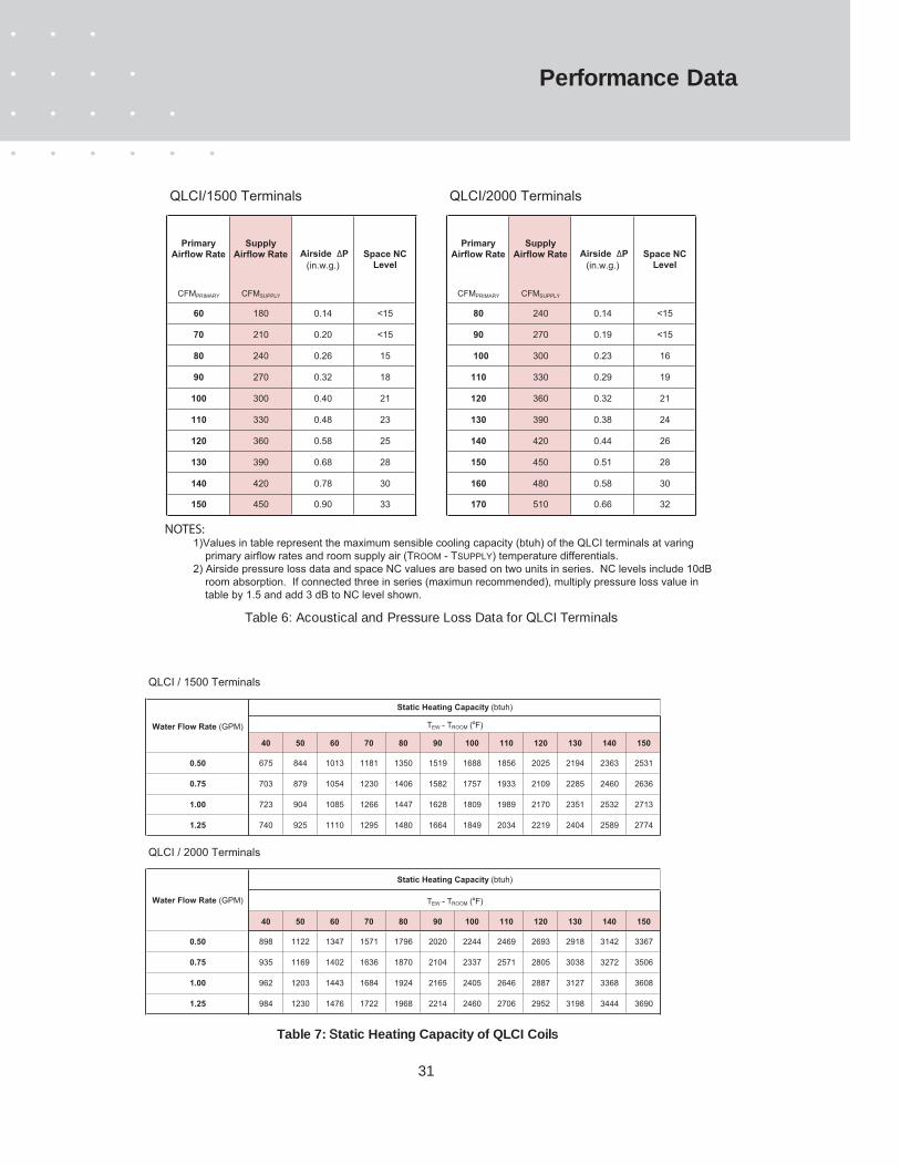
Table 7: Static Heating Capacity of QLCI Coils
Water Flow Rate (GPM)
Static Heating Capacity (btuh)
TEW - TROOM (ºF)
QLCI / 2000 Terminals
QLCI / 1500 Terminals
Water Flow Rate (GPM)
Static Heating Capacity (btuh)
TEW - TROOM (ºF)
Table 6: Acoustical and Pressure Loss Data for QLCI Terminals
140 420 0.78 30
130 390 0.68 28
120 360 0.58 25
110 330 0.48 23
100 300 0.40 21
90 270 0.32 18
80 240 0.26 15
70 210 0.20 <15
Airside DP(in.w.g.)
Space NC Level
60 180 0.14 <15
CFMPRIMARY CFMSUPPLY
PrimaryAirflow Rate
SupplyAirflow Rate
PrimaryAirflow Rate
SupplyAirflow Rate Airside DP
(in.w.g.)Space NC
Level
CFMPRIMARY CFMSUPPLY
80 240 0.14 <15
90 270 0.19 <15
100 300 0.23 16
110 330 0.29 19
120 360 0.32 21
130 390 0.38 24
0.51 28
140 420 0.44 26
170 510 0.66 32150 450 0.90 33
QLCI/1500 Terminals QLCI/2000 Terminals
160 480 0.58 30
150 450
1)Values in table represent the maximum sensible cooling capacity (btuh) of the QLCI terminals at varing primary airflow rates and room supply air (TROOM - TSUPPLY) temperature differentials.2) Airside pressure loss data and space NC values are based on two units in series. NC levels include 10dB room absorption. If connected three in series (maximun recommended), multiply pressure loss value in table by 1.5 and add 3 dB to NC level shown.
NOTES:

32
Performance Data
12 14 16 18 20 22
0.50 1.6 845 986 1126 1267 1408 1549
0.75 3.3 934 1090 1246 1401 1557 1713
1.00 5.6 975 1138 1300 1463 1625 1788
1.25 8.4 993 1159 1324 1490 1655 1821
0.50 1.6 923 1077 1230 1384 1538 1692
0.75 3.3 1025 1195 1366 1537 1708 1878
1.00 5.6 1072 1251 1430 1608 1787 1966
1.25 8.4 1094 1276 1458 1641 1823 2005
0.50 1.6 987 1152 1316 1481 1646 1810
0.75 3.3 1100 1283 1466 1650 1833 2016
1.00 5.6 1153 1345 1538 1730 1922 2114
1.25 8.4 1178 1374 1571 1767 1963 2160
0.50 1.6 1039 1212 1386 1559 1732 1905
0.75 3.3 1161 1354 1548 1741 1934 2128
1.00 5.6 1219 1422 1625 1828 2032 2235
1.25 8.4 1247 1454 1662 1870 2078 2285
0.50 1.6 1079 1259 1439 1619 1799 1978
0.75 3.3 1208 1409 1610 1812 2013 2214
1.00 5.6 1270 1482 1693 1905 2117 2328
1.25 8.4 1300 1517 1733 1950 2166 2383
0.50 1.6 1108 1292 1477 1662 1846 2031
0.75 3.3 1242 1449 1655 1862 2069 2276
1.00 5.6 1307 1525 1742 1960 2178 2396
1.25 8.4 1338 1561 1784 2007 2231 2554
0.50 1.6 1125 1313 1500 1688 1876 2063
0.75 3.3 1262 1473 1683 1894 2104 2315
1.00 5.6 1330 1551 1773 1994 2216 2437
1.25 8.4 1362 1589 1816 2043 2270 2497
0.50 1.6 1132 1321 1510 1698 1887 2076
0.75 3.3 1271 1482 1694 1906 2118 2329
1.00 5.6 1338 1561 1785 2008 2231 2454
1.25 8.4 1371 1600 1829 2057 2286 2514
0.50 1.6 1128 1316 1505 1693 1881 2069
0.75 3.3 1266 1477 1688 1899 2110 2321
1.00 5.6 1334 1566 1778 2000 2223 2445
1.25 8.4 1366 1594 1822 2049 2277 2505
0.50 1.6 1114 1300 1485 1671 1857 2042
0.75 3.3 1249 1457 1665 1873 2082 2290
1.00 5.6 1315 1534 1753 1972 2191 2410
1.25 8.4 1347 1571 1796 2020 2245 2469
60 180
120 360
110 330
100 300
70 210
Primary Airflow Rate(CFM)
Secondary Cooling (btuh)
T ROOM - T EW ( ºF)Water
Flow Rate(GPM)
Head Loss (ft. H2O)
Total Airflow Rate(CFM)
130 390
150 450
140
80
420
240
90 270
Table 8: Secondary Cooling Performance of QLCI/1500 Terminals for Basic Cooling Design Strategy (no condensation on integral cooling coil)
33
12 14 16 18 20 22
0.50 2.0 972 1134 1295 1457 1619 1781
0.75 4.1 1074 1254 1433 1611 1791 1970
1.00 7.0 1121 1309 1495 1682 1869 2056
1.25 10.5 1142 1333 1523 1714 1903 2094
0.50 2.0 1044 1219 1393 1567 1741 1915
0.75 4.1 1159 1352 1546 1739 1932 2125
1.00 7.0 1212 1415 1616 1818 2021 2222
1.25 10.5 1236 1442 1648 1854 2060 2267
0.50 2.0 1101 1283 1467 1650 1834 2017
0.75 4.1 1224 1427 1632 1835 2039 2244
1.00 7.0 1282 1495 1709 1923 2137 2349
1.25 10.5 1309 1526 1745 1963 2180 2399
0.50 2.0 1155 1348 1540 1732 1925 2117
0.75 4.1 1288 1502 1717 1931 2146 2361
1.00 7.0 1350 1576 1801 2026 2251 2476
1.25 10.5 1380 1610 1840 2070 2300 2530
0.50 2.0 1195 1394 1594 1793 1992 2191
0.75 4.1 1335 1557 1780 2002 2224 2447
1.00 7.0 1402 1635 1869 2102 2337 2570
1.25 10.5 1434 1672 1911 2151 2390 2628
0.50 2.0 1233 1439 1643 1849 2055 2260
0.75 4.1 1379 1609 1839 2069 2299 2529
1.00 7.0 1450 1692 1933 2175 2417 2659
1.25 10.5 1484 1731 1979 2226 2474 2721
0.50 2.0 1259 1469 1679 1888 2099 2308
0.75 4.1 1410 1646 1880 2115 2351 2585
1.00 7.0 1484 1731 1978 2225 2473 2720
1.25 10.5 1519 1772 2025 2278 2532 2785
0.50 2.0 1281 1495 1709 1922 2136 2349
0.75 4.1 1436 1676 1916 2155 2394 2634
1.00 7.0 1512 1764 2016 2269 2521 2773
1.25 10.5 1549 1808 2065 2324 2582 2841
0.50 2.0 1294 1510 1725 1941 2157 2372
0.75 4.1 1451 1694 1935 2178 2420 2662
1.00 7.0 1530 1784 2039 2293 2548 2803
1.25 10.5 1566 1827 2088 2349 2611 2872
0.50 2.0 1302 1518 1735 1953 2169 2386
0.75 4.1 1461 1704 1947 2191 2435 2677
1.00 7.0 1539 1795 2052 2308 2565 2821
1.25 10.5 1577 1839 2102 2364 2628 2890
170 510
160 480
150 450
140 420
130 390
120 360
110 330
100 300
90 270
80 240
Water Flow Rate
(GPM)
Head Loss (ft. H2O)
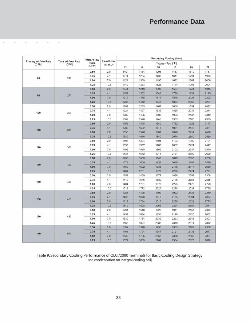
Secondary Cooling (btuh)
TROOM - TEW (ºF)Primary Airflow Rate
(CFM)Total Airflow Rate
(CFM)
Table 9: Secondary Cooling Performance of QLCI/2000 Terminals for Basic Cooling Design Strategy(no condensation on integral cooling coil)
Performance Data

34
Performance Data
18 20 22 24 26 28 30 32
0.50 1.6 1267 1408 1549 1690 1830 1971 2112 2253
0.75 3.3 1401 1557 1713 1868 2024 2180 2336 2491
1.00 5.6 1462 1625 1788 1950 2113 2275 2438 2600
1.25 8.4 1489 1655 1821 1986 2152 2317 2483 2648
0.50 1.6 1384 1538 1692 1846 2000 2153 2307 2461
0.75 3.3 1538 1708 1878 2049 2220 2391 2562 2732
1.00 5.6 1609 1787 1966 2144 2323 2502 2680 2859
1.25 8.4 1641 1823 2005 2187 2370 2552 2734 2916
0.50 1.6 1482 1646 1811 1975 2139 2304 2468 2633
0.75 3.3 1665 1843 2022 2200 2383 2566 2750 2933
1.00 5.6 1730 1922 2114 2306 2499 2691 2883 3075
1.25 8.4 1767 1963 2160 2356 2552 2749 2945 3141
0.50 1.6 1559 1732 1905 2078 2252 2425 2598 2771
0.75 3.3 1741 1934 2128 2321 2515 2708 2902 3095
1.00 5.6 1829 2032 2235 2438 2641 2844 3047 3251
1.25 8.4 1871 2078 2286 2493 2701 2909 3116 3324
0.50 1.6 1620 1799 1979 2158 2338 2518 2698 2878
0.75 3.3 1812 2013 2215 2416 2617 2818 3019 3221
1.00 5.6 1906 2117 2329 2540 2752 2693 3175 3387
1.25 8.4 1949 2166 2383 2600 2816 3033 3250 3466
0.50 1.6 1662 1846 2031 2215 2400 2585 2769 2954
0.75 3.3 1862 2069 2276 2483 2690 2897 3014 3311
1.00 5.6 1960 2178 2396 2614 2831 3049 3267 3485
1.25 8.4 2008 2231 2454 2677 2900 3123 3346 3569
0.50 1.6 1689 1876 2064 2251 2438 2626 2813 3001
0.75 3.3 1894 2104 2315 2525 2735 2946 3156 3367
1.00 5.6 1995 2216 2438 2659 2881 3102 3324 3545
1.25 8.4 2043 2270 2497 2724 2951 3178 3405 3632
0.50 1.6 1699 1887 2076 2264 2543 2642 2830 3019
0.75 3.3 1907 2118 2330 2541 2753 2965 3177 3388
1.00 5.6 2008 2231 2454 2677 2900 3123 3346 3569
1.25 8.4 2058 2286 2515 2743 2971 3200 3429 3757
0.50 1.6 1693 1881 2069 2257 2445 2633 2821 3009
0.75 3.3 1899 2110 2321 2532 2743 2954 3165 3376
1.00 5.6 2001 2223 2445 2667 2889 3112 3334 3556
1.25 8.4 2049 2277 2505 2733 2960 3188 3416 3644
0.50 1.6 1672 1857 2043 2228 2414 2599 2785 2970
0.75 3.3 1874 2082 2290 2498 2706 2914 3122 3331
1.00 5.6 1972 2191 2411 2630 2849 3068 3287 3506
1.25 8.4 2021 2245 2469 2693 2918 3142 3367 3591
Secondary Cooling (btuh)
TROOM - TEW (ºF)
Table 10: Secondary Sensible Cooling for QLCI /1500Terminals in a Condensing Design Strategy
Water Flow Rate
(GPM)
Head Loss (ft. H2O)
Primary Airflow Rate
(CFM)
150 450
140 410
130 390
120 360
110 330
100 300
90 270
80 240
70 210
60 180
Total Airflow Rate
(CFM)

35
18 20 22 24 26 28 30 32
0.50 2.0 1457 1619 1781 1944 2105 2267 2429 2591
0.75 4.1 1611 1791 1970 2148 2328 2507 2686 2865
1.00 7.0 1681 1869 2056 2243 2430 2616 2804 2990
1.25 10.5 1712 1903 2094 2284 2475 2665 2855 3045
0.50 2.0 1567 1741 1915 2090 2263 2438 2612 2785
0.75 4.1 1739 1932 2125 2318 2512 2705 2897 3090
1.00 7.0 1818 2021 2222 2424 2627 2828 3030 3233
1.25 10.5 1854 2060 2267 2473 2678 2884 3090 3296
0.50 2.0 1650 1834 2017 2200 2384 2567 2751 2934
0.75 4.1 1835 2039 2244 2447 2651 2855 3059 3264
1.00 7.0 1923 2137 2349 2563 2777 2991 3204 3418
1.25 10.5 1963 2180 2399 2617 2835 3053 3272 3489
0.50 2.0 1732 1925 2117 2502 2502 2694 2887 3080
0.75 4.1 1931 2146 2361 2790 2790 3004 3219 3434
1.00 7.0 2026 2251 2476 2701 2927 3151 3376 3602
1.25 10.5 2070 2300 2530 2760 2990 3220 3450 3680
0.50 2.0 1793 1992 2191 2390 2590 2789 2988 3187
0.75 4.1 2002 2224 2447 2669 2892 3114 3337 3559
1.00 7.0 2103 2337 2570 2804 3037 3271 3504 3739
1.25 10.5 2151 2390 2628 2867 3106 3345 3583 3823
0.50 2.0 1849 2055 2260 2466 2671 2876 3082 3288
0.75 4.1 2069 2299 2529 2759 2989 3219 3449 3678
1.00 7.0 2175 2417 2659 2900 3142 3383 3625 3867
1.25 10.5 2226 2474 2721 2968 3215 3463 3710 3957
0.50 2.0 1888 2099 2308 2519 2728 2938 3148 3358
0.75 4.1 2115 2351 2585 2821 3056 3290 3526 3761
1.00 7.0 2225 2473 2720 2967 3214 3462 3709 3956
1.25 10.5 2278 2532 2785 3038 3291 3544 3797 4051
0.50 2.0 1922 2136 2349 2562 2776 2990 3203 3417
0.75 4.1 2155 2394 2634 2873 3113 3352 3591 3831
1.00 7.0 2269 2521 2773 3025 3276 3529 3781 4033
1.25 10.5 2324 2582 2841 3098 3357 3614 3873 4131
0.50 2.0 1941 2157 2372 2596 2812 3028 3244 3460
0.75 4.1 2178 2420 2662 2912 3154 3397 3640 3882
1.00 7.0 2293 2548 2803 3067 3322 3579 3834 4089
1.25 10.5 2349 2611 2872 3143 3404 3666 3928 4191
0.50 2.0 1953 2169 2386 2602 2820 3037 3253 3471
0.75 4.1 2191 2435 2677 2921 3165 3407 3651 3895
1.00 7.0 2308 2565 2821 3076 3333 3589 3846 4102
1.25 10.5 2364 2628 2890 3152 3416 3678 3941 4203
170 510
160 480
150 450
140 420
130 390
120 360
110 330
100 300
Secondary Cooling (btuh)
TROOM - TEW (ºF)
90 270
80 240
Primary Airflow Rate(CFM)
Total Airflow Rate(CFM)
Water Flow Rate
(GPM)
Head Loss (ft. H2O)
Table 11: Secondary Sensible Cooling for QLCI/2000 Terminals in a Condensing Design Strategy(condensation on integral cooling coil dehumidifies recirculated air)
Performance Data

36
Performance Data
50 70 90 110 130
0.75 1.1 2053 2874 3595 4516 5337
1.00 1.8 2118 2965 3812 4659 5506
1.25 2.7 2140 2996 3852 4708 5564
1.50 3.8 2169 3037 3905 4772 5640
0.75 1.1 2263 3169 4074 4979 5885
1.00 1.8 2338 3273 4208 5143 6079
1.25 2.7 2365 3310 4256 5202 6148
1.50 3.8 2398 3358 4317 5277 6236
0.75 1.1 2440 3416 4392 5369 6345
1.00 1.8 2524 3533 4542 5552 6561
1.25 2.7 2554 3576 4598 5619 6641
1.50 3.8 2592 3629 4666 5702 6739
0.75 1.1 2584 3618 4652 5686 6720
1.00 1.8 2675 3745 4815 5885 6955
1.25 2.7 2709 3793 4877 5961 7044
1.50 3.8 2751 3851 4951 6051 7151
0.75 1.1 2697 3776 4854 5933 7012
1.00 1.8 2794 3911 5028 6146 7263
1.25 2.7 2831 3963 5095 6227 7359
1.50 3.8 2874 4024 5174 6324 7474
0.75 1.1 2778 3889 5000 6112 7223
1.00 1.8 2879 4031 5182 6334 7485
1.25 2.7 2918 4085 5253 6420 7587
1.50 3.8 2964 4150 5335 6521 7707
0.75 1.1 2828 3960 5091 6222 7353
1.00 1.8 2932 4105 5278 6450 7623
1.25 2.7 2973 4162 5351 6540 7729
1.50 3.8 3020 4228 5436 6644 7852
0.75 1.1 2848 3987 5126 6265 7405
1.00 1.8 2953 4134 5315 6496 7677
1.25 2.7 2994 4191 5389 6586 7784
1.50 3.8 3042 4258 5475 6692 7908
0.75 1.1 2837 3972 5107 6242 7376
1.00 1.8 2941 4118 5294 6471 7648
1.25 2.7 2982 4175 5368 6561 7754
1.50 3.8 3030 4241 5453 6665 7877
0.75 1.1 2796 3914 5037 6151 7269
1.00 1.8 2898 4057 5216 6375 7534
1.25 2.7 2737 4112 5287 6462 7637
1.50 3.8 1984 4177 5371 6564 7758
60 180
150 450
140 420
130 390
120 360
110 330
100 300
90 270
80 240
TEW - TROOM (ºF)
70 210
Primary Airflow Rate(CFM)
Supply Airflow Rate(CFM)
Water Flow (GPM)
Head Loss(ft. H2O)
Secondary Heating (btuh)
Table 12: Secondary Heating Performance of QLCI/1500 Terminals(4 pipe coil configuration)

37
Performance Data
50 70 90 110 1300.75 1.3 2361 3305 4134 5193 61381.00 2.2 2436 3410 4384 5358 63321.25 3.4 2461 3445 4430 5414 63991.50 4.7 2494 3493 4491 5488 64860.75 1.1 2558 3580 4603 5627 66491.00 1.8 2642 3697 4754 5811 68671.25 2.7 2670 3739 4807 5875 69441.50 3.8 2708 3793 4876 5959 70430.75 1.1 2709 3793 4877 5960 70441.00 1.8 2800 3920 5040 6161 72811.25 2.7 2834 3966 5100 6233 73671.50 3.8 2875 4024 5174 6324 74740.75 1.1 2860 4004 5147 6292 74361.00 1.8 2959 4142 5326 6509 76921.25 2.7 2995 4193 5391 6590 77871.50 3.8 3039 4256 5472 6687 79030.75 1.1 2972 4161 5350 6539 77281.00 1.8 3076 4307 5537 6768 79981.25 2.7 3115 4362 5609 6855 81011.50 3.8 3164 4429 5694 6959 82240.75 1.1 3079 4310 5541 6772 80041.00 1.8 3188 4463 5739 7014 82891.25 2.7 3230 4523 5814 7107 83981.50 3.8 3280 4592 5904 7216 85280.75 1.1 3152 4414 5674 6936 81961.00 1.8 3266 4572 5880 7186 84931.25 2.7 3311 4635 5958 7283 86071.50 3.8 3443 4707 6051 7397 81200.75 1.1 3215 4502 5788 7075 83611.00 1.8 3333 4667 6000 7332 86661.25 2.7 3379 4730 6081 7434 87851.50 3.8 3432 4805 6178 7551 89230.75 1.1 3252 4554 5855 7155 84561.00 1.8 3372 4721 6070 7418 87661.25 2.7 3419 4786 6154 7521 88881.50 3.8 3473 4862 6251 7641 90300.75 1.1 3273 4583 5893 7201 85111.00 1.8 3394 4752 6109 7467 88241.25 2.7 3441 4817 6194 7570 89471.50 3.8 3496 4894 6293 7691 9090
150 450
140 420
130
170 510
160 480
390
120 360
110 330
100 300
Secondary Heating (btuh)TEW - TROOM (ºF)
90 270
80 240
Primary Airflow Rate(CFM)
Supply Airflow Rate
(CFM)
Water Flow (GPM)
Head Loss(ft. H2O)
Table 13: Secondary Heating Performance of QLCI/2000 Terminals(4 pipe coil configuration)
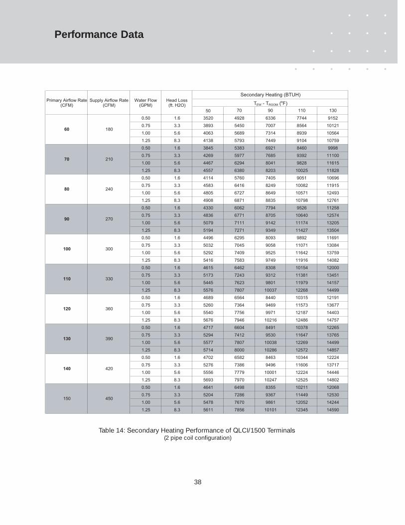
38
50 70 90 110 130
0.50 1.6 3520 4928 6336 7744 9152
0.75 3.3 3893 5450 7007 8564 10121
1.00 5.6 4063 5689 7314 8939 10564
1.25 8.3 4138 5793 7449 9104 10759
0.50 1.6 3845 5383 6921 8460 9998
0.75 3.3 4269 5977 7685 9392 11100
1.00 5.6 4467 6294 8041 9828 11615
1.25 8.3 4557 6380 8203 10025 11828
0.50 1.6 4114 5760 7405 9051 10696
0.75 3.3 4583 6416 8249 10082 11915
1.00 5.6 4805 6727 8649 10571 12493
1.25 8.3 4908 6871 8835 10798 12761
0.50 1.6 4330 6062 7794 9526 11258
0.75 3.3 4836 6771 8705 10640 12574
1.00 5.6 5079 7111 9142 11174 13205
1.25 8.3 5194 7271 9349 11427 13504
0.50 1.6 4496 6295 8093 9892 11691
0.75 3.3 5032 7045 9058 11071 13084
1.00 5.6 5292 7409 9525 11642 13759
1.25 8.3 5416 7583 9749 11916 14082
0.50 1.6 4615 6462 8308 10154 12000
0.75 3.3 5173 7243 9312 11381 13451
1.00 5.6 5445 7623 9801 11979 14157
1.25 8.3 5576 7807 10037 12268 14499
0.50 1.6 4689 6564 8440 10315 12191
0.75 3.3 5260 7364 9469 11573 13677
1.00 5.6 5540 7756 9971 12187 14403
1.25 8.3 5676 7946 10216 12486 14757
0.50 1.6 4717 6604 8491 10378 12265
0.75 3.3 5294 7412 9530 11647 13765
1.00 5.6 5577 7807 10038 12269 14499
1.25 8.3 5714 8000 10286 12572 14857
0.50 1.6 4702 6582 8463 10344 12224
0.75 3.3 5276 7386 9496 11606 13717
1.00 5.6 5556 7779 10001 12224 14446
1.25 8.3 5693 7970 10247 12525 14802
0.50 1.6 4641 6498 8355 10211 12068
0.75 3.3 5204 7286 9367 11449 12530
1.00 5.6 5478 7670 9861 12052 14244
1.25 8.3 5611 7856 10101 12345 14590
150 450
140 420
130 390
120 360
110 330
100 300
90 270
80 240
70 210
Water Flow (GPM)
Head Loss(ft. H2O)
Secondary Heating (BTUH)
TEW - TROOM (ºF)Primary Airflow Rate
(CFM)Supply Airflow Rate
(CFM)
60 180
Table 14: Secondary Heating Performance of QLCI/1500 Terminals(2 pipe coil configuration)
Performance Data

39
50 70 90 110 1300.50 1.6 4048 5667 7286 8906 105250.75 3.3 4477 6268 8058 9849 116391.00 5.6 4672 6542 8411 10280 121491.25 8.3 4759 6662 8566 10470 123730.50 1.6 4353 6094 7835 9576 113170.75 3.3 4829 6761 8692 10624 125561.00 5.6 5051 7071 9091 11111 131321.25 8.3 5151 7211 9271 11331 133920.50 1.6 4584 6418 8252 10086 119200.75 3.3 5099 7138 9178 11217 132561.00 5.6 5341 7477 9613 11750 138861.25 8.3 5429 7633 9814 11995 141750.50 1.6 4812 6737 8661 10586 125110.75 3.3 5365 7511 9657 11802 139481.00 5.6 5628 7879 10130 12381 146331.25 8.3 5751 8051 10351 12651 149520.50 1.6 4980 6971 8963 10955 129470.75 3.3 5561 7787 10011 12236 144601.00 5.6 5841 8178 10513 12850 151861.25 8.3 5973 8362 10751 13141 155300.50 1.6 5137 8047 9246 11301 133560.75 3.3 5748 8459 10345 12644 149431.00 5.6 6042 8459 10876 13293 157101.25 8.3 6184 8656 11130 13603 160760.50 1.6 5246 7344 9443 11541 136390.75 3.3 5877 8226 10577 12927 152781.00 5.6 6182 8655 11127 13601 160741.25 8.3 6330 8862 11393 13925 164570.50 1.6 5338 7474 9609 11745 138810.75 3.3 5986 8380 10774 13169 155631.00 5.6 6301 8822 11342 13863 163841.25 8.3 6455 9037 11618 14200 167820.50 2.6 5392 7549 9706 11862 140200.75 4.4 6049 8469 10889 13309 157291.00 6.6 6371 8919 11467 14015 165631.25 9.2 6527 9138 11748 14359 169710.50 1.6 5422 7591 9761 11930 140990.75 3.3 6086 8519 10954 13388 158221.00 5.6 6410 8973 11538 14102 166661.25 8.3 6568 9195 11823 14450 17078
170 510
160 480
150 450
140 420
130 390
120 360
110 330
100 300
Secondary Heating (BTUH)TEW - TROOM (ºF)
90 270
80 240
Primary Airflow Rate(CFM)
Supply Airflow Rate
(CFM)
Water Flow (GPM)
Head Loss(ft. H2O)
Table 15: Secondary Heating Performance of QLCI/2000 Terminals(2 pipe coil configuration)
Performance Data

40
Design Procedures
of primary air that might eliminate the needfor condensation. It also suggests severalmodifications which may eliminate the needfor such condensation. If condensation isnecessary to achieve design space humidityratios, proceed directly to step 7 at this time.
e) QPRI will be the greatest of the valuescalculated in steps b) through d) above.
4. Determine the minimum number of QLCIterminals and their individual contribution to the(sensible) cooling of the space.
a) Determine the maximum QLCI airflow ratethat conforms to the design NC (see table 6).
b) Divide the primary airflow (QPRI) determinedin step 3e) by this value to determine theminimum number of terminals required.
c) Confirm that the required terminals willphysically fit along the classroom facade.
d) Determine the required sensible coolingcontribution (qQLCI) of each terminal:
qSENS = ESHG / (No. QLCI terminals)
e) Determine the primary air (qPRI) and requiredsecondary (qSEC) sensible contributions:
5. Terminal design and selection for a standard(non-condensing) design strategy.
a) Identify an appropriate entering chilled watertemperature (TEW). TEW must be above thespace dew point temperature.
b) Refer to the appropriate table (8 or 9) toidentify a chilled water temperature and flowrate that produces the required secondarycooling. If this (qSEC) cannot be accomplishedat the airflow rate and such a chilled watersupply temperature, condensation will berequired to achieve the desired sensiblespace cooling. Proceed to step7f) on thenext page.
6. The cooling design is complete, proceed to theheating design procedures on the next page.
COOLING DESIGN PROCEDURES
1. Identify the space cooling design parameters.a) Identify the outdoor design (DB and WB)
temperatures and humidity ratio (WOA)b) Identify the design summer temperature
(T ROOM) and humidity ratio (WROOM) and theresultant space dew point temperature
c) Identify the maximum space NC level
2. Identify the space loads and ventilation rate.a) Identify the total sensible heat gain (TSHG)b) Space effective sensible heat gain (ESHG):
ESHG = Total sensible heat gain x 0.75
c) Identify the space latent heat gain (LHG)
d) Calculate the space sensible heat ratio:
SHR = TSHG / (TSHG + LHG)
e) Identify the minimum ventilation rate (QVENT)
3. Determine the supply and primary airflowrequirements.
a) Select an appropriate room to supply airtemperature differential (see table 4).
b) Determine the supply airflow rate (CFM)required to satisfy the space sensible load:
QSENS = ESHG / [1.1 x (T ROOM - T SUPPLY)]
QPRI = QSENS/3
c) Determine the minimum primary airflow ratethat will provide adequate space ventilation
QPRI >QVENT
d) Identify the primary airflow rate that would be required to satisfy the space latent loadwithout condensation on the QLCI coils:
QPRl = LHG / [0.68 x (WROOM - WPRI)]
If this primary airflow rate exceeds thegreater value of QPRl from steps a) and b), adesign employing condensation on the QLCIcoils may be necessary. Table 2 on page 13can be used to estimate the excess amount
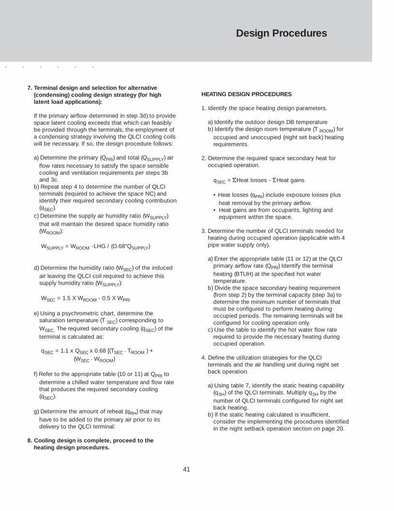
41
Design Procedures
7. Terminal design and selection for alternative (condensing) cooling design strategy (for high latent load applications):
If the primary airflow determined in step 3d) to provide space latent cooling exceeds that which can feasibly be provided through the terminals, the employment of a condensing strategy involving the QLCI cooling coils will be necessary. If so, the design procedure follows:
a) Determine the primary (QPRI) and total (QSUPPLY) airflow rates necessary to satisfy the space sensible cooling and ventilation requirements per steps 3b and 3c.
b) Repeat step 4 to determine the number of QLCI terminals (required to achieve the space NC) and identify their required secondary cooling contribution(qSEC).
c) Determine the supply air humidity ratio (WSUPPLY) that will maintain the desired space humidity ratio (WROOM):
WSUPPLY = WROOM -LHG / (O.68*QSUPPLY)
d) Determine the humidity ratio (WSEC) of the induced air leaving the QLCI coil required to achieve this supply humidity ratio (WSUPPLY):
WSEC = 1.5 X WROOM - 0.5 X WPRI
e) Using a psychrometric chart, determine thesaturation temperature (T SEC) corresponding to WSEC. The required secondary cooling (qSEC) of the terminal is calculated as:
qSEC = 1.1 x QSEC x 0.68 [(TSEC - TROOM ) +(WSEC - WROOM)
f) Refer to the appropriate table (10 or 11) at QPRI to determine a chilled water temperature and flow rate that produces the required secondary cooling (qSEC).
g) Determine the amount of reheat (qRH) that may have to be added to the primary air prior to its delivery to the QLCI terminal:
8. Cooling design is complete, proceed to theheating design procedures.
HEATING DESIGN PROCEDURES
1. Identify the space heating design parameters.
a) Identify the outdoor design DB temperatureb) Identify the design room temperature (T ROOM) for
occupied and unoccupied (night set back) heating requirements.
2. Determine the required space secondary heat foroccupied operation.
qSEC = SHeat losses - SHeat gains
• Heat losses (qPRI) include exposure losses plus heat removal by the primary airflow.
• Heat gains are from occupants, lighting and equipment within the space.
3. Determine the number of QLCI terminals needed for heating during occupied operation (applicable with 4 pipe water supply only).
a) Enter the appropriate table (11 or 12) at the QLCI primary airflow rate (QPRl) Identify the terminal heating (BTUH) at the specified hot water temperature.
b) Divide the space secondary heating requirement (from step 2) by the terminal capacity (step 3a) to determine the minimum number of terminals that must be configured to perform heating during occupied periods. The remaining terminals will be configured for cooling operation only.
c) Use the table to identify the hot water flow rate required to provide the necessary heating during occupied operation.
4. Define the utilization strategies for the QLCI terminals and the air handling unit during night set back operation.
a) Using table 7, identify the static heating capability (qSH) of the QLCI terminals. Multiply qSH by the number of QLCI terminals configured for night set back heating.
b) If the static heating calculated is insufficient,consider the implementing the procedures identified in the night setback operation section on page 20.
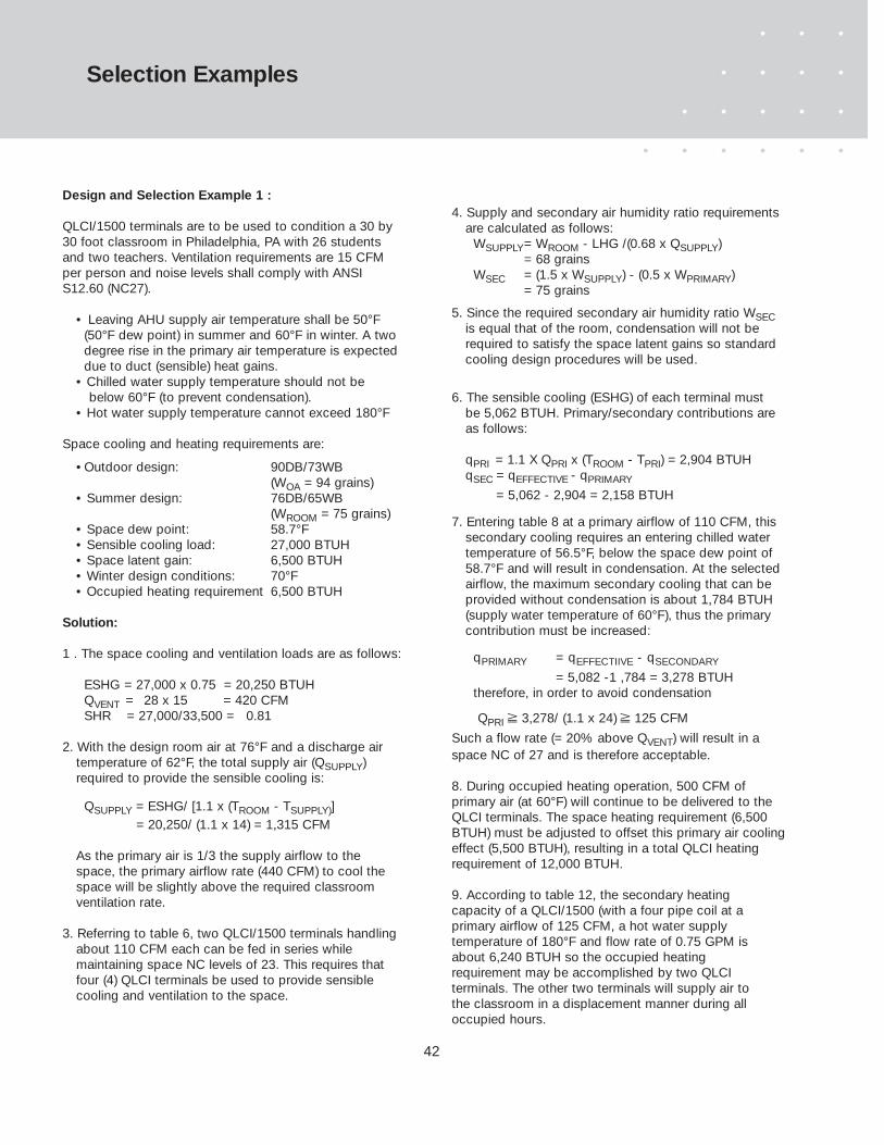
42
Selection Examples
Design and Selection Example 1 :
QLCI/1500 terminals are to be used to condition a 30 by30 foot classroom in Philadelphia, PA with 26 studentsand two teachers. Ventilation requirements are 15 CFMper person and noise levels shall comply with ANSIS12.60 (NC27).
• Leaving AHU supply air temperature shall be 50°F(50°F dew point) in summer and 60°F in winter. A two degree rise in the primary air temperature is expected due to duct (sensible) heat gains.
• Chilled water supply temperature should not bebelow 60°F (to prevent condensation).
• Hot water supply temperature cannot exceed 180°F
Space cooling and heating requirements are:
•Outdoor design: 90DB/73WB(WOA = 94 grains)
• Summer design: 76DB/65WB(WROOM = 75 grains)
• Space dew point: 58.7°F• Sensible cooling load: 27,000 BTUH• Space latent gain: 6,500 BTUH• Winter design conditions: 70°F• Occupied heating requirement 6,500 BTUH
Solution:
1 . The space cooling and ventilation loads are as follows:
ESHG = 27,000 x 0.75 = 20,250 BTUHQVENT = 28 x 15 = 420 CFMSHR = 27,000/33,500 = 0.81
2. With the design room air at 76°F and a discharge airtemperature of 62°F, the total supply air (QSUPPLY)required to provide the sensible cooling is:
QSUPPLY = ESHG/ [1.1 x (TROOM - TSUPPLY)]= 20,250/ (1.1 x 14) = 1,315 CFM
As the primary air is 1/3 the supply airflow to thespace, the primary airflow rate (440 CFM) to cool thespace will be slightly above the required classroomventilation rate.
3. Referring to table 6, two QLCI/1500 terminals handling about 110 CFM each can be fed in series while maintaining space NC levels of 23. This requires thatfour (4) QLCI terminals be used to provide sensible cooling and ventilation to the space.
4. Supply and secondary air humidity ratio requirements are calculated as follows:
WSUPPLY= WROOM - LHG /(0.68 x QSUPPLY)= 68 grains
WSEC = (1.5 x WSUPPLY) - (0.5 x WPRIMARY)= 75 grains
5. Since the required secondary air humidity ratio WSECis equal that of the room, condensation will not be required to satisfy the space latent gains so standard cooling design procedures will be used.
6. The sensible cooling (ESHG) of each terminal mustbe 5,062 BTUH. Primary/secondary contributions areas follows:
qPRI = 1.1 X QPRI x (TROOM - TPRI) = 2,904 BTUHqSEC = qEFFECTIVE - qPRIMARY
= 5,062 - 2,904 = 2,158 BTUH
7. Entering table 8 at a primary airflow of 110 CFM, thissecondary cooling requires an entering chilled watertemperature of 56.5°F, below the space dew point of58.7°F and will result in condensation. At the selected airflow, the maximum secondary cooling that can be provided without condensation is about 1,784 BTUH (supply water temperature of 60°F), thus the primary contribution must be increased:
qPRlMARY = qEFFECTIIVE - qSECONDARY
= 5,082 -1 ,784 = 3,278 BTUHtherefore, in order to avoid condensation
QPRI ≥ 3,278/ (1.1 x 24) ≥ 125 CFM
Such a flow rate (= 20% above QVENT) will result in aspace NC of 27 and is therefore acceptable.
8. During occupied heating operation, 500 CFM ofprimary air (at 60°F) will continue to be delivered to theQLCI terminals. The space heating requirement (6,500BTUH) must be adjusted to offset this primary air coolingeffect (5,500 BTUH), resulting in a total QLCI heatingrequirement of 12,000 BTUH.
9. According to table 12, the secondary heatingcapacity of a QLCI/1500 (with a four pipe coil at aprimary airflow of 125 CFM, a hot water supplytemperature of 180°F and flow rate of 0.75 GPM isabout 6,240 BTUH so the occupied heatingrequirement may be accomplished by two QLCIterminals. The other two terminals will supply air tothe classroom in a displacement manner during alloccupied hours.
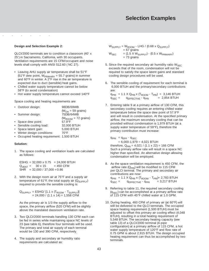
43
Design and Selection Example 2:
QLCI/2000 terminals are to condition a classroom (40’ x25’) in Sacramento, Califomia, with 30 occupants.Ventilation requirements are 15 CFM/occupant and noiselevels shall comply with ANSI S12.60 ( NC 27).
• Leaving AHU supply air temperature shall be 51°F(51°F dew point, WPRIMARY = 55.7 grains) in summerand 60°F in winter. A 2°F rise in the air temperature isexpected due to duct (sensible) heat gains.
• Chilled water supply temperature cannot be below58°F (to avoid condensation)
• Hot water supply temperature cannot exceed 140°F
Space cooling and heating requirements are:
• Outdoor design: 98DB/69WB(WOA = 59 grains)
• Summer design: 75DB/64WB(WROOM = 72 grains)
• Space dew point: 57.9°F• Sensible cooling load: 32,000 BTUH• Space latent gain: 5,000 BTUH• Winter design conditions: 70°F• Occupied heating requirement: 1,500 BTUH
Solution:
1. The space cooling and ventilation loads are calculatedas follows:
ESHG = 32,000 x 0.75 = 24,000 BTUHQVENT = 30 x 15 = 450 CFMSHR = 32,000 / 37,000 =0.86
2. With the design room air at 75°F and a supply airtemperature of 61°F, the total supply air (QSUPPLY)required to provide the sensible cooling is:
QSUPPLY = ESHG/ [1.1 x (TROOM - TSUPPLY)]= 24,000 / (1.1 x 14) = 1,558 CFM
As the primary air is 1/3 the supply airflow to thespace, the primary airflow (520 CFM) will be slightlyabove the mandated dassroom ventilation rate.
3. Two QLCI/2000 terminals handling 130 CFM each canbe fed in series while maintaining space NC levels of 23 (see table 6), therefore four terminals will be used. The primary and total air supply of each terminal would be 130 and 390 CFM, respectively.
4. The supply and secondary air humidity ratiorequirements are calculated as:
WSUPPLY = WROOM - LHG / (0.68 x QSUPPLY)= 67 grains
WSEC = (1.5 X WSUPPLY) - (0.5 x WPRIMARY)= 73 grains
5. Since the required secondary air humidity ratio WSECexceeds that of the room, condensation will not be required to satisfy the space latent gains and standard cooling design procedures will be used.
6. The sensible cooling of requirement for each terminal is6,000 BTUH and the primary/secondary contributions
are:qPRI = 1.1 X QPRI x (TROOM - TPRI) = 3,146 BTUHqSEC = qEFFECTIVE - qPRI = 2,854 BTUH
7. Entering table 9 at a primary airflow of 130 CFM, thissecondary cooling requires an entering chilled watertemperature below the space dew point of 57.9°Fand will result in condensation. At the specified primaryairflow, the maximum secondary cooling that can be provided without condensation is 1,979 BTUH (at a supply water temperature of 59°F), therefore the primary contribution must increase:
qPRI = qEFF - qSEC
= 6,000-1,979 = 4,021 BTUHtherefore, QPRI = 4,021 / (1.1 x 22) = 166 CFMSuch a primary airflow rate will result in a space NChigher than specified. An alternative design allowingcondensation will be employed.
8. As the space ventilation requirement is 450 CFM, theairflow rate (QPRI) will be modified to 115 CFM
per QLCI termnal. The primary and secondary air contributions are now:qPRI = 1.1 X QPRI x (TROOM - TPRI)= 2,783 BTUHqSEC = qEFFECTIVE - qPRI = 3,217 BTUH
9. Referring to tabte 11, the required secondary cooling(qSEC) can be accomplished at a primary airflow rateof 115 CFM with 45°F chilled water at 1.0 GPM.
10. During heating, 460 CFM of primary air (at 60°F) willstill be delivered to the QLCI terminals. The occupiedspace heating requirement (1,500 BTUH) must beadjusted to offset this primary air cooling effect (4,048 BTUH), resulting in a total heating requirement of 5,548 BTUH. The secondary heating capacity (see table 13) of a QLCI/2000 terminal (4-pipe configuration) at a primary airflow of 115 CFM, a hot water supply temperature of 120°F and flow rate of 0.75 GPM is about 2,915 BTUH. The design occupied heating requirement can thus be accomplished by two terminals.
Selection Examples
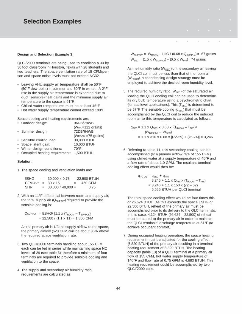
44
Design and Selection Example 3:
QLCI/2000 terminals are being used to condition a 30 by30 foot classroom in Houston, Texas with 28 students andtwo teachers. The space ventilation rate of 15 CFM/per-son and space noise levels must not exceed NC32.
• Leaving AHU supply air temperature shall be 50°F (50°F dew point) in summer and 60°F in winter. A 2°F rise in the supply air temperature is expected due to duct (sensible) heat gains and the minimum supply airtemperature to the space is 61°F.
• Chilled water temperatures must be at least 45°F• Hot water supply temperature cannot exceed 180°F
Space cooling and heating requirements are:• Outdoor design: 96DB/79WB
(WOA =122 grains)• Summer design: 72DB/64WB
(WROOM =75 grains)• Sensible cooling load: 30,000 BTUH • Space latent gain: 10,000 BTUH• Winter design conditions: 70°F• Occupied heating requirement: 1,500 BTUH
Solution:
1. The space cooling and ventilation loads are:
ESHG = 30,000 x 0.75 = 22,500 BTUHCFMVENT = 30 x 15 = 450 CFMSHR = 30,000 / 40,000 = 0.75
2. With an 11°F differential between room and supply air,the total supply air (QSUPPLY) required to provide the sensible cooling is:
QSUPPLY = ESHG/ [1.1 x (TROOM – TSUPPLY)]= 22,500 / (1.1 x 11) = 1,800 CFM
As the primary air is 1/3 the supply airflow to the space,the primary airflow (620 CFM) will be about 35% abovethe required space ventilation rate.
3. Two QLCI/2000 terminals handling about 155 CFM each can be fed in series while maintaining space NC levels of 29 (see table 6), therefore a minimum of four terminals are required to provide sensible cooling and ventilation to the space.
4. The supply and secondary air humidity ratio requirements are calculated as:
WSUPPLY = WROOM - LHG / (0.68 x QSUPPLY) = 67 grains
WSEC = (1.5 x WSUPPLY) – (0.5 x WPRI)= 74 grains
As the humidity ratio (WSEC) of the secondary air leavingthe QLCI coil must be less than that of the room air (WROOM), a ccondensing design strategy must be employed to achieve the desired room humidity level.
5. The required humidity ratio (WSEC) of the saturated air leaving the QLCI cooling coil can be used to determineits dry bulb temperature using a psychrometric chart (for sea level applications). This (TSEC) is determined to be 57°F. The sensible cooling (qSEC) that must be accomplished by the QLCI coil to reduce the induced room air to this temperature is calculated as follows:
qSEC = 1.1 x QSEC x 0.68 x [(TROOM – TSEC)+(WROOM – WSEC)]
= 1.1 x 310 x 0.68 x [(72-59) + (75-74)] = 3,246
6. Referring to table 11, this secondary cooling can be accomplished (at a primary airflow rate of 155 CFM) using chilled water at a supply temperature of 45°F anda flow rate of about 1.0 GPM. The resultant terminal cooling effect would then be:
qTOTAL = qSEC + qPRI
= 3,246 + 1.1 x QPRI x (TROOM – TPRI)= 3,246 + 1.1 x 150 x (72 – 52)= 6,656 BTUH per QLCI terminal
The total space cooling effect would be four times this or 26,624 BTUH. As this exceeds the space ESHG of 22,500 BTUH, reheat of the primary air must be accomplished prior to its delivery to the QLCI terminals.In this case, 4,124 BTUH (26,624 – 22,500) of reheat must be added to the primary air in order to maintain the QLCI terminals’ discharge temperature at 61°F (to achieve occupant comfort).
7. During occupied heating operation, the space heating requirement must be adjusted for the cooling effect (6,820 BTUH) of the primary air resulting in a terminal heating requirement of 8,320 BTUH. The heating capacity (table 13) of a QLCI terminal at a primary airflow of 155 CFM, hot water supply temperature of 140°F and flow rate of 0.75 GPM is 4,683 BTUH. This heating requirement could be accomplished by twoQLCI/2000 coils.
Selection Examples
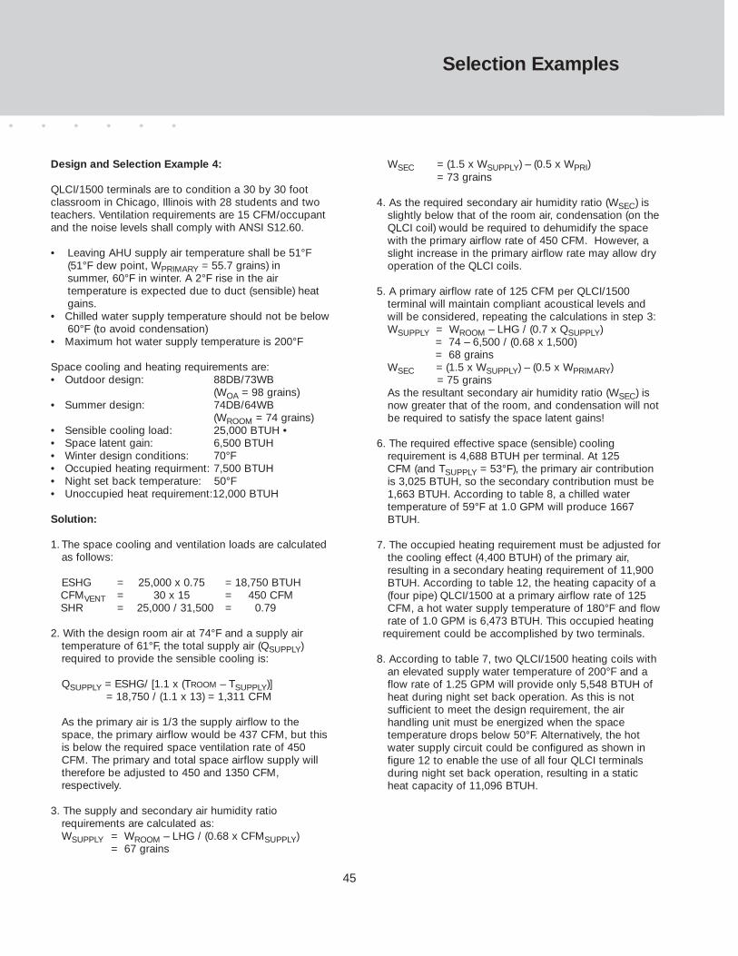
45
Selection Examples
Design and Selection Example 4:
QLCI/1500 terminals are to condition a 30 by 30 footclassroom in Chicago, Illinois with 28 students and twoteachers. Ventilation requirements are 15 CFM/occupantand the noise levels shall comply with ANSI S12.60.
• Leaving AHU supply air temperature shall be 51°F (51°F dew point, WPRIMARY = 55.7 grains) in summer, 60°F in winter. A 2°F rise in the air temperature is expected due to duct (sensible) heat gains.
• Chilled water supply temperature should not be below60°F (to avoid condensation)
• Maximum hot water supply temperature is 200°F
Space cooling and heating requirements are:• Outdoor design: 88DB/73WB
(WOA = 98 grains)• Summer design: 74DB/64WB
(WROOM = 74 grains)• Sensible cooling load: 25,000 BTUH •• Space latent gain: 6,500 BTUH• Winter design conditions: 70°F• Occupied heating requirment: 7,500 BTUH• Night set back temperature: 50°F • Unoccupied heat requirement:12,000 BTUH
Solution:
1. The space cooling and ventilation loads are calculated as follows:
ESHG = 25,000 x 0.75 = 18,750 BTUHCFMVENT = 30 x 15 = 450 CFMSHR = 25,000 / 31,500 = 0.79
2. With the design room air at 74°F and a supply air temperature of 61°F, the total supply air (QSUPPLY) required to provide the sensible cooling is:
QSUPPLY = ESHG/ [1.1 x (TROOM – TSUPPLY)] = 18,750 / (1.1 x 13) = 1,311 CFM
As the primary air is 1/3 the supply airflow to the space, the primary airflow would be 437 CFM, but this is below the required space ventilation rate of 450 CFM. The primary and total space airflow supply will therefore be adjusted to 450 and 1350 CFM, respectively.
3. The supply and secondary air humidity ratiorequirements are calculated as:WSUPPLY = WROOM – LHG / (0.68 x CFMSUPPLY)
= 67 grains
WSEC = (1.5 x WSUPPLY) – (0.5 x WPRI)= 73 grains
4. As the required secondary air humidity ratio (WSEC) is slightly below that of the room air, condensation (on theQLCI coil) would be required to dehumidify the space with the primary airflow rate of 450 CFM. However, a slight increase in the primary airflow rate may allow dry operation of the QLCI coils.
5. A primary airflow rate of 125 CFM per QLCI/1500 terminal will maintain compliant acoustical levels and will be considered, repeating the calculations in step 3:WSUPPLY = WROOM – LHG / (0.7 x QSUPPLY)
= 74 – 6,500 / (0.68 x 1,500)= 68 grains
WSEC = (1.5 x WSUPPLY) – (0.5 x WPRIMARY)= 75 grains
As the resultant secondary air humidity ratio (WSEC) is now greater that of the room, and condensation will notbe required to satisfy the space latent gains!
6. The required effective space (sensible) cooling requirement is 4,688 BTUH per terminal. At 125 CFM (and TSUPPLY = 53°F), the primary air contribution is 3,025 BTUH, so the secondary contribution must be 1,663 BTUH. According to table 8, a chilled water temperature of 59°F at 1.0 GPM will produce 1667 BTUH.
7. The occupied heating requirement must be adjusted forthe cooling effect (4,400 BTUH) of the primary air, resulting in a secondary heating requirement of 11,900 BTUH. According to table 12, the heating capacity of a (four pipe) QLCI/1500 at a primary airflow rate of 125 CFM, a hot water supply temperature of 180°F and flowrate of 1.0 GPM is 6,473 BTUH. This occupied heating
requirement could be accomplished by two terminals.
8. According to table 7, two QLCI/1500 heating coils with an elevated supply water temperature of 200°F and a flow rate of 1.25 GPM will provide only 5,548 BTUH of heat during night set back operation. As this is not sufficient to meet the design requirement, the air handling unit must be energized when the space temperature drops below 50°F. Alternatively, the hot water supply circuit could be configured as shown in figure 12 to enable the use of all four QLCI terminals during night set back operation, resulting in a static heat capacity of 11,096 BTUH.
46
Notes Regarding Filter Option:
Although MERV-8 filters can be furnished as an option on QLCI terminals, the inclusion of such shouldbe carefully considered.
QLCI terminals induce room air at very low velocities which are not likely to convey particulates of sufficient sizes that are captured efficiently by such filtration. Inclusion of such filters adds a residualpressure drop that reduces the induction of room air by approximately 10%. This results in a reductionin total terminal cooling capacity of about 6% which should be considered during design calculations.
Finally, the amount of induction (and subsequently the terminal cooling capacity) will be reduced as thefilter loading increases, therefore filters should be inspected regularly and replaced if the classroomcooling capacity appears to be diminishing.
Specifications
General
Furnish and install TROX QLCI displacement terminals inmodels, sizes and configurations indicated on plans andschedules.
Basic Unit Construction
Assembly shall consist of a QLCI air conditioning terminalhoused in an appropriate architectural enclosure. All internal sheet metal components shall be painted (black)to inhibit corrosion. Terminal shall consist of (6”ø) duct connection(s), a series of injection nozzles, an integralheat transfer coil (2 or 4 pipe as specified) and a perforated equalizing grid. An integral drain pan shall bepiped to remove any condensate that might collect on thecoil during cooling operation. Primary air and piping connections shall be configured to allow connection of upto three units in series. No integral fans, compressors orother components requiring a line voltage power supplyshall be allowed.
Cabinets (by TROX)
Cabinets shall be constructed of 16 gauge steel and finished with powder coat paint in a (standard) color asselected by architect. Finish shall be textured to hide smallscratches and fingerprints. Construction shall be sufficientto allow maintenance personnel to stand on the cabinet.Face panels shall be louvered, pencil proof and at least 45percent free area. Top surface of cabinet shall be flat andallow for use as a bookshelf or other storage.
OPTION: An architectural cover (finish matches cabinet)shall be furnished with all QLCI-LE and QLCI-RE units toconceal all vertical ductwork and piping to the units.
OPTION: MERV-8 particulate filters (2” thickness) shall befurnished integral to each terminal (see note below).
Cabinets by Others
Cabinets shall be furnished by general contractor.Cabinet contractor shall coordinate design with TROXUSA to assure that air passages and sealing comply toperformance standards.
Operation
Outside air at the primary airflow rate listed on the plansand schedules shall be conditioned to an appropriate supply temperature and humidity ratio within a central airhandler. Recirculation of return air shall not be allowed.This conditioned air shall be ducted to the connection atthe lead of a series of QLCI terminals.
Injection of this primary air through nozzles shall induceroom air through an integral heat transfer coil and recondition it prior to its mixing with the primary air. Themixture ( 2/3 induced air, 1/3 primary air) passes throughan equalization plate and is discharged to the classroomat a sufficiently low velocity to assure displacement ventilation during cooling operation.
Classroom Acoustics (Conformance to ANSI S12.60)
Terminals shall be sized and selected such that their collective noise generation shall not contribute to a classroom sound pressure level exceding NC 27 per ANSIStandard S12.60.
Classroom Acoustics (General Specification)
Terminals shall be sized and selected such that their collective noise generation shall not contribute to a classroom sound pressure level exceeding (NC30, NC32,or NC35)

47
Ordering Information
Accessories and Options
0 None1 Duct cover* 2 MERV 8 filter3 Duct cover and MERV-8 filter* Applicable only to -LE and -RE models with cabinet by TROX
2 2-pipe coil configuration4 4-pipe coil configuration
Cabinet
C1 Cabinet by TROXC0 Cabinet by Others
Heat Transfer Coil
Cabinet
Accessories and Options
QLCI - LE - 2 - X / 1500 / C1 / 1 / 1
Heat Transfer Coil
Basic Model
QLCI – CS Left or right entry and dischargeQLCI – LE Left top entry, right dischargeQLCI – LT Right entry, left end terminationQLCI – RE Right top entry, left dischargeQLCI – RT Left entry, right end termination
Basic Model
Nominal Size
15002000
Cabinet Finish
0 Cabinet by others1 Off white2 Beige3 Light gray4 Dark gray5 Bronze
Cabinet Finish

In North America Head Office & Research CentersTrox USA Gebrüder Trox GmbH926 Curie Drive Postfach 10 12 63Alpharetta, Georgia 30005-8369 D-47504 Neukirchen-VluynTelephone: (770) 569-1433 Telephone 49 28 45/2 02-0Telefax: (770) 569-1435 Telefax 49 28 45/2 02-2 65e-mail: [email protected] www.troxtechnik.comwww.troxusa.com E-mail: [email protected]
Overseas AgenciesAbu DhabiArgentinaBosnia-Herz.BulgariaChileCyprusEgypt
FinlandGreeceIcelandIndiaIndonesiaIranIreland
IsraelJordanKoreaLatviaLebanonLithuaniaNetherlands
New ZealandNorwayOmanPakistanPhilippinesPortugalRomania
RussiaSaudi ArabiaSlovakiaSloveniaSwedenTaiwanThailand
TurkeyUkraineUruguayVietnamZimbabwe
AustraliaTrox (Australia) Pty Ltd.
AustriaTrox Austria GmbH
BelgiumS.A. Trox Belgium N.V.
BrazilTrox do Brasil Ltda.
ChinaTrox Air ConditioningComponents (Suzhou) Co., Ltd.
CroatiaTrox Austria GmbH
Czech RepublicTrox Austria GmbH
DenmarkTrox Danmark A/S
DubaiTrox (U.K.) Ltd.
FranceTrox France Sarl
GermanyHesco Deutschland GmbH
FSL FassadenSystemLüftungGmbH & Co. KG
Great BritainTrox (U.K.) Ltd.
Hong KongTrox Hong Kong Ltd.
HungaryTrox Austria GmbH
ItalyTrox Italiana S.p.A.
MalaysiaTrox (Malaysia) Sdn. Bhd.NorwayAuranor Group AS
PolandTrox Austria GmbH
South AfricaTrox (South Africa) (Pty) Ltd.
SpainTrox Española, S.A.
SwitzerlandTrox Hesco (Schweiz) AG
YugoslaviaTrox Austria GmbH