qiwei zhang, fokke w. hoeksema, andre b.j. kokkeler ... · this book chapter mainly focuses on the...
TRANSCRIPT

Towards Cognitive Radio For Emergency Networks 1
Chapter 1
TOWARDS COGNITIVE RADIO FOR EMERGENCY
NETWORKS
Qiwei Zhang, Fokke W. Hoeksema,
Andre B.J. Kokkeler, Gerard J.M. Smit∗
Department of Electrical Engineering, Mathematics and Computer Science
University of Twente
P.O. Box 217, 7500 AE Enschede, The Netherlands
Abstract
Large parts of the assigned spectrum is underutilized while the increasing num-
ber of wireless multimedia applications leads to spectrum scarcity. Cognitive Radio
is an option to utilize non-used parts of the spectrum that actually are assigned to pri-
mary services. The benefits of Cognitive Radio are clear when used in emergency
situations. Current emergency services rely much on the public networks. This is not
reliable in emergency situations, where the public networks can get overloaded. The
major limitation of emergency networks is spectrum scarcity, since multimedia data
in the emergency network needs a lot of radio resources. The idea of applying Cog-
nitive Radio to the emergency network is to alleviate this spectrum shortage problem
by dynamically accessing free spectrum resources. Cognitive Radio is able to work
in different frequency bands and various wireless channels and supports multimedia
services such as voice, data and video. A reconfigurable radio architecture is proposed
to enable the evolution from the traditional software defined radio to Cognitive Radio.
Keywords: Cognitive Radio, Emergency Networks, Spectrum Sensing, OFDM, Reconfig-
urable Platform
1 Introduction and Background
Recent studies show that most of the assigned spectrum is underutilized. On the other hand,
the increasing number of wireless multimedia applications leads to a spectrum scarcity.
Cognitive Radio ( [1], [2]) is proposed as a promising technology to solve the imbalance
∗E-mail address: [email protected]
2 Qiwei Zhang, Fokke W. Hoeksema, Andre B.J. Kokkeler, Gerard J.M. Smit
between spectrum scarcity and spectrum underutilization. In Cognitive Radio, spectrum
sensing is done in order to locate the unused spectrum segments in a targeted spectrum pool
and use these segments optimally without harmful interference to the licensed user. A lot of
research projects have started to prove the concept of Cognitive Radio and to demonstrate
its feasibility. In the Adaptive Ad-hoc Freeband (AAF) [3] project, we design a Cognitive
Radio based wireless ad-hoc network for emergency situations. Although the AAF project
addresses Cognitive Radio in a complete fashion from physical layer to networking issues,
this book chapter mainly focuses on the physical layer related issues including: spectrum
sensing, baseband transmission and physical layer reconfigurability.
In section one, we give background information on the AAF project followed by an
introduction to Cognitive Radio and related research projects. Section two is dedicated
to spectrum sensing which is an essential functionality of Cognitive Radio. An OFDM
based Cognitive Radio system is discussed in section three. In section four, we propose a
reconfigurable platform to support Cognitive Radio.
1.1 Requirements for Emergency Networks
Current day emergency services rely for data communications on public radio networks
like GPRS. Sometimes in disaster situations, even GSM is used for voice communication
between relief workers. However, in case of emergency the public networks may get over-
loaded. So, the use of generally available public networks is not considered to be reliable
enough for emergency situations. Moreover, GSM/GPRS is an infrastructure based net-
work and therefore highly susceptible to disasters in small and medium sized urban areas.
A real-life example is the S.E. Fireworks disaster in Enschede, the Netherlands (May 2000),
where a fireworks depot exploded and destroyed a large part of the city, killing 23 people
and injuring more than a thousand. In the first hectic hours after the last of the large explo-
sions, the municipal disaster command in particular had great difficulty to gain an overview
of the extent of the disaster, and of the situation in the disaster area. Fire brigade, police
and relief workers in the medical chain experienced severe communication problems, both
internally and with each ther, because transmission equipment appeared not to be working,
or was functioning inadequately.
In such a scenario it is vital that communication between relief groups is established
as quickly and as easily as possible. The fact that the infrastructure-based networks in
such an area may be destroyed raises the need to communicate using infrastructure-less
wireless technologies. So, a Radio Access Network (RAN) or some type of cellular network
(GSM, UMTS) will not do. Access to the core telecommunications network will only be
available at the periphery of the disaster area where the damage to the infrastructure is less
severe. The area of operation of the emergency network is confined to the disaster area,
which is, for example, no larger than a circle with a 2.5 kilometer radius (comparable to
the Enschede case). An ad-hoc networking approach will allow the relief groups to enter
the disaster area and communicate with each other quickly. With slightly more effort, the
wireless ad-hoc network can be hooked up to the original core telecommunications network
almost instantly. The relief network must be able to handle multimedia traffic service to
its users. A reliable real-time voice communication is especially important in emergency
situations. Data messages like location coordinates, sensor data and even the health status
Towards Cognitive Radio For Emergency Networks 3
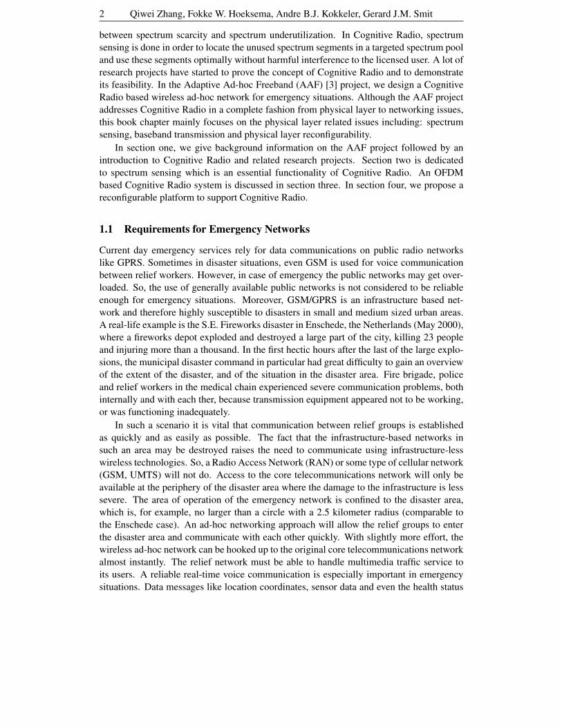
Parameter Value
Frequency Range 380 − 400 MHz
Channel Spacing 25 kHz
TX Power (mobile) 1 − 3 W
Channel Access method TDMA
Modulation method π/4-DQPSK
Channel bit rate 36 kbit/s
Maximum data rate (gross bit rate) 28.8 kbit/s
Net data rate, non-protected: n x 7.2 kbit/s
Low-protected n x 4.8 kbit/s
High-protected n x 2.4 kbit/s
(n = 1, 2, 3 or 4)
Speech coding A-CELP, 4.567 kbit/s
Range Rural ± 14 km
Range Suburban ± 4.5 km
Table 1: Radio parameters of the TETRA System.
of the rescue workers are also needed. Pictures and video can be used for surveillance and
locating objects. To support multimedia services, different constraints on QoS have to be
met. Real-time voice and video are sensitive to delay and jitter while data messages have
high requirements on data loss and error rates. The voice and video provide more or less
predictable network load due to their streaming behavior but data traffic is rather bursty in
nature. In short, the network must be able to handle a wide variety of multimedia signals
and has to deal with large, possibly unpredictable amounts of data. The large amounts of
data require a large amount of radio resources.
There are also public safety networks like C2000 which is based on TETRA (see ta-
ble 1).
One may observe that there are limited data communication facilities available in
C2000. Also this network is infrastructure based (there are fixed base stations) and thus
susceptible to the type of disasters we conceive.
The state-of-the-art systems lack capabilities (e.g. in offered data rates or multimedia
traffic support) and are not disaster proof. The other major drawback of current emergency
networks is their spectrum scarcity [4] because current emergency networks are assigned
with a limited spectrum and fixed bandwith. As we mentioned earlier, the large amounts of
multimedia data in the emergency networks require a large amount of radio resources. One
band can easily get congested due to heavy traffic, which makes it inadequate for emer-
gency use. If several fragmented bands are assigned to emergency use, the interoperability
and the lack of standards will become another problem [5]. Therefore to alleviate this spec-
trum shortage problem, a radio which dynamically accesses free spectrum resources turns
out to be an interesting solution. This approach is called Cognitive Radio according to Mi-
tola [1], who first came up with the concept. He defined Cognitive Radio as a radio that
can change its transmission based on interaction with its environment. This definition can
be very broad, including knowledge of services, user behaviour and spectral usage. The
AAF project focuses on two key elements, i.e. searching for under-utilised spectrum, and

4 Qiwei Zhang, Fokke W. Hoeksema, Andre B.J. Kokkeler, Gerard J.M. Smit
(rapidly) adapting transmission settings accordingly.
The first step in the project is to focus on identification of free resources in the frequency
domain by spectrum sensing. Subsequentially we identify an OFDM-based system which
is theoretically optimal in approaching the Shannon capacity in the segmented spectrum
by sending at different rates and powers over each subcarrier. We believe that the capacity
to nullify individual carriers poses interesting opportunities for cognition, as was also ob-
served in [6]. Cognitive Radio has to operate in different frequency bands, combat various
negative effects of wireless channels and support various multimedia services. Therefore
Cognitive Radio needs physical layer reconfigurability. So, we propose a heterogeneous
reconfigurable platform to enable the evolution from the traditional software defined radio
to Cognitive Radio.
1.2 Cognitive Radio
The idea of Cognitive Radio was first presented by Joseph Mitola III in his paper [7], where
he proposed that Cognitive Radio can enhance the personal wireless service by a radio
knowledge representation language (RKRL). This language represents knowledge of radio
at all aspects from transmission to application scenarios in such a way that automated rea-
soning about the needs of the user is supported. Explained in a simple way, Cognitive Radio
is able to autonomously observe and learn the radio environment, generate plans and even
correct mistakes. A comprehensive conceptual architecture of Cognitive Radio was later
presented in [1], where Cognitive Radio was thought as a final point of the software-defined
radio platform evolution: a fully reconfigurable radio that changes its communication func-
tions depending on network and/or user demands. Mitola’s work covered interesting re-
search subjects in multiple disciplines such as wireless communication, computer science
and cognitive science.
On the other hand, the radio regulatory bodies in various countries found that most of
the radio frequency spectrum was inefficiently utilized. In November 2002, the Federal
Communications Commission (FCC) in the United States released a report [8] aimed at
improving the management of spectrum resources in the US. The report concluded that the
current spectrum scarcity problem is largely due to the strict regulation on spectrum access.
The spectrum measurements conducted by the FCC indicated that only small portions of the
spectrum are heavily used while other frequency bands are either partially used or unoccu-
pied most of the time. So, spectrum utilization can be improved by making it possible for
a secondary user (who doesn’t have the license for spectrum) to access the spectrum which
is not occupied by the licensed user (primary user). This secondary user has the awareness
of the spectrum and adapts its transmission accordingly on a non-interference basis. This
spectrum access and awareness scheme is referred to as Cognitive Radio by the FCC, which
is a narrower definition compared with the original concept brought up by Mitola.
1.3 Projects Related to Cognitive Radio
Since the concept of Cognitive Radio first appeared, research activities have started around
the world. Recently, Cognitive Radio became a very hot topic due to its impact on future
spectrum policy which could fundamentally change the current status of radio communica-
tion. We mention a few research projects related to Cognitive Radio.

Towards Cognitive Radio For Emergency Networks 5
In Berkeley Wireless Research Center (BWRC), a dedicated Cognitive Radio Research
(CRR) project is in progress. A white paper on Cognitive Radio has been produced [9]
earlier and recently they reported a real time Cognitive Radio testbed for physical layer
and link layer experiments [10]. Their motivation is to improve the spectrum utilization by
opportunistic use of the spectrum, which is the same as the FCC’s initiative. They treat the
subject in a complete fashion: from physical layer issues to MAC layer issues and from
analog frontend to computing platform supporting baseband processing. It is interesting to
look into their study on spectrum sensing. From the system perspective, they study some
basic considerations: the link budget of the sensing; the effect of noise on sensing; the
cooperation of sensing nodes. From the signal processing perspective, a comparison study
is made on different sensing techniques. Some hardware considerations related to sensing
are also proposed see [11].
Spectrum pooling [6] is investigated by Jondral from the University of Karlsruhe. The
basic idea is that a secondary user can dynamically access the licensed band by switch-
ing on and off OFDM subcarriers to avoid interference to the licensed user (primary user).
However, the spectrum power leakage problem in the FFT based traditional OFDM systems
could cause potential interference to the licensed system. They also observed this in [12],
where two counter measures are proposed: spectrum shaping and switching off the carri-
ers adjacent to the licensed user (primary user). There are other challenges for spectrum
pooling like detection of spectrum access and synchronization, see [6].
The Cognitive Radio project [13] at Virginia Tech. does not specifically aim to im-
prove spectrum utilization. This project is based on the observation that Cognitive Radio
distinguishes itself by awareness and learning. In [14], a genetic algorithm based cognitive
engine is proposed to learn its environment and respond with an optimal adaption. This
approach to Cognitive Radio is more or less similar to the original concept of Mitola.
The European Union 6th framework End-to-End Reconfigurability (E2R) [15] project
brings together major European players in the domain of reconfigurability, software de-
fined radio and cognitive radio. The key objective of the E2R project is to devise, develop,
trial the architectural design of reconfigurable devices and supporting system functions for
users, application and service providers, operators, and regulators in the context of het-
erogeneous systems. Although the project does not specifically address Cognitive Radio,
dynamic spectrum allocation and evolution from software defined radio to Cognitive Radio
has been envisioned.
In parallel with the ongoing research projects around the world, international standard-
ization organizations also have proposals to improve the spectrum utilization. An example
is IEEE 802.22 [16], which is a new standard for a cognitive point-to-point (P2P) air inter-
face for spectrum sharing with television bands. Television channels are very suitable for
cognitive radio because they have a relatively unique spectrum signature that is easy for a
cognitive radio to identify. The signals are also rigidly assigned to 6-MHz-wide channels
with fixed center frequencies.
In the scope of our AAF project, we focus on the spectrum awareness and access. The
objective is to demonstrate a Cognitive Radio system for emergency networks. Each radio
node works in an ad-hoc based network, the node adopts the AAF protocol stack which
is consistent with the five-layer protocol reference model (physical layer, data link layer,
network layer, transport layer and application layer). The physical layer is the heart of our

6 Qiwei Zhang, Fokke W. Hoeksema, Andre B.J. Kokkeler, Gerard J.M. Smit
study where the free spectrum is discovered. Whenever the free spectrum is found, the AAF
system will create an infrastructure using this spectrum.
2 Spectrum Sensing
In this section an architecture of a generic sensing system is described which consists of a
spectral analysis system and a decision system. As an example, we present a sensing system
that uses energy detection in the frequency range between 400−500 MHz. For disaster relief
networking this range is interesting because of propagation conditions, power requirements
and antenna dimensions.
A brief analysis into the gains to be expected by collaborative scanning, a form of
distributed detection, completes this section.
2.1 Sensing System Architecture
In Figure 1 a functional architecture of a sensing system is presented. Basically the system
consists of two parts: a spectral analysis system and a decision system. An option for
the spectral analysis system is to use energy detection (power detection). In this case the
scanning system works on any signal, however, without using all available knowledge of
signal properties of the primary user. Another option is to use feature establishment - one
identifies well known (deterministic) signal features of the primary user’s signal like carrier
waveforms or pilot tones. As, for instance in broadcast situations, the primary user wants
to be heard, it is expected that especially in bad SNR conditions feature establishment
may outperform energy detection [17]. In this paper we focus on energy detection, as it
is applicable to any primary user signal and possibly less energy consuming than feature
detection.
Power / Feature
Measurement
Local
Decision
Global
Decision
FOI TX
FOI RX
Channel
Selection
Spectral Analysis System Decision System
to BB processing
FOI: Frequency Occupancy InformationBB: Base Band
Figure 1: Functional Architecture of the sensing system.
A single scanning node needs to decide whether or not the band under consideration
is empty or not, hence it takes a local decision. The quality of this decision (in terms
of detection probability Pd and False Acceptance Rate (FAR)) may be hampered by two
issues:

Towards Cognitive Radio For Emergency Networks 7
Multipath fading Signals that travel different signal paths may or may not add coherently
at the receiver. As a result, small changes in location (relative to the wavelength λ)
impact detection quality.
Shadowing An individual sensing node may be blocked by an obstacle and may therefore
not be able to detect the primary user. Shadowing may occur over an area of 5 −500 m, depending on the size of the object.
To overcome these problems, a collaborative scanning system can be used. In such
a system Frequency Occupancy Information (FOI) is gathered by all individual scanning
nodes and disseminated to the nodes participating in the secondary-user network using a
special signalling channel for this purpose. The properties of this FOI dissemination chan-
nel (like its bandwidth, SNR, data rate, MAC protocol and delay), the independence of
measurements and the number of nodes involved in the scheme all determine the gains in
detection quality to be expected over locally-made-only decisions.
Leaving aside feature detection, the channel selection and power measurement part to-
gether form a spectrum analyser. Below we focus on alternative architectures for such a
system.
2.2 Architectures of the Spectral Analysis System
We distinguish three architectures for the spectrum analysis part of a power-based sensing
system: a scan-based architecture, a real-time FFT based architecture and an FFT-based
architecture.
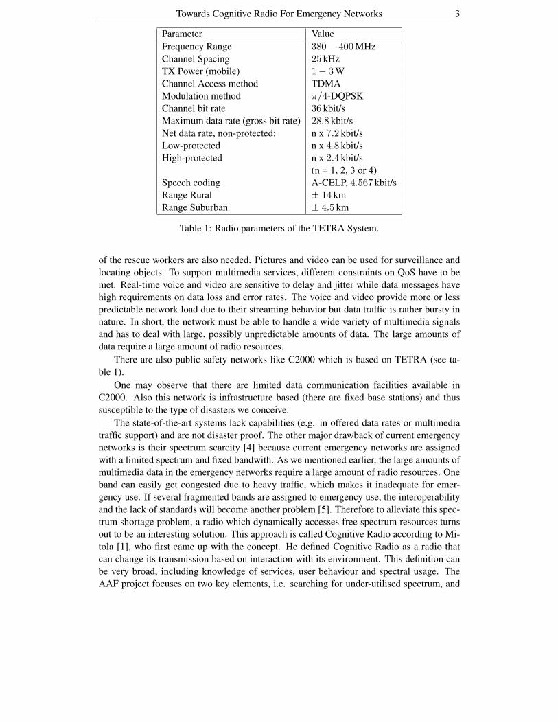
2.2.1 Scan-based Architecture
In Figure 2a, a scan-based architecture is presented. After a broad lowpass filter, a mixer
driven by a local oscillator (LO) downconverts the signal to some intermediate frequency
(IF). Subsequently the signal is anti-alias filtered, mixer products are removed and analog-
to-digital conversion (ADC) is performed. In the digital realm a sample-and-hold type of
filter is used and subsequently the energy in a particular frequency bin is computed. Instead
of measuring frequency bins in parallel, they are measured sequentially, by changing the
frequency of the LO and sweeping over the required frequency span (FS).
One critical design issue (especially for handheld nodes) is the power consumption
of the AD converter. In order to compare the performance of AD converters a Figure of
Merit (FoM) can be used that takes into account the converter’s power dissipation P [W],
its resolution (specified in Effective Number of Bits (ENOB)) and its sampling rate fs
[Hz], [18], [19]. This FoM is given by
FoM =P
2ENOB . fs
[ pJ / conversion-step ]. (1)
in which a FoM of approximately 2 pJ / conversion-step is valid for today’s ADCs. As
dynamic ranges of as large as 80 dB can be observed for the 400 MHz-500 MHz frequency
range ( [20], [21, pp.77-84]) approximately 80 / 6 = 14 bits ENOB are needed (we apply
8 Qiwei Zhang, Fokke W. Hoeksema, Andre B.J. Kokkeler, Gerard J.M. Smit
the well-known 6 dB/bit rule for ADCs), which severely limits the possible bandwidth that
can be converted (say, to around fs/2 = 1 − 10 MHz, so power P = 66 − 655 mW).
However, the main disadvantage of the sweeping approach is the huge loss of time
resolution. First, it takes time for the filters to settle, which is inversely related to the
resolution bandwidth (RBW). So the sweep frequency has to ‘dwell’ a certain amount of
time in every frequency band. Also, the completion of one sweep takes an amount of time
proportional to FS/RBW , so the sweep time is equal to
ST = kFS
RBW 2 (2)
in which k is a factor that depends on the filter type with typical values between 2 and
3, [22].
In Figure 2b the time-frequency diagram of the scan based approach is shown. In this
figure the primary parameters involved in the scan-based method are indicated. The scan-
ning starts one time ts on frequency fL. The scanning ends on te on frequency fH . The
complete scan time is ST, and the frequency span is FS. The Inter-bin frequency (IBF) is the
distance between two adjacent frequency bins. The Inter-bin time (IBT) is the time it takes
to complete a power measurement in a single time-frequency bin. The frequency bins are
described by two parameters: The resolution bandwidth (RBW) and the dwell time (Td).
The gray bins are the time-frequency points that are ‘seen’ by the spectrum analyser.
The bins that are not on the gray diagonal are just missed. Depending on the usage pattern
of the primary user, this may or may not be a problem. In case of stable broadcast bands it
seems less of a problem than in data-communication bands. In the example the number of
bins is #points=8.
Attenuator Lowpass Filter Mixer Filter FilterIF Amplifier
ADC
Sample
Clock
Processor
Span Control
Centre
Frequency
Control
Local
Oscillator
(a) Architecture.
t
f
0
IBF
IBTts te
fL
fH
FS
ST
RBW
Td
Scan-based Spectrum Analyser time-frequency trace
Sojourn bin
Power
sample
Sojourn binSojourn bin
Power
sample
Time or freq.
sample-
instance
at which a
measurement
is available
(b) Time-Frequency diagram.
Figure 2: Scan-based approach.
2.2.2 Real-time FFT based Architecture
Another approach is to calculate the spectrum with a discrete Fourier transform (DFT) from
time domain measurements instead of measuring it directly.
Since we want to perform the Fourier transform digitally we first have to convert the
RF signal to baseband using a quadrature mixer, apply an anti aliasing filter, remove mixing
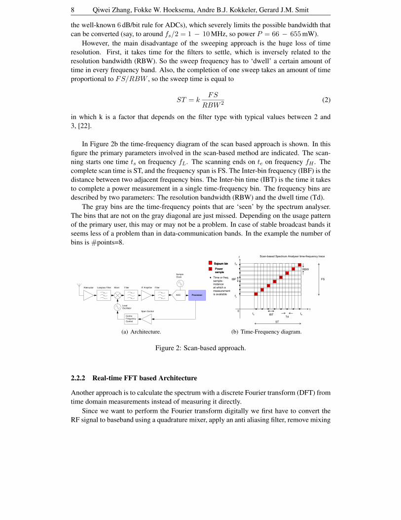
Towards Cognitive Radio For Emergency Networks 9
products and apply analog-to-digital conversion. A digital signal u[n] has a discrete Fourier
transform U [k] defined as:
U [k] =N−1∑
n=0
u[n] e−j 2π
Nk n with k = 0, . . . , N − 1 (3)
The conversion from time domain to frequency domain can be done with the very effi-
cient FFT (Fast Fourier Transform) algorithm which takes only about N log(N) multiplica-
tions instead of the N2 multiplications for a general DFT. In Figure 3a, the architecture of
the FFT based method is shown. The front end is tuned on a fixed frequency. The channel
select filter is replaced by a much wider filter that passes the whole frequency span. The
selection of the frequency bins is now done by the FFT which processes all channels in
parallel.
Attenuator Lowpass Filter
Quadrature
Mixer
Filters
ADC
Sample
Clock
Processor
Local
Oscillator
ADC
900
The FFT is computed in
the processor
(a) Architecture.
1 sojourn bin
(& its samples):
Power
sample
t
f
0
IBF
Tts te
fL
fH
FS
ST = Tac
RBW
Tac
Real-Time FFT based Spectrum Analyser time-frequency trace
ST = Tac
Td = Tac
IBT = Tac
FS = fs
RBW = ∆f
IBF = ∆f
…
…
Td = TacIBT = Tac
…
…
Example: N=8
(b) Time-Frequency diagram.
Figure 3: FFT-based approach.
The primary parameters involved in the FFT-based approach are given in 3b. If we
compare this figure with Figure 2b we see some important differences. First we see that now
all bins are covered instead of just one diagonal. So there are no points in the time-frequency
plane that are missed. We also see that the measurement results for all frequency bins
become available at the same time, after the scan time ST, which is equal to the acquisition
time if we neglect the processing time (Tac = N T , with T the sampling time). The
frequency span is equal to the sample frequency FS = fs = 1/T .
The real-time FFT based method has drawbacks too. The major disadvantage of the
FFT method is that two ADCs is needed, which cause even more power-related problems
as was the case for the scan-based architecture. For instance, an FS of 100 MHz cannot
be accommodated. However, in the UHF/VHF region bandwidths of 1 − 10 MHz seem
feasible.
2.2.3 Scanning-FFT based Architecture
A scan-based architecture is more energy-efficient compared to a real-time FFT based one,
but considered too slow for our purposes. The real-time FFT based architecture is fast but
too power intensive for a large frequency span, so the natural way to proceed is to combine
both methods. One chooses a feasible FFT size (determined by the power requirements
of the ADC) with a frequency span that is (thus) a fraction of the total span required. We

10 Qiwei Zhang, Fokke W. Hoeksema, Andre B.J. Kokkeler, Gerard J.M. Smit
then can use the FFT multiple times and adjust the centre frequency of the front end each
time so that the whole span is covered. In Figure 4 the resulting architecture and the time-
frequency diagram of this configuration are given (in the example, F=2 tuning steps of the
LO are needed).
Attenuator Lowpass Filter
Quadrature
Mixer
Filters
ADC
Sample
Clock
Processor
Centre
Frequency
Control
Local
Oscillator
ADC
900
The FFT is computed in
the processor
Span Control
(a) Architecture.
t
f
0
IBF
Tts te
fL
fH
FS
ST
RBW
Tac
Scanning-FFT based Spectrum Analyser time-frequency trace
F FFTs per FS
ST = F . Tac
FS = F . fs
1 sojourn bin
(& its samples):
Power
sample
…
…
Example: N=4, F=2
(b) Time-Frequency diagram.
Figure 4: Scanning-FFT based approach.
To provide some quantitative insight we provide an example. Assume we require a total
frequency span of FS = 100 MHz with a resolution of RBW = 10 kHz, so 10000 bins.
If we want to process this with a radix-2 FFT we need to sample and compute an 16384
points FFT every Tac = 100µs (the first power of two larger than 10000). This makes up
a substantial computational load.
If we use a scan-based architecture, according to equation (2) with k=2, it will take the
sweep 2 100 . 106
(10 . 103)2= 2 s to complete, which may be too long if we want to detect within a
MAC frame duration (in the order of milliseconds).
If we use a scanning-FFT based architecture, we can partition the total span in 20 blocks
of 5 MHz, which may be processed by calculating 512 points every 100 µs. And since the
bandwidth is reduced by a factor 20, the sampling rate and thus the power consumption is
also reduced by the same factor (see (1)).
Another benefit of a scanning-FFT based architecture is that the LO can interplay inde-
pendently with a hopping baseband processing system, as was suggested in [23].
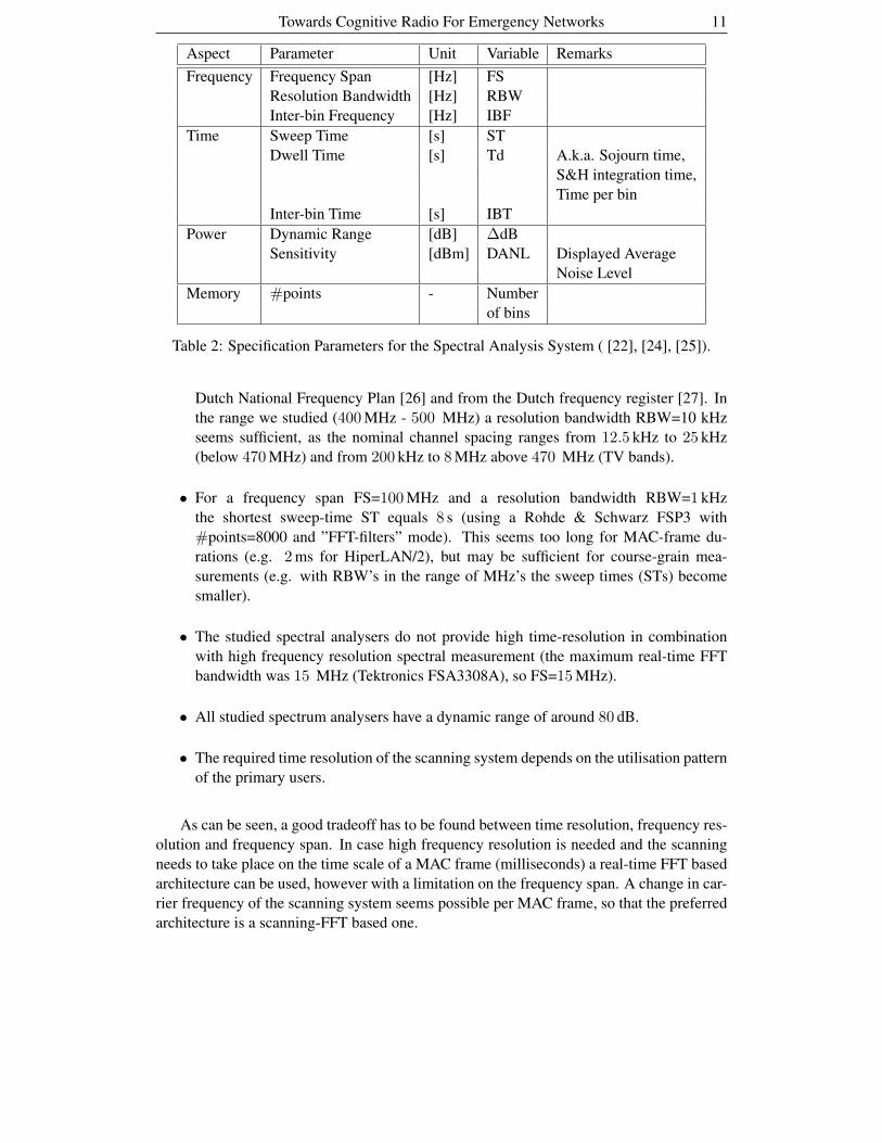
2.3 Specification Parameters for the Spectral Analysis System
The spectral analysis system can be described by the specification parameters of a spectrum
analyzer as given in table 2. The meaning of the parameters is illustrated in figures 2b, 3b
and 4b. Note that the parameters are not independent of one another and, moreover, the
dependency depends on the chosen scan-system architecture (see [22], [24] and [25]).
As an example, consider a frequency range of interest from 400 MHz to 500 MHz. In
order to see what current-day capabilities of energy-based sensing systems are, we investi-
gate the capabilities of existing commercially available spectrum analysers (Agilent 4407B,
Rohde & Schwarz FSP3 and Tektronics FSA3308A). Below, we present some parameter-
values of these systems.
• The required frequency resolution of the scanning system can be taken from the
Towards Cognitive Radio For Emergency Networks 11
Aspect Parameter Unit Variable Remarks
Frequency Frequency Span [Hz] FS
Resolution Bandwidth [Hz] RBW
Inter-bin Frequency [Hz] IBF
Time Sweep Time [s] ST
Dwell Time [s] Td A.k.a. Sojourn time,
S&H integration time,
Time per bin
Inter-bin Time [s] IBT
Power Dynamic Range [dB] ∆dB
Sensitivity [dBm] DANL Displayed Average
Noise Level
Memory #points - Number
of bins
Table 2: Specification Parameters for the Spectral Analysis System ( [22], [24], [25]).
Dutch National Frequency Plan [26] and from the Dutch frequency register [27]. In
the range we studied (400 MHz - 500 MHz) a resolution bandwidth RBW=10 kHz
seems sufficient, as the nominal channel spacing ranges from 12.5 kHz to 25 kHz
(below 470 MHz) and from 200 kHz to 8 MHz above 470 MHz (TV bands).
• For a frequency span FS=100 MHz and a resolution bandwidth RBW=1 kHz
the shortest sweep-time ST equals 8 s (using a Rohde & Schwarz FSP3 with
#points=8000 and ”FFT-filters” mode). This seems too long for MAC-frame du-
rations (e.g. 2 ms for HiperLAN/2), but may be sufficient for course-grain mea-
surements (e.g. with RBW’s in the range of MHz’s the sweep times (STs) become
smaller).
• The studied spectral analysers do not provide high time-resolution in combination
with high frequency resolution spectral measurement (the maximum real-time FFT
bandwidth was 15 MHz (Tektronics FSA3308A), so FS=15 MHz).
• All studied spectrum analysers have a dynamic range of around 80 dB.
• The required time resolution of the scanning system depends on the utilisation pattern
of the primary users.
As can be seen, a good tradeoff has to be found between time resolution, frequency res-
olution and frequency span. In case high frequency resolution is needed and the scanning
needs to take place on the time scale of a MAC frame (milliseconds) a real-time FFT based
architecture can be used, however with a limitation on the frequency span. A change in car-
rier frequency of the scanning system seems possible per MAC frame, so that the preferred
architecture is a scanning-FFT based one.

12 Qiwei Zhang, Fokke W. Hoeksema, Andre B.J. Kokkeler, Gerard J.M. Smit
2.4 Collaborative Scanning: Distributed Detection
In this secction we propose a decision system for the detection of a primary user signal.
Suppose the decision system (see Figure 1) takes a local hard-decision (a yes/no one) on an
energy-based measure. So, for the k-th frequency bin
Ek = |U [k]|2 (4)
is computed with U [k] as in (3). Assume U [k] = X[k] + W [k] in which {X[k]} is the
(complex-valued) primary user signal in the k-th frequency bin (which can be anything,
with unknown distribution) and {W [k]} is assumed to be (complex-valued) white Gaus-
sian noise, independent of the primary user’s signal. The expected value of the signal is
E[|U [k]|2] = E[|X[k]|2] + E[|W [k]|2]. Now, we formulate two hypotheses Hi:
H0 : no primary user signal is present, so |U [k]|2 = |W [k]|2, and
H1 : a primary user signal is present.
Subsequently we define a decision rule D:
Dk = 0 in case Ek < θ and Dk = 1 in case Ek > θ
in which Dk is the decision made by the local decision system for the k-th frequency bin
and θ is the detection threshold.
� � � � � ��
���
���
���
���
�
I(N_+��q�
q
I(N_+��q�
(a) Conditional pdfs fEk | H0and fEk | H1
.
��� ��� ��� ��� �
���
���
���
���
�
)$5
q� ��q� ��q� ��q� ��
q� ��
q� ��
3G
(b) ROC: Pd as a function of FAR.
Figure 5: Detection quality of a single node.
The quality of the detection can be expressed in two conditional probabilities, the detec-
tion probability Pd and the false alarm rate FAR. The probability of detecting a primary-
user signal is given by Pd , Pr[Dk = 1 |H1], the probability of detecting noise instead of
a primary-user signal is FAR , Pr[Dk = 1 |H0]. In case the probability density functions
(pdfs) of Ek under both hypotheses are available, so fEk |H1(x) and fEk |H0
(x) are known,
the detection probability and false alarm rate can be computed as

Towards Cognitive Radio For Emergency Networks 13
Pd =∫ ∞θ
fEk |H1(x) dx
(5)
FAR =∫ ∞θ
fEk |H0(x) dx.
A graph of Pd versus FAR is called a Receiver Operating Curve (ROC), see [28].
An example for the pdfs in Figure 5a is given in Figure 5b. Observe that it is in fact the
choice of the threshold value θ that determines a position on the curve in the graph. What
a good choice of Pd and FAR is, is determined by other criteria like the cost of causing
interference to a primary user (rudeness), or the cost of finding too little unoccupied
spectrum (weakness).
Can the detection quality for the k-th frequency bin be improved by combining the hard
decisions of N nodes for this bin?
We assume that a particular sensing node receives the decisions of the N−1 other nodes
through the FOI channel. The question is now how to combine these N local decisions into
a global one (aiming at better quality). A possible fusion rule is a rule which decides H1 if
any of the N received local decisions is 1 (the 1-out-of-N rule or OR-rule). For this fusion
rule the detection probability P(N)d is [29]:
P(N)d = 1 − (1 − Pd)
N (6)
and the FAR(N) is
FAR(N) = 1 − (1 − FAR)N . (7)
In Figure 6 the effects of this rule and the number of collaborative nodes are illustrated.
By increasing N it can be seen that the ROC curves creep into the upper left corner, signi-
fying improved detection quality.
��� ��� ��� ��� �
���
���
���
���
�
3G
)$5
1��
����
Figure 6: ROC for collaborative scanning (N nodes).

14 Qiwei Zhang, Fokke W. Hoeksema, Andre B.J. Kokkeler, Gerard J.M. Smit
Observe that in this analysis we assumed that all nodes independently “see the same
thing (primary user’s frequency occupancy)”. Apart from the fusion rule shown here, other
rules may be applied that result in a different detection quality for the collaborating nodes.
In case nodes are in disagreement (e.g. because of fading or shading they do not “see the
same thing”) another analysis is necessary and another fusion rule may outperform the one
sketched here.
The approach assumes a more or less errorless instantaneous availability of FOI in-
formation for the global decision function (Figure 1). As such the values found by this
method of analysis have to be interpreted as a benchmark for practical collaborative sens-
ing schemes in which (imperfect) FOI dissemination channels are used.
3 OFDM Based Cognitive Radio Baseband System
In this section we present adaptive OFDM based schemes for Cognitive Radio. We will first
discuss adaptive bit loading and adaptive power loading. Second, we will discuss the basic
OFDM baseband processing functions in an OFDM receiver.
3.1 Adaptive bit loading and adaptive power loading
The basic idea of Orthogonal Frequency Division Multiplexing (OFDM) is to transmit high
data rate information by dividing the data into several parallel bit streams where these bit
streams are modulated by orthogonal frequencies. The benefit of OFDM is that the high
data rate of the whole system is transformed into relatively low data rate streams on each
subcarrier which is more robust to inter symbol interference (ISI) caused by multipath delay
spread. In the hardware design, it is expected that an OFDM radio is also easy to integrate
with spectrum sensing because both of them use FFT cores. The system robustness and
hardware resource sharing make OFDM a good choice for Cognitive Radio baseband sys-
tems. More importantly, an OFDM system can optimally approach the Shannon capacity in
the segmented spectrum by adaptive resource allocation on each subcarrier, which includes
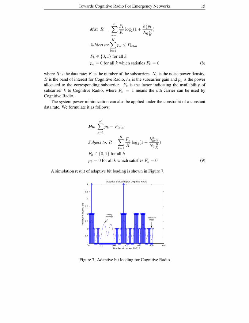
adaptive bit loading and adaptive power loading [30]. In an OFDM based Cognitive Radio
system, information bits are loaded as different modulation types onto each available sub-
carrier depending on the subcarrier’s signal to noise ratio while the subcarriers currently not
available to Cognitive Radio are switched off. Two optimization methods for the adaptive
resource allocation can be used for Cognitive Radio: using the power constraint or using
the data-rate constraint.
We could maximize the data rate of the system under a certain power constraint. It is
formulated as follows:
Towards Cognitive Radio For Emergency Networks 15
Max R =K∑
k=1
Fk
Klog2(1 +
h2kpk
N0BK
)
Subject to:
K∑
k=1
pk ≤ Ptotal
Fk ∈ {0, 1} for all k
pk = 0 for all k which satisfies Fk = 0 (8)
where R is the data rate; K is the number of the subcarriers. N0 is the noise power density,
B is the band of interest for Cognitive Radio, hk is the subcarrier gain and pk is the power
allocated to the corresponding subcarrier. Fk is the factor indicating the availability of
subcarrier k to Cognitive Radio, where Fk = 1 means the kth carrier can be used by
Cognitive Radio.
The system power minimization can also be applied under the constraint of a constant
data rate. We formulate it as follows:
Min
K∑
k=1
pk = Ptotal
Subject to: R =K∑
k=1
Fk
Klog2(1 +
h2kpk
N0BK
)
Fk ∈ {0, 1} for all k
pk = 0 for all k which satisfies Fk = 0 (9)
A simulation result of adaptive bit loading is shown in Figure 7.
0 100 200 300 400 500 6000
0.5
1
1.5
2
2.5
3
3.5
4
Num
ber
of lo
aded
bits
Number of carriers N=512
Adaptive Bit loading for Cognitive Radio
Fadingenvelope Spectrum
mask
Figure 7: Adaptive bit loading for Cognitive Radio
16 Qiwei Zhang, Fokke W. Hoeksema, Andre B.J. Kokkeler, Gerard J.M. Smit
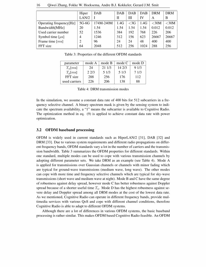
Hiper DAB DAB DAB DAB DRM DRM
LAN/2 I II III IV A B
Operating frequency[Hz] 5G-6G 174M-240M 1.4G <3G 1.4G <30M <30M
Bandwidth[MHz] 20 1.54 1.54 1.54 1.54 0.012 0.012
Used carrier number 52 1536 384 192 768 226 206
Symbol time [µs] 4 1246 312 156 623 26667 26667
Frame time [ms] 2 96 24 24 48 400 400
FFT size 64 2048 512 256 1024 288 256
Table 3: Properties of the different OFDM standards
parameter mode A mode B mode C mode D
Tu[ms] 24 21 1/3 14 2/3 9 1/3
Tg[ms] 2 2/3 5 1/3 5 1/3 7 1/3
FFT size 288 256 176 112
used carriers 226 206 138 88
Table 4: DRM transmission modes
In the simulation, we assume a constant data rate of 400 bits for 512 subcarriers in a fre-
quency selective channel. A binary spectrum mask is given by the sensing system to indi-
cate the spectrum availability, a “1” means the subcarrier is available to Cognitive Radio.
The optimization method in eq. (9) is applied to achieve constant data rate with power
optimization.
3.2 OFDM baseband processing
OFDM is widely used in current standards such as HiperLAN/2 [31], DAB [32] and
DRM [33]. Due to various system requirements and different radio propagations on differ-
ent frequency bands, OFDM standards vary a lot in the number of carriers and the transmis-
sion bandwidth. Table 3 summarizes the OFDM properties for different standards. Within
one standard, multiple modes can be used to cope with various transmission channels by
adopting different parameter sets. We take DRM as an example (see Table 4). Mode A
is applied for transmissions over Gaussian channels or channels with minor fading which
are typical for ground-wave transmissions (medium wave, long wave). The other modes
can cope with more time and frequency selective channels which are typical for sky-wave
transmissions (short wave and medium wave at night). Mode B and C have the same degree
of robustness against delay spread, however mode C has better robustness against Doppler
spread because of a shorter useful time Tu. Mode D has the highest robustness against se-
vere delay and Doppler spread among all DRM modes at the cost of the lowest data rate.
As we mentioned, Cognitive Radio can operate in different frequency bands, provide mul-
timedia services with various QoS and cope with different channel conditions, therefore
Cognitive Radio is able to adapt to different OFDM systems.
Although there are a lot of differences in various OFDM systems, the basic baseband
processing is rather similar. This makes OFDM based Cognitive Radio feasible. An OFDM
Towards Cognitive Radio For Emergency Networks 17
baseband receiver generally consists of the following basic tasks (Figure 8):
• Packet/frame detection and synchronization is used to determine the starting point
of an OFDM frame. This is usually achieved by correlating the received signal with
known preambles. We also refer to this frame synchronization as coarse synchroniza-
tion in contrast with the fine synchronization of the OFDM symbols.
• Frequency offset estimation and correction are done to remove the frequency off-
set which destroys the frequency orthogonality of subcarriers. Frequency offset es-
timation is done on the frame basis in the preamble section (see Figure 8) before
data symbols. A frequency correction coefficient determined by the frequency offset
estimation is multiplied by each OFDM data symbol.
• Channel estimation and equalization are used to correct the frequency selective
fading. Due to the robustness of OFDM to frequency selective fading, less complex
frequency domain equalization techniques can be used.
• Guard time removal is done after the fine synchronization of OFDM symbols.
• FFT is the basic component of all OFDM systems which transforms the signal into
the frequency domain.
• Phase offset tracking and correction correct the frequency offset residual error by
using the pilots in each OFDM symbol.
• De-map transforms the complex numbers to a bitstream according to their modula-
tion types. Different modulation types can be loaded on each subcarrier by applying
adaptive bit-loading as we have mentioned.
• De-interleaving is the opposite task of data interleaving. The idea of data interleav-
ing is that the original data is re-arranged at a transmitter in order to reduce burst
errors on a receiver. De-interleaving is the inverse operation of interleaving.
• Channel decoding exists in all communication systems not only in OFDM systems.
However, OFDM is almost always used in conjunction with channel coding to create
coded OFDM (COFDM). A Viterbi code is commonly used, but other channel codes
such as turbo code or a LDPC code can also be applied. The code rate can be adaptive
to provide different degrees of error protection.
For simplicity we only mentioned the tasks performed by the receiver. The transmitter
basically does the inverse operations which are less complex. The aforementioned func-
tional blocks can be found in all OFDM systems, but different standards may use different
algorithms for each functional block. This means the communication system can select
an algorithm to perform each function depending on the requirements of the system. For
example, different channel encoders/decoders (codecs) can be applied to achieve different
QoS requirements. We refer to this adaptivity as algorithm-selection level adaptivity [34].
For a specific algorithm, there are also opportunities for adaptivity by changing parameters
of the algorithm. For example the size of FFT and the code rate of Viterbi codec can be

18 Qiwei Zhang, Fokke W. Hoeksema, Andre B.J. Kokkeler, Gerard J.M. Smit
Frame detection
and synchronization
Guard time
removalFFT
Channel
equalization
Phase offset
correction
De-map
Frequency
offset
estimation
Tim
eF
requency
Frequency
Offset
correction
Channel
estimation
De-interleavingChannel
decoding
To source
decoding
Frame detection
and synchronization
Guard time
removalFFT
Channel
equalization
Phase offset
correction
De-map
Frequency
offset
estimation
Tim
eF
requency
Frequency
Offset
correction
Channel
estimation
De-interleavingChannel
decoding
To source
decoding
OFDM
Frame
OFDM frame:
Frame preamble OFDM symbols
Guard time Useful data
Frame preamble OFDM symbols
Guard time Useful dataOFDM symbol:
Figure 8: Basic OFDM processing tasks
tuned by different standards or modes. We refer to this adaptivity as algorithm-parameter
level adaptivity. The next question is how to achieve the adaptivity for different OFDM
systems. A fully reconfigurable hardware platform will be an ideal solution.
4 Heterogeneous Reconfigurable Platform
As already foreseen by Mitola [1], a Cognitive Radio is the final point of software-defined
radio platform evolution: a fully reconfigurable radio that changes its communication func-
tions depending on network and/or user demands. His definition on reconfigurability is very
broad and we therefore focus on a reconfigurable hardware platform which supports Cog-
nitive Radio. In this section, we present a heterogeneous reconfigurable hardware platform
for Cognitive Radio.
4.1 A Heterogeneous Reconfigurable System-on-Chip Architecture
With the evolution of semiconductor technology, more and more transistors can be inte-
grated on a single chip which makes it possible to build large systems, on a chip level rather
than on a board level. This approach is called System-on-Chip (SoC). The reconfigurable
platform we propose for Cognitive Radio is a heterogeneous reconfigurable SoC architec-
ture shown in Figure 9.
This SoC is a heterogeneous tiled architecture, where tiles can be various processing
elements including General Purpose Processors (GPPs), Field Programmable Gate Arrays
(FPGAs), Application Specific Integrated Circuits (ASICs) and Domain Specific Reconfig-
urable Hardware (DSRH) modules. The tiles in the SoC are interconnected by a Network-
on- Chip (NoC). Both the SoC and NoC can be dynamically reconfigurable, which means
that the programs (running on the reconfigurable processing elements) as well as the com-
munication links between the processing elements are configured at run-time. Different pro-

Towards Cognitive Radio For Emergency Networks 19
DSRHDSRH DSP FPGA
DSP ASIC
ASIC
GPP ASIC DSP
GPP
DSRH
DSP
ASIC
GPP
GPP
DSRH
DSRH
FPGADSRH
R
R
R
R
R
R
R
R
R
R
R
R
R
R
R
R
R
R
R
R
Figure 9: An example of a heterogeneous System on Chip (SoC). DSRH = Domain Specific
Reconfigurable Hardware
cessing elements are used for different purposes. The general purpose processors are fully
programmable to perform different computational tasks, but they are not energy-efficient.
The dedicated ASICs are optimized for power and cost. However, they can not be recon-
figured to adapt to new applications. FPGAs which are reconfigurable by nature, are good
at performing bit-level operations but not that efficient for word level DSP operations. The
Domain Specific Reconfigurable Hardware (DSRH) is a relatively new type of processing
element, where the configurable hardware is tailored towards a specific application domain.
The Montium [35] tile processor (see Figure 10) developed at the University of Twente, and
recently commercialised by Recore Systems, is an example of DSRH. It targets the digi-
tal signal processing (DSP) algorithm domain, which is the heart of the wireless baseband
processing. In our previous work [36] [37] [38], several DSP algorithms used in wireless
communication have been mapped onto the Montium architecture. The implementation re-
sults show that the Montium architecture is flexible enough to adapt to different algorithms
with good energy-efficiency. In a broader sense, working intelligently in an energy-efficient
way is an important feature of Cognitive Radio. For Cognitive Radio devices working in
the emergency network, energy-efficiency is really a crucial issue because the battery life
of radio devices can be a limitation for successful operations. Therefore the reconfigurable
platform we propose not only targets flexibility but also energy-efficiency. In the next sec-
tion, we will introduce the key element of this platform, the Montium tile processor.
4.2 The Montium Tile Processor
The Montium is an example of DSRH which targets the 16-bit digital signal processing
(DSP) algorithm domain. At first glance the Montium architecture bears a resemblance to
a Very Long Instruction Word (VLIW) processor. However, the control structure of the
Montium is very different. For (energy-) efficiency it is imperative to minimize the control
overhead. This can be accomplished by statically scheduling instructions and using instruc-
tion decoders. The lower part of Figure 10 shows the Communication and Configuration
20 Qiwei Zhang, Fokke W. Hoeksema, Andre B.J. Kokkeler, Gerard J.M. Smit
PP PP PP PPPP
Interconnect
Communication and Configuration Unit
ALU1 ALU2 ALU4 ALU5
Sequencer
Memory
decoder
Inter-
connect
decoder
Register
decoder
ALU
decoder
M01 M02 M03 M04 M05 M06 M07 M08 M09 M10
PPA
Tile
Pro
cesso
r
ALU3
PP PP PP PPPP
Interconnect
Communication and Configuration Unit
ALU1 ALU2 ALU4 ALU5
Sequencer
Memory
decoder
Inter-
connect
decoder
Register
decoder
ALU
decoder
M01 M02 M03 M04 M05 M06 M07 M08 M09 M10
PPA
Tile
Pro
cesso
r
ALU3
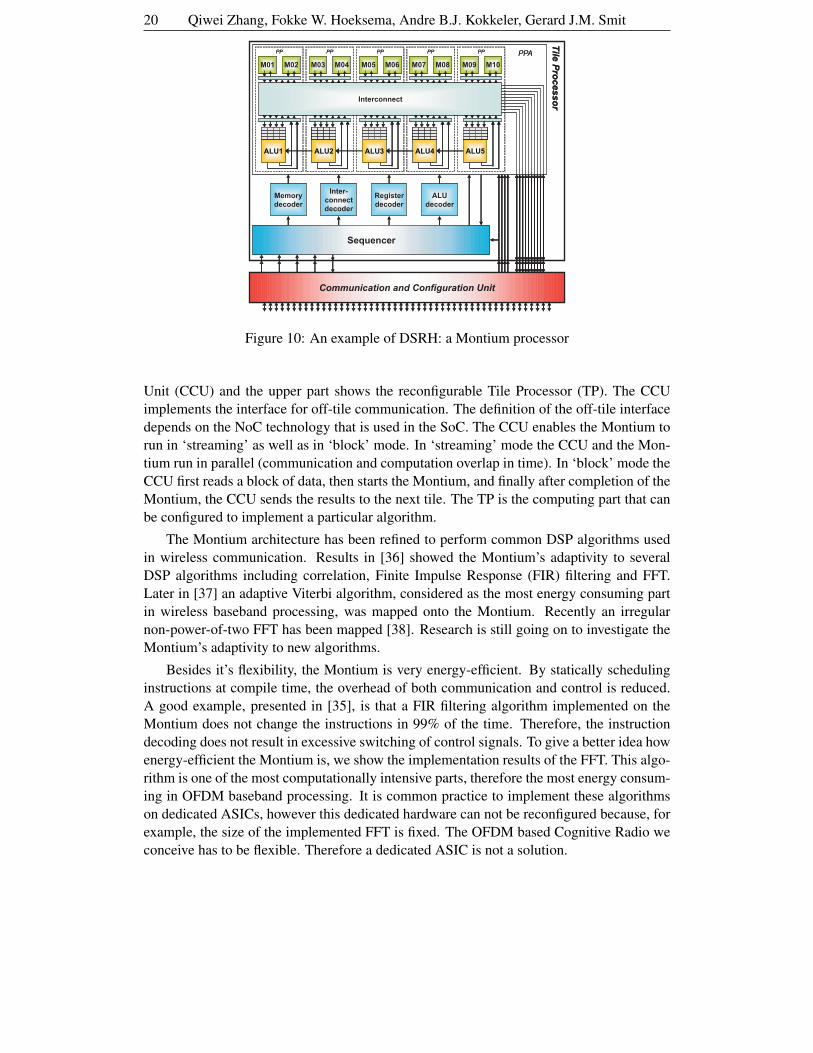
Figure 10: An example of DSRH: a Montium processor
Unit (CCU) and the upper part shows the reconfigurable Tile Processor (TP). The CCU
implements the interface for off-tile communication. The definition of the off-tile interface
depends on the NoC technology that is used in the SoC. The CCU enables the Montium to
run in ‘streaming’ as well as in ‘block’ mode. In ‘streaming’ mode the CCU and the Mon-
tium run in parallel (communication and computation overlap in time). In ‘block’ mode the
CCU first reads a block of data, then starts the Montium, and finally after completion of the
Montium, the CCU sends the results to the next tile. The TP is the computing part that can
be configured to implement a particular algorithm.
The Montium architecture has been refined to perform common DSP algorithms used
in wireless communication. Results in [36] showed the Montium’s adaptivity to several
DSP algorithms including correlation, Finite Impulse Response (FIR) filtering and FFT.
Later in [37] an adaptive Viterbi algorithm, considered as the most energy consuming part
in wireless baseband processing, was mapped onto the Montium. Recently an irregular
non-power-of-two FFT has been mapped [38]. Research is still going on to investigate the
Montium’s adaptivity to new algorithms.
Besides it’s flexibility, the Montium is very energy-efficient. By statically scheduling
instructions at compile time, the overhead of both communication and control is reduced.
A good example, presented in [35], is that a FIR filtering algorithm implemented on the
Montium does not change the instructions in 99% of the time. Therefore, the instruction
decoding does not result in excessive switching of control signals. To give a better idea how
energy-efficient the Montium is, we show the implementation results of the FFT. This algo-
rithm is one of the most computationally intensive parts, therefore the most energy consum-
ing in OFDM baseband processing. It is common practice to implement these algorithms
on dedicated ASICs, however this dedicated hardware can not be reconfigured because, for
example, the size of the implemented FFT is fixed. The OFDM based Cognitive Radio we
conceive has to be flexible. Therefore a dedicated ASIC is not a solution.

Towards Cognitive Radio For Emergency Networks 21
64 128 256 512 1024 20480
10
20
30
40
50
60
Size of FFTE
nerg
y C
onsu
mpt
ion
(uJ)
MontiumARM920T
Figure 11: Energy consumption (in µJ) comparison between the Montium and ARM
In the OFDM based Cognitive Radio system, an FFT is used by both OFDM base-
band processing and spectrum sensing. The size of the FFT has to be adaptive to various
OFDM systems. Moreover, spectrum sensing may apply coarse sensing or fine sensing
with variable sized FFTs. Let us consider the most common radix-2 FFT. As the size of
FFT increases, the computational complexity of the FFT increases on a logarithmic scale
because the order of the complexity is N2 log2 N . So, FFT processing especially for large
size FFTs have tough demands for the processor in terms of timing and energy consump-
tion. A general purpose embedded solution like the ARM (a reduced instruction set com-
puter (RISC) processor architecture) is inefficient for these type of applications. According
to [35], the execution part of an FFT butterfly takes 21 clock cycles on an ARM920T run-
ning at 250MHz while it takes only 1 clock cycle on the Montium running only at 100MHz.
Put in a simple way, a Montium is about ten times faster than an ARM. The energy con-
sumption of the Montium is significantly lower than of the ARM, as illustrated in Figure 11.
For fair comparison, the ARM implementation is optimized and both implementations are
implemented in 0.13 µm technology. If a 1024 points FFT is being executed for spectrum
sensing while another 1024 points FFT is required for OFDM baseband processing at the
same time, the energy saving of the Montium implementation will be significant compared
with the ARM implementation as shown in Figure 11.
4.3 The Design Methodology
To implement Cognitive Radio on a heterogenous reconfigurable platform, we propose a
design methodology which has two new features: 1) Transaction level modelling of an ap-
plication into a parallel task graph, 2) Run-time spatial mapping of tasks onto heterogenous
processing tiles.
First, a high level application such as the baseband processing part of a Cognitive Ra-
dio, is partitioned into tasks. The applications are typically streaming applications. The
tasks within the applications communicate with each other via channels which are accessed
by tasks through interfaces. Communications between tasks are data transactions including
22 Qiwei Zhang, Fokke W. Hoeksema, Andre B.J. Kokkeler, Gerard J.M. Smit
synchronization and data transfer. In a transaction level model, the details of communi-
cation among computation components are separated from the details of the computation
components. For example an OFDM receiver can be modelled by the computation com-
ponents (or tasks) we have mentioned in the previous chapter while communications are
modelled at transaction level. In our implementation model, we use the Task Transaction
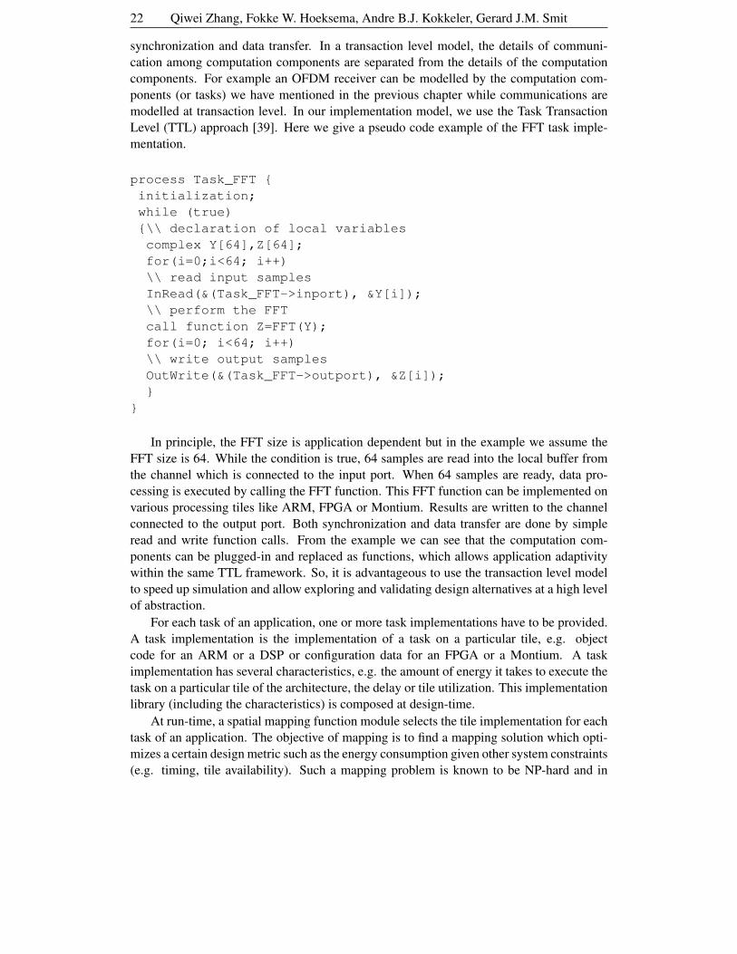
Level (TTL) approach [39]. Here we give a pseudo code example of the FFT task imple-
mentation.
process Task_FFT {
initialization;
while (true)
{\\ declaration of local variables
complex Y[64],Z[64];
for(i=0;i<64; i++)
\\ read input samples
InRead(&(Task_FFT->inport), &Y[i]);
\\ perform the FFT
call function Z=FFT(Y);
for(i=0; i<64; i++)
\\ write output samples
OutWrite(&(Task_FFT->outport), &Z[i]);
}
}
In principle, the FFT size is application dependent but in the example we assume the
FFT size is 64. While the condition is true, 64 samples are read into the local buffer from
the channel which is connected to the input port. When 64 samples are ready, data pro-
cessing is executed by calling the FFT function. This FFT function can be implemented on
various processing tiles like ARM, FPGA or Montium. Results are written to the channel
connected to the output port. Both synchronization and data transfer are done by simple
read and write function calls. From the example we can see that the computation com-
ponents can be plugged-in and replaced as functions, which allows application adaptivity
within the same TTL framework. So, it is advantageous to use the transaction level model
to speed up simulation and allow exploring and validating design alternatives at a high level
of abstraction.
For each task of an application, one or more task implementations have to be provided.
A task implementation is the implementation of a task on a particular tile, e.g. object
code for an ARM or a DSP or configuration data for an FPGA or a Montium. A task
implementation has several characteristics, e.g. the amount of energy it takes to execute the
task on a particular tile of the architecture, the delay or tile utilization. This implementation
library (including the characteristics) is composed at design-time.
At run-time, a spatial mapping function module selects the tile implementation for each
task of an application. The objective of mapping is to find a mapping solution which opti-
mizes a certain design metric such as the energy consumption given other system constraints
(e.g. timing, tile availability). Such a mapping problem is known to be NP-hard and in
Towards Cognitive Radio For Emergency Networks 23
practice, the corresponding optimization algorithms may run for hours. Therefore, heuris-
tics have to be used to find a solution with a reasonable quality within an acceptable time.
In [40], a minimal weight algorithm is proposed to map a digital audio broadcast receiver
onto a tiled SoC in a reasonable time, where the optimization metric is to minimize the
energy consumption. Run-time mapping offers a number of advantages over design-time
mapping, especially for a Cognitive Radio which dynamically changes its behavior.
• First, run-time mapping can adapt to the available resources. The available resources
may vary over time due to multiple applications running simultaneously.
• Second, run-time mapping can adapt to dynamically changing applications. A task
within the application may change its computational behavior at run-time, for exam-
ple, the size of the FFT or a new task can be added to the application.
5 Conclusion
In this chapter, we give an introduction into Cognitive Radio in the context of emergency
networks. Our focus on Cognitive Radio is to search for under-utilised spectrum and to
(rapidly) adapt transmission settings accordingly to meet various system requirements of
emergency networks. Therefore, the research on Cognitive Radio concentrates on frequency
scanning and adaptive baseband processing. Three architectures for single-node energy-
based scanning have been identified: scan-based, real-time FFT based and scanning-FFT
based. The scanning-FFT based approach is shown to be most promising. By introducing
collaboration between sensing nodes, an increase in detection quality can be expected.
The robustness to multipath delay spread and the hardware resource sharing with scan-
ning FFT-based spectrum sensing, make OFDM a good choice for the Cognitive Radio
baseband system. Moreover, OFDM systems that can nullify individual carriers poses in-
teresting opportunities for Cognitive Radio. A highly adaptive OFDM system is foreseen
since it has to operate in different frequency bands, it has to deal with various effects of
wireless channels like fading and shadowing and it has to support various multimedia ser-
vices. In order to support a flexible Cognitive Radio, a heterogenous reconfigurable SoC
platform is required, similar to a Software Defined Radio. The key element in the platform,
the coarse-grain reconfigurable tile processor (the Montium), enables the reconfigurabil-
ity in combination with the energy-efficiency. A design methodology is needed to map
applications onto a heterogeneous platform which has two new features: transaction level
modelling of applications and run-time spatial mapping.
References
[1] J. Mitola III. Cognitive Radio: An Integrated Agent Architecture for Software Defined
Radio. PhD thesis, Royal Institute of Technology, Sweden, May. 2000.
[2] S. Haykin. “Cognitive Radio: Brain-empowered Wireless Communication”. IEEE J.
Select. Areas Commun., vol. 23, no.2:pp 201–220, Feb. 2005.
[3] http://www.freeband.nl/project.cfm?id=488.
24 Qiwei Zhang, Fokke W. Hoeksema, Andre B.J. Kokkeler, Gerard J.M. Smit
[4] M. A. McHenry. “NSF spectrum occupancy meassurements project summary”.
http://www.sharespectrum.com.
[5] Tewfik L. Doumi. “Spectrum Considerations for Public Safety in the United States”.
IEEE Commun. Mag., Jan. 2006.
[6] T.A. Weiss and F.K. Jondral. “Spectrum Pooling: An Innovative Strategy for the
Enhancement of Spectrum Efficiency”. IEEE Commun. Mag., vol. 24, no.3:pp S8–
S14, Mar. 2004.
[7] J. Mitola. “Cognitive Radio: Making software radios more personal”. IEEE Pers.
Commun., Aug. 1999.
[8] Federal Communication Commision. “Spectrum Policy Task Force”. Tech. Report.,
Nov. 2002.
[9] Robert W. Brodersen, Adam Wolisz, Danijela Cabric, Shridhar Mubaraq Mishra,
Daniel Willkomm. “A Cognitive Radio Approach for Usage of Virtual Unlicensed
Spectrum”. White Paper, July 2004. http://bwrc.eecs.berkeley.edu/
Research/MCMA/CR_White_paper_final1.pdf.
[10] Shridhar Mubaraq Mishra et al. “A real time Cognitive Radio testded for physical
and link layer experiments”. In Proc. of the IEEE Symposium on New Frontiers in
Dynamic Spectrum Access, pages 562–567, Nov. 2005.
[11] http://bwrc.eecs.berkeley.edu/Research/Cognitive.
[12] T. Weiss, A. Krohn, J. Hillenbrand, and F. Jondral. “Mutual Interference in OFDM-
based Spectrum Pooling Systems”. In Proc of VTC, Milan, Italy, May 2004.
[13] http://www.cwt.vt.edu/research/cognitiveradio/index.html.
[14] Christian James Rieser. Biologically Inspired Cognitive Radio Engine Model Utilizing
Distributed Genetic Algorithms for Secure and Robust Wireless Communications and
Networking. PhD thesis, Virginia Tech.
[15] http://e2r.motlabs.com.
[16] http://www.ieee802.org/22.
[17] D. Cabric, S.M. Mishra, and R.W. Brodersen. “Implementation Issues in Spectrum
Sensing for Cognitive Radios”. 38th Asilomar conference on signals, systems and
computers, pages 772–776, 2004.
[18] M. Pelgrom. “Analog-to-digital Conversion”, March 2003. Course Notes University
of Twente, course 121048.
[19] K.H. Lundberg. “High-Speed Analog-to-Digital Converter Survey”, October 2002.
Accessible via http://web.mit.edu/klund/www/papers/.

Towards Cognitive Radio For Emergency Networks 25
[20] F.H. Sanders and V.S. Lawrence. “Broadband Spectrum Survey at Denver, Colorado”.
NTIA Report TR-95-321, NTIA, September 1995. http://www.its.bldrdoc.
gov/pub/surv_dnv/.
[21] M. McHenry and D. McCloskey. “New York City Spectrum Occupancy measure-
ments, September 2004”. Report, Shared Spectrum Company, December 2004.
[22] Agilent. “Spectrum Analyser Basics”. Application Note 150, Agilent, 2004.
[23] F.W. Hoeksema, M. Heskamp, R. Schiphorst, and C.H. Slump. “A Node Architecture
for Disaster Relief Networking”. 1st IEEE International Symposium on new Fron-
tiers in Dynamic Spectrum Access Networks(DySPAN’05), pages 577–584, Novem-
ber 2005.
[24] Agilent. “Swept and FFT Analysis”. Performance spectrum analyzer series - applica-
tion note, Agilent, 2004.
[25] Tektronics. “Fundamentals of Real-Time Spectrum Analysis”. Technical report, Tek-
tronics, 2004.
[26] Radiocommunications Agency The Netherlands) Dutch Ministry of Economic Affairs
(Agentschap Telecom. “Nationaal Frequentieplan 2005 (National Frequency Plan
2005)”. http://www.ez.nl/content.jsp?objectid=24642, February
2005.
[27] Radiocommunications Agency The Netherlands) Dutch Ministry of Economic Affairs
(Agentschap Telecom. “Nationaal Frequentieregister (National Frequency Register)”.
http://www.agentschap-telecom.nl/nfr/, March 2005.
[28] H.L. van Trees. Detection, Estimation, and Modulation Theory, volume I: Detection,
estimation, and Linear Modulation Theory. John Wiley & Sons, 1968.
[29] P.K. Varshney. Distributed Detection and Data Fusion. Springer-Verlag, 1997.
[30] I.Budiarjo, H.Nikookar, and L.P. Ligthart. “Overview of Adaptive OFDM in the Con-
text of Cognitive Radio”. In 12’th IEEE Symposium on Communications and Vehicu-
lar Technology in the BENELUX, Enschede, the Netherlands, Nov. 2005.
[31] ETSI. “Broadband Radio Access Networks (BRAN); HIPERLAN Type 2; Physical
(PHY) layer”. Technical Specification ETSI TS 101 475 V1.2.2 (2001-02), 2001.
[32] ETSI. “Radio broadcasting systems: Digital Audio Broadcasting to mobile, portable
and fixed receivers”. Technical Specification EN 300 401.
[33] ETSI. “Digital Radio Mondiale (DRM) System Specification”. Technical Specifica-
tion ETSI TS 101 980 V1.1.1 (2001-09), 2001.
[34] Gerard K. Rauwerda, Jordy Potman, Fokke W. Hoeksema, and Gerard J.M. Smit.
“Adaptation in the physical layer using heterogeneous reconfigurable hardware”. In
Adaptation Techniques in Wireless Multimedia Networks, 2006. ISBN 1-59454-883-8.

26 Qiwei Zhang, Fokke W. Hoeksema, Andre B.J. Kokkeler, Gerard J.M. Smit
[35] Paul M. Heysters. Coarse-Grained Reconfigurable Processors; Flexibility meets Effi-
ciency. PhD thesis, University of Twente, September 2004. ISBN 90-365-2076-2.
[36] Paul M. Heysters and Gerard J.M. Smit. “Mapping of DSP Algorithms on the Mon-
tium Architecture”. In Proceedings of Reconfigurable Achitecture Workshop, 2003.
[37] Gerard K. Rauwerda, Gerard J.M. Smit, and Werner Brugger. “Implementing an
Adaptive Viterbi Algorithm in Coarse-Grained Reconfigurable Hardware”. In Pro-
ceedings of the International Conference on Engineering of Reconfigurable Systems
and Algorithms, 2005.
[38] Arnaud Rivaton, Jerome Quevremont, Qiwei Zhang, Pascal T. Wolkotte, and Ger-
ard J.M. Smit. “Implementing Non Power-of-Two FFTs on Coarse-Grain Reconfig-
urable Architectures”. In Proceedings of the International Symposium on System-on-
Chip (SoC 2005), 2005.
[39] Pieter van der Wolf et al. “Design and Programming of Embedded Multiprocessors:
An Interface-Centric Approach”. In Proceedings of the CODES+ISSS, 2004.
[40] L.T. Smit, J.L. Hurink, and G.J.M. Smit. “Run-time mapping of applications to a het-
erogeneous SoC”. In IEEE 2005 International Symposium on System-on-Chip Pro-
ceedings, Tampere, Finland, 2005.