qi wireless charging led lantern reference design
TRANSCRIPT

2020 Microchip Technology Inc. DS50002992A
Qi Wireless Charging LED Lantern Reference Design

DS50002992A-page 2 2020 Microchip Technology Inc.
Information contained in this publication regarding deviceapplications and the like is provided only for your convenienceand may be superseded by updates. It is your responsibility toensure that your application meets with your specifications.MICROCHIP MAKES NO REPRESENTATIONS ORWARRANTIES OF ANY KIND WHETHER EXPRESS ORIMPLIED, WRITTEN OR ORAL, STATUTORY OROTHERWISE, RELATED TO THE INFORMATION,INCLUDING BUT NOT LIMITED TO ITS CONDITION,QUALITY, PERFORMANCE, MERCHANTABILITY ORFITNESS FOR PURPOSE. Microchip disclaims all liabilityarising from this information and its use. Use of Microchipdevices in life support and/or safety applications is entirely atthe buyer’s risk, and the buyer agrees to defend, indemnify andhold harmless Microchip from any and all damages, claims,suits, or expenses resulting from such use. No licenses areconveyed, implicitly or otherwise, under any Microchipintellectual property rights unless otherwise stated.
Note the following details of the code protection feature on Microchip devices:• Microchip products meet the specification contained in their particular Microchip Data Sheet.
• Microchip believes that its family of products is one of the most secure families of its kind on the market today, when used in the intended manner and under normal conditions.
• There are dishonest and possibly illegal methods used to breach the code protection feature. All of these methods, to our knowledge, require using the Microchip products in a manner outside the operating specifications contained in Microchip’s Data Sheets. Most likely, the person doing so is engaged in theft of intellectual property.
• Microchip is willing to work with the customer who is concerned about the integrity of their code.
• Neither Microchip nor any other semiconductor manufacturer can guarantee the security of their code. Code protection does not mean that we are guaranteeing the product as “unbreakable.”
Code protection is constantly evolving. We at Microchip are committed to continuously improving the code protection features of ourproducts. Attempts to break Microchip’s code protection feature may be a violation of the Digital Millennium Copyright Act. If such actsallow unauthorized access to your software or other copyrighted work, you may have a right to sue for relief under that Act.
TrademarksThe Microchip name and logo, the Microchip logo, Adaptec, AnyRate, AVR, AVR logo, AVR Freaks, BesTime, BitCloud, chipKIT, chipKIT logo, CryptoMemory, CryptoRF, dsPIC, FlashFlex, flexPWR, HELDO, IGLOO, JukeBlox, KeeLoq, Kleer, LANCheck, LinkMD, maXStylus, maXTouch, MediaLB, megaAVR, Microsemi, Microsemi logo, MOST, MOST logo, MPLAB, OptoLyzer, PackeTime, PIC, picoPower, PICSTART, PIC32 logo, PolarFire, Prochip Designer, QTouch, SAM-BA, SenGenuity, SpyNIC, SST, SST Logo, SuperFlash, Symmetricom, SyncServer, Tachyon, TempTrackr, TimeSource, tinyAVR, UNI/O, Vectron, and XMEGA are registered trademarks of Microchip Technology Incorporated in the U.S.A. and other countries.
APT, ClockWorks, The Embedded Control Solutions Company, EtherSynch, FlashTec, Hyper Speed Control, HyperLight Load, IntelliMOS, Libero, motorBench, mTouch, Powermite 3, Precision Edge, ProASIC, ProASIC Plus, ProASIC Plus logo, Quiet-Wire, SmartFusion, SyncWorld, Temux, TimeCesium, TimeHub, TimePictra, TimeProvider, Vite, WinPath, and ZL are registered trademarks of Microchip Technology Incorporated in the U.S.A.
Adjacent Key Suppression, AKS, Analog-for-the-Digital Age, Any Capacitor, AnyIn, AnyOut, BlueSky, BodyCom, CodeGuard, CryptoAuthentication, CryptoAutomotive, CryptoCompanion, CryptoController, dsPICDEM, dsPICDEM.net, Dynamic Average Matching, DAM, ECAN, EtherGREEN, In-Circuit Serial Programming, ICSP, INICnet, Inter-Chip Connectivity, JitterBlocker, KleerNet, KleerNet logo, memBrain, Mindi, MiWi, MPASM, MPF, MPLAB Certified logo, MPLIB, MPLINK, MultiTRAK, NetDetach, Omniscient Code Generation, PICDEM, PICDEM.net, PICkit, PICtail, PowerSmart, PureSilicon, QMatrix, REAL ICE, Ripple Blocker, SAM-ICE, Serial Quad I/O, SMART-I.S., SQI, SuperSwitcher, SuperSwitcher II, Total Endurance, TSHARC, USBCheck, VariSense, ViewSpan, WiperLock, Wireless DNA, and ZENA are trademarks of Microchip Technology Incorporated in the U.S.A. and other countries.
SQTP is a service mark of Microchip Technology Incorporated in the U.S.A.The Adaptec logo, Frequency on Demand, Silicon Storage Technology, and Symmcom are registered trademarks of Microchip Technology Inc. in other countries.GestIC is a registered trademark of Microchip Technology Germany II GmbH & Co. KG, a subsidiary of Microchip Technology Inc., in other countries. All other trademarks mentioned herein are property of their respective companies.
© 2020, Microchip Technology Incorporated, All Rights Reserved.
ISBN: 978-1-5224-6093-0For information regarding Microchip’s Quality Management Systems, please visit www.microchip.com/quality.

QI WIRELESS CHARGING LED LANTERN
REFERENCE DESIGN Table of Contents
Chapter 1. Product Overview1.1 Introduction ..................................................................................................... 51.2 Qi Wireless Charging LED Lantern Reference Design Overview .................. 5
1.2.1 Device Overview ........................................................................................ 51.2.2 What is the Qi Wireless Charging LED Lantern Reference Design? ........... 5
1.3 What the Qi Wireless Charging LED Lantern Kit Contains ............................ 5Chapter 2. Installation and Operation
2.1 Introduction ..................................................................................................... 72.1.1 Qi Wireless Charging LED Lantern Key Features ....................................... 72.1.2 Qi Wireless Charging LED Lantern Reference Design Features ................ 7
2.2 Getting Started ............................................................................................... 82.2.1 Setup and Testing ....................................................................................... 82.2.2 How the Qi Wireless Charging LED Lantern Reference Design works ....... 92.2.3 Firmware Description ................................................................................. 10
Appendix A. Schematics and LayoutsA.1 Introduction .................................................................................................. 11A.2 Board – Schematic ....................................................................................... 12A.3 Board – Top Silk .......................................................................................... 13A.4 Board – Top Copper and Silk ....................................................................... 13A.5 Board – Top Copper .................................................................................... 14A.6 Board – Bottom Copper ............................................................................... 14A.7 Board – Bottom Copper and Silk ................................................................. 15A.8 Board – Bottom Silk ..................................................................................... 15
Appendix B. Bill of Materials (BOM)Worldwide Sales and Service .................................................................................... 19
2020 Microchip Technology Inc. DS50002992A-page 3

Qi Wireless Charging LED Lantern Reference Design
NOTES:
DS50002992A-page 4 2020 Microchip Technology Inc.

QI WIRELESS CHARGING LED LANTERN
REFERENCE DESIGN
Chapter 1. Product Overview
1.1 INTRODUCTIONThis chapter provides an overview of the Qi Wireless Charging LED Lantern Reference Design and covers the following topics:• Qi Wireless Charging LED Lantern Reference Design Short Overview• What is the Qi Wireless Charging LED Lantern Reference Design?• Qi Wireless Charging LED Lantern Reference Design Kit Contents
1.2 QI WIRELESS CHARGING LED LANTERN REFERENCE DESIGN OVERVIEW
1.2.1 Device OverviewThe Microchip Qi Wireless Charging LED Lantern is a Qi 1.1 standard (5W maximum power) compatible receiver. It provides a flexible, low-cost alternative to the common wireless charging solutions by using a general purpose 8-bit microcontroller for communication and charging.The Microchip Qi Wireless Charging LED Lantern can be used in conjunction with any Qi 1.1 - compatible wireless charging transmitters. It has the added functionality of a fully featured Lithium-Ion charging controller and the high efficiency of a switching power supply.
1.2.2 What is the Qi Wireless Charging LED Lantern Reference Design?
The Qi Wireless Charging LED Lantern Reference Design is a portable and flexible lighting solution which can be charged wirelessly. The design demonstrates features of a Qi 1.1 compatible wireless receiver which opens the possibility of encapsulating the end solution, making it dust and waterproof.A synchronous, bidirectional buck or boost converter is used in order to obtain high effi-ciency and to implement the battery charging algorithm and the LED driving functions. A full charging algorithm for Lithium-Ion batteries is implemented in the microcontrol-ler's firmware, providing safe charging.The lantern’s lighting intensity can be selected with the help of a button, having four dimming levels. A 14-pin PIC16F18325 microcontroller is used to implement all the functions on the board (Qi communication protocol, buck and boost regulation's con-trol, battery charging algorithm, LED dimming).
1.3 WHAT THE QI WIRELESS CHARGING LED LANTERN KIT CONTAINSThe Qi Wireless Charging LED Lantern Reference Design kit includes:• Qi Wireless Charging LED Lantern Reference Design LED Board• Important Information Sheet
2020 Microchip Technology Inc. DS50002992A-page 5
Qi Wireless Charging LED Lantern Reference Design
NOTES:
DS50002992A-page 6 2020 Microchip Technology Inc.

QI WIRELESS CHARGING LED LANTERN
REFERENCE DESIGNChapter 2. Installation and Operation
2.1 INTRODUCTION
2.1.1 Qi Wireless Charging LED Lantern Key Features The Microchip Qi Wireless Charging LED Lantern is developed to offer a flexible, low-cost alternative demo solution to the already existing wireless charging products.The key features of the Microchip Qi Wireless Charging LED Lantern that allow the users to quickly add accessible wireless charging functionality to other applications are:• Receiver implementation using a general purpose 8-bit microcontroller• Compatibility with the Qi 1.1 (5W) standard, allowing the receiver to be used with
any Qi 1.1 compatible wireless charging transmitters• Accurate power measurement to aid the Foreign Object Detection (FOD) function
2.1.2 Qi Wireless Charging LED Lantern Reference Design Features The Qi Wireless Charging LED Lantern Reference Design is developed to demonstrate a Qi 1.1 receiver implementation coupled with a bidirectional switching power supply that enables battery charging and LED driving. The board demonstrates how to implement a Qi 1.1 wireless receiver, charge a Lithium-Ion battery from a receiver and boost the battery voltage to drive a string of LEDs, using a PIC16F18325 microcontroller and a number of analog components.
FIGURE 2-1: Qi Wireless Charging LED Lantern Reference Design Simplified Block Diagram.
2020 Microchip Technology Inc. DS50002992A-page 7

Qi Wireless Charging LED Lantern Reference Design
The Qi Wireless Charging LED Lantern Reference Design has the following features:• Input voltage from wireless receiver coil: +4.5V to +28V• Low voltage power: +5V (using a MCP1804 LDO) • Qi 1.1 5W Wireless Charger communication protocol implemented in microcon-
troller's firmware• Designed to use 2000 mAh Li-Ion battery (charging 1A at 4.2V)• 3 LEDs string (200 mA max. driving current at 9V) • Synchronous buck converter topology, leading to high efficiency• Bidirectional buck or boost converter, driven by a PFM signal, providing charging
and discharging modes, buck mode in order to charge the battery and boost mode to supply the LED string from the battery
• Full charging algorithm for Lithium-Ion batteries implemented in firmware• Four dimming levels for LEDs: 25%, 50%, 75% and 100%
2.2 GETTING STARTEDThe Qi Wireless Charging LED Lantern Reference Design is fully assembled and tested to evaluate and demonstrate the Microchip Qi Wireless Charging LED Lantern product.
2.2.1 Setup and Testing
2.2.1.1 SETTING UP THE BOARD
Take the following steps to use the device:• A battery that meets the requirements in Note 1 must be attached to the
designated connector• Power on the board by placing the lateral switch (SW2) in the ON position• To charge the battery connected to the board:
- Make sure the lantern function is OFF (LEDs are turned OFF)- Place the board on the wireless charger to charge the battery- Wait until the LEDs start flashing, indicating full charge
• To use the lantern function: - Push the SW1 button to turn on the light - Choose the dimming level by pressing the button repeatedly until the desired
level is selected
2.2.1.2 BOARD TESTING
The best way to evaluate the Qi Wireless Charging Lantern is to examine the circuit and measure the voltages and currents with a digital voltage meter and probe the board with an oscilloscope.The coil voltage and battery voltage can be measured directly or on voltage dividers. The battery current can be measured at the output of the MCP6001 operational amplifier or on the battery shunt resistor (R12). The current through LEDs can be measured on dedicated shunt resistor(R5).
Note 1: A Li-Ion battery with a 2 pin connector and a capacity of around 2000 mAh is needed for the board to function correctly. The circuit needs to be powered by the battery to start communicating with and charging from the wireless charging station. For testing purposes, a HobbyKing® 9067000191-0 Li-Ion battery is used.
DS50002992A-page 8 2020 Microchip Technology Inc.

Installation and Operation
FIGURE 2-2: Qi Wireless Charging LED Lantern Reference Design Setup Circuit.
2.2.2 How the Qi Wireless Charging LED Lantern Reference Design works
The Qi charger incorporates the Qi 1.1 standard for wireless power transfer, making it a portable device. It brings the advantage of not needing any connector for charging, making the device easy to encapsulate so it can be made waterproof.A synchronous buck converter is used to charge the Lithium-Ion (Li-Ion) battery. The input voltage is provided by the Qi charger. A complex charging algorithm is implemented in the firmware. The algorithm incorporates the precharge state, constant current and constant voltage stages until one of the End-of-Charge conditions is reached (minimum current, flat current or timeout). The battery is considered charged when it reaches 4.2V and the charging current drops below 200 mA. The Lithium-Ion battery current is measured using the MCP6001 low-power operational amplifier.The DC converter is bidirectional and its regulation loop is controlled by the PIC microcontroller. The power train is driven by a MCP14628 MOSFET Power Driver. When the lantern needs to be powered, the PFM signal polarity is inverted. The MCP14628 driver is set to forced continuous conduction mode (CCM) and the converter turns into a boost mode which supplies the LEDs. The maximum current through the LEDs is set to 200 mA.Four programmable levels of intensity are provided for the LEDs. The level is selected by pressing the button. Modifying the level is complete by changing the current reference. An 8-bit microcontroller, PIC16F18325, is used to select and control the charge/dis-charge modes, measure the battery voltage and current, enable the current through LEDs during discharge and select the current reference for the desired dimming level.The MCP1804 Low-Dropout Regulator (LDO) is used to supply with +5V the PIC16F18325 microcontroller, the MCP14628 MOSFET driver and the MCP6001 low-power operational amplifier.
2020 Microchip Technology Inc. DS50002992A-page 9
Qi Wireless Charging LED Lantern Reference Design
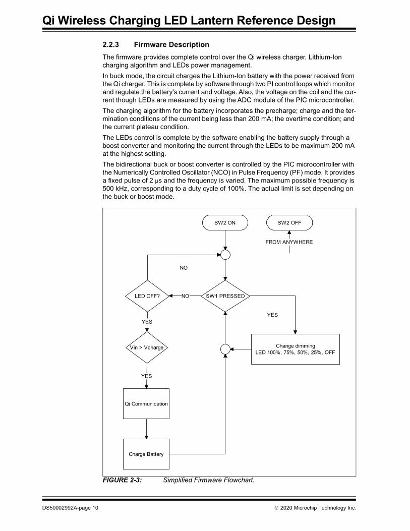
2.2.3 Firmware DescriptionThe firmware provides complete control over the Qi wireless charger, Lithium-Ion charging algorithm and LEDs power management.In buck mode, the circuit charges the Lithium-Ion battery with the power received from the Qi charger. This is complete by software through two PI control loops which monitor and regulate the battery's current and voltage. Also, the voltage on the coil and the cur-rent though LEDs are measured by using the ADC module of the PIC microcontroller. The charging algorithm for the battery incorporates the precharge; charge and the ter-mination conditions of the current being less than 200 mA; the overtime condition; and the current plateau condition. The LEDs control is complete by the software enabling the battery supply through a boost converter and monitoring the current through the LEDs to be maximum 200 mA at the highest setting.The bidirectional buck or boost converter is controlled by the PIC microcontroller with the Numerically Controlled Oscillator (NCO) in Pulse Frequency (PF) mode. It provides a fixed pulse of 2 µs and the frequency is varied. The maximum possible frequency is 500 kHz, corresponding to a duty cycle of 100%. The actual limit is set depending on the buck or boost mode.
FIGURE 2-3: Simplified Firmware Flowchart.
SW2 ON
LED OFF?
Change dimmingLED 100%, 75%, 50%, 25%, OFF
SW1 PRESSED
Vin > Vcharge
YESYES
Qi Communication
Charge Battery
YESYES
NONO
YESYES
SW2 OFF
FROM ANYWHEREFROM ANYWHERE
NONO
DS50002992A-page 10 2020 Microchip Technology Inc.

QI WIRELESS CHARGING LED LANTERN
REFERENCE DESIGNAppendix A. Schematics and Layouts
A.1 INTRODUCTIONThis appendix contains the following schematics and layouts for the Qi Wireless Charging LED Lantern Reference Design:• Board – Schematic• Board – Top Silk• Board – Top Copper and Silk• Board – Top Copper• Board – Bottom Copper• Board – Bottom Copper and Silk• Board – Bottom Silk
2020 Microchip Technology Inc. DS50002992A-page 11

Schematics and Layouts
2020 M
icrochip Technology Inc.D
S50002992A-page 12
A.
Qi Lantern Wireless BatteryProject Title
Designed with
Drawn By:Mihnea Rosu
Sheet Title
Qi Lantern Wireless Battery
Engineer:Mihnea Rosu
INT01115PartNumber: Variant: [No Variations]
VDD1
RA52
RA43
RA3/MCLR/VPP4
RC55
RC46
RC37
RC28
RC19
RC010
RA211
RA1/ICSPCLK12
RA0/ICSPDAT13
VSS14
PIC16F18325
IC1+5V
VIN_DIVVBAT_DIV
ILEDPGC/DATA_MODDAC_OUT/PGD
MCLR/BUTIN_SWLED_SW
FCCMPIC_BSTPIC_PFMIBAT
0.1uF25V0603
C20
T
10k06031%
R4
20k06031%
R2
VBAT
F
3
ILED
VBAT_DIV
+A3
-A4
OUTA1
VSS
2
VDD
5
+A
-A
OUTA
VSS
VDD
A
S
D
MCP6001U2
0.05RR12
GND
+5V
GND
1k
R10
1k
R7
1k
R6
GND
10000pFC19
GND
IBAT
GND
GND GND
BATTERY
1000pF50V0603
C1
+5V
GND
0.1uF25V0603
C28
12
J5
31
2
25336NA
SW2
3.7V Li-Poly
BAT1
2 BOARD – SCHEMATIC
DAC_OUT/PGDPGC/DATA_MOD
+5V
HIGHDR1
BO
OT
2
PWM3
GN
D4
LOWDR5
VC
C6
FC
CM
7
PHASE8
MCP14628IC2
1uF25V0603
C22
DRV_VDD
PIC_PFM
PHASE
100k06031%
R17DRV_VDD
FCCM
LO_DRV
HI_DRV1N4148
D7
VIN +5V VBAT
VIN1
GND2
SHDN4
NC3
VOUT5
MCP1804/5V
U1
0.1uF50V0805
C21
0.1uF50V0603
C25
8uHL1
15uH
L2
3
1
2
Q53
1
2
Q6
1uF25V0603
C23
10uF25V0603
C240.1uF25V0603
C26
DRV_VDD
0.1uF25V0603
C27
PIC_BST
PGC/DATA_MODPGC/DATA_MOD
0.1uF50V 1206C3
0.1uF50V 1206C4
0.047uF50V0805
C160.047uF50V0805
C17
10uF50V1206
C510uF50V1206
C6
VIN_RECT
41,
2,3
5,6,7
,8
NTMS4177PR2GQ2
10k06031%
R9
3
1
2
Q4IN_SW
10uF50V1206
C710uF50V1206
C810uF50V1206
C910uF50V1206
C10
VIN
110k06031%
R8
10k06031%
R11
8
2
17 ,
SI4804CDY-T1-GE3Q3A
5
4
36 ,
SI4804CDY-T1-GE3Q3B
HI_DRV
LO_DRV10uF50V1206
C1210uF50V1206
C1310uF50V1206
C1410uF50V1206
C15
VBA
1R08051%
R5
1k06031%
R3
27p50V060
C2
VIN_DIV
12
J2
1 2J3
DRV_VDD
GND
GND
GND GND
GNDGNDGND
GND
GND
GNDGND
GNDGND
GND
3
1
2
2N7002-7-FQ1
GND
GND GND GND GND GND GND
GND
MCLR/BUT
+5V
PMEG3030EP
D1
PM
EG
30
30
EP
D3
PMEG3030EP
D4PMEG3030EPD2
1000pF50V0603
C18
10k06031%
R1
5600pF50V0805
C11
PHASE
LED_SW
TACT SPST
SW1
123456
HDR-2.54 Male 1x6
J1
TP1
GND
GND
TP4
TP5
MCLR/BUT
5.1VD6
123
BAV99D5

Schematics and Layouts
A.3 BOARD – TOP SILK
A.4 BOARD – TOP COPPER AND SILK
2020 Microchip Technology Inc. DS50002992A-page 13

Qi Wireless Charging LED Lantern Reference Design
A.5 BOARD – TOP COPPER
A.6 BOARD – BOTTOM COPPER
DS50002992A-page 14 2020 Microchip Technology Inc.

Schematics and Layouts
A.7 BOARD – BOTTOM COPPER AND SILK
A.8 BOARD – BOTTOM SILK
2020 Microchip Technology Inc. DS50002992A-page 15

Qi Wireless Charging LED Lantern Reference Design
NOTES:
DS50002992A-page 16 2020 Microchip Technology Inc.

QI WIRELESS CHARGING LED LANTERN
REFERENCE DESIGN
Appendix B. Bill of Materials (BOM)
TABLE B-1: BILL OF MATERIALS (BOM)Qty. Reference Description Manufacturer Part Number2 C1, C18 Capacitor, ceramic,1000 pF, 50V,
20%, X7R, SMD, 0603TDK Corporation C1608X7R2A102K080AA
1 C2 Capacitor, ceramic, 27 pF, 50V, 5%, NP0, SMD, 0603
KEMET C0603C270J5GACTU
2 C3, C4 Capacitor, ceramic, 0.1 µF, 50V, 10%, X7R, SMD, 1206
Murata Electronics® GRM42-6X7R104K050BL
10 C5, C6, C7, C8, C9, C10, C12, C13, C14, C15
Capacitor, ceramic, 10 µF, 50V, 10%, X5R, SMD, 1206
Wurth Electronik 885012108022
1 C11 Capacitor, ceramic, 5600 pF, 50V, 5%, NP0, SMD, 0805
KEMET C0805C562J5GACTU
2 C16, C17 Capacitor, ceramic, 0.047 µF, 50V, 10%, X7R, SMD, 0805
KEMET C0805C473K5RACTU
1 C19 Capacitor, ceramic, 10000 pF, 50V, 10%, X7R, SMD, 0603
Kyocera AVX® 06035C103KAT2A\4K
4 C20, C26, C27, C28
Capacitor, ceramic, 0.1 µF, 25V, 20%, X7R, SMD, 0603
KEMET C0603C104M3RACTU
1 C21 Capacitor, ceramic, 0.1 µF, 50V, 10%, X7R, SMD, 0805
Kyocera AVX 08055C104KAT2A
2 C22,C23 Capacitor, ceramic, 1 µF, 25V, 10%, X7R, SMD, 0603
TDK Corporation CGA3E1X7R1E105K080AC
1 C24 Capacitor, ceramic,10 µF, 25V, 20%, X5R, SMD, 0603
Murata Electronics GRM188R61E106MA73D
1 C25 Capacitor, ceramic, 0.1 µF, 50V, 10%, X7R, SMD, 0603
Yageo Corporation CC0603KRX7R9BB104
4 D1,D2,D3,D4 Diode SCTKY PMEG3030EP,115, 30V, 3A, SMD, SOD-128
Nexperia PMEG3030EP,115
1 D5 Diode RECT ARRAY BAV99, 1.25V, 200 mA, 70V, SOT-23-3
Micro Commercial Components Corporation®
BAV99-TP
1 D6 Diode NR MMSZ4689ET1G, 5.1V, 500mW, SMD, SOD-123
ON Semiconductor® MMSZ4689ET1G
1 D7 Diode RECT 1N4148 1.25V, 150 mA, 100V, SOD-123
Micro Commercial Components Corporation
1N4148W-TP
1 J1 Connector HDR-2.54, Male, 1x6 Tin, 5.84 MH, TH, VERT
Sullins Connector Solutions
PEC06SAAN
Note: The components listed in this Bill of Materials are representative of the PCB assembly. The released BOM used in manufacturing uses all RoHS-compliant components.
2020 Microchip Technology Inc. DS50002992A-page 17

Qi Wireless Charging LED Lantern Reference Design
2 J2,J3 Connector HDR-2.54, Male, 1x2, Gold, 5.84 MH, TH, VERT
Wurth Electronik 61300211121
1 J5 Connector HDR-2.0, Male, 1X2, SHROUDED B2B-PH-K-S(LF)(SN), TH, VERT
JST B2B-PH-K-S(LF)(SN)
1 L1 Inductor, 8 µH, 5A, 10%, L40W40H1.2, Wireless Power Charging Reciever Coil
Wurth Electronik 760308102207
1 L2 Inductor, 15 µH, 2.2A, 15%, SMD, 7.3x7.3x4.5
Wurth Electronik 7447779115
1 Q1 Transistor FET, N-CH, 2N7002-7-F, 60V, 170 mA, 370 mW, SOT-23-3
NXP Semiconductors 2N7002-7-F
1 Q2 Transistor FET, P-CH, NTMS4177PR2G, 30V, 6.6A, 0.012R, 0.84W, SOIC-8
ON Semiconductor NTMS4177PR2G
1 Q3 Transistor FET DUAL, N+N, SI4804CDY-T1-GE3, 30V, 8A, 0.022R, 3.1W, SOIC-8
Vishay Siliconix SI4804CDY-T1-GE3
4 Q4, Q5, Q6 Transistor FET, N-CH, 2N7002P,215, 60V, 360 mA, 350 mW, SOT-23-3
Nexperia USA 2N7002P,215
4 R1, R4, R9,R11
Resistor, TKF, 10k, 1%, 1/10W, SMD, 0603
Panasonic® - ECG ERJ-3GEYJ132V
1 R2 Resistor, TKF, 100k, 1%, 1/10W, SMD, 0603
Panasonic - ECG 5-1879337-9
4 R3, R6, R7,R10
Resistor, TKF, 1k, 1%, 1/10W, SMD, 0603
Panasonic - ECG ERJ-3EKF8201V
1 R5 Resistor, TKF, 1R, 1%, 1/8W, SMD, 0805
Panasonic - ECG ERJ-3EKF3003V
1 R8 Resistor, TKF, 110k, 1%, 1/10W, SMD, 0603
Vishay Dale ERJ-3EKF2001V
1 R12 Resistor, MS, 0.05R, 1%, 1W, SMD, 1206
TE Connectivity, Ltd. ERJ-3EKF3301V
1 R17 Resistor, TKF, 100k, 1%, 1/2W, SMD, 0603
Panasonic - ECG ERJ-3EKF1004V
1 SW1 Switch, TACT, SPST, 12V, 50 mA, EVQ-P7A01P SMD
Panasonic - ECG ERJ-6BWFR025V
1 SW2 Switch, SLIDE, SPDT, 1A, 30VDC, RA, TH
APEM CRCW0603470KFKEA
1 TP1 CON TP LOOP Black TH Keystone Electronic ERJ-3EKF5902VIC1 Microchip, MCU, 8-BIT, 32 MHz,
14kB, 1K, PIC16F18325-I/SL SOIC-14
Microchip Technology Inc. PIC16F18325-I/SL
IC2 Microchip Analog FET Driver, Sin-gle-Non-Inverting, MCP14628-E/SN SOIC-8
Microchip Technology Inc. MCP14628T-E/SN
1 U1 Microchip Analog LDO 5V MCP1804T-5002I/OT SOT-23-5
Microchip Technology Inc. MCP1804T-5002I/OT
1 U2 Microchip Analog OPAMP 1-Ch 1MHz MCP6001T-E/OT SOT-23-5
Microchip Technology Inc. MCP6001T-E/OT
TABLE B-1: BILL OF MATERIALS (BOM) (CONTINUED)Qty. Reference Description Manufacturer Part Number
Note: The components listed in this Bill of Materials are representative of the PCB assembly. The released BOM used in manufacturing uses all RoHS-compliant components.
DS50002992A-page 18 2020 Microchip Technology Inc.

DS50002992A-page 19 2020 Microchip Technology Inc.
AMERICASCorporate Office2355 West Chandler Blvd.Chandler, AZ 85224-6199Tel: 480-792-7200 Fax: 480-792-7277Technical Support: http://www.microchip.com/supportWeb Address: www.microchip.comAtlantaDuluth, GA Tel: 678-957-9614 Fax: 678-957-1455Austin, TXTel: 512-257-3370 BostonWestborough, MA Tel: 774-760-0087 Fax: 774-760-0088ChicagoItasca, IL Tel: 630-285-0071 Fax: 630-285-0075DallasAddison, TX Tel: 972-818-7423 Fax: 972-818-2924DetroitNovi, MI Tel: 248-848-4000Houston, TX Tel: 281-894-5983IndianapolisNoblesville, IN Tel: 317-773-8323Fax: 317-773-5453Tel: 317-536-2380Los AngelesMission Viejo, CA Tel: 949-462-9523Fax: 949-462-9608Tel: 951-273-7800 Raleigh, NC Tel: 919-844-7510New York, NY Tel: 631-435-6000San Jose, CA Tel: 408-735-9110Tel: 408-436-4270Canada - TorontoTel: 905-695-1980 Fax: 905-695-2078
ASIA/PACIFICAustralia - SydneyTel: 61-2-9868-6733China - BeijingTel: 86-10-8569-7000 China - ChengduTel: 86-28-8665-5511China - ChongqingTel: 86-23-8980-9588China - DongguanTel: 86-769-8702-9880 China - GuangzhouTel: 86-20-8755-8029 China - HangzhouTel: 86-571-8792-8115 China - Hong Kong SARTel: 852-2943-5100 China - NanjingTel: 86-25-8473-2460China - QingdaoTel: 86-532-8502-7355China - ShanghaiTel: 86-21-3326-8000 China - ShenyangTel: 86-24-2334-2829China - ShenzhenTel: 86-755-8864-2200 China - SuzhouTel: 86-186-6233-1526 China - WuhanTel: 86-27-5980-5300China - XianTel: 86-29-8833-7252China - XiamenTel: 86-592-2388138 China - ZhuhaiTel: 86-756-3210040
ASIA/PACIFICIndia - BangaloreTel: 91-80-3090-4444 India - New DelhiTel: 91-11-4160-8631India - PuneTel: 91-20-4121-0141Japan - OsakaTel: 81-6-6152-7160 Japan - TokyoTel: 81-3-6880- 3770 Korea - DaeguTel: 82-53-744-4301Korea - SeoulTel: 82-2-554-7200Malaysia - Kuala LumpurTel: 60-3-7651-7906Malaysia - PenangTel: 60-4-227-8870Philippines - ManilaTel: 63-2-634-9065SingaporeTel: 65-6334-8870Taiwan - Hsin ChuTel: 886-3-577-8366Taiwan - KaohsiungTel: 886-7-213-7830Taiwan - TaipeiTel: 886-2-2508-8600 Thailand - BangkokTel: 66-2-694-1351Vietnam - Ho Chi MinhTel: 84-28-5448-2100
EUROPEAustria - WelsTel: 43-7242-2244-39Fax: 43-7242-2244-393Denmark - CopenhagenTel: 45-4485-5910 Fax: 45-4485-2829Finland - EspooTel: 358-9-4520-820France - ParisTel: 33-1-69-53-63-20 Fax: 33-1-69-30-90-79 Germany - GarchingTel: 49-8931-9700Germany - HaanTel: 49-2129-3766400Germany - HeilbronnTel: 49-7131-72400Germany - KarlsruheTel: 49-721-625370Germany - MunichTel: 49-89-627-144-0 Fax: 49-89-627-144-44Germany - RosenheimTel: 49-8031-354-560Israel - Ra’anana Tel: 972-9-744-7705Italy - Milan Tel: 39-0331-742611 Fax: 39-0331-466781Italy - PadovaTel: 39-049-7625286 Netherlands - DrunenTel: 31-416-690399 Fax: 31-416-690340Norway - TrondheimTel: 47-7288-4388Poland - WarsawTel: 48-22-3325737 Romania - BucharestTel: 40-21-407-87-50Spain - MadridTel: 34-91-708-08-90Fax: 34-91-708-08-91Sweden - GothenbergTel: 46-31-704-60-40Sweden - StockholmTel: 46-8-5090-4654UK - WokinghamTel: 44-118-921-5800Fax: 44-118-921-5820
Worldwide Sales and Service
02/28/20