qft control of a two-link rigid-flexible manipulator
DESCRIPTION
This paper evaluates a new and simple controller design method based on QFT (quantitative feedback theory) for a two-link manipulator whose first link is rigid and the second is flexible. A piezoelectric patch is attached to the surface of the flexible link for vibration suppression of it. This system is modeled as a nonlinear multi-input multi-output (MIMO) control systems whose inputs are two motor torques which are applied on the joints and a voltage which is applied on the piezoelectric patch. To control the manipulatorâ s end point position, motion of the manipulator is divided to two rigid and flexible parts. To control both parts, nonlinear equations of the motion is replaced by a family of uncertain linear time-invariant equivalent systems using Rafeeyan-Sobhaniâ s method(RS method) which results in three decoupled transfer functions established in the Laplace domain. Then the QFT method is used to design a diagonal matrix as the prefilter of the system an another diagonal maTRANSCRIPT

International Journal of Robotics, Vol.3, No.1, (2013)/M. S. Mirshamsi, M. Mirshamsi
49
QFT Control of a Two-Link Rigid-Flexible Manipulator
Malihe Sadat Mirshamsia, Mansour Rafeeyana
a-Department of Mechanical Engineering, Yazd University, Yazd, Iran
A R T I C L E I N F O A B S T R A C T Keywords: rigid-flexible manipulator, quantitative feedback theory, control, piezoelectric.
This paper evaluates a new and simple controller design method based on QFT (quantitative feedback theory) for a two-link manipulator whose first link is rigid and the second is flexible. A piezoelectric patch is attached to the surface of the flexible link for vibration suppression of it. This system is modeled as a nonlinear multi-input multi-output (MIMO) control systems whose inputs are two motor torques which are applied on the joints and a voltage which is applied on the piezoelectric patch. To control the manipulator’s end point position, motion of the manipulator is divided to two rigid and flexible parts. To control both parts, nonlinear equations of the motion is replaced by a family of uncertain linear time-invariant equivalent systems using Rafeeyan-Sobhani’s method(RS method) which results in three decoupled transfer functions established in the Laplace domain. Then the QFT method is used to design a diagonal matrix as the prefilter of the system an another diagonal matrix as the system controller. Results demonstrate the remarkable performance of the proposed controllers in reduction of residual vibration of elastic link and tracking a circular trajectory by the manipulator end point.
1. Introduction In the last two decades, the modeling and control
of lightweight manipulators has attracted the serious attention of researchers due to their excellent characteristics. Compared with their rigid-arm counterparts, flexible manipulators have the advantages of less material and power consumption, larger workspace, higher operation speed, smaller actuators and more maneuverability. However, the disadvantages of lightweight manipulators are the elastic deformation and tip vibration caused by the structural flexibility of the long reach and slender links. As a consequence, the tip position and orientation of flexible manipulators are difficult to control. Thus, trajectory following control of robotic manipulator system has been an important research area in the last decade([1]-[3]). Most of the proposed control strategies in the literature require knowledge of an accurate mathematical model of the system and the stability of the closed-loop system critically depends on how well the actual flexible manipulator dynamics is modeled. In real applications, however, the inertial and elastic characteristics of a flexible manipulator are not known precisely. More control
difficulties such as distributed parameter nature of the system, highly nonlinearity and rigid mode coupling effects compensation, are encountered while controlling flexible robots. To this end, the solutions suggested in the literature involve use of adaptive methods [4], the robust controllers ([5], [6]), soft computing approaches such as fuzzy logic and neural network techniques ([7]-[9]). One of the robust control strategies based on the classical frequency domain is the quantitative feedback theory (QFT) [10]. The inherent characteristics of the QFT control include robustness of the performance to structured plant uncertainties, avoidance of noise amplification, fast adaptability of redesign for desirable specifications and transparency between dynamics and control specifications. Choi et al. proposed a control method based on QFT for robust position control of a single-link flexible manipulator [11]. The off-diagonal elements of the inertia matrix are separated as system disturbance and transfer functions of system are decoupled. Then, two QFT type compensators are designed for two actuators on the basis of a stability criterion which specifies disturbance rejection and tracking performance

International Journal of Robotics, Vol.3, No.1, (2013)/M. S. Mirshamsi, M. Mirshamsi
50
bounds.This proposedapproach cannot be extended to flexible manipulators that have more than one link.
In this paper, a controller design method based on QFT is used for a two-link rigid-flexible manipulator system. To control the manipulator’s end point position for accurate tracking of a desired trajectory, motion of the manipulator is divided to two rigid and flexible parts. To control the rigid part of the motion, nonlinear equations of the motion of a two link rigid manipulator is replaced by a family of uncertain linear time-invariant equivalent systems using Rafeeyan-Sobhani’s method [12] which results in two decoupled transfer functions established in the Laplace domain; one is from input torque of the first motor to the first output hub angle and the other is from input torque of the second motor to the second output hub angle. To control the flexible part of motion, the third equation of the motion of the two-link rigid-flexible manipulator (elastic deflection equation) is treated in the same approach (RS method) and another transfer function is obtained. This transfer function is from input voltage to output tip-deflection of the second link. Since the equations of motion are decoupled by the RS method, the three input-three output robot system is reduced to three uncertain and linear single input-single output systems. Then the QFT method (a known robust control method) is used for each of these SISO systems. Thus, three controllers and prefilters are synthesized independently using the QFT method and a diagonal matrix is developed as the system controller. This proposed method can be extended to manipulators with more flexible links. 2. Dynamic Modeling 2-1-The robot arm dynamics
Consider the two link planar manipulator with a revolute joint shown in Fig.1. The first link is assumed to be rigid, while the second one is flexible featuring surface-bonded piezoelectric patch. The longitudinal deformation of the second link is neglected. It is assumed that the second link can be bent freely in the horizontal plane but is stiff in the vertical bending and torsion. Thus, the Euler–Bernoulli beam theory is sufficient to describe the flexural motion of the flexible link. The Lagrange’s equation and model expansion method can be utilized to develop the dynamic equations of this robot. As shown in Fig. 1, represents the inertial coordinate frame, and are the moving coordinate frames with origin at the hubs of links 1 and 2, respectively. Fig. 1 shows that and are the revolving angles of the two links with respect to their frames, respectively. and
denote position vectors of an arbitrary point on the links 1 and 2 relative to the inertial frame, respectively. is the transverse elastic
displacement. The axial deformations are not considered in this study the flexural motion of the beams does not induce significant axial vibrations.
Two pairs of orthogonal unit vectors and , which are fixed at the moving coordinate
frames of the links 1 and 2, are shown in Fig. 1. For links 1 and 2, the coordinate of the general points
and can be expressed as shown in Fig. 1.
Fig. 1: The schematic diagram of a two-link rigid-flexible
manipulator system featuring piezoelectric patch
(1)
(2)
where and are the spatial coordinates relative to and coordinate frames, respectively. and are the lengths of links 1 and 2, respectively. The total kinetic energy T can be written as follows:
(3)
where is the moment of link 1, and are the moment of inertia and mass of hub at and is the effective mass per unit length of link 2 defined as follows:
(4) where is the effective mass per unit length of the composite part in 0 and
is the part in of link 2. is the length of piezoelectric patch. The potential energy can be written as
(5)
where EI(x) is the flexural rigidity of the flexible link that is defined by
(6) where is the flexible rigidity of the composite part in 0 and is the part in
of link 2. However, there exist other energies, such as the potential energy due to shear, potential energy from

International Journal of Robotics, Vol.3, No.1, (2013)/M. S. Mirshamsi, M. Mirshamsi
51
the centrifugal stiffening, tension–compression energy, and so on. The most important and dominant term in the potential energy is the strain energy described by Eq. (5) in this study. For the continuous model, this system requires boundary conditions of:
(7a)
(7b)
(7c)
(7d)
and the initial conditions: (8a) (8b)
(8) (8c) (8d)
where . Note that Eqs. (7c) and (7d) are due to the absence of bending moment and shearing forces at the tip of the link 2. 2-2-Finite-dimensional approximation
The flexible-link manipulator system is a distributed-parameter system. This system can be approximated by a finite-dimensional model, which ignores the high-frequency modes. There exist different techniques to discretize a continuous system. The basic idea is to approximate the distributed parameters by a finite set of trial functions. In present case, the flexure variable
can be approximated as follows:
(9)
where can be obtained by solving the eigenfunctions that arise from the linearized problem, and is the position vector in joint space. The selection of function is rather crucial. The best way to choose is to use the eigenfunctions. However, for practical purpose, solving the eigenvalue problem may not be easy, sometimes impossible. Therefore, to discretize the system, a set of functions needs to be chosen. The approximation is known as ‘‘assumed mode’’ method. The trial functions in this case are derived by fixing the rigid link and setting the external inputs as zero. Therefore, the dynamics of flexible link can be reduced to the dynamics of an Euler–Bernoulli beam with clamped- free boundary conditions.
Thus, the dynamic motion equation of the two-link rigid–flexible manipulator system can be derived in terms of the Lagrange-Euler formulation
(i=1,2) (10)
(11)
where L is the Lagrangian function i.e.L = T – U and are the generalized torques applied to the
system at joint . is the moment resulting from the applied voltage to the piezoelectric actuator and can be expressed by
(12) The variable is the nominal (known) constant dependent on material and geometrical properties of the flexible manipulator, while the variable is the deviation part (unknown, but bounded) of the variable , which directly represents the magnitude of the hysteresis loop of the piezoelectric actuator-based structure. Substituting Eqs. (3) and (5) which are incorporated with Eq. (9) into Eqs. (10) and (11) yields the following dynamic equations:
(13)
(14)

International Journal of Robotics, Vol.3, No.1, (2013)/M. S. Mirshamsi, M. Mirshamsi
52
(15) If we use the first n eigenfunctions , the following lumped representation of the system is obtained
(16) where , , , and are the inertia, stiffness, vector of nonlinearities due to Coriolis and centrifugal forces, and input matrix, respectively. 3- Qft Controller Design 3-1-General formulation
Equations (10) to (12) show that the dynamic of this robot is a nonlinear multi-input multi-output (MIMO) system from control theory point of view. This system is reduced to three single input-single output (SISO) linear uncertain equivalent systems using RS method as it will be shown in section III.B. Figure 2 shows the block-diagram of the proposed control system. The prefilter and compensator for the motor 1 and prefilter and compensator for the motor 2 synthesized by employing the QFT on the basis of an equivalent rigid-link dynamic system to set the hub angle
21, . The prefilter and regulating
compensator for the piezoelectric actuator is also designed by applying QFT to actively suppress undesirable oscillation of the flexible link. Using the open-loop transmission,
, eachcontroller should be synthesized such that all the above SISO closed-loop systems be stable and also satisfy the following conditions. 1) Robust stability
The stability margin can be specified in terms of a phase margin, a gain margin or the corresponding
contour on the NC (Nichols Chart) using its magnitude in dB [10]. If any one of the three stability requirements is specified, the remaining two can be calculated. The contour is the stability specification used directly for the QFT design technique, placing an upper limit on the magnitude of the closed-loop frequency response;
dB for all , (17)
Fig. 2.Control scheme of the system with MIMO plant and
decoupled plant
The contour on the NC therefore forms a boundary which must not be violated by a plot of the open-loop transmission . Throughout the design, is chosen to be 1.58 dB.
2) Robust performance The following design constraint is used to ensure adequate tracking performance:
for all ,
(18) Eq. (18) implies that the system’s response to the step input should be placed in a predefined region specified by upper and lower bounds, denoted as
and , respectively. Suppose that (i) the system’s response to the step input is required to settle in , and (ii) an over shoot of
is appropriate. The following transfer functions can be selected so as to define the desired tracking bounds with the aforementioned specifications:
. ⁄
. (19a)
⁄ (19b)
These two specifications generate robust bounds on which is a nominal loop transmission at selected frequencies and the bounds are plotted on
International Journal of Robotics, Vol.3, No.1, (2013)/M. S. Mirshamsi, M. Mirshamsi
53
the NC. The synthesized must lie on or just above the bound at each frequency to satisfy the required performance.The proposed compensator
is designed by adding appropriate poles and zeros to the nominal loop function so that it lies inside the acceptable regions. Also, based on QFT method, a prefilter must be synthesized to complete the design process. 3-2-Application to the proposed system
In this study, the first flexible mode is considered in the design of the QFT controller because the first mode is dominant over higher residual modes[11]. Motion of the flexible manipulator is a combination of the its rigid and lateral deflection.
To control the rigid part of motion, both two links of manipulator are assumed to be rigid at first. The dynamic motion equations of the two-link rigid manipulator system can be derived by eliminating the elastic terms of the dynamic motion equation of the two-link rigid–flexible manipulator system which is derived in section 2 and can be considered as follows:
(20)
Where , are the damping effects of motor 1 and 2, respectively. Parameters , ,
and are functions of manipulator joints angles only (not their time derivatives). For simplification, these parameters are considered as structured uncertainty of systems and their minimum and maximum values are computed during the desired path. Now, the nonlinear system governed by equations (20)is replaced with a family of linear time equivalent systems using the RS method. This method uses an arbitrary family of output functions for construction of this equivalent family, substitutes these functions in dynamic equations, obtains the Laplace transform of the equation and obtains a family of linear equivalent uncertain transfer functions for a nonlinear system [12]. In this study, a set of step functions with uncertain height is considered arbitrarily, as follows:
(21) Which are corresponding to and , respectively. Substituting these functions in the dynamic equations of manipulator (20) and getting the Laplace transform of the equations, the transfer functions of linear equivalent plants are obtained as follows:
(22)
(23)
Two QFT compensators and prefilters are designed independently for these two families of uncertain linear time-invariant equivalent plants. It is assumed that . The prefilter and
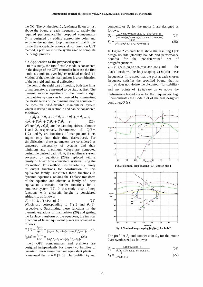
compensator for the motor 1 are designed as follows:
. .⁄ ⁄ ⁄
⁄ ⁄ .⁄ ⁄ (24)
.
. . .⁄⁄ (25)
In Figure 2 colored lines show the resulting QFT design bounds (stability bounds and performance bounds) for the pre-determined set of designfrequencies
}800,400,200,100,80,50,10,5,2,1{ and the
black lineshows the loop shaping )( jL for these
frequencies. It is noted that the plot at each chosen frequency satisfies the specified bound, that is,
)( jL does not violate the U-contour (for stability)
and any points of )( jL are on or above the
performance bound curve for the frequencies. Fig. 3 demonstrates the Bode plot of the first designed controller, )(1 sG .
Fig. 3: Nominal loop-shaping [ ] for hub 1
Fig. 4 Nominal loop-shaping [ ] for hub 2
The prefilter and compensator for the motor 2 are synthesized as follows:
. .⁄
. . .⁄⁄ (26)
.⁄ (27)
International Journal of Robotics, Vol.3, No.1, (2013)/M. S. Mirshamsi, M. Mirshamsi
54
To control the elastic part of motion and suppress the undesired vibrations of flexible link, the third equation of (16) (elastic deflection equation) is treated in the same approach. The equation can be written as:
(28)
where , , … , and are functions of manipulator joints angles only (not their time derivatives) and can be considered as uncertainty. Again RS method is used. Desired output set is considered as:
(29) Which are corresponding to , and , respectively. Substituting (29) in (28) and getting the Laplace transform of equation, a transfer function from input voltage to output tip deflection is obtained as follows:
(30)
where represents a plant gain which is subject
to variation with respect to the hysteresis behavior of the piezoelectric actuator (refer to in equation (28)).Using this family of uncertain linear time-invariant equivalent plants, the prefilter and regulating compensator for the piezoelectric actuator is also designed by applying QFT.( )
.⁄ .⁄ .⁄
.⁄ .⁄ . ⁄⁄(31)
.
. . .⁄⁄ (32)
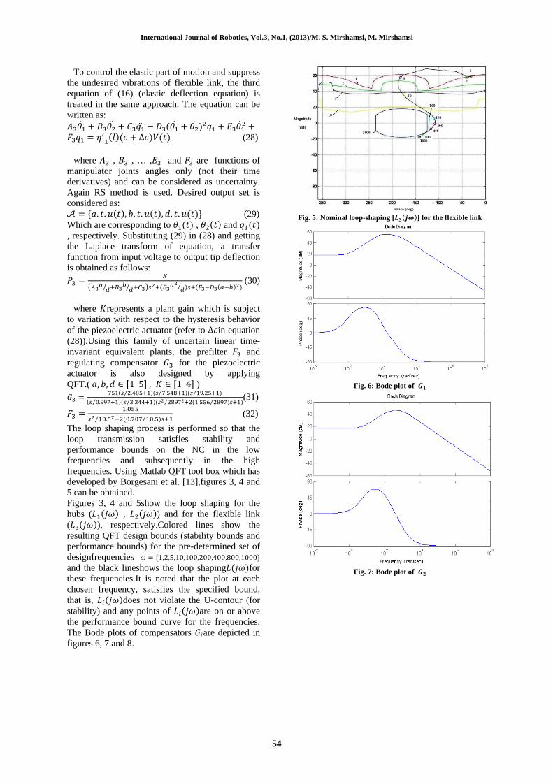
The loop shaping process is performed so that the loop transmission satisfies stability and performance bounds on the NC in the low frequencies and subsequently in the high frequencies. Using Matlab QFT tool box which has developed by Borgesani et al. [13],figures 3, 4 and 5 can be obtained. Figures 3, 4 and 5show the loop shaping for the hubs ( , ) and for the flexible link ( ), respectively.Colored lines show the resulting QFT design bounds (stability bounds and performance bounds) for the pre-determined set of designfrequencies
and the black lineshows the loop shaping for these frequencies.It is noted that the plot at each chosen frequency, satisfies the specified bound, that is, does not violate the U-contour (for stability) and any points of are on or above the performance bound curve for the frequencies. The Bode plots of compensators are depicted in figures 6, 7 and 8.
Fig. 5: Nominal loop-shaping [ ] for the flexible link
Fig. 6: Bode plot of
Fig. 7: Bode plot of

International Journal of Robotics, Vol.3, No.1, (2013)/M. S. Mirshamsi, M. Mirshamsi
55
Fig. 8 Bode plot of
4- Results and Discussion In order to demonstrate the superior control
performance of the proposed QFT control scheme, a numerical simulation is considered here. The physical parameters of the system are given in Table 1. Table.1:Parameters of the rigid–flexible manipulator system
and piezoelectric materials. ([7] ,[11]) Young’s modulus(Gpa)
Thickness(mm)
Density(kg/ )
Moment of inertia(kg
)
Length(m)
Link 1 Link 2 65 Piezoelectric 64
1.6 0.815
2890 7700
0.32
0.61 0.52 0.18
Moment of inertia of the hub( ) 0.02 Mass of the hub( ) 0.23 Capacitance of the piezofilm 380 pF Piezoelectric stress constant of the piezofilm
Piezoelectric strain constant of the piezoceramic
A circular path with radius was
considered as the desired trajectory. The end point of manipulator should follow it in 6.2 seconds. Desired joint angles are obtained by using inverse kinematics solution of the two-rigid-link manipulator. Also desired input for elastic deflection is considered as zero. It is clear from figure 9(a) that the imposed desired angular displacements are accurately achieved and settled within the specified time notwithstanding the oscillating disturbance of the flexible link. However, the application of these control torques to the links causes undesirable vibration of flexible link. Figure 9(b) presents measured tracking responses with feedback control voltage. It is obvious from figure 9(b) that using the piezoelectric actuator, the undesirable oscillation of the flexible link is quickly reduced, yielding the
Desired tip position. The tip deflection decreases more than 20 times compared with condition without applying control voltage to piezoelectric actuator. Figures 6, 7 and 8 show that the designed controllers are realizable because their bandwidths are limited.
(a)Without control voltage
(b)With control voltage Fig. 9: Simulated tracking responses
0 1 2 3 4 5 6-0.5
0
0.5
Pos
ition
of j
oint
1(rad
)
0 1 2 3 4 5 6
0
1
2
3
Pos
ition
of j
oint
2(rad
)
0 1 2 3 4 5 6-0.1
-0.05
0
0.05
0.1
Time(sec)Tip
def
lect
ion(
m)
actual
desired
actual
desired
0 1 2 3 4 5 6-0.5
0
0.5
Pos
ition
of
join
t 1(
rad)
0 1 2 3 4 5 6
0
1
2
3
Pos
ition
of
join
t 2(
rad)
0 1 2 3 4 5 6-0.1
-0.05
0
0.05
0.1
Time(sec)
Tip
def
lect
ion(
m)
actual
desired
actual
desired

International Journal of Robotics, Vol.3, No.1, (2013)/M. S. Mirshamsi, M. Mirshamsi
56
(a)Without control voltage
(b)With control voltage
Fig. 10:Simulatedend point position of manipulator
4- Conclusions A robust position control of a two-link rigid–flexible manipulator system which features piezoelectric actuator and sensor was achieved by applying the QFT technique together with RS method which is a simple method for replacing the nonlinear system by a family of uncertain linear systems. Results showed the good performance of the proposed controllers in reduction of residual vibration of elastic link and tracking the circular trajectory by the manipulator end point. Also, the simulation results showed that the third controller and applying control voltage to piezoelectric patch cause quick damping of elastic link vibrations and greatly reduce the flexible link tip deflection. Also the bandwidth of all designed controllers was limit and this implied that these controllers are realizable. References [1] S. Choura and A. S. Yigit, Control of a two-
link rigid-flexible manipulator with a moving payload mass , Journal of Sound and vibration, vol. 243, pp. 883-897, 2001.
[2] T. W. Yang, W. L. Xu, and S. K. Tso, Dynamic modeling based on real-time reflection measurement and compensation control for flexible multi-link manipulators , Journal of Dynamics and Control,vol. 11, pp. 5-24, 2001.
[3] S. K. Ider, M. K. Ozgoren, and V. Ay, Trajectory tracking control of robots with flexible links , Journal of Mechanism and Machine Theory, vol. 37, pp. 1377-1394, 2002.
[4] Z. X. Shi, H. K. Fung, and Y. C. Li, Dynamic modeling of rigid-flexible manipulator for constrained motion task control , Journal of Applied Mathematical Modeling, vol. 23, pp. 509-525, 1999.
[5] N. C. Park, H. S. Yang, H. W. Park, and Y. P. Park, Position/vibration control of two-degree-of-freedom arms having one flexible link with artificial pneumatic muscle actuators , Journal of Robotics and Autonomous Systems, vol. 40, pp. 239-253, 2002.
[6] R. J. Theodore, and A. Ghosl, Robust control of multilink flexible manipulators , Journal of Mechanism and Machine Theory, vol. 38, pp. 367-377, 2003.
[7] L. Tian, and C. Collins, A dynamic recurrent neural network-based controller for a rigid-flexible manipulator system , Journal of Mechateronics, vol. 14, pp. 471-490, 2004.
[8] B. Subudhi, and A.S. Morris, Soft computing methods applied to the control of a flexible robot manipulator , Journal of Applied Soft Computing,vol. 9, pp. 149-158, 2009.
[9] A. N. Irani, and H. A. Talebi, Tip tracking of a rigid-flexible manipulator based on deflection estimation using neural network observer: A backstepping approach , in IECON 2011 - 37th Annual Conference on IEEE Industrial Electronics Society, 2011, pp. 313 - 318.
[10] O. Yaniv, Quantitative feedback design of linear and nonlinear control systems,Massachusetts, USA: Kluwer Academic Publishers, 1999.
[11] S. B. Choi, S. S. Cho, H. C. Shin, and H. K. Kim, Quantitative feedback theory control of single-link flexible manipulator featuring piezoelectric actuator and sensor , Journal of Smart Materials Structures,vol. 8, pp. 338-349, 1999.
[12] M. Sobhani, and M. Rafeeyan, Robust controller design for multivariable nonlinear uncertain systems , Iranian Journal of Science & Technology, vol. 24, pp. 345-356, 2000.
[13] C. Borgesani, Y. Chait, O. Yaniv, TheQFT frequency Domain Control Design Toolbox for Use with MATLAB, Terasoft Inc., 2003.
0 0.2 0.4 0.6 0.8 1 1.2-0.2
0
0.2
0.4
0.6
0.8
X(m)
Y(m
)
desired
actual
0 0.2 0.4 0.6 0.8 1 1.2-0.2
0
0.2
0.4
0.6
0.8
X(m)
Y(m
)
desired
actual