q:acadfiledakota homescarladh carla 000-ts …buildwithdakota.com/images/homeimages/carla full...
TRANSCRIPT


SCENIC DRIVE

SCALE: 1/4" = 1'-0" BASEMENT FLOOR PLAN

SCALE: 1/4" = 1'-0" MAIN FLOOR PLAN
XX SEE SHEETS S4 AND S5 FORALL STRUCTURAL DETAILS
MARK HOLD-DOWN 1,3 ANCHOR POST
A STHD8 STRAP 8" EMBED. (2) 2X POST
C STHD14 STRAP 14" EMBED. (2) 2X POST
1. SIMPSON STRONG-TIE OR EQUIVALENT. STHD STRAPS USE "RJ" TYPE AT RIM JOIST LOCATIONS.2. 10d NAILS SHALL BE COMMON NAILS. SHEAR WALL EDGE NAILING SHALL BE TO POST.3. MISPLACED STHD HOLD-DOWNS MAY BE RETROFITTED USING HTT22 HOLD-DOWNS WITH 5/8" ALL- THREAD BOLTS. EPOXY INTO FOUNDATION WALL WITH 5 INCHES EMBEDMENT. WHERE FRAMED WALL IS FLUSH WITH FOUNDATION WALL USE MST48 WITH TWO 1/2" DIA. WEDGE ANCHORS AS OPTION. FASTEN WITH 16-16d COMMON NAILS TO POST ABOVE.
(24) 10d
(38) 10d
HOLD-DOWN SCHEDULEFASTENERS 2
SOLE PLATE 4 SILL PLATE 5
SW1 7/16" 8d @ 6" 2" NOMINAL 10d @ 12" 1/2" A.B. @ 32"
SW2 7/16" 8d @ 4" 2" NOMINAL 10d @ 12" 1/2" A.B. @ 32"
1. WOOD STRUCTURAL PANELS--SHEATHING.2. COMMON OR BOX NAILS. FIELD NAILING 12".3. ANCHOR BOLTS SHALL HAVE A 3x3x0.229" WASHER AND 7" MIN EMBEDDMENT.
MARKWALL
FRAMING 3,6EDGE
NAILING 2SHEATHING 1
SHEAR WALL SCHEDULEANCHORAGE
THESE STRUCTURAL DRAWINGSARE BASED ON ARCHITECTURALDRAWINGS. SEE CURRENT ISSUE ORREVISION DATE.
DIMENSIONS AND ELEVATIONS ARESUPPLIED BY THE ARCHITECT. THEYMAY BE PROVIDED ON THESTRUCTURAL PLANS AND DETAILSFOR THE CONVENIENCE OF THECONTRACTOR. VERIFY DIMENSIONSAND ELEVATIONS WITHARCHITECTURAL DRAWINGS.
801.224.0050801.229.9020
1429 South State St.Orem, Utah 84097
PhoneFax
SW1
A
SW
1
A
SW2
A A
SW2A A
C C C
SW
1
C
SW1
AA


SCALE: 1/4" = 1'-0" ROOF PLAN


FW9FT22
FW9FT20
FT18
FT18
FT18
FT18
FT18
FW9
FT20
FW9 FT20
FW9 FT20
FT18
FW9 FT20
FW2 FT20
FW9
FT20
FW9 FT20
FW2
FT20
FW9
FT20
FW9 FT22
SCALE: 1/4" = 1'-0"
FOOTING & FOUNDATION PLAN
PROVIDE SHORING
USE 22 GAGE STEEL
FW2
FT20
FT18
FT18
SF2
0
MARK WIDTH 1 LENGTH THICKNESS TRANSVERSE LENGTHWISE
FT18 18 " CONT. 10 " - (2) #4
FT20 20 " CONT. 10 " - (2) #4
FT22 22 " CONT. 10 " - (2) #4
SF20 20 " 20 " 10 " (2) #4 (2) #4
1. CONTINUOUS FOOTINGS SHALL BE CENTERED UNDER WALLS AND SPOT FOOTINGS SHALL BE CENTERED UNDER COLUMNS UNLESS NOTED OTHERWISE.
REINFORCEMENTFOOTING SCHEDULE
MARK HEIGHT WIDTH VERTICAL HORIZONTAL PLACEMENT
FW2 2.5' 8" #4 @ 24" (2) #4 CENTER
FW9 9' 8" #4 @ 16" (7) #4 CENTER
1. DOWEL VERTICAL BARS INTO FOOTING.2. PLACE TOP AND BOTTOM BARS WITHIN 4" OF TOP AND BOTTOM OF WALL.3. PLACE REINFORCEMENT IN CENTER OF WALL OR NEAR EACH FACE, AS NOTED.
REINFORCEMENT 1,2,3FOUNDATION WALL SCHEDULE
THESE STRUCTURAL DRAWINGSARE BASED ON ARCHITECTURALDRAWINGS. SEE CURRENT ISSUE ORREVISION DATE.
DIMENSIONS AND ELEVATIONS ARESUPPLIED BY THE ARCHITECT. THEYMAY BE PROVIDED ON THESTRUCTURAL PLANS AND DETAILSFOR THE CONVENIENCE OF THECONTRACTOR. VERIFY DIMENSIONSAND ELEVATIONS WITHARCHITECTURAL DRAWINGS.
801.224.0050801.229.9020
1429 South State St.Orem, Utah 84097
PhoneFax
XX SEE SHEETS S4 AND S5 FORALL STRUCTURAL DETAILS

DO
UB
LE J
OIS
T
DO
UB
LE J
OIS
T
BEARING WALL
DO
UB
LE J
OIS
T
DO
UB
LE J
OIS
TSCALE: 1/4" = 1'-0"
MAIN FLOOR FRAMING PLAN
T 02
(2) TRIM
T 02(2) TRIM
T 02
(2) TRIM
T 02(2)
TRIM
FJ 01
P 03
(3) 2X POST
P 03(3)
2X P
OST
MB 04
T 02
(2) TRIM
MB
01
DO
UB
LE J
OIS
T
MARK TYPEP 02 (2)2X POSTP 03 (3)2X POSTP 04 (4)2X POSTP 06 4X6 POSTP 09 3.5X5.25 PSLT 02 (2)TRIM
1. PARALLEL STRAND LUMBER (PSL) 1.8E2. STEEL PIPE (PIPE STD) A533. STEEL HOLLOW SECTION (HSS) A5004. STEEL COLUMNS REQUIRE BEARING PLATES5. CONTINUE POSTS TO FDN / STRUCT MEMBER
POST SCHEDULE
TYPE THICKNESSFLOOR 3/4" (48/24 SPAN RATING)ROOF 7/16" (24/16 SPAN RATING)
1. SHEATHING PERPENDICULAR TO SUPPORTS.2. FLOOR SHEATHING NAILED & GLUED TO SUPPORT.3. 8d COMMON NAILS 6" O.C. (EDGES) 12" O.C. (FIELD)4. NAILING NO CLOSER THAN 3/8" FROM PANEL EDGE.
SHEATHING SCHEDULE
MARK TYPEFJ 01 11.875" TJI 210 @ 16" O.C.
1. DIMENSIONAL LUMBER DF#2 U.N.O.
FLOOR JOIST SCHEDULE
MB BEAM SCHEDULEMARK TYPEMB 01 (2)2X6MB 02 11.875" TJI 110MB 03 11.875" TJI 110MB 04 (2)1.75X9.5 LVL
1. DIMENSIONAL LUMBER DF#2 U.N.O.2. LAMINATED VENEER LUMBER (LVL) 1.9E3. GLUED-LAMINATED TIMBER (GLB) 24F-1.8E4. STEEL W-SHAPES A992-50
THESE STRUCTURAL DRAWINGSARE BASED ON ARCHITECTURALDRAWINGS. SEE CURRENT ISSUE ORREVISION DATE.
DIMENSIONS AND ELEVATIONS ARESUPPLIED BY THE ARCHITECT. THEYMAY BE PROVIDED ON THESTRUCTURAL PLANS AND DETAILSFOR THE CONVENIENCE OF THECONTRACTOR. VERIFY DIMENSIONSAND ELEVATIONS WITHARCHITECTURAL DRAWINGS.
801.224.0050801.229.9020
1429 South State St.Orem, Utah 84097
PhoneFax
XX SEE SHEETS S4 AND S5 FORALL STRUCTURAL DETAILS
MB 02MB
03
MB 01
MB 01
P 02
(2) 2X
POST
MB 01

SCALE: 1/4" = 1'-0"
ROOF FRAMING PLAN
P 02
(2) 2X POST
RB 01
P 02(2)
2X P
OST
RB 01
RB 01
RB 02
P 06
4X6 P
OST
P 04(4) 2X POST
RB 06 RB 05
T 02
(2) TRIM
T 02(2) TRIM
P 02
(2) 2X POST
RB 01
P 02(2)
2X P
OST
RB 01
RB 01
RB 08
P 02(2)
2X P
OST
RB 01
RB 06
T 02(2)
TRIM
P 04(4) 2X POST
RB
09P 03(3) 2X POST
RB 06
P 02
(2) 2X POST
RB
07
P 02(2) 2X POST
P 02(2) 2X POST
RB
07
P 02
(2) 2X POST
RB 06
P 06
4X6 P
OST
P 02
(2) 2X POST
RB 01RB 01
P 09
3.5X5.25 PSL
MANUFACTURED TRUSSES @ 24" O.C.
P 04
(4) 2X
POST
MARK TYPEP 02 (2)2X POSTP 03 (3)2X POSTP 04 (4)2X POSTP 06 4X6 POSTP 09 3.5X5.25 PSLT 02 (2)TRIM
1. PARALLEL STRAND LUMBER (PSL) 1.8E2. STEEL PIPE (PIPE STD) A533. STEEL HOLLOW SECTION (HSS) A5004. STEEL COLUMNS REQUIRE BEARING PLATES5. CONTINUE POSTS TO FDN / STRUCT MEMBER
POST SCHEDULE
1. DESIGN SNOW LOADS SHALL BE IN ACCORDANCE WITH ASCE 7-05 CHAP.7 (2009 IBC 1608.1)
WOOD TRUSS LOADSGROUND SNOW LOAD, Pg = 44 PSFFLAT ROOF SNOW LOAD = 30 PSFTOP CHORD DEAD LOAD = 10 PSFBOTTOM CHORD DEAD LOAD = 5 PSF
TYPE THICKNESSFLOOR 3/4" (48/24 SPAN RATING)ROOF 7/16" (24/16 SPAN RATING)
1. SHEATHING PERPENDICULAR TO SUPPORTS.2. FLOOR SHEATHING NAILED & GLUED TO SUPPORT.3. 8d COMMON NAILS 6" O.C. (EDGES) 12" O.C. (FIELD)4. NAILING NO CLOSER THAN 3/8" FROM PANEL EDGE.
SHEATHING SCHEDULE
RB BEAM SCHEDULEMARK TYPERB 01 (2)2X6RB 02 (2)2X8RB 03 (2)1.75X9.5 LVLRB 04 (2)1.75X11.875 LVLRB 05 (2)1.75X9.5 LVLRB 06 (2)2X6RB 07 (2)2X8RB 08 (2)1.75X9.5 LVLRB 09 (2)2X10
1. DIMENSIONAL LUMBER DF#2 U.N.O.2. LAMINATED VENEER LUMBER (LVL) 1.9E3. GLUED-LAMINATED TIMBER (GLB) 24F-1.8E4. STEEL W-SHAPES A992-50
THESE STRUCTURAL DRAWINGSARE BASED ON ARCHITECTURALDRAWINGS. SEE CURRENT ISSUE ORREVISION DATE.
DIMENSIONS AND ELEVATIONS ARESUPPLIED BY THE ARCHITECT. THEYMAY BE PROVIDED ON THESTRUCTURAL PLANS AND DETAILSFOR THE CONVENIENCE OF THECONTRACTOR. VERIFY DIMENSIONSAND ELEVATIONS WITHARCHITECTURAL DRAWINGS.
801.224.0050801.229.9020
1429 South State St.Orem, Utah 84097
PhoneFax
XX SEE SHEETS S4 AND S5 FORALL STRUCTURAL DETAILS
T 02
(2) TRIM
T 02
(2) TRIM
RB 03
BEAR TRUSSES HERE
P 03
(3) 2X POST
RB
01R
B 01
RB 04
RB
01
P 02(2) 2X POST
NO SCALE
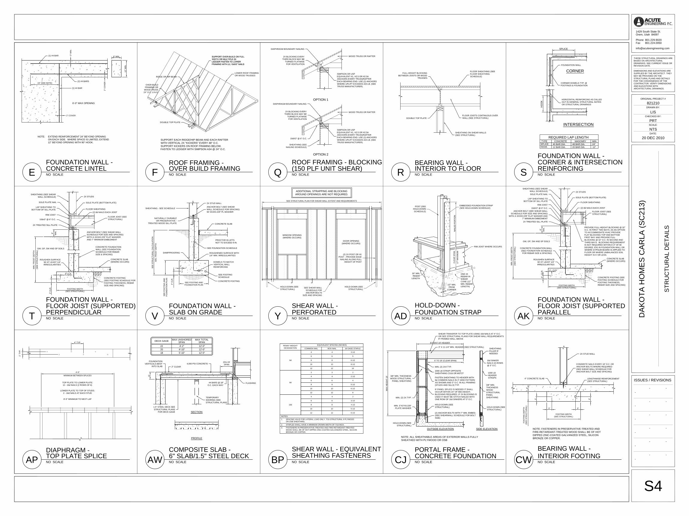
FOUNDATION WALL -
NOTE: EXTEND REINFORCEMENT 24" BEYOND OPENINGON EACH SIDE. WHERE SPACE IS LIMITED, EXTEND12" BEYOND OPENING WITH 90° HOOK.
6'-0" MAX OPENING
24" (SEE NOTE)
CONCRETE LINTELE
(1) #4 BAR
(2) #4 BARS
2" COVER
2" C
OVE
R
8" MIN.
12" M
IN.
3" M
IN.
(1) #4 BAR
NO SCALEOVER BUILD FRAMING
SUPPORT EACH RIDGE/HIP BEAM AND EACH RAFTERWITH VERTICAL 2X "KICKERS" EVERY 48" O.C.SUPPORT KICKERS ON ROOF FRAMING BELOW.FASTEN TO LEDGER WITH SIMPSON A34 @ 24" O.C.
ROOF FRAMING -F
LOWER ROOF FRAMINGOR WOOD TRUSSESRIDGE OR HIP BEAM
OVER-BUILDFRAMING OR
WOOD TRUSS24" O.C. U.N.O.
DOUBLE TOP PLATE
NO SCALE
OPTION 1
OPTION 2
(150 PLF UNIT SHEAR)ROOF FRAMING - BLOCKING
Q
SIMPSON OR USPEQUIVALENT H1, H2.5 OR H2.5AANCHORS EVERY TRUSS/RAFTEREACH BEARING END. USE (2) ANCHORSWHERE UPLIFT EXCEEDS 415 LB. (SEETRUSS MANUFACTURER).
WOOD TRUSS OR RAFTER
SIMPSON OR USPEQUIVALENT H1, H2.5 OR H2.5AANCHORS EVERY TRUSS/RAFTEREACH BEARING END. USE (2) ANCHORSWHERE UPLIFT EXCEEDS 415 LB. (SEETRUSS MANUFACTURER).
WOOD TRUSS OR RAFTER
SHEATHING (SEENAILING SCHEDULE)
10dX3" @ 6" O.C.
DIAPHRAGM BOUNDARY NAILING
2X BLOCKING EVERYTHIRD BLOCK MAY BE
TURNED FLATWISEFOR VENTILATION
DIAPHRAGM BOUNDARY NAILING
2X BLOCKING EVERYTHIRD BLOCK MAY BE
TURNED FLATWISEFOR VENTILATION
NO SCALE
FLOOR SHEATHING (SEEFLOOR SHEATHINGSCHEDULE)
FLOOR JOISTS CONTINUOUS OVERWALL (SEE STRUCTURAL)
SHEATHING ON SHEAR WALLS(SEE STRUCTURAL)
FULL-HEIGHT BLOCKINGBETWEEN JOISTS OR WOOD
TRUSSES
DOUBLE TOP PLATE
INTERIOR TO FLOORBEARING WALL -
R NO SCALE
FOUNDATION WALL
CORNER DOWELS TYP. @FOOTINGS & FOUNDATION
CORNER
INTERSECTION
REQUIRED LAP LENGTHCONCRETE
12 BAR DIA.40 BAR DIA.
HORIZONTAL REINFORCING AS CALLEDOUT IN GENERAL STRUCTURAL NOTESOR STRUCTURAL DRAWINGS
HOOK
TYPESPLICE
HO
OK
12"24"
MASONRY
20 BAR DIA.48 BAR DIA.
MIN.
SPLICE
CORNER & INTERSECTIONFOUNDATION WALL -
REINFORCINGS
NO SCALEPERPENDICULARFLOOR JOIST (SUPPORTED)FOUNDATION WALL -
T
FOOTING WIDTH(SEE STRUCTURAL)
FLOOR SHEATHING
RIM JOIST
ROUGHEN SURFACEW/ AT LEAST 1/4"IRREGULARITIES
FLOOR JOIST (SEESTRUCTURAL)
2X STUDS
SOLE PLATE (BOTTOM PLATE)
GW, GP, SW AND SP SOILS
(2) 8d NAILS EACH JOIST
MIN
. FR
OS
T D
EPT
H
(SE
E ST
RU
CTU
RAL
)
10dx3" @ 6" O.C.
2X TREATED SILL PLATE
LAP SHEATHING TOBOTTOM OF SILL PLATE
SOLE PLATE NAIL
SHEATHING (SEE SHEARWALL SCHEDULE)
ANCHOR BOLT (SEE SHEAR WALLSCHEDULE FOR SIZE AND SPACING)WITH A 3X3X0.229" FLAT WASHERAND 7" MINIMUM EMBEDMENT
CONCRETE FOUNDATIONWALL (SEE FOUNDATIONSCHEDULE FOR REBARSIZE & SPACING)
CONCRETE SLAB(WHERE OCCURS)
CONCRETE FOOTING(SEE FOOTING SCHEDULE FORFOOTING THICKNESS, REBARSIZE AND SPACING)
3" C
LR.
3" CLR.
6" MIN
.
NO SCALESLAB ON GRADE
SEE FOOTING ANDFOUNDATION PLAN
SEE
STR
UC
TUR
AL
CA
LCU
LATI
ON
MIN
. FR
OS
T D
EPT
H
SE
E F
OO
TIN
G A
ND
FOU
ND
ATIO
N P
LAN
3" C
LR.
3"
FOUNDATION WALL -
V
2X STUD WALL
ANCHOR BOLT (SEE SHEARWALL SCHEDULE FOR SPACING)W/ 3X3X0.229" PL WASHER
CONCRETE SLAB
PROCTOR IN LIFTSNOT TO EXCEED 9 IN.
SEE FOUNDATION SCHEDULE
ROUGHENED SURFACE WITH1/4" MIN. IRREGULARITIES
DOWELS TO MATCHVERTICAL WALLREINFORCING
SEE FOOTINGSCHEDULE
CONCRETE FOOTING
SHEATHING - SEE SCHEDULE
NATURALLY DURABLEOR PRESERVATIVE -
TREATED WOOD SILL PLATE
DAMPPROOFING
NO SCALEPERFORATED
SEE STRUCTURAL PLAN FOR SHEAR WALL EXTENT AND REQUIREMENTS
SHEAR WALL -
Y
HOLD-DOWN (SEESTRUCTURAL)
SEE SHEAR WALLSCHEDULE FORANCHOR BOLTS
SIZE AND SPACING
HOLD-DOWN (SEESTRUCTURAL)
ADDITIONAL STRAPPING AND BLOCKINGAROUND OPENINGS ARE NOT REQUIRED.
WINDOW OPENING(WHERE OCCURS)
DOOR OPENING(WHERE OCCURS)
(2) 2X POST OR 4XPOST - PROVIDE EDGE
NAILING ALONG FULLHEIGHT OF POST
NO SCALEAD FOUNDATION STRAPHOLD-DOWN -
POST (SEEHOLD-DOWNSCHEDULE)
EMBEDDED FOUNDATION STRAP(SEE HOLD-DOWN SCHEDULE)
RIM JOIST WHERE OCCURS
CLE
AR
SPA
N
17" M
AXIM
UM
NA
ILE
D P
OR
TIO
N
30" MIN.REBAR
LENGTH
ONE #4REBAR INSHEARCONE (12"MIN. REBARLENGTH)
1/2" MIN.FROM
CORNER
NO SCALEAK PARALLELFLOOR JOIST (SUPPORTED
GW, GP, SW AND SP SOILS
FOUNDATION WALL -
MIN
. FR
OS
T D
EPT
H
(SE
E ST
RU
CTU
RAL
)
6" MIN
.C
LR. CLR.
3"
3"
FOOTING WIDTH(SEE STRUCTURAL)
2X STUDS
SOLE PLATE (BOTTOM PLATE)
FLOOR SHEATHING
(2) 8d NAILS EACH JOIST
FLOOR JOIST (SEESTRUCTURAL)
PROVIDE FULL-HEIGHT BLOCKING @ 32"O.C. IN FIRST TWO BAYS. AS AN OPTIONTO ACCOMMODATE HVAC PROVIDEFLAT BLOCKING TOP AND BOTTOMFIRST BAY AND PROVIDE FULLBLOCKING @ 32" O.C. IN SECOND ANDTHIRD BAYS. BLOCKING REQUIREMENTIS NOT REQUIRED WITHIN 6'-0" OF 90DEGREE JOG IN FOUNDATION WALL ORWHERE GYPSUM BOARD IS APPLIED TOFLOOR OR WHERE UNBALANCED SOILHEIGHT IS 5' OR LESS.
CONCRETE SLAB(WHERE OCCURS)
CONCRETE FOOTING (SEEFOOTING SCHEDULE FORFOOTING THICKNESS,REBAR SIZE AND SPACING)
ROUGHEN SURFACEW/ AT LEAST 1/4"IRREGULARITIES
SHEATHING (SEE SHEARWALL SCHEDULE)SOLE PLATE NAIL
LAP SHEATHING TOBOTTOM OF SILL PLATE
RIM JOIST10dX3" @ 6" O.C.
ANCHOR BOLT (SEE SHEAR WALLSCHEDULE FOR SIZE AND SPACING)
WITH A 3X3X0.229" FLAT WASHER AND7" MINIMUM EMBEDMENT2X TREATED SILL PLATE
CONCRETE FOUNDATION WALL(SEE FOUNDATION SCHEDULEFOR REBAR SIZE & SPACING)
AP NO SCALETOP PLATE SPLICEDIAPHRAGM -
4'-0"
MINIMUM BETWEEN SPLICES
TOP PLATE TO LOWER PLATE:12 - 16d NAILS (2 ROWS OF 6)
LOWER PLATE TO TOP OF STUDS:2 - 16d NAILS AT EACH STUD
8'-0" MINIMUM TO NEXT LAP
4" TYP.
1" T
YP.
NO SCALEAW 6" SLAB/1.5" STEEL DECK
PROFILE
SECTION
25% OFSPAN
6"
COMPOSITE SLAB -
22
DECK GAGE MAX UNSHOREDSPAN
2018
4'-2"4'-10"5'-10"
FOUNDATIONVERTICALS BENT
INTO SLAB4,000 PSI CONCRETE
2" CLEAR
1.5" STEEL DECK SEESTRUCTURAL PLANS
FOR DECK GAGE
#4 BARS @ 18"O.C. EACH WAY
TEMPORARYSHORING (SEESTRUCTURAL PLANS
FLASHING
MAX TOTALSPAN12'-0"12'-0"12'-0"
BP NO SCALE
1.
2.
NOTES:
PENNY WEIGHTDESIGNATION BOX NAIL
EQUIVALENT SPACING (INCHES)
16 GAGE STAPLECOMMON NAIL
6d
8d
10d
4
6
8
10
12
4
6
8
10
12
3 1/2
5
6 1/2
8 1/2
10
3
4
6
8
10
12
3
4
6
8
10
12
4
6
8
10
12
4
6
8
10
12
2
3 1/2
4 1/2
5 1/2
6 1/2
2
2 1/2
4
5 1/2
6 1/2
8
SPACING VALID FOR LATERAL LOAD ONLY, 7/16 STRUCTURAL II PLYWOODOR OSB SHEATHING.
STAPLES SHALL HAVE A MINIMUM CROWN WIDTH OF 7/16 INCH.
SHEATHING FASTENERSSHEAR WALL - EQUIVALENT
3. FASTENERS IN PRESERVATIVE-TREATED AND FIRE-RETARDANT-TREATED WOOD SHALL BE OF HOT DIPPED ZINC-COATED GALVANIZED STEEL, SILICONBRONZE OR COPPER.
EXTENT OF HEADER
MA
X H
EIG
HT
10'
CJ NO SCALECONCRETE FOUNDATIONPORTAL FRAME -
NOTE: ALL SHEATHABLE AREAS OF EXTERIOR WALLS FULLYSHEATHED WITH PLYWOOD OR OSB
SIDE ELEVATIONOUTSIDE ELEVATION
16d SINKERNAILS (2) ROWS@ 3" O.C.
1000 LBHEADERSTRAPS
3/8" MIN.THICKNESSWOODSTRUCTURALPANELSHEATHING
HOLD-DOWN (SEESTRUCTURAL)
SHEATHINGFILLER IFNEEDED
6' TO 18' (CLEAR SPAN)
MIN. (2) 2X4 TYP.
1000 LB STRAP OPPOSITESHEATHING CS16 OR MST27
FASTEN SHEATHING TO HEADER WITH8d COMMON NAILS IN 3" GRID PATTERNAS SHOWN AND 3" O.C. IN ALL FRAMING(STUDS AND SILLS) TYP.
IF PANEL SPLICE IS NEEDED IT SHALLOCCUR WITHIN 24" OF MID-HEIGHT,BLOCKING REQUIRED. IF 2X BLOCKING ISUSED IT MUST BE STITCH NAILED WITHONE ROW OF 16d SINKERS AT 3" O.C.
HOLD-DOWN (SEESTRUCTURAL)
MIN. (2) 2X TYP.
3/8" MIN. THICKNESSWOOD STRUCTURAL
PANEL SHEATHING
MIN. 3"X3"X0.229"PLATE WASHER
(2) ANCHOR BOLTS WITH 7" MIN. EMBED.(SEE SHEARWALL SCHEDULE FOR BOLTSIZE)
HOLD-DOWN (SEESTRUCTURAL)
SHEAR TRANSFER TO TOP PLATE USING 10d NAILS AT 4" O.C.OR SEE STRUCTURAL PLANS FOR SHEAR WALL REQUIREMENTSIF FRAMED WALL ABOVE
3" X 11-1/4" MIN. HEADER (SEE STRUCTURAL)
CW NO SCALEINTERIOR FOOTINGBEARING WALL -
FOO
TIN
G D
EPTH
(SE
E ST
RU
CTU
RAL
)4"
FOOTING WIDTH(SEE STRUCTURAL)
3"
3"
3"
3"
NOTE: FASTENERS IN PRESERVATIVE-TREATED ANDFIRE-RETARDANT-TREATED WOOD SHALL BE OF HOTDIPPED ZINC-COATED GALVANIZED STEEL, SILICONBRONZE OR COPPER.
LENGTHWISE REINFORCEMENT(SEE STRUCTURAL)
CONSRETE NAILS EVERY 16" O.C. ORANCHOR BOLTS WHERE REQUIRED(SEE SHEAR WALL SCHEDULE FORANCHOR BOLT SIZE AND SPACING)
2X STUD WALL
4" CONCRETE SLAB
801.224.0050801.229.9020
1429 South State St.Orem, Utah 84097
PhoneFax
ORIGINAL PROJECT #
DRAWN BY:
CHECKED BY:
SCALE:
DATE:
THESE STRUCTURAL DRAWINGS AREBASED ON ARCHITECTURALDRAWINGS. SEE CURRENT ISSUE ORREVISION DATE.
DIMENSIONS AND ELEVATIONS ARESUPPLIED BY THE ARCHITECT. THEYMAY BE PROVIDED ON THESTRUCTURAL PLANS AND DETAILSFOR THE CONVENIENCE OF THECONTRACTOR. VERIFY DIMENSIONSAND ELEVATIONS WITHARCHITECTURAL DRAWINGS.
ISSUES / REVISIONS
S4
STR
UC
TUR
AL
DE
TAIL
S
NTS
20 DEC 2010
821210
DA
KO
TA H
OM
ES
CA
RLA
(SC
213)
--
-
--
-
--
--
PRT
LIS
-
-
-
-
---
-
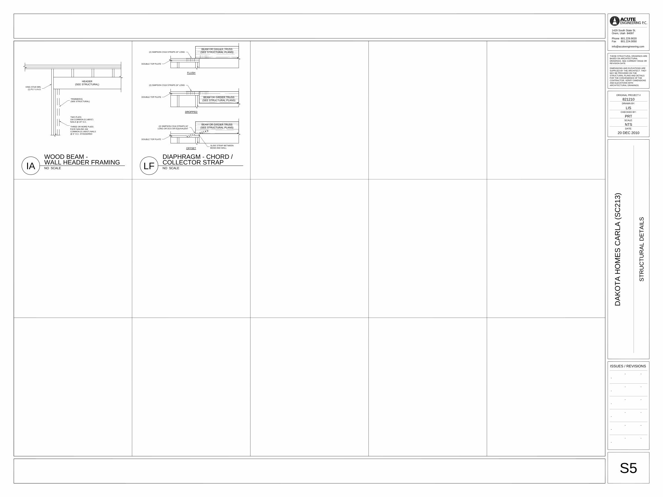
IA NO SCALEWALL HEADER FRAMING
HEADER(SEE STRUCTURAL)
WOOD BEAM -
TWO PLIES:10d COMMON (0.148X3")NAILS @ 24" O.C.
THREE OR MORE PLIES:FACE NAILING 10dCOMMON (0.148X3") NAILS@ 6" O.C. STAGGERED
KING STUD MIN.(1) PLY U.N.O.
TRIMMER(S)(SEE STRUCTURAL)
LF NO SCALECOLLECTOR STRAP
BEAM OR GIRDER TRUSS(SEE STRUCTURAL PLANS)
BEAM OR GIRDER TRUSS(SEE STRUCTURAL PLANS)
BEAM OR GIRDER TRUSS(SEE STRUCTURAL PLANS)
DIAPHRAGM - CHORD /
FLUSH
DROPPED
OFFSET
DOUBLE TOP PLATE
DOUBLE TOP PLATE
DOUBLE TOP PLATE
(2) SIMPSON CS16 STRAPS 24" LONG
(2) SIMPSON CS16 STRAPS 24" LONG
(2) SIMPSON CS16 STRAPS 24"LONG OR DCS OR EQUIVALENT
SLIDE STRAP BETWEENBEAM AND WALL
801.224.0050801.229.9020
1429 South State St.Orem, Utah 84097
PhoneFax
ORIGINAL PROJECT #
DRAWN BY:
CHECKED BY:
SCALE:
DATE:
THESE STRUCTURAL DRAWINGS AREBASED ON ARCHITECTURALDRAWINGS. SEE CURRENT ISSUE ORREVISION DATE.
DIMENSIONS AND ELEVATIONS ARESUPPLIED BY THE ARCHITECT. THEYMAY BE PROVIDED ON THESTRUCTURAL PLANS AND DETAILSFOR THE CONVENIENCE OF THECONTRACTOR. VERIFY DIMENSIONSAND ELEVATIONS WITHARCHITECTURAL DRAWINGS.
ISSUES / REVISIONS
S5
STR
UC
TUR
AL
DE
TAIL
S
NTS
20 DEC 2010
821210
DA
KO
TA H
OM
ES
CA
RLA
(SC
213)
--
-
--
-
--
--
PRT
LIS
-
-
-
-
---
-

DESIGN CRITERIA1. Building code: Utah State Construction Code 1.1 Model building code: 2009 IRC 1.2 Use and occupancy classification: R-3 (Residential - 1-unit dwelling) 1.3 Category: II (Not occupancy categories I, III, IV)2. Dead loads 2.1 Roof = 15 psf (10 psf top chord, 5 psf bottom chord) 2.2 Floor = 10 psf 2.3 Walls = 10 psf (interior walls), 11 psf (exterior walls)3. Live loads -- Roofs (ordinary construction) = 20 psf (or 300 lb point load) -- Residential (1-2 unit dwelling) = 40 psf -- Stairs and exits (residential 1-2 unit dwelling) = 40 psf -- Decks (residential 1-2 unit dwelling in Utah) = 60 psf4. Snow load 4.1 Ground snow load, Pg = 44 psf (elevation 4677 ft) 4.2 Exposure factor, Ce = 1 4.3 Thermal factor, Ct = 1 4.4 Occupancy importance factor, Is = 1 4.5 Flat roof snow load, Pf = 30 psf5. Earthquake design data 5.1 Mapped acceleration parameters 5.1.1 Latitude, Longitude: 40.534, -111.992 5.1.2 MCE short period Ss = 1.07 SDS = 0.76 5.1.3 MCE 1.0 sec. period S1 = 0.42 SD1 = 0.44 5.2 Seismic design category: D1 5.3 Occupancy importance factor, Ie = 1 5.4 Basic structural system: Bearing wall systems 5.5 Seismic force-resisting system: Light-frame walls (wood or steel sheathing) 5.5.1 Response modification factor R = 6.5 5.5.2 System overstrength factor Omega = 3 5.5.3 Deflection amplification factor Cd = 4 5.5 Equivalent Lateral Force Procedure 5.5.1 Seismic response coefficient Cs = 0.12 5.5.2 Seismic base shear (LRFD) V = 64516. Wind design data 6.1 Exposure category: C 6.2 Basic wind speed, V = 90 mph 6.3 Occupancy importance factor, Iw = 1 6.4 Internal pressure coeff., Gcpi = 0.187. Geotechnical design basis: - Presumptive values, 2009 IBC Table 1806.2 7.2 Site class = D 7.3 Soil notes: None 7.4 Lateral earth pressure 7.4.1 Active = 30 psf 7.4.2 At-rest = 60 psf 7.5 Allowable foundation parameters 7.5.1 Allowable soil bearing, Qa = 1500 psf 7.5.2 Allowable lateral bearing = 150 psf 7.5.3 Coefficient of friction = 0.25 7.6 Minimum frost cover = 30 in.
DEFERRED SUBMITTALS1. The following items are to submitted subsequent to the time of application (deferred submittals): -- Prefabricated metal plate wood trusses - roof (truss manufacturer)2. Deferred submittals shall have the prior approval of the building official (2009 IBC 107.3.4.2).3. Deferred submittal documents shall be submitted to the registered design professional in responsible charge who shall review and forward them to the building official with a notation indicating that the documents have been reviewed and found to be in general conformance to the design of the building (2009 IBC 107.3.4.2).4. Deferred submittal items shall not be installed until the design and submittal documents have been approved by the building official (2009 IBC 107.3.4.2).
GENERAL STRUCTURAL NOTES
GENERAL1. Construction documents are valid for a single use at the project location and shall not be reused, copied, or reproduced
without written approval of the registered design professional in responsible charge.2. General notes and typical details are provided as a supplement to the construction documents and apply where specific
notes and details are not available. Specific notes and structural details shall take precedence over general notes andtypical details. Structural requirements shown in the framing plans and in structural details shall take precedence overstructural notes indicated in architectural sections.
3. Printed dimensions shall take precedence over scales shown on construction documents. The registered designprofessional in responsible charge does not warrant the accuracy of scaled dimensions.
4. Approval by the inspector does not imply approval by the registered design professional in responsible charge. Structuralspecifications that are unclear or ambiguous shall be referred to the registered design professional in responsible chargefor interpretation or clarification.
5. The registered design professional in responsible charge assumes no liability for the accuracy, completeness, or codecompliance of architectural, electrical, mechanical, drainage, or other non-structural specifications.
6. Omissions in and conflicts between the various elements of the construction documents shall be brought to the immediateattention of the registered design professional in responsible charge and shall be resolved by the same before proceedingwith any work involved.
7. Requests for substitutions shall be submitted in writing to the registered design professional in responsible charge and shallinclude the reasons for the request and any cost differentials. Substitutions are not allowed unless approved in writing bythe registered design professional in responsible charge.
8. The contractor shall become familiar with all portions of the construction documents and shall insure that all subcontractorsare familiar with those portions pertaining to their area of work. The contractor shall verify all site conditions, dimensions,elevations, coordinate all doors, windows, non-bearing interior and exterior walls, elevations, slopes, stairs, curbs, drains,recesses, depressions, railings, waterproofing, finishes, chamfer, kerfs, and so forth, and immediately notify the registereddesign professional in responsible charge regarding actual conditions which are not in agreement with the constructiondocuments.
9. The contractor is responsible for the method, means, and sequence of all structural erection except when specifically notedotherwise in the construction documents. The contractor shall provide temporary shoring and bracing, providing adequatevertical and lateral support during erection. Shoring and bracing shall remain in place until all permanent members areplaced and all final connections are completed.
10. The contractor is responsible for standard connections, unless noted otherwise. The contractor shall obtain additionalassistance from the registered design professional in responsible charge for non-standard connections.
POST-INSTALLED ANCHORS1. Epoxy adhesive anchoring systems:
1.1. Concrete: Hilti HIT-RE 500-SD (ICC ES ESR-2322) or Simpson SET-XP (ICC ES ESR-2508)1.2. Masonry (grouted): Hilti HIT-HY 150-MAX (ICC ES ESR-1967) or Simpson SET (ICC ES ESR-1772)1.3. Steel reinforcement and rods shall be embedded 10 bar diameters unless noted otherwise in the structural drawings
and details. Where 10 bar diameters exceeds the member thickness minus minimum cover, steel reinforcement shallbe embedded the member thickness minus minimum cover with a standard hook.
1.4. Embedded portions of steel reinforcement and rods shall be clean, straight, and free of mill scale, rust and othercoatings that impair the bond with the adhesive. Reinforcement must not be bent after installation (ICC ES ESR-2322).
2. Mechanical expansion anchors:2.1. Concrete: Hilti KWIK BOLT TZ (ICC ES ESR-1917)2.2. Masonry: Hilti KWIK BOLT 3 (ICC ES ESR-1385)2.3. Expansion anchors shall not be used in tensile load applications (e.g. hold-downs, moment frames).
3. Post-installed anchoring systems shall be installed according to the manufacture’s instructions. Hole cleaning method shallbe based on drilling method and borehole conditions and shall conform to the manufacture’s instructions.
SOIL AND FOUNDATIONS1. Geotechnical investigations shall conform to 2009 IBC 1803. Excavation, grading and fill shall conform to 2009 IBC 1804.
Footings and foundations shall be constructed in accordance with 2009 IBC 1807 through 1810.2. Where required, the owner shall submit a geotechnical investigation report to the building official in accordance with 2009
IBC 1803. The contractor shall inform the registered design professional in responsible charge if the soil conditions are notconsistent with the investigation report and the foundation design data.
3. Excavations for any purpose shall not remove lateral support from any footing or foundation without first underpinning orprotecting the footing or foundation against settlement or lateral translation (2009 IBC 1804.1).
4. Excavation outside the foundation shall be backfilled with soil that is free of organic material, construction debris, cobblesand boulders or with soil that is a controlled low-strength material (CLSM). The backfill shall be placed in lifts andcompacted, in a manner that does not damage the foundation or the waterproofing or dampproofing material (2009 IBC1804.2).
5. The ground immediately adjacent to the foundation shall have a 5-percent slope away from the building for a minimumdistance of 10 feet measured perpendicular to the face of the foundation wall. If physical obstructions or lot lines prohibit 10feet of horizontal distance, a 5-percent slope shall be provided to an approved alternative method of diverting water awayfrom the foundation. Impervious surfaces within 10 feet of the building foundation shall have a minimum 2-percent slope(2009 IBC 1804.3).
6. Footings and foundations shall be built on undisturbed soil, compacted fill material or CLSM. Compacted fill material andCLSM shall conform to 2009 IBC 1804.5 and 2009 IBC 1804.6, respectively (2009 IBC 1809.2).
7. The top surface of the footings shall be level. The bottom surface of footings is permitted to have a maximum 10-percentslope. Footings shall be stepped where it is necessary to change the elevation of the top surface of the footing or where thesurface of the ground has more than a 10-percent slope (2009 IBC 1809.3).
8. The minimum depth of footings below the undisturbed ground surface shall be 12 inches (2009 IBC 1809.4). Foundationwalls, piers and other permanent supports shall be extended below the frost line, except where otherwise protected fromfrost (2009 IBC 1809.5).
9. The placement of footings on or adjacent to 33-percent slopes and steeper shall conform to 2009 IBC 1808.7.10.Floors of basements shall be placed over base course not less than 4 inches in thickness and a drain shall be installed
around the foundation perimeter that consists of gravel or crushed stone containing not more than 10-percent material thatpasses through a No. 4 sieve (2009 IBC 1805.4.1).
11.Backfill shall not be placed against a foundation wall until the wall has sufficient strength and is anchored to the floor above,or is sufficiently braced to prevent damage by the backfill, except bracing is not required for walls supporting less than 4feet of unbalanced backfill (R404.1.7).
CONCRETE1. Concrete materials, quality control, and construction shall comply with 2009 IBC Chapter 19 and ACI 318-08.2. Compressive strength (minimum specified at 28 days)
2.1. Footings: 3,000 psi (2009 IBC Table 1808.8.1)2.2. Interior floor slabs on grade: 4,000 psi2.3. Exterior floor slabs on grade: 4,000 psi (2009 IBC Table 1904.3)2.4. Suspended slabs: 4,000 psi (2009 IBC Table 1904.3)2.5. Walls: 3,000 psi (2009 IBC Table 1904.3) for R-2, R-3 occupancies and appurtenances
4,000 psi (2009 IBC Table 1904.3) for other occupancies3. Materials
3.1. Cements (ASTM C 150). Concrete exposed to freezing and thawing or deicing chemicals shall conform to themaximum water-cementitious material ratios and minimum compressive strength requirements of ACI 318-08 Table4.3.1.
3.2. Aggregates (ASTM C 33): nominal maximum size of coarse aggregate shall not be larger than 1/5 the narrowestdimension between forms, nor 1/3 the depth of slabs, nor 3/4 the minimum clear spacing between reinforcing bars orwires, tendons, or ducts (ACI 318-08 3.3.2).
3.3. Water used in mixing concrete shall be potable, clean and free from injurious amounts of oils, acids, alkalis, salts,organic materials, or other substances deleterious to concrete or reinforcement (ACI 318-08 3.4.1-2).
3.4. Admixtures shall be subject to prior approval by the registered design professional in responsible charge (ACI 318-083.6.3).
3.5. Concrete exposed to freezing and thawing or deicing chemicals shall be air-entrained with air content indicated in ACI318-08 Table 4.4.1. Tolerance on air content as delivered shall be plus/minus 1.5 percent (ACI 318-08 4.4.1).
4. Steel Reinforcement4.1. Deformed bars: fy = 60 ksi (ASTM A615)4.2. Welded plain wire: fy = 60 ksi (ASTM A185)4.3. Deformed Bar Anchors (DBA) (ASTM A496)4.4. Headed Stud Anchors (HSA) (ASTM A108)4.5. At the time concrete is placed, reinforcement shall be free from mud, oil, or other nonmetallic coatings that decrease
bond (ACI 318-08 7.4.1).4.6. Reinforcement shall be accurately placed and adequately supported before concrete is placed, and shall be secured
against displacement (ACI 318-08 7.5.1).4.7. Details of reinforcement shall conform to 2009 IBC 1907.
5. Minimum concrete cover (ACI 318-05 7.7.1)5.1. Concrete cast against and exposed to earth: 3 inches5.2. Concrete exposed to earth or weather:
5.2.1. No. 6 through No. 18 bars: 2 inches5.2.2. No. 5 bar, W31 wire, and smaller: 1.5 inches
5.3. Concrete not exposed to earth or weather: 5.3.1. Slabs, walls, joists No. 11 bar and smaller: 0.75 inches5.3.2. Beams, columns primary reinf., ties, stirrups: 1.5 inches
6. Formwork shall conform to ACI 318-08 chapter 6 and ACI 347. Forms shall be removed in a manner as not to impair safetyand serviceability of the structure. Concrete exposed by form removal shall have sufficient strength not to be damaged byremoval operation (ACI 318-08 6.2.1).
7. Conduits, pipes, and sleeves of any material not harmful to concrete and within the limitations of ACI 318-08 6.3 shall beapproved by the registered design professional in responsible charge (ACI 318-08 6.3.1).
8. Construction joints shall be so made and located as not to impair the strength of the structure (ACI 318-08 6.4.3).9. The thickness of concrete floor slabs on grade shall not be less than 3.5 inches. A 6-mil polyethylene vapor retarder with
joints lapped not less than 6 inches (or an equivalent material) shall be placed between the base course or subgrade andthe concrete floor slab, except a vapor retarder is not required in detached utility buildings or other unheated facilities (2009IBC 1910).
MASONRY1. Masonry materials, construction, and quality shall conform to IBC 2103-2105 and ACI 530-05.
1.1. Compressive strength: f'c = 1,500 psi (IBC Table 2105.2.2.1.2)2. Concrete masonry units (CMU) (ASTM C 90)
2.1. Grade N, Type I2.2. Comprehensive strength: f'm = 1,500 psi (IBC Table 2105.2.2.1.2)
3. Mortar (ASTM C 270)3.1. Type S Portland cement (ACI 530-05 1.14.6.6)3.2. Compressive strength: f'c = 1,900 psi (IBC Table 2105.2.2.1.2)
4. Grout (ASTM C 476)4.1. Type: fine or coarse (IBC 2103.12)4.2. Compressive strength (minimum specified at 28 days): f'c = 2,000 psi (ASTM C 1019)
5. Steel reinforcement5.1. Deformed bars: fy = 60 ksi (ASTM A 615 Gr. 60)5.2. Deformed Bar Anchors (DBA) (ASTM A496)5.3. Headed Stud Anchors (HSA) (ASTM A108)
6. Bed joint thickness shall be 5/8 inch maximum (IBC 2105.2.2.1.2)7. Grout shall have an 8”-11” slump using a 3/8” maximum aggregate. Grout lifts shall not exceed 5 feet in height unless noted
otherwise. Consolidate by mechanical vibration pours that exceed 12 inches in height.8. The clear distance between parallel bars shall not be less than the nominal diameter of the bars, nor less than 1 inch (ACI
530-05 1.13.3.1). Joint reinforcement shall have cover not less than 5/8".9. The diameter of bend measured on the inside of reinforcing bars, other than for stirrups and ties, shall not be less than 6
bar diameters (ACI 530-05 1.13.6).
MASONRY AND STONE VENEER1. Masonry veneer materials, construction, and quailty shall conform to IBC 2103-2105 and ACI 530-5 Chp. 6.2. Veneer with backing of wood framing shall have 7/16 inch minimum structural panel sheathing with 8d common nails every
4 inches along panel edges (R703.7.2).3. Lintels
3.1. Veneer shall not support any vertical load other than the dead load of the veneer above. Veneer above openings shallbe supported on lintels of noncombustible materials. Lintels shall have 1 inch of bearing for each 1 foot of span, but notless than 4 inches of bearing.
4. Anchorage4.1. Veneer shall be anchored to the supporting wall with hot-dipped galvanized Hohmann & Barnard DW - 10HS anchor
system (or equivalent) metal ties.4.2. Engage all anchor ties with a No. 9 gage wire in the center of the veneer and embedded in the mortar joint.4.3. Each tie shall be spaced not more than 16 inches on center horizontally and vertically and shall support not more than
2 square feet of wall area. Additional metal ties shall be provided around all wall openings greater than 16 inches ineither dimension.
WOOD1. Wood materials, quality, and construction shall conform to 2009 IBC Chapter 23 and Table 2304.9.1.2. Structural lumber (2009 IBC 2303.1.1-8, 2005 NDS)
2.1. Bearing walls: Douglas-Fir Larch (DF) Stud (ASTM D 1990, DOC PS 20)2.2. Posts: Douglas-Fir Larch (DF) Stud (ASTM D 1990, DOC PS 20)
2.3. Beams and headers: Douglas-Fir Larch (DF) No. 2 (ASTM D 1990, DOC PS 20)2.4. Heavy timber: Douglas-Fir Larch (DF) No. 1 (ASTM D 1990, DOC PS 20)2.5. Sill plates: Preservative-treated wood, redwood (AWPA U1 M4)2.6. Naturally durable or preservative-treated wood shall be used where structural lumber is 18 inches or closer to exposed
ground; where structural lumber is attached directly to exterior masonry or concrete walls below grade; wheresleepers, sills, posts, and columns are on a concrete or masonry slab or footing that is in direct contact with earth; andwhere structural lumber is attached directly to exterior masonry or concrete walls, unless a 0.5 inch air space on top,sides, and end is provided (2009 IBC 2304.11).
3. Structural logs (ASTM D 3957) - new ICC - 400 standard for the design and construction of log structures4. Structural glued-laminated timber (IBC 2303.1.3,2005 NDS 5.1.1)
4.1. Single span: 24F-1.8E (24F-V4) (ASTM D 3737, ANSI/AITC A190.1)4.2. Multiple span: 24F-1.8E Balanced layup (24F-V8) (ASTM D 3737, ANSI/AITC A190.1)4.3. Cantilever span: 24F-1.8E Balanced layup (24F-V8) (ASTM D 3737, ANSI/AITC A190.1)
5. Structural composite lumber and engineered wood (2005 NDS 8.1.1)5.1. Laminated strand lumber (LSL)
5.1.1. Ex = 1.3E (ASTM D 5456)5.1.2. Ex = 1.55E (ASTM D 5456)5.1.3. 1.125 inch APA Performance-Rated (or equivalent) rim board
5.2. Laminated veneer lumber (LVL)5.2.1. Ex = 1.9E (ASTM D 5456)
5.3. Parallel strand lumber (PSL)5.3.1. Ex = 2.0E (beams) (ASTM D 5456)5.3.2. Ex = 1.8E (columns) (ASTM D 5456)
5.4. Prefabricated wood I-joist (2009 IBC 2303.1.2,2005 NDS 7.1.1) (ASTM D 5055)6. Wood structural panels (2009 IBC 2304.7.1, 2005 NDS 9.1.3)
6.1. Roof, floor, and wall sheathing: oriented strand board (OSB) (DOC PS 1,2).6.2. Sheathing shall be manufactured with exterior glue and not less than 4X8 feet, except at boundaries and at changes in
framing (2009 IBC 2305.2.4).6.3. Wall sheathing
6.3.1. Oriented strand board (OSB) (DOC PS 1,2)6.3.2. All panel joints in walls shall occur over studs or blocking using a minimum of 8d common nails spaced a
maximum of 6 inches at panel edges and 12 inches at intermediate framing (2009 IBC 2306.2.1).6.4. Roof and floor sheathing shall be placed perpendicular to supporting framing. Stagger sheathing joints.
7. Fasteners7.1. Nails (2009 IBC 2303.6, 2005 NDS Table L4) (ASTM F 1667)
Pennyweight Common Box Sinker7.1.1. 8d = 0.131" X 2.5" 0.113" X 2.5" 0.113" X 2.375"7.1.2. 10d = 0.148" X 3.0" 0.128" X 3.0" 0.120" X 2.875"7.1.3. 16d = 0.162" X 3.5" 0.135" X 3.5" 0.148" X 3.250"7.1.4. 20d = 0.192" X 4.0" 0.148" X 4.0" 0.177" X 3.750"7.1.5. 30d = 0.207" X 4.5" 0.148" X 4.5" 0.192" X 4.250"
7.2. Staples (2009 IBC 2303.6)7.2.1. 14 gage = 1.5X0.4375 inch crown (ASTM F 1667)7.2.2. 16 gage = 1.5X0.4375 inch crown (ASTM F 1667)
7.3. Power-driven pins (2009 IBC 2304.9)7.3.1. Concrete drive pin = 0.145X2.5 inch with pre-assembled washer (ASTM A 510)7.3.2. Steel drive pin = 0.145X2 inch (ASTM A 510)
7.4. Bolts (2005 NDS 11.1.2, Table L1)7.4.1. Connector bolts (A307)7.4.2. Anchor bolts (A307) with a 3X3X0.229 inch washer (2009 IBC 2305.3.11) and 7" min embedment.7.4.3. Bolt holes shall be drilled with a bit 1/32 inch to 1/16 inch larger than the nominal bolt diameter.
7.5. Lag Screws (2005 NDS 11.1.3, Table L2) (A307)7.5.1. Lag screws shall be inserted in a drilled pilot hole that is 60%-75% of the shank diameter by turning with a
wrench. Do not drive screws with a hammer. Lag screws shall be provided with an oversized washer .7.6. Fasteners in preservative-treated and fire-retardant-treated wood shall be of hot dipped zinc-coated galvanized steel,
silicon bronze or copper (2009 IBC 2304.9.5).7.7. Sheathing fasteners shall be driven so the head or crown is flush with the sheathing surface (2009 IBC 2304.9.2).
8. Joist hangers and connectors (2009 IBC 1715 - 1716)8.1. Hanger hardware and other wood connections shall be designed to carry the capacity of the supporting members.
9. Floor framing (2009 IBC 2308.8)9.1. Joists shall not have less than 1.5 inches of bearing on wood or metal, or less than 3 inches on masonry (2009 IBC
2308.8.1). Pre-fabricated wood I-joists shall have minimum bearing according to the manufacture's recommendationsand specifications.
9.2. Joists shall be supported laterally at the ends and at each support by full-depth solid blocking, except where nailed to aheader. Solid blocking shall not be less than 2 inches thick (2009 IBC 2308.8.2).
9.3. Where the nominal depth-to-thickness ratio of the framing member exceeds 6:1, there shall be one line of bridging foreach 8 feet of span. Bridging shall consist of not less than 1X3 inch lumber, metal bracing, or full-depth solid blocking(2009 IBC 2308.8.5).
9.4. Notches on the ends of joists shall not exceed one-fourth the joist depth. Holes bored in joists shall not be within 2inches of the top or bottom of the joist. Notches in the top or bottom of joists shall not exceed one-sixth the depth andshall not be located in the middle third of the span (2009 IBC 2308.8.2).
9.5. The diameter of holes bored or cut into structural floor members shall not exceed one-third the depth of the member.Holes shall not be closer than 2 inches to the top or bottom of the member, or to any other hole located in the member.Where the member is also notched, the hole shall not be closer than 2 inches to the notch (R502.8.1).
10. Wall framing (2009 IBC 2308.9)10.1.Studs shall be placed with their wide dimension perpendicular to the wall. Not less than three studs shall in
installed at each corner of an exterior wall (2009 IBC 2308.9.2).10.2.Bearing and exterior wall studs shall be capped with 2-inch thick nominal double top plates, have a width at least
equal to the width of the studs, and shall be installed to provide overlapping at corners and intersections with otherpartitions. End joints in partitions shall be offset at least 48 inches, and shall be nailed with not less than eight 16dcommon face nails on each side of the joint. Plates shall have a width at least equal to the width of the studs (2009IBC 2308.9.2.1).
10.3.In nonbearing walls and partitions studs shall be capped with no less than a single top plate installed to provideoverlapping at corners and at intersections with other walls and partitions. The plate shall be continuously tied at jointsby solid blocking at least 16 inches in length and equal in size to the plate or metal ties with spliced sections fastenedon each side of the joint (2009 IBC 2308.9.2.3).
10.4.Studs shall have full bearing on a 2-inch thick nominal (or larger) bottom plate or sill having a width at least equal tothe width of the stud (2009 IBC 2304.3.1).
10.5.Bearing partitions parallel to joists shall be supported on beams, girders, doubled joists, walls or other bearingpartitions. Bearing partitions perpendicular to joists shall not be offset from supporting girders, walls or partitions morethan the joist depth unless noted otherwise (2009 IBC 2308.8.4).
10.6.In exterior walls and bearing partitions, any wood stud is permitted to be cut or notched to a depth not exceeding 25percent of its width. In nonbearing partitions, cutting or notching of studs to a depth of not greater than 40 percent ofthe width is permitted (2009 IBC 2308.9.10).
10.7.A hole with a diameter not greater than 40 percent of the stud width is permitted to be bored in any wood stud. Inno case shall the edge of the bored hole be nearer than 0.625 inches to the edge of the stud. Bored holes shall not belocated at the same section of stud as a cut or notch (2009 IBC 2308.9.11).
11.Posts and columns11.1.Columns shall be as wide as the member they support, laterally supported at all floor levels, and extend down
through the structure to the foundation. Provide squash blocking at rim joist below all columns, trimmers, and posts.11.2.Wood columns and posts shall be framed to provide full end bearing (2009 IBC 2304.9.7).11.3.Posts and columns shall be supported by concrete piers or metal pedestals projecting above concrete or masonry
floors or decks exposed to weather or water splash, or in basements, and which support permanent structures, unlessnaturally durable or preservative-treated wood is used. The pedestal shall project at least 6 inches above exposedearth and at least 1 inch above floors.
12.Roof and ceiling framing (2009 IBC 2308.10).12.1.Roof rafters and ceiling joists shall be supported laterally to prevent rotation and lateral displacement in accordance
with 2009 IBC 2308.8.5 (2009 IBC 2308.10.6).12.2.Rafters and joists over three feet long shall be supported using hanger hardware if not supported by bearing.
PREFABRICATED METAL PLATE WOOD TRUSSES1. Prefabricated metal plate wood trusses shall be designed in accordance with 2009 IBC Section 2303.4 and shall conform to
the structural specifications and design criteria.2. The truss designer shall provide a truss package that includes the following items:
2.1. Design drawings of each individual truss (2009 IBC 2303.4.1.2).2.2. Truss placement diagram for the project (2009 IBC 2303.4.1.3).2.3. Truss member permanent bracing specification (2009 IBC 2303.4.1.5).
3. Transfer of loads and anchorage of each truss to the supporting structure shall be approved by the registered designprofessional in responsible charge (2009 IBC 2303.4.4).
4. Truss members and components shall not be cut, notched, drilled, spliced of otherwise altered in any way without writtenconcurrence and approval of the registered design professional in responsible charge. Alterations resulting in the additionof loads to any member (e.g. HVAC equipment) shall not be permitted without verification that the truss is capable ofsupporting such additional loading (2009 IBC 2303.4.5).
STEEL1. Structural steel work shall conform to IBC 2205, AISC 341-05, AISC 358-05, and AISC 360-05.2. Structural shapes
2.1. W: fy = 50 ksi (ASTM A992)2.2. M,S,C,MC, and L: fy = 36 ksi (ASTM A36)
2.3. HP: fy = 50 ksi (ASTM A572 Gr. 50)2.4. HSS Rectangular: fy = 46 ksi (ASTM A500 Gr.B)2.5. HSS Round: fy = 42 ksi (ASTM A500 Gr.B)2.6. Pipe: fy = 35 ksi (ASTM A53 Gr.B)2.7. All structural steel shall be properly primed and painted.
3. Plates and bars: fy = 36 ksi (ASTM A36)4. Structural fasteners
4.1. High-strength bolts: fu = 105-150 ksi (ASTM A325, A490)4.2. Common bolts: fu = 60 ksi (ASTM A307 Gr. A)
4.2.1. Nuts (ASTM A563)4.2.2. Washers (ASTM F436)4.2.3. Steel to steel bolted connections shall be made with high strength-bolts, unless noted otherwise. Bolts shall
carry the identifying mark of three radial lines. All other bolted connections shall be made with bolts and nutsconforming to ASTM A307 unless note otherwise. Bolted connections shall be tightened and shall have washers asrequired by AISC unless noted otherwise. Enlarging holes shall be accomplished by means of reaming. Do not use atorch on any bolt holes.
4.3. Shear studs: fu = 65 ksi (ASTM A108)4.4. Threaded rods: fy = 36 ksi (ASTM A36)4.5. Anchor rods: fy = 36 ksi (ASTM F1554 Gr. 36 or A307)
5. Steel deck fy = 36 ksi (ASTM A611)6. Welding fu = 70 ksi.
6.1. Welding work shall comply with the American Welding Society (AWS) “Structural Welding Code,” excluding itemsconflicting with AISC requirements.
COLD-FORMED STEEL FRAMING1. Cold-formed (light-gage) steel framing shall conform to IBC 2209-2210 and AISI-2004 standards.2. Material: fy = 33 ksi (ASTM A1003)3. Corrosion protection: steel framing shall have a metallic coating complying with ASTM A1003 (AISI-2004 A4).4. Fastening requirements: screws for steel-to-steel connections shall be installed with a minimum edge distance and
center-to-center spacing of 0.5 inches, self-drilling tapping, and conform to SAEJ78. Screws for attaching structuralsheathing to steel wall framing shall be self-drilling tapping, and conform to SAEJ78. Gypsum board shall be attached tosteel wall framing with minimum No. 6 screws conforming to ASTM C954. For all connections, screws shall extendthorough the steel a minimum of three exposed threads. All self-drilling tapping screws shall have a Type II coating inaccordance with ASTM B633 (R603.2.4).
5. Tracks shall have the same minimum thickness as the wall studs (R603.3.2).6. The flanges of steel studs shall be laterally braced in accordance with one or both of the following methods: gypsum board
or structural sheathing; horizontal steel strapping (1.5 inches wide and 33 mils thick) with blocking at strap ends and spacedvertically at the mid-point for walls up to 8 feet, third points for walls up to 10 feet, and spacing determined by the structuralengineer for taller walls (R603.3.3).
STATEMENT OF SPECIAL INSPECTIONS1. Special inspections shall conform to 2009 IBC 1704. Special inspections are not required for occupancies in Group R-3,
occupancies in Group U that are accessory to a residential occupancy, and work of a minor nature, unless otherwiserequired by the building official (2009 IBC 1704.1).
2. The owner shall employ one or more special inspectors to provide inspections during construction where specialinspections are required. The special inspector shall be a qualified person who shall demonstrate competence, to thesatisfaction of the building official, for inspection of the particular type of construction or operation requiring specialinspection (2009 IBC 1704.1).
3. Special inspectors shall keep records of inspections. The special inspector shall furnish inspection reports to the buildingofficial, and to the registered design professional in responsible charge. Reports shall indicate that work inspected was orwas not done in conformance to approved construction documents. Discrepancies shall be brought to the immediateattention of the contractor for correction. If they are not corrected, the discrepancies shall be brought to the attention of thebuilding official and to the registered design professional in responsible charge prior to the completion of that phase of thework. A final report documenting required special inspections and correction of any discrepancies noted in the inspectionsshall be submitted at a point in time agreed upon by the permit applicant and the building official prior to the start of work(2009 IBC 1704.1.2).
4. Special inspections shall be required for proposed work that is, in the opinion of the building official, unusual in nature, suchas, but not limited to, construction materials and systems that are alternatives to materials and systems prescribed by codeand materials and systems required to be installed in accordance with additional manufacturer's instructions that prescriberequirements not contained in code (2009 IBC 1704.15).
5. Soils5.1. Special inspections for existing site soil conditions, fill placement, and load-bearing requirements shall be as required
by 2009 IBC 1704.7 and 2009 IBC Table 1704.7.5.2. The approved soils report, required by IBC 1802.2, and the documents prepared by the registered design professional
in responsible charge shall be used to determine compliance. During fill placement, the special inspector shalldetermine that proper materials and procedures are used in accordance with the provisions of the approved soilsreport (2009 IBC 1704.7).
6. Concrete6.1. Special inspections for concrete construction shall conform to 2009 IBC 1704.4 and 2009 IBC Table 1704.4.6.2. Special inspections are not required for isolated spread concrete footings of buildings three stories or less in height
that are fully supported on earth or rock, or for continuous concrete footings supporting walls of buildings three storiesor less in height that are fully supported on earth or rock where (1) the footings support walls of light-frameconstruction, (2) the footings are designed in accordance with 2009 IBC Table 1809.7, or (3) the structural design ofthe footing is based on a specified compressive strength no greater than 2,500 psi, regardless of the compressivestrength specified in the construction documents or used in the footing construction. Special inspections are notrequired for nonstructural concrete slabs on grade, including pre-stressed slabs on grade, where the effectivepre-stress in the concrete is less than 150 psi. Special inspections are not required for concrete foundation wallsconstructed in accordance with 2009 IBC Table 1807.1.6.2, or for concrete patios, driveways and sidewalks on grade(2009 IBC 1704.4).
7. Wood7.1. Special inspection is required for wood shear walls, shear panels and diaphragms, including nailing, bolting, anchoring
and other fastening to other components of the seismic-force-resisting system, where the fastener spacing of thesheathing is more than 4 inches on center (2009 IBC 1707.3).
7.2. The special inspector shall inspect high-load diaphragms built on site. The special inspector shall inspect the woodstructural panel sheathing to ascertain whether it is of the grade and thickness shown on the approved building plans.The special inspector must verify the nominal size of framing. The special inspector shall inspect members at adjoiningpanel edges, the nail or staple diameter and length, the number of fastener lines and that the spacing betweenfasteners in each line and at edge margins agrees with the approved building plans (2009 IBC 1704.6.1).
8. Steel8.1. Special inspections for steel elements shall be as required by 2009 IBC 1704.3, 2009 IBC Table 1704.3, AISC 341 and
AWS D1.1 (2009 IBC 1707.2 and 2009 IBC 1708.4).8.2. Special inspection of the steel fabrication process shall not be required where the fabricator does not perform any
welding, thermal cutting or heating operation of any kind as part of the fabrication process. In such cases, thefabricator shall be required to submit a detailed procedure for material control that demonstrates the fabricator's abilityto maintain suitable records and procedures such that, at any time during the fabrication process, the materialspecification, grade and mill test reports for the main stress-carrying elements are capable of being determined (2009IBC 1704.3).
8.3. If welding materials, procedures, and qualifications of welders are verified prior to the start of the work; periodicinspections are made of the work in progress; and a visual inspection of all welds is made prior to completion or priorto shipment of shop welding, then the special inspector need not be continuously present during welding of thefollowing items: (1) single-pass fillet welds not exceeding 5/16 inch in size, (2) floor and roof deck welding, (3) weldedstuds when used for structural diaphragm, (4) welded sheet steel for cold-formed steel framing members and (5)welding of stairs and railing systems (2009 IBC 1704.3).
9. Masonry9.1. Special inspections for masonry elements shall comform to 2009 IBC 1704.5 and 2009 IBC Table 1704.5.1.9.2. Special inspections shall not be required for (1) empirically designed masonry, glass unit masonry or masonry veneer
when they are not part of structures classified as Occupancy Category I, II, or III in accordance with 2009 IBC 1604.5;(2) masonry foundation walls constructed in accordance with 2009 IBC Tables 1807.1.6.3 (1-4); (3) masonryfireplaces, masonry heaters or masonry chimney installed or constructed in accordance with 2009 IBC 2111, 2112, or2113 (2009 IBC 1704.5).
9.3. The minimum special inspection program for empirically designed masonry, glass unit masonry and masonry veneer inoccupancy category IV shall comply with 2009 IBC Table 1704.5.1 (2009 IBC 1704.5.1).
9.4. The minimum special inspection program for engineered masonry in occupancy category I, II or III shall comply with2009 IBC Table 1704.5.1 (2009 IBC 1704.5.2).
9.5. The minimum special inspection program for engineered masonry in occupancy category IV shall comply with2009IBC Table 1704.5.3 (2009 IBC 1704.5.3).
10. Architectural components10.1.Periodic special inspection is required during the erection and fastening of exterior cladding and veneer except for
architectural components in structures 30 feet or less in height, or for cladding and veneer weighing 5 psf or less (2009IBC 1707.6).
STRUCTURAL OBSERVATIONS1. The owner shall employ a registered design professional to perform structural observations as defined in 2009 IBC 1702 for
those structures where one or more of the conditions stated in 2009 IBC 1710.2 through 1710.3 exist. Prior to thecommencement of observations, the structural observer shall submit to the building official a written statement identifyingthe frequency and extent of the structural observations. At the conclusion of the work, the structural observer shall submitto the building official a written statement that the site visits have been made and identify any reported deficiencies whichhave not been resolved (2009 IBC 1710.0).
801.224.0050801.229.9020
1429 South State St.Orem, Utah 84097
PhoneFax
ORIGINAL PROJECT #
DRAWN BY:
CHECKED BY:
SCALE:
DATE:
THESE STRUCTURAL DRAWINGS AREBASED ON ARCHITECTURALDRAWINGS. SEE CURRENT ISSUE ORREVISION DATE.
DIMENSIONS AND ELEVATIONS ARESUPPLIED BY THE ARCHITECT. THEYMAY BE PROVIDED ON THESTRUCTURAL PLANS AND DETAILSFOR THE CONVENIENCE OF THECONTRACTOR. VERIFY DIMENSIONSAND ELEVATIONS WITHARCHITECTURAL DRAWINGS.
ISSUES / REVISIONS
S6
NTS
20 DEC 2010
821210
DA
KO
TA H
OM
ES
CA
RLA
(SC
213)
--
-
--
-
--
--
PRT
LIS
-
-
-
-
---
-
GE
NE
RA
L S
TRU
CTU
RA
L N
OTE
S

SCALE: 1/4" = 1'-0" BASEMENT ELECTRICAL PLAN
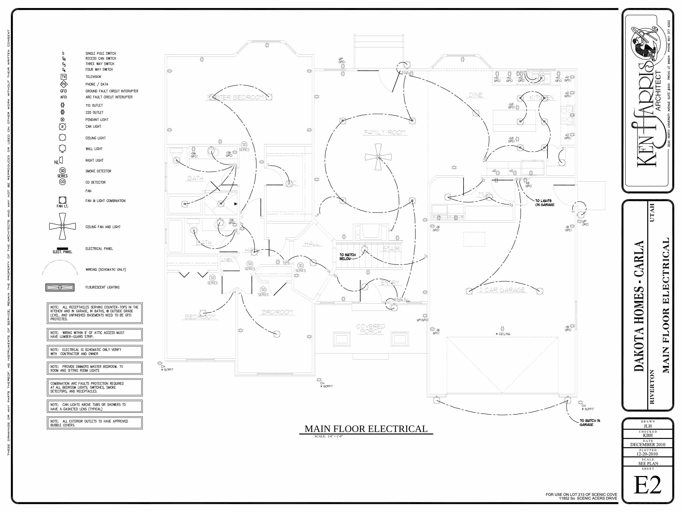
SCALE: 1/4" = 1'-0" MAIN FLOOR ELECTRICAL