q921 de1 lec 5 v1
TRANSCRIPT
Drilling Engineering 1 Course (1st Ed.)
1. Hoisting System:A. The Block & Tackle
a. Hook Power
B. Load Applied to the Derrick
2. Drilling Fluid Circulation SystemA. Mud Pumps
1. Drilling Fluid Circulation SystemA. Mud Pumps (Duplex PDP & Triplex PDP)
B. Solids Control Equipmenta. Mud Cleaners
C. Treatment and Mixing Equipment

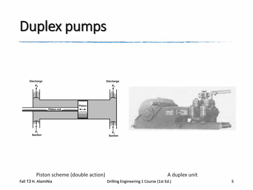
Duplex pumps
Piston scheme (double action) A duplex unitFall 13 H. AlamiNia Drilling Engineering 1 Course (1st Ed.) 5
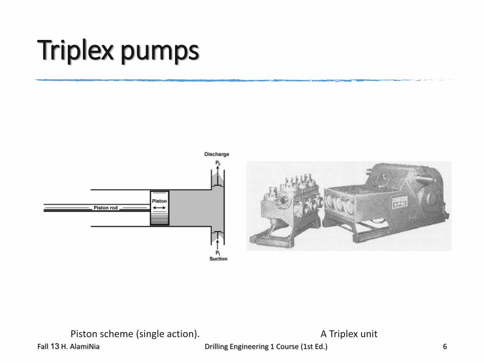
Triplex pumps
Piston scheme (single action). A Triplex unitFall 13 H. AlamiNia Drilling Engineering 1 Course (1st Ed.) 6

the pump factor
The duplex mud pump consists of two double–action cylinders. This means that drilling mud is pumped
with the forward and backward movement of the barrel.
For a duplex pump (2 double–action cylinders) the pump factor is given by:
The triplex mud pump consists of three single–action cylinders. This means that drilling mud is pumped only in the
forward movement of the barrel.
For a triplex pump the pump factor is:
Fall 13 H. AlamiNia Drilling Engineering 1 Course (1st Ed.) 7
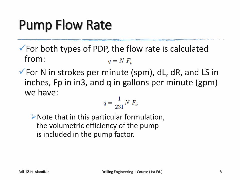
Pump Flow Rate
For both types of PDP, the flow rate is calculated from:
For N in strokes per minute (spm), dL, dR, and LS in inches, Fp in in3, and q in gallons per minute (gpm) we have:
Note that in this particular formulation, the volumetric efficiency of the pump is included in the pump factor.
Fall 13 H. AlamiNia Drilling Engineering 1 Course (1st Ed.) 8
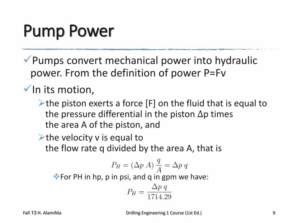
Pump Power
Pumps convert mechanical power into hydraulic power. From the definition of power P=Fv
In its motion, the piston exerts a force [F] on the fluid that is equal to
the pressure differential in the piston Δp times the area A of the piston, and
the velocity v is equal to the flow rate q divided by the area A, that is
For PH in hp, p in psi, and q in gpm we have:
Fall 13 H. AlamiNia Drilling Engineering 1 Course (1st Ed.) 9
pump factor & hydraulic power
Compute the pump factor in gallons per stroke and in barrels per stroke for a triplex pump having 5.5 in liners and
16 in stroke length,
with a volumetric efficiency of 90%.
At N = 76spm, the pressure differential between the input and the output of the pump is 2400 psi. Calculate
the hydraulic power transferred to the fluid, and
the required mechanical power of the pump if Em is 78%.
Fall 13 H. AlamiNia Drilling Engineering 1 Course (1st Ed.) 10
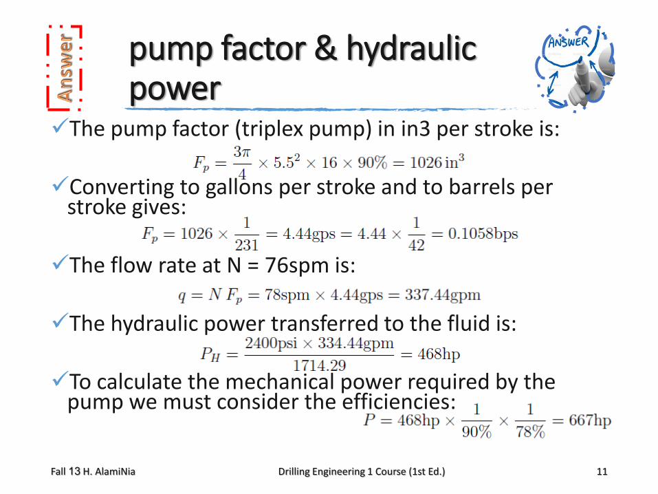
pump factor & hydraulic power
The pump factor (triplex pump) in in3 per stroke is:
Converting to gallons per stroke and to barrels per stroke gives:
The flow rate at N = 76spm is:
The hydraulic power transferred to the fluid is:
To calculate the mechanical power required by the pump we must consider the efficiencies:
Fall 13 H. AlamiNia Drilling Engineering 1 Course (1st Ed.) 11
Surge Dampeners
Due to the reciprocating action of the PDPs, the output flow rate of the pump presents a “pulsation” (caused by the changing speed of the pistons as they move along the liners). This pulsation is detrimental
to the surface and downhole equipment (particularly with MWD pulse telemetry system).
To decrease the pulsation, surge dampeners are used at the output of each pump.
Fall 13 H. AlamiNia Drilling Engineering 1 Course (1st Ed.) 12
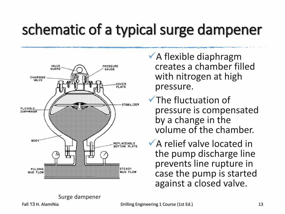
schematic of a typical surge dampener
A flexible diaphragm creates a chamber filled with nitrogen at high pressure.
The fluctuation of pressure is compensated by a change in the volume of the chamber.
A relief valve located in the pump discharge line prevents line rupture in case the pump is started against a closed valve.
Surge dampenerFall 13 H. AlamiNia Drilling Engineering 1 Course (1st Ed.) 13
solids control equipment
The purpose of the solids control equipment is to reduce to a minimum the amount of inert solids and gases in the drilling fluid.
They are:Shale shakers,
Degassers,
Desanders (hydrocyclones),
Desilters (hydrocyclones),
Centrifuges,
Mud cleaners.
Fall 13 H. AlamiNia Drilling Engineering 1 Course (1st Ed.) 15
inactive solids effects
Fine particles of inactive solids are continuously added to the fluid during drilling. These solids increase the density of the fluid and
also the friction pressure drop, but
do not contribute to the carrying capacity of the fluid.
The amount of inert solids must be kept as low as possible.
Fall 13 H. AlamiNia Drilling Engineering 1 Course (1st Ed.) 16
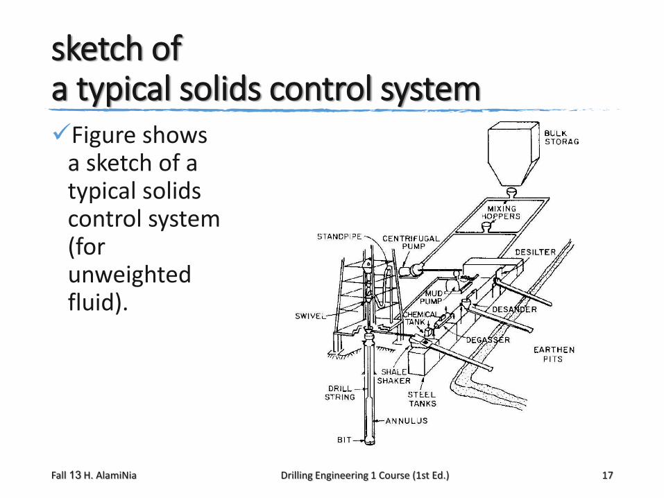
sketch of a typical solids control systemFigure shows
a sketch of a typical solids control system (for unweighted fluid).
Fall 13 H. AlamiNia Drilling Engineering 1 Course (1st Ed.) 17

shale shaker mechanism
The shale shaker removes the coarse solids (cuttings) generated during drilling.
It is located at the end of the flow line.
It constitutes of one or more vibrating screens in the range of 10 to 150 mesh over which the mud passes before it is fed to the mud pits.
Shale shaker configurationsFall 13 H. AlamiNia Drilling Engineering 1 Course (1st Ed.) 18
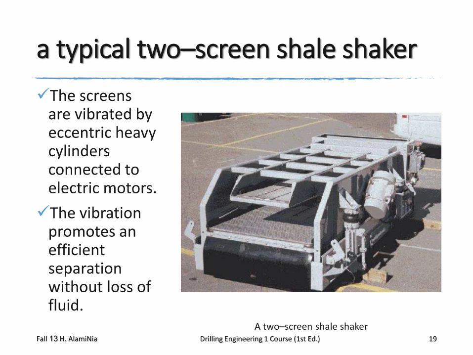
a typical two–screen shale shaker
The screens are vibrated by eccentric heavy cylinders connected to electric motors.
The vibration promotes an efficient separation without loss of fluid.
A two–screen shale shakerFall 13 H. AlamiNia Drilling Engineering 1 Course (1st Ed.) 19

Degassers
Gases that might enter the fluid must also be removed. Even when the fluid is overbalanced,
the gas contained in the rock cut by the bit will enter the fluid and must be removed.
The degasser removes gas from the gas cut fluid by creating a vacuum in a vacuum chamber. The fluid flows down an inclined flat surface
as a thin layer. The vacuum enlarges and coalesce the bubbles. Degassed fluid is draw from chamber
by a fluid jet located at the discharge line.
Fall 13 H. AlamiNia Drilling Engineering 1 Course (1st Ed.) 20
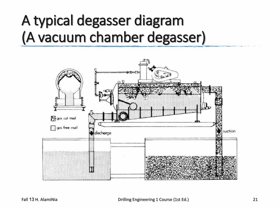
A typical degasser diagram(A vacuum chamber degasser)
Fall 13 H. AlamiNia Drilling Engineering 1 Course (1st Ed.) 21
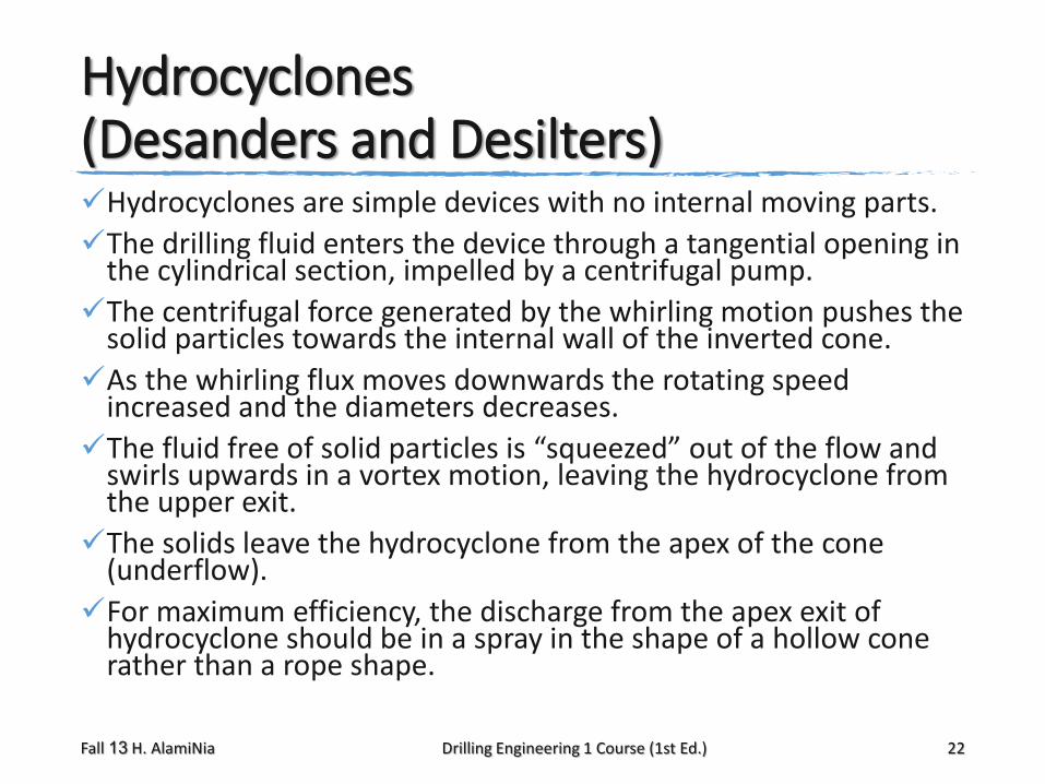
Hydrocyclones (Desanders and Desilters)Hydrocyclones are simple devices with no internal moving parts.
The drilling fluid enters the device through a tangential opening in the cylindrical section, impelled by a centrifugal pump.
The centrifugal force generated by the whirling motion pushes the solid particles towards the internal wall of the inverted cone.
As the whirling flux moves downwards the rotating speed increased and the diameters decreases.
The fluid free of solid particles is “squeezed” out of the flow and swirls upwards in a vortex motion, leaving the hydrocyclone from the upper exit.
The solids leave the hydrocyclone from the apex of the cone (underflow).
For maximum efficiency, the discharge from the apex exit of hydrocyclone should be in a spray in the shape of a hollow cone rather than a rope shape.
Fall 13 H. AlamiNia Drilling Engineering 1 Course (1st Ed.) 22
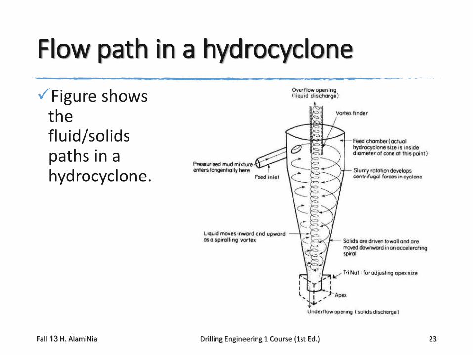
Flow path in a hydrocyclone
Figure shows the fluid/solids paths in a hydrocyclone.
Fall 13 H. AlamiNia Drilling Engineering 1 Course (1st Ed.) 23
Hydrocyclone classifications
Hydrocyclones are classified according to the size of the particles removed as desanders (cut point in the 40–45μm size range) or desilters (cut point in the 10–20μm size range).
At the cut point of a hydrocyclone 50% of the particles of that size is discarded.
The desander is a set of two or three 8in or 10in hydrocyclones, and are
positioned after the shale shaker and the degasser (if used).
The desilter is a set of eight to twelve 4in or 5in hydrocyclones. It removes particles that can not be removed by the desander.
Fall 13 H. AlamiNia Drilling Engineering 1 Course (1st Ed.) 24
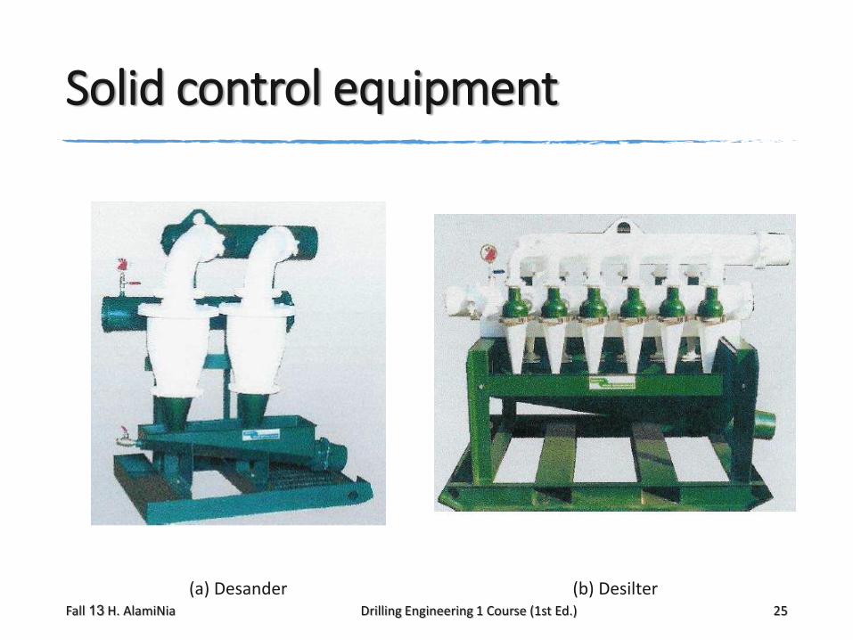
Solid control equipment
(a) Desander (b) DesilterFall 13 H. AlamiNia Drilling Engineering 1 Course (1st Ed.) 25
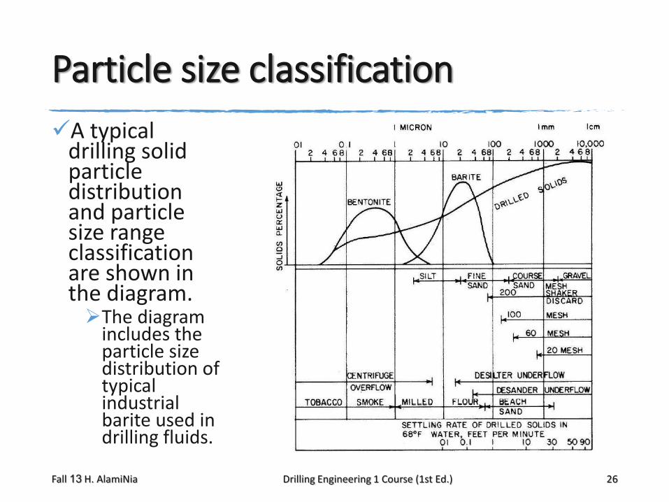
Particle size classification
A typical drilling solid particle distribution and particle size range classification are shown in the diagram.The diagram
includes the particle size distribution of typical industrial barite used in drilling fluids.
Fall 13 H. AlamiNia Drilling Engineering 1 Course (1st Ed.) 26
Centrifuges
The centrifuge is a solids control equipment which separates particles even smaller, which can not be removed by the hydrocyclones.
It consists of a rotating cone–shape drum, with a screw conveyor. Drilling fluid is fed through the hollow conveyor. The drum rotates at a high speed and creates a centrifugal
force that causes the heavier solids to decant. The screw rotates in the same direction of the drum but at a
slight slower speed, pushing the solids toward the discharge line.
The colloidal suspension exits the drum through the overflow ports.
Fall 13 H. AlamiNia Drilling Engineering 1 Course (1st Ed.) 27
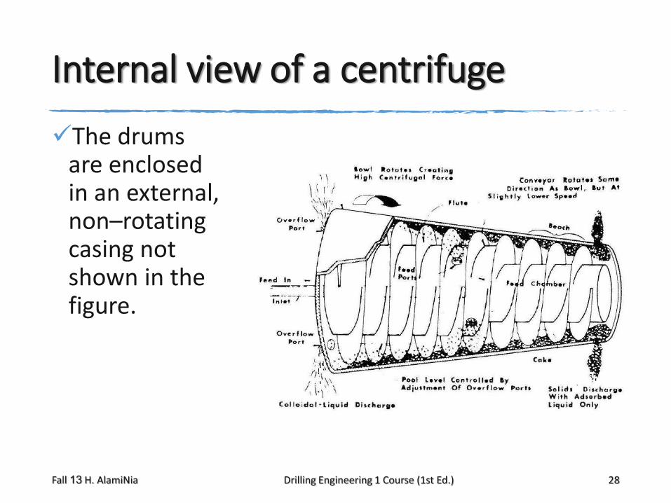
Internal view of a centrifuge
The drums are enclosed in an external, non–rotating casing not shown in the figure.
Fall 13 H. AlamiNia Drilling Engineering 1 Course (1st Ed.) 28

mud cleaner
Inert solids in weighted fluid (drilling fluid with weight material like barite, iron oxide, etc) can not be treated with hydrocyclones alone because the particle sizes of the weighting material are
within the operational range of desanders and desilters.
Weighting material are relatively expensive additives, which must be saved.
A mud cleaner is a desilter unit in which the underflow is further processed by a fine vibrating screen, mounted directly under the cones.
Fall 13 H. AlamiNia Drilling Engineering 1 Course (1st Ed.) 31
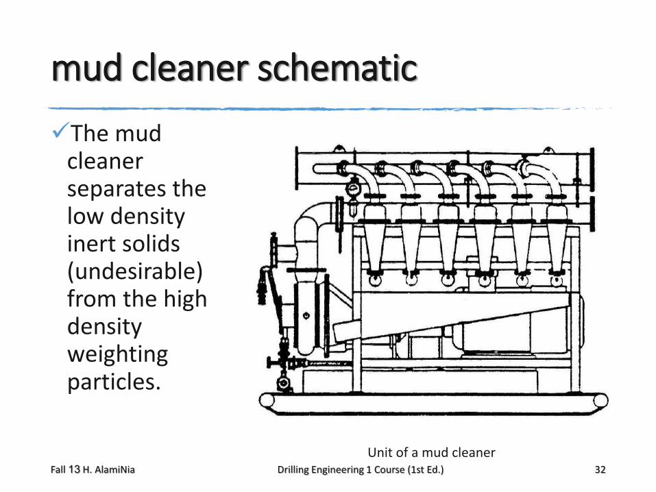
mud cleaner schematic
The mud cleaner separates the low density inert solids (undesirable) from the high density weighting particles.
Unit of a mud cleanerFall 13 H. AlamiNia Drilling Engineering 1 Course (1st Ed.) 32
Hydrocyclones
Hydrocyclones discriminate light particles from heavy particles. Bentonite are lighter than formation solids
because they are of colloidal size (although of the same density).
Barite particles are smaller than formation solids because they are denser.
The desilter removes the barite and
the formation solids particles in the underflow, leaving only a clean mud
with bentonite particles in a colloidal suspension in the overflow.
Fall 13 H. AlamiNia Drilling Engineering 1 Course (1st Ed.) 33
Hydrocyclones (Cont.)
The thick slurry in the underflow goes to the fine screen,
which separate the large (low density) particles (formation solids) from the small (high density) barite particles, thus conserving weighting agent and the liquid phase but at the same time returning many fine solids to the active system.
The thick barite rich slurry is treated with dilution and mixed with the clean mud (colloidal bentonite).
The resulting mud is treated to the right density and viscosity and re–circulates in the hole.
Fall 13 H. AlamiNia Drilling Engineering 1 Course (1st Ed.) 34
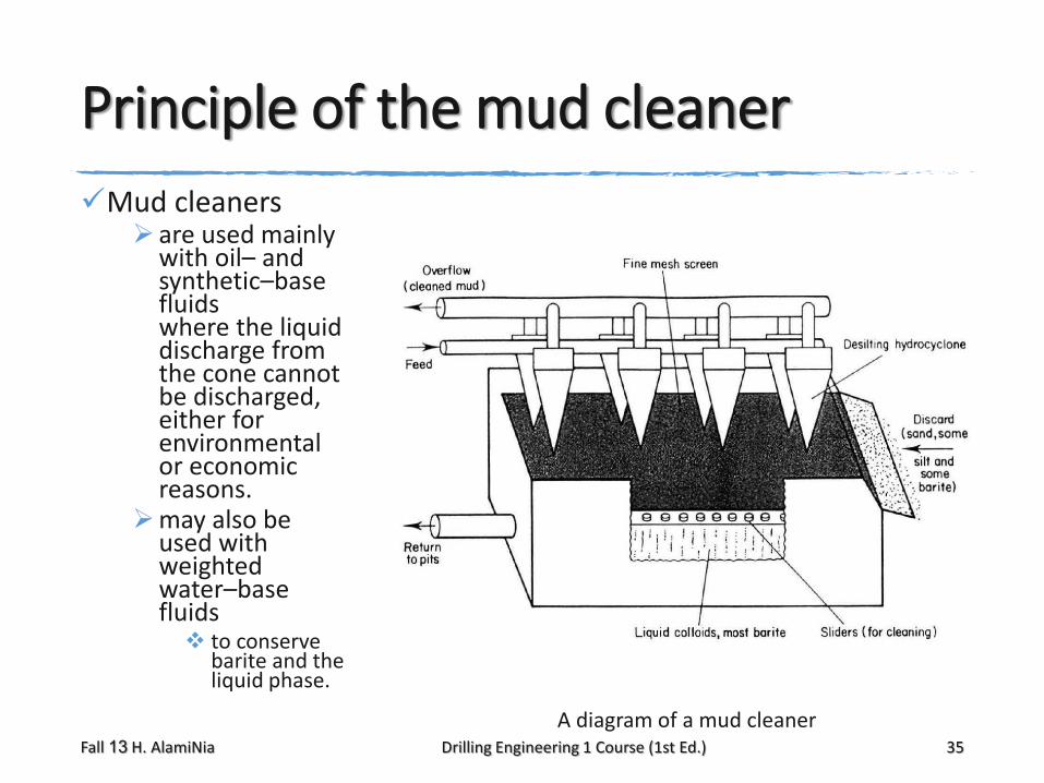
Principle of the mud cleaner
Mud cleaners are used mainly
with oil– and synthetic–base fluids where the liquid discharge from the cone cannot be discharged, either for environmental or economic reasons.
may also be used with weighted water–base fluids to conserve
barite and the liquid phase.
A diagram of a mud cleanerFall 13 H. AlamiNia Drilling Engineering 1 Course (1st Ed.) 35

Drilling fluid components
Drilling fluid is usually a suspension of clay (sodium bentonite) in water.
Higher density fluids can be obtained by adding finely granulated (fine sand to silt size)
barite (BaSO4).
Various chemicals or additives are also used in different situations.
The drilling fluid continuous phase is usually water (freshwater or brine) called water–base fluids.
When the continuous phase is oil (emulsion of water in oil) it is called oil–base fluid.
Fall 13 H. AlamiNia Drilling Engineering 1 Course (1st Ed.) 37
Mixing Equipment
Water base fluids are normally made at the rig site
(oil base mud and synthetic fluids are normally manufactured in a drilling fluid plant).
Special treatment and mixing equipment exists for this purpose.
Tank agitators, mud guns, mixing hoppers, and other equipment are used for these purposes.
Fall 13 H. AlamiNia Drilling Engineering 1 Course (1st Ed.) 38
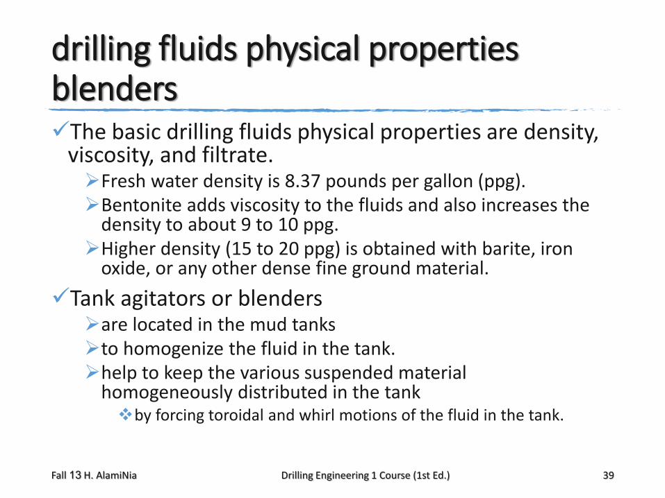
drilling fluids physical propertiesblendersThe basic drilling fluids physical properties are density,
viscosity, and filtrate. Fresh water density is 8.37 pounds per gallon (ppg). Bentonite adds viscosity to the fluids and also increases the
density to about 9 to 10 ppg. Higher density (15 to 20 ppg) is obtained with barite, iron
oxide, or any other dense fine ground material.
Tank agitators or blenders are located in the mud tanks to homogenize the fluid in the tank. help to keep the various suspended material
homogeneously distributed in the tank by forcing toroidal and whirl motions of the fluid in the tank.
Fall 13 H. AlamiNia Drilling Engineering 1 Course (1st Ed.) 39
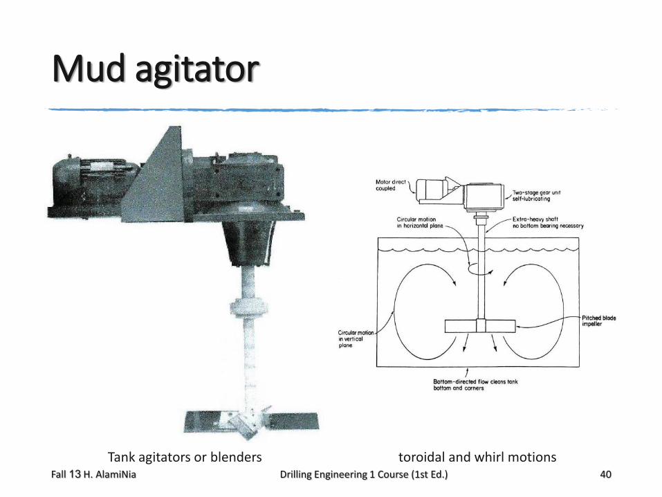
Mud agitator
Tank agitators or blenders toroidal and whirl motionsFall 13 H. AlamiNia Drilling Engineering 1 Course (1st Ed.) 40
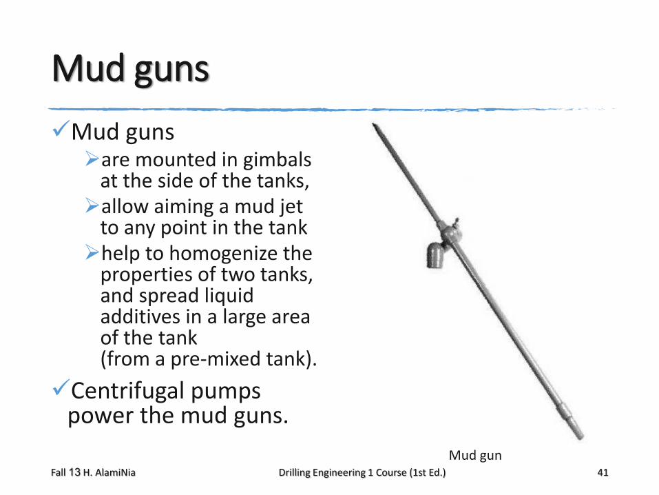
Mud guns
Mud guns are mounted in gimbals
at the side of the tanks, allow aiming a mud jet
to any point in the tankhelp to homogenize the
properties of two tanks, and spread liquid additives in a large area of the tank (from a pre-mixed tank).
Centrifugal pumps power the mud guns.
Mud gunFall 13 H. AlamiNia Drilling Engineering 1 Course (1st Ed.) 41
mixing hopper
The mixing hopper allows adding powder substances and
additives in the mud system.
The hopper is connected to a Venturi pipe. Mud is circulated by centrifugal pumps and
passes in the Venturi at high speed, sucking the substance into the system.
Fall 13 H. AlamiNia Drilling Engineering 1 Course (1st Ed.) 42
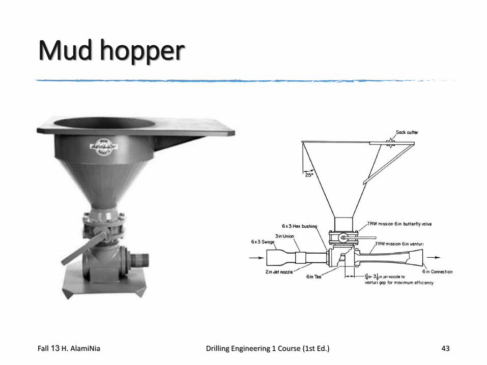
Mud hopper
Fall 13 H. AlamiNia Drilling Engineering 1 Course (1st Ed.) 43
1. Jorge H.B. Sampaio Jr. “Drilling Engineering Fundamentals.” Master of Petroleum Engineering. Curtin University of Technology, 2007. Chapter 2