q,. ~ . ,.. nbsir 76- · experiment was conducted where a pentaprism was tilted through a 9'...
TRANSCRIPT

NBSIR 76-993
The Calibration of a Pentaprism
~ ( . .
Charles P. ReeveRalph C. Veale
Institute for Basic StandardsNational Bureau of StandardsWashington, D. C. 20234
January 1976
Final
".,.1 0' .,. o
. ~
it"'1 ~~(r 0 ~ III
..
1!J
"!:'" .
;J",
!. .. '- .
!'t'
q,. ... ~ ...~ . ,..
"At'AU of
, i
, ~
U. S. DEPARTMENT OF COMMERCE
NATIONAL BUREAU OF STANDARDS

NBS1R 76-993
THE CALIBRATION OF A PENTA PRISM
Charles P. ReeveRalph C. Veale
Institute for Basic StandardsNational Bureau of StandardsWashington, D. C. 20234
January 1976
Final
S. DEPARTMENT OF COMMERCE. Rogers C. B. Morton, SecretaryJames A. Baker. III. UndfH' Sec,etaIVDr. Betsy Ancker-Johnson. Assistant SecretaIV fOf Science IItId Technology
NATIONAL BUREAU OF STANDARDS. Emest Ambler. Acting Di,ecto,

CONTENTS
In t roduc t ion
---------------------------------------------
Description and Uses -------------------------------------
Geomet r ical Models ---------------------------------------
Angular Errors between Faces - Transmitted Beam ----
Angular Errors between Faces - Reflected Beams -----
Errors in Vertical Alignment with Incident Beam ----
Maximum Deviation of Incident Beam from Normal -----
Method of Calibration ------------------------------------
Setup Procedures -----------------------------------
Measurement of Parameters --------------------------
1. Deflection Angle of Transmitted Beam -------2. Angle between Reflec ted Beams --------------3. Indices of Refraction ----------------------4. Interior Angles ----------------------------
Effects when Indices of Refraction Change ----------------
Examp Ie
---- -- ------------ -------- -- ----------------------
oncl us i on
---- ---------------------- ---------------- ----
Tables 1 and 2 -----------------------------------------------
Tables 3 and 4 -----------------------------------------------
Re f e renc e s
--------------------------------------- ------------
Page

THE CALIBRATION OF A PENTAPRISM
Charles P. Reeve and Ralph C. Veale
Introduction
The Dimensional Technology Section is currently responsible forthe calibration of pentaprisms at the National Bureau of Standards.This responsibility requires that we be familiar with
a good method of calibrating pentaprisms
their common uses
effects errors their internal geometry, and
effects errors their alignment with beam light.Information which we have been able to obtain on the above subjects iscurrently quite scattered throughout different sources and needs to beunified. Additionally, through investigation carried out at the Bureau,we have learned some important facts relative to the functioning of apentaprism that we have been unable to find documented anywhere else.Therefore, the purpose of this paper is to collect from these sourcesall the facts about pentaprisms which we believe are relevant to theircalibration and usage. These facts are discussed individually in thefollowing sections where material is liberally incorporated from thereferences.
Although some of the mathematics may appear awesome, the resultsare fairly simple. The method of calibration is also simple and thedata reduction can easily be done by hand with the aid of a small ca1-cu1a tor "
Description and Uses
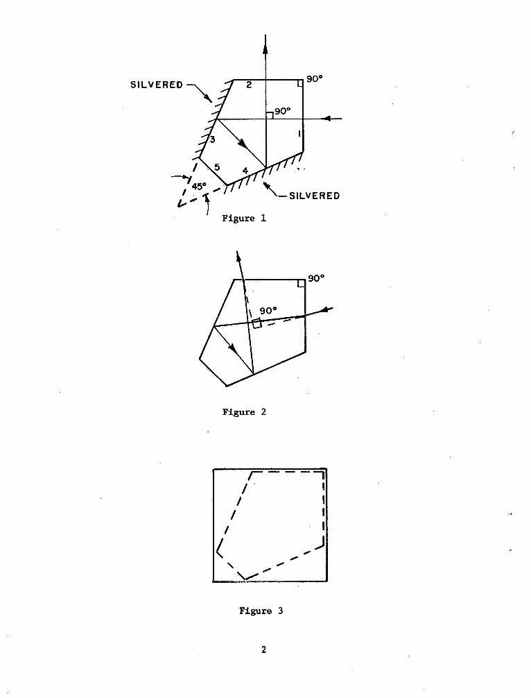
The word pentaprism is a commonly used contraction of "pentagonalprism" which, as its name indicates, is a five-sided prism (fig. 1).It is one of a class of objects known as "constant deviation prismswhose purpose is to bend a beam of light exactly 900 regardless of the
900
45O
L-" 1 Figure 1
Figure 2
- -
-'1
..........
Figure 3

angle of incidence of the light. Each of the five faces is perpendicu-lar to both the base and the top. Faces 1 and 2 serve as entry andexit planes for a beam of light, and the angle between them is nominally900 Faces 3 and 4 are silvered and serve as reflectors, and the anglebetween them is nominally 450 Face 5 serves no purpose other thantruncating the unusable portion of the wedge between faces 3 and 4.
The function of the pentaprism is governed by the law of reflectionwhich states that if an incident beam o~ light is reflected off twoplanes, then the reflected beam is bent by an angle which is equal totwice the supplement of the acute angle between the reflectors. Thusin a pentaprism the beam deviation is 2 (180 - 45) 0 = 2700 It caneasily be shown that if the incident beam is not normal to the facewhich it enters, it will be refracted on entry and exit but throughthe same angle so that the effects cancel each other (fig. 2). course this assumes that the entry and exit faces are exactly 900apart. The case where that is not true is covered in the next section.
Sometimes a pentaprism is mounted in a square metal housing withground locating faces and is called an optical square (fig. 3), refer-ring to its functional use. The faces of the pentaprism are usuallymounted not quite parallel to the corresponding faces of the mount toavoid ghost reflections directly off the prism face when the mount isaligned to the line of sight. This is especially important if theoptical square is being used with an autoco11imator because the ghostimage could interfere with the returning beam.
A pentaprism (optical square) is useful in many types of opticalmeasurements where the line of sight or a beam of light must be turnedat a right angle. For example, it may be used with an autoco11imatorto check the parallelism of internal surfaces, perpendicularity of atranslational movement, or relative squareness of two or more machinesurfaces. These and other eJtamples are given in Farago Ii) * andHume (2, 3).
Geometrical Models
In the past it was usually assumed that if a pentaprismwas ob-served to bend a beam of light within a few seconds .of a right anglethen the 450 and 900 angles must also be within a few seconds of nominal.This has been found to be an erroneous assumption. A recent samplingof five pentaprisms indicated that the 900 angle is likely to deviateseveral minutes from nominal. In view of this it is mandatory to ex-amine the effects of such deviations. This is accomplished in the nexttwo sections. Also considered will be two characteristics of a "per-*Numbers in brackets indicate references listed at the end of this paper.
900 + a
900
900
+ '"
900
Figure 4

fect" pentaprism: the effects of tilting it in a vertical plane andits usable angular range of incident light.
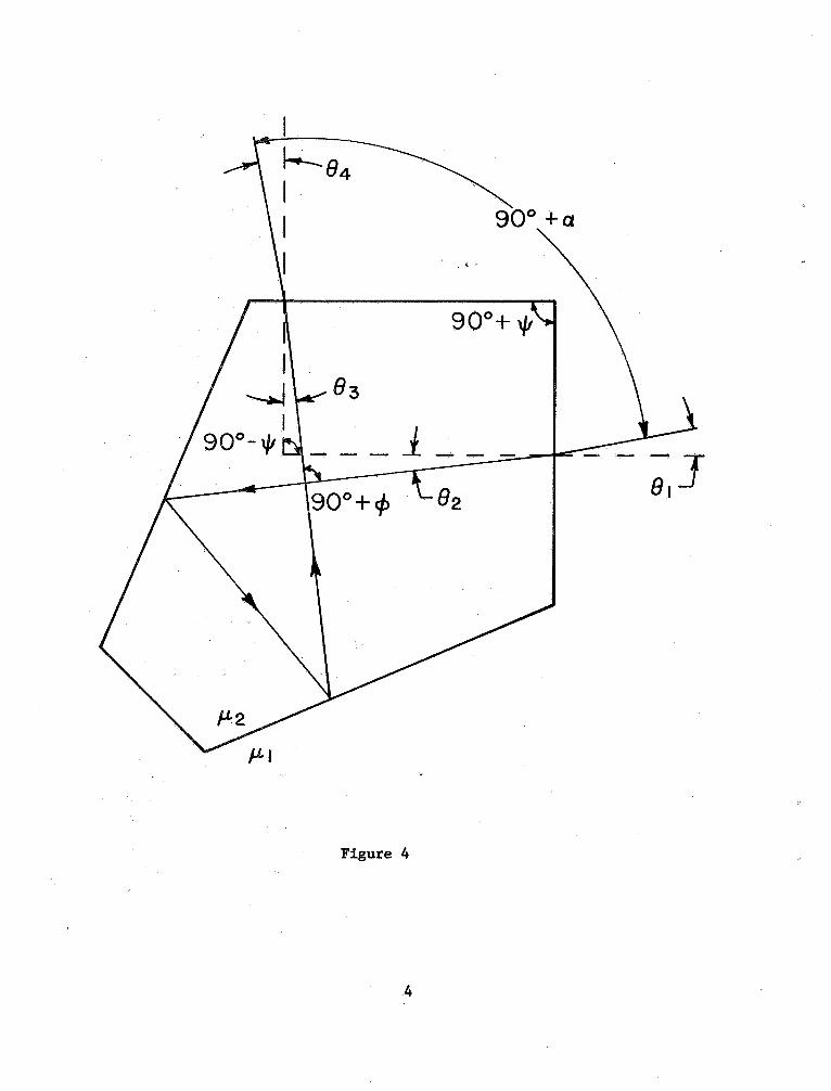
Angular Errors between Fac~s - Transmitted Beam
Assume here that the 900 angle between the faces is in error by asmall amount ~ and that the internal bending of the beam is in error by
a small amount ~ due to an error of t in the 450 wedge angle. The path
of a transmitted beam in a horizontal p:ba:ne is shown in figure 4. Letthe observed bending angle of the beam outside the pentaprism be given by900 + a. It is then essential to know a as a function of ~, ~, 8
1' ~and ~
2 where 8 1 is the deviation of the incident beam from normal
, ~
is the index of Fefraction of the medium (usually air), and ~2 is the
index of refraction of the pentaprism. Assume all angles in figure 4are positive as shown. Then 900 - ~ + 8
3 - 82 = 900 + ~, or
~ + ~ = 8 - 8 (3-
and 900 - ~ + 84 - 81 = 900 + a, or
a+~= (3-
The refraction law gives
l sin 81 = ~2 sin 82' and
(3-3)1 sin 84 = JJ2 sin 8
Writing these equations in the form
a =4 - 81 - ~,
4 = Sin -l(:isin 8
(3-
3 = ~ + ~ + 8
. -12 = 1n nn l

and substituting from bottom to top gives the expression
. =
5111 -i 01nt- + '" + S1n -
(~~
01n ~
m - ~i c
",.
(3-
Using the power series expansions for sine and arcsine functions andignoring all powers of 8
1 greater than two and powers of ~ + $ greaterthan one, equation (3-5) reduces to the approximation equation
. .
a ~
~ +
- 1) $ + ) (~ + $) 8i. (3-
Let a (~, $, 81' ll l' ll ) be the representation of a func tion of the
five variables in the system, and note that
a(O, 0, 81' 111' ll ) = a (3-7)
in both the true (3-5) and approximate (3-6) expressions for a. Thisindicates that a well-made pentaprism is a true square for all normaland off-normal beams.
Let Aa be defined by
Aa = a(~, $, 81' ll l' ll ) - a(~, $, 0, lll' 11
(3-
Then Aa is the fluctuation of a as 81 varies from zero to some maximum
value. In equation (3-5) this fluctuation is a maximum when ~, $, and
1 all have the same algebraic sign. In table 1 Aa is evaluated using
equations (3-5) and (3-6) for specific values of ~, $, 81' )11' and 11
The values from the approximate expression (3-6~ are in parentheses.It is obvious that the approximate expression is very good over thisrange of values for the arguments. The effectiveness .of the pentaprism,in terms of the small magnitude of Aa caused by manufac turing angleerrors ~. and $ and alignment angle. error 8
1' is impressive.
Angular Errors between Faces ~ Reflected Beams
Figure 5 illustrates the paths of the two most intense reflectedghost" beams for the pentaprism. The angle between these beams,
Z~ = 87 - 88' is a function of
~, $, 81' lll' and 112' Later it will*When evaluating this expression angles must be expressed in radians.

~ 900
'" p..
FigureS
t--

be shown how the measurement of 2~ in conjunction with the measure-ment of a can be used to calibrate the interior angles of the penta-prism.
Assume that all angles in figure 5 are positive as shown,' Then
900 - ~ + 83 - 82 = 900 + ~, or
~ + ~ = 83 - 8 (3-9)
and 900 - ~ - 85 + 86 = 900 + ~, or
~ + ~ = .
6 - 8(3-10)
The refraction law gives
1 sin 8 1 = 112 sin 82 and
1 sin 8 7 = 112 sin 8(3-11)
and the reflection law gives
e = and
8 = 8 (3-12)
Writing these equations in the form
. 2~ = 87 - 8
8 = 8
7 = Sin sin 86 '
6 = ~ + ~ + 8 (3-13)
5 = 8
3 = ~ + ~ + 8
2 = Sinsin 81 '
and substituting from bottom to top gives the expression
2~ ;:: Sin - sin (2 (~ + 1/1) + Sin - sin e
)1! -: e (3-14)
When 2~ is measured with an autoco11imator the pentaprism is of neces-sity adjusted so that e
l is small (usually less than 51
).
Thereforeequation (3-14) can be reduced using the first order approximations tothe .sine and arcsine functions to give the approximation equation
2~ = ...l.(~ 1/1). (3-15)
Errors in Vertical Alignment with Incident Beam
Now consider the c.ase of a perfect pentaprism where the incidentbeam is not perpendicular to the pentaprism face in a vertical plane.Assume that the incident beam is horizontal but the pentaprism is tiltedtoward the beam by an angle T as shown in figures 6 and 8~ It is natu-ral to assume that the transmitted beam would show both a vertical andhorizontal component of change from the T = a position (fig. 7). experiment was conducted where a pentaprism was tilted through a 9' arcwith a sine bar and the vertical and horizontal changes in angle wereread by an autocol1imator. The observed .data are given in table 2..There is apparently a one-to-one correspondence between the tilt angleand the vertical deflection of the beam, but no correspondence betweenthe tilt angle and the horizontal deflection of the beam. The verticaldeflection may be of interest in certain situations, but not in thecalibration process since theautocollimators are set to read horizontalangle only. Therefore consideration will be given only to deflection inthe horizontal plane.
It is interesting to verify geometrically that the tilt angle doesnot significantly affect the angle of deflection horizontally. When thepentaprism is ina horizontal position with T=O as shown in figure 7,consider the points a, b, and c which lie at the intersection of theplane z=h and the thre.e vertical edges which form the 450 wedge angle.(Note that the point c 1ies on the truncated edge ~ Let the pentaprismbe tilted by rotating it about the x axis through an angle T, and con-sider the new points a , b' , and c ' which lie , at the intersection ofthe plane z=h and the same three vertical edges respectively as shownin figures 6 and 8. By calculating the (x:, y) coordinates of the sixpoints the apparent change in the horizontal wedge angle y can becomputed. The coordinates are as follows:

r...
....... ~... -+-
I a Y - -
-- - \- - - - - - - -
Figure 6
Y! r:,
.......
b I
. ' ,.
1-
- ~- - - - - -
1. r"O
~~
--1Figure 7
. "
d I -r --L
--+- j/;j
aI
. -
+(1 9O
T ~O
Figure 8

oint
, y
oint
(d, 0)
(x,y)
(d e sin '
COS "
(O,
(e,
(0,
~ .
sincos .
(e, e cos .).
If the origin is shifted to point c ' then the coordinates of a ' and b'become - sfu~ (d-e, - e cos .) = (d-e, ) andcos . cos .
(-e, cos .e sin. d-ecos. - e cos .) = (-e,
cos T
respectively- Consider these two points to be vectors A = (aI' a
) and
B = (bl' b
) in the (x,y) plane and recall that the expression for their
dot product can be writtenA-B
COS Y
' =
TATfBT(3-16)
where A-B = a1 + a 2' IAI=
ai + a;, IBI"'; bi + b;, and y ' is the
angle between the vectors. Then
cos y
' =
e (e-d) + e (e-
cos .(3-17)
~4,",,)Z + 'z 1 r.
z + (4-
;)
coa . J L cos .
Substituting d = eel - tan 22 1/20 ) = e(2 -
~)
into eq. (3-17) gives
cos y
' -
cos
. +
6cos . +l(3-18)
Let y ' = y + ~y = 450 + ~y. Then

A - cos T + 1oy - os
- "
cos T + 6 cos T + 1(3-19)
Now consider the effect of l::.y on the deviation a ' of the reflectedbeam from a right angle inside the prism (fig. 8). The reflection lawgives 2700 + a ' = 2(1800 - y ) = 2(1800 - 450 - Ay) = 2700 - 2l::.y, h~nce
' = -
2Ay., (3-20)
Since the exiting beam is not perpendicular to the prism face it isrefracted. The resulting deviation a of the reflected beam from a rightangle outside the prism is related to a '
a = S1n S1n a (3-21)
hence
a = Sin Sin(-2l::.Y). II (3-22)
Substituting eq. (3-19) into eq. (3-22) gives
a = Sin
t::::4: ::
cos OU)
cos T +1)(3-23)
If T is small then eq. (3-23) can be approximated by
:::::
(3-24 )
Values of a are computed for selected values of T in table 3 using,the exact equation (3-23) and the approximate equation (3-24). It isvery clear from table 3 that any tilt angle less than 30 has no measur-able effect on the reflected beam in the horizontal plane. Since thetilt dur~ng calibration is never more than a few minutes, the tilt anglecan be dismissed as a cause for concern.
It should be noted that a tilt along the 'base of the face which isperpendicular to the one just considered gives the same effect since thepentaprism functions in a symmetric manner.

Maximum Deviation of Incident Beam from Normal
Occasionally it may be of interest to know the range of incidentbeam angles for which there is transmission through the pentaprism.The two extreme Cases (for a perfect pentaprism) are shown in figure 9where e
i is the deviation of the incident beam from normal and er is thedeviation of the refracted beam from normal. Some mathematical manipu-lation gives the result
r = Tan 2 ;
);=.
160 19' 29.. (3-25)
henceJ.l J.l
e i = Sin sin e == SinJ.l r J.l 7 +
(3-26)
If J.l1 = 1.0 and J.l2 = 1.5, then ei = 240 56' 14.
For incident beams entering at the center of the face (fig. lO),the maximum deviation is
r = Tan \12 = 80 19' 53. (3-27)
hence
i = Sin -sin e = Sin -
, J.l
J.l 5 + 16.'2(3-28)
If J.l l = 1.0 and J.l2 = 1.5, then ei = 120 33' 12.
Method of Calibration
Th~ method of caLibrating ex has been in use at the National Bureauof Standards for several years and has similarities to a method describedby Hume (3). The method of calibrating the remaining parameters wasrecently developed at, NBS and has been implemented as part of the cali-bration service.

Figure 9
Figure lO

Setup Procedures
The measurement setup calls for a surface plate, two autocol1i-mators, .and two high quality front surface type mirrors The auto-collimators and mirrors are set on the surface plate as shown in fig. 11.The mirrors should be mounted so they are perpendicular to the surfaceplate. The angles between the axes of the autoco11imators and the per-pendiculars to the mirrors should be clos.e enough to 900 that eitherautocol1imator will read on scale with any of the four possible orien-tations of the pentaprism. This can be accomplished by placing thepentaprism so that it reflects the beam~rom autocol1imator A intomirror 1. Mirror 1 is adjusted until autocollimator A reads on scale,then the pentaprism is rotated 900 so that it reflects the beam fromautoco11imator B into mirror 1. Autoco11imator Bis adjusted so thatit reads on scale, then the pentaprism is rotated another 900 so thatit reflects the beam from autocollimator B into mirror 2. Mirror 2 isadjusted so that autoco11imator B reads On scale. At this point every-thing should be adequately aligned, but as a check the pentaprism shouldbe rotated 900 again to be sure that autoco11imator A and mirror 2 areproperly aligned.
Each autoco11imator should be checked for reading vertical angleby tilting the pentaprism slightly toward it and observing a change inreading. If there is nO change then the autoco11imator is properlyreading horizontal angle only. After all adjustments are completedthere should follow a period of waiting time for temperature stabili-zation.
Measurement of Parameters
In the normal usage of a pentaprism the angle of deflection of thetransmitted beam, a, is considered to be the most important parameter.However , in a high precision calibration of a pentaprism it is necessaryto know the magnitude of othe.r parameters which may affect a in certainsituations. The methods of measuring these parameters are outlined inthe following sec tions .
Deflection Angle of Transmitted Beam
Le~ the angles between the autocol1imator axes and the perpendicu-lars to the mirrors be given by 900 + 8
1' 900 + 82' 900 + 83' and 900 + 8as shown in figure 11. (The autocollimator axis is taken to be the linealong which the collimated light exits. Readings are made with the penta-prism in each of its four positions. Care should be taken that with eachreading the front surface reflection of the pentaprism is outside thefield of view of the autoco11imator. The readings take the form

MIRROR I
AUTOCOLLIMA TOR
90. + IJ.909 -I- 134
'=J900 +
900 + ~ 2
AUTOCOLLIMATOR
Figure II
MIRROR 2
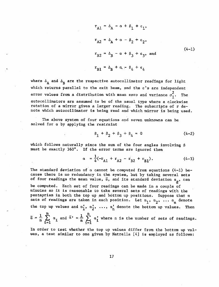
r Al = AA - a + Sl + €
r A2 = AA + a - S2 + €
(4-l)B2 = AB - a + S3 +€3' and
Bl ~ AB + ~ ~ S4 + €
where AA and AB are the respective autocollimator readings for light
which returnS parallel to the exit beam, and the € ' S are independenterror values from a distribution with mean zero and variance l' The
autoco11imators are assumed to be of the usual type where a clockwiserotation of a mirror gives a larger reading. The subscripts of r de-note which autoco11imator is being read and which mirror is being used.
The above system of four equations and seven unknowns can besolved for a by applying the restraint
l + S2 + S3 + S4 = a(4-
which follows naturally since the sum of the four angles involving Smust be exactly 3600 If the error terms are ignored then
(-rAl + rAZ - r~2 + r (4-
The standard deviation of a cannot be computed from equations (4-1) be-cause there is no redundancy in the system, but by taking several setsof .four readings the mean value, iX, and its standard deviation s , can
be computed. Each set of four readings can be made in a couple ofminutes so it is reasonable to take several sets of readings with thepentaprism in both the top up and bottom up positions. Suppose that nsets of readings are taken in each position. Let a
I' a2' ... an denotethe top up values and ai, ai, ..., a~ denote the bottom up values. Then1 n 1 .a = - 2: a
i and ix' =
- 2: aI where n is the 'number of sets of rea,dings.n i=l n i=l
In order to test whether the top up values differ from the bottom up val-ues, a test similar to one given by Natrella (4) is employed as follows:
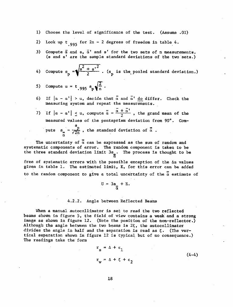
Choose the level of significance of the test. (Assume . 01)
Lookup t . 995 for 2n - 2 degrees of freedom in table 4.
Compute and s, a' and s ' for the two sets of n measurements.(s and s ' are the sample standard deviations of the two sets.
Compute s
",,
2 ; s. (sp is the, pooled standard deviation.
Compute u = t . 995 /"nIf la - a l ~ u, decide that a and a' do differ.measuring system and repeat the measurements..
a + a'If I a - a I I :: u, compute a
==
' the grand mean of the
measured values of the pentaprism deviation from 900 Com-
pute s
= =
' the standard deviation of a
Check the
The uncertainty of a can be expressed as the sum of random andsystematic components of error. The random component is taken to bethe three standard deviation limit 3s The process is thought to be
free of systematic errors with the possible exception of the Aa valuesgiven in table 1. The estimated limit, E, for this error can be added
to the random component to give a total uncertainty of the a estimate of
U = 3s +
Angle between Reflected Beams
When a manual autocollimator is set to read the two reflectedbeams shown in figure 5, the field of view contains a weak and a strongimage as shown in figure 12. (Note the position of the non-reflector.Although the angle between the two beams is 2~, the autocollimatordivides the angle in half and the separation is read as ~. (The ver-tical separation shown in figure 12 is typical but of no consequence.The readings take the form
r s = A + 8(4-
w = A + ~ + 8

WEAKIMAGE
....
NON-REFLECTOR
AUTOCOLLIMATOR
Figure 12
STRONGIMAGE

where the subscript s of r denote which image is being read. The ~are independent error values from a distribution with mean zero and
variance cr2' Ignoring the error terms as in the previous section, then~=r -r (4-5)
~ = -
1n j=l jSeveral pairs of measurements are made and the mean value,
and its standard deviation, s , are computed' where 1n is the
number of .pairs of readings. (Again the sign of ~ is correct if theautoco11imator is of the usual type.
An explanation should be given for the difference in intensityof the two reflected beams. One beam obviously loses some of itsintensity while bouncing around inside the pentaprism. Let
I = intensity of incident oeam from autocollimator,
p =
reflectivity of entrance and exit faces, and
p =
reflectivity of silvered faces.
Then the intensity of the strong reflected beam is
I = P I, (4-
and the intensity of the weak reflected beam is
I = p (l - ~ ) 2 (4-
Their ratio is
~ -
(1
-- p )
p 4
I - (4-
Obviously this ratio may 'vary considerably depending particularly Onthe refl.ectivity of the silvered faces of the given pentaprism. Some-times the images may be so nearly equal in intensity that one cannotbe definitely identified .as the weaker. In that Case some grease Canbe applied to the pentaprism face which is 900 away from the auto-collimator and the weaker image will gradually disappear.

Indices of Refraction
A perfect pentaprism functions independently of its index ofrefraction, but an imperfect pentaprism does no.t. To some degreethe index of refraction must be included in the characterization ofits performance. It is not a practical matter to measure the indexof refraction every time a pentaprism is calibrated, so certain as-sumptions have to be made. The manufacturer s value for the indexof refraction, if available, is taken to be the correct value. Other-wise the value J.l2 = 1. 5 is used. This .cprresponds clQse1y to the
average" value for crown glass. The index of refraction of the airis taken to be J.l1 = 1.
Interior Angles
The mean value a which was computed in section 4. 1. can besubstituted into equation (3-6) t.o give
- J.l J.l
a==-
q,+-
-11/lJ.ll ' J.l
(4-9)
where the 6~ term is dropped since 61 is purposely kept very small.
Similarly the mean value ~ which was computed in section 4. 2. canbe substituted into equation (3-15) to give
~ =
J.l
q, +
J.l
1/1J.ll J.l
(4-10)
From equations (4-9) and (4-10) the estimates q, and 1/1 are computed to be
. = (
- ~ ~ + a
and (4-11)
1/1 = E; - C1.
Let y be the deviation from nominal of the 450 angle of the pentaprism(a slight change in notation from section 3. ). By the reflectionproperties
y = -
(4-12)
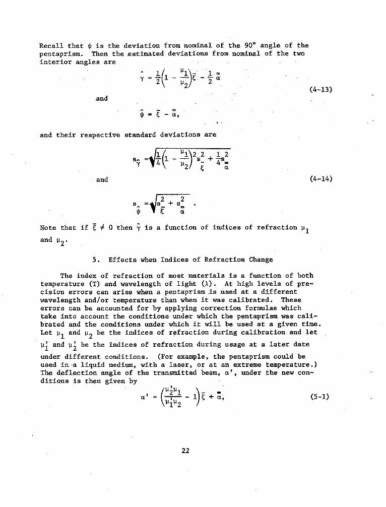
Recall that IjI is the deviation from nominal of the 900 angle of thepentaprism. Then the estimated deviations from nominal of the twointerior angles are
~ =
(1 -
:~)
f -
(4-13)and
1/1 = f; - a,
and their respective standard deviations are
2 2 1 2SA = 1 - -- s
- + ~=
y Pand (4-l4)
+ s
...
IjI f; Note that if f ~ a then y is a function of indices of refraction P
and P
Effects when Indices of Refraction Change
The index of refraction of most materials is a function of bothtemperature (T) and wavelength of light (A). At high levels of pre-cision errors can arise when a pentaprism is used at a differentwavelength and/or temperature th~n when it Was calibrated. Theseerrors can be accounted for by applying correction formulae whichtake into account the conditions under which the pentaprism WaS cali-brated and the conditions under which it will be used at a given time.Let P
I and P2 be the indices of refraction during calibration and let
pi and P2 be the indices of refraction during usage at a later dateunder different conditions. (For example, the pentaprism could beused in.a liquid medium, with a laser, or at an extreme temperature.The deflection angle of the transmitted beam, a , under the new con-ditions is then given by
PiP
= ---,----
If+a, (5-l)

and its standard deviation is given by
s ,Gi~ - 02
.~ + s~ (5-
The upper bound on the error associated with a ' due to a non-zeroincident beam angle is given by
112 111.
t:.aIII 112
~ 8 (5-
where 81 is the largest value of the incident beam
s deviation from
normal.
In order for the user to make these corrections (if he so chooses),
the values T, A, l' 11
~, s ' and s are all given in the Report of
Calibration. The values
.y, ~,
SA, and SA are also given.1jJ
Example
The data sheets for a sample pentaprism calibration are shown infigures 13 and 14. Four sets of measurements of a were made in boththe top up and bottom up positions. The statistical test shows thatthere is no significant difference between the two mean values. Foursets of measurements of ~ were made in the top up position. The indexof refraction values were estimated and the remaining parameters com-puted.
~.~
Suppose that this pentaprism were later used in the followingtwo ways.
Case Pentaprismused with a laser for which the index ofrefraction was 1% higher than during calibration.
Pentaprism used in an underwater test where = 1. 33.
In both cases assume ,that the maximum incident beam deviation fromnormal (8 ) Was 50 , and that II
I ~ 1.0 and = 1.5. Using the methods
of section 5 the following parameters can be computed.
Case II:

top up
bottOQ1 up
top up
bottOQ1 up
top up
bottom up
top up
bottom up
top up
bottom up
top up
bottom up
top up
bottom up
ap up
bottom up
sets (n) -
ken)
925604707355169055977
CALIBRATION OF A PEN'XAPRISM (OPTICAL SQUARE)
Lot jSt3Sex-tal To if- 7 2 ;3.0 ,
sheet 1 of 2
(N es)Observer CP R. ~ I!. c:
Date J.J 2.0 / 75"
Go.
7.
7, ,
"7.
.,a ' . t(- rAl + rA2 - rB2 + rtop up (a) bot tOlD up (a
-,
S:-OO
11. ,
.,.
fl.
2.. .3
If (b) ~ (a) , check 1IIe~8urlng system and repeat measurements.
- i + 4' J A.C If (b) S (a) , compute a - ---r- -
~ ,
and s .. .J!.. 0 z..1
;: v'2n
-I. 4-15"Z. I 2-
2 ,
2.. 2.
- ,. 315'
- " .350
Z. 3
mean (0 .and ; '
) -
std. dev. (. and s '
) -
2 + s ,s . I 4- 2.S
()73'
, () 5"8'+
ken) . 3. 707
u . k(n)*. *- ff. - . /54- (a)p 1n-
I. - ill - (b)
Figure l3
- , .
S'oc;
I. 4- z,S
I. 5'00
I , +So
+,
037~
5/75

CALIBJW:ION PENTAPRISM (OPTICAL SQUARE) sheet
G~~Lot QS4-3 Observer Cp~
...
/I..
Serial 4-72301 Date 2.0 /7SEstimated indices refraction Temperature (T) %.0,
Estimated wavelength
AI"" light
(~)
image reading weak strong
weak .L lff.48. z.. 3C1.
.,
strong
weak Z8.10.ff.Itrong
weak 28.SO.
38.strong
"Weak ....5..- 1ll.
-L.. 4-1. ..1-' to.strong
weak
strong
weak
strong
sets (m) mean (E) 2.. 3'1.
std. dev. (s) 11l.
3tt
. -
l)i ~'- 5+..
'-"(- -
+ Q
,..
-l; 2.7. t(l 1 2 1 2'Y - TiS
Figure 7/75
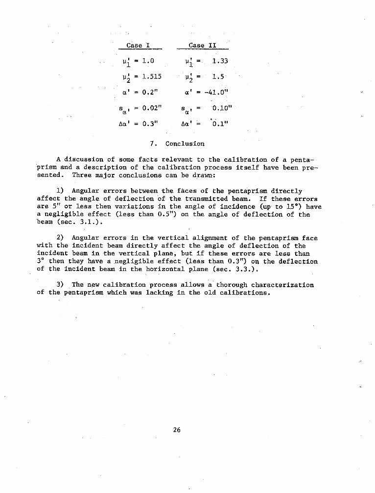
Case I Case II
111 = 1.0
112 = 1.515
' =
1.33
' =
1.5
' = 0.
' = -
41.
' = 0. 02"
' = 0.
' =
10"
' = . .
Conclusion
A discussion of some facts relevant to the calibration of a penta-prism and a description of the calibration process itself have been pre-sented. Three major conclusions can be drawn:
1) Angular errors between the faces .of the pentaprism directlyaffect the angle of deflection of the transmitted beam. If these errorsare 5" or less then variations in the angle of incidence (up to 150) havea negligible effect (less than 0. ) on the angle of deflection of thebeam (sec. 3.1.).
2) Angular errors in the vertical alignment of the pentaprism facewith the incident beam directly affect the angle of deflection .of theincident beam in the vertical plane, but if these errors are less than30 then they have a negligible effect (less than a . ) on the deflectionof the incident beam in the horizontal plane (sec. 3.
3) The new calibration process allows a thorough characterizationof the pentaprism which was lacking in the old calibrations.
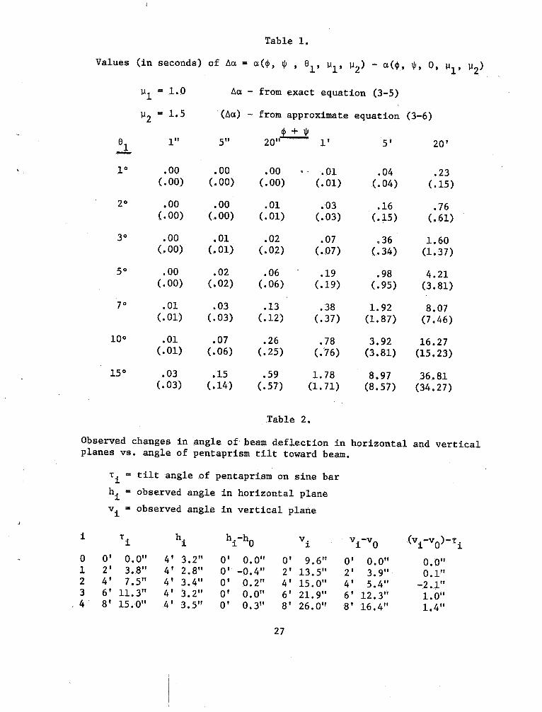
Table 1.
Values (in seconds) of Aa. = a.(cf1, lji , aI' \.11' \.1 a.(cf1 lji, 0, \.I
1.0 Aa. from ~xact equation (3-5)
\.1 1.5 (Aa.) from approximate equation (3-6)
20'20"
1 0 . 00 . 2300) ( . 00) 00) 01) 04) 15)
00) 00) 01) 03) 15) 61)
3(1 1.60( . 00) 01) 02) ( . 34) (1.37)
00) 02) 06) 19) 95) (3. 81)
1.9201) 03) 12) 37) (1. 87) (7. 46)
100 16. 2701) 06) 25) 76) (3. 81) (15. 23)
150 1. 78 36.03)
( .
l4) 57) (1. 71) (8. 57) (34. 27)
Table
Observed changes in angle of' beam deflection in horizontal and verticalplanes vs. angle of pentaprism tilt toward beam.
't'
:::
tilt angle of pentaprisIIl on sine bar
i = observed angle in horizontal planev i ~ observed angle in vertical plane
't'
i -h
-0. 4 "
11. 3"15.
a' 0. 0'1
2' 3.4' 5.6' 12.8' 16.
)-'t'
a' 9.2' 13.
4' 15.6' 21.
8' 26.
-2.
1.4"

Table 3.
Predicted changes in angle of beam deflection in horizontal plane vs.angle of pentaprism tilt toward beam, where 11 ... 1. a .and 112 = 1.
1" = tilt angle of pentaprism
~ = (angle of beam deflection) - 900
exact ~eq. (3-23)
. 0000"
0002 "
approx. ~eq. (3-24)
0000"10'
30'
. 0036"
. 2909"
. 0002"
. 0036"
249"
36. 25"
9' 58. 17"
. 2907"
243"
100
200
35. 89"
9' 34. 19"
300 53' 79" , 48' 26. 84"
Table 4.
. Values of the t distributionfor 01 level of significance
. 995 . 995 995
925 055 819
604 977 797
707 921 779
355 878 763
169 845 750
References
Farago , Francis T., Handbook of Dimensional Measurement, Industrial
Press, Inc., New York , 1968 , pp. 272-275 , 280-282.
Hume , K. J. , Engineering Metrology, Third Edition , MacDonald
Technical and Scientific , London , 1970 , pp. 168, 230-231, 233.
Hume , K. J., Metrology with Autocollimators , Hilger & Watts Ltd,
London , 1965, pp. 19, 49, 114-115 , 131-133.
Natre11a , Mary G., Experimental Statistics , National Bureau of
Standards Handbook 91, U. S. Government Printing Office
Washington , D. C., 1963, pp. 3-23 to 3-26.
USCOMM-NBS-