(q. !la-~? - digital library/67531/metadc721025/m2/1/high...(q. !la-~? process for making a ......
TRANSCRIPT
S-89542
09 /337, so ~(Q. !la-~?
PROCESS FOR MAKING A CERAMIC COMPOSITION FOR
IMMOBILIZATION OF ACTINIDES
BY
Bartley B. Ebbinghaus ~709 Wall Street
Livermore, California, 94550Citizenship: U.S.A.
Richard A. Van Konynenburg’444 Ontario Drive
Livermore, California 94550Citizenship: U.S.A.
Eric R. Vance .21 Gorada Avenue
Kirrawee, NS W 2232, AustraliaCitizenship: Australia
Martin W. Stewart ~4 Mort Close
Barden Ridge, NS W 2234, AustraliaCitizenship: Australia
Philip A. Walls .517, 13-15 Gerrale Street
Cronulla, NSW 2230, AustraliaCitizenship: Australia
William Allen Brurnmond4608 Almond Circle
Livermore, California, 94550Citizenship: U.S.A.
Guy A. Armantrout -523 Bell Street
Livermore, California, 94550Citizenship: U.S.A.
Paul G. Curtis -380 Forest Hills Drive
Tracy, California, 95376Citizenship: U.S.A.

UWLK)H SWJO~l P!AE(J
nvo6oG1zix/60
.

DISCLAIMER
This report was prepared as an account of work sponsoredby an agency of the United States Government. Neitherthe United States Government nor any agency thereof, norany of their employees, make any warranty, express orimplied, or assumes any legal liability or responsibility forthe accuracy, completeness, or usefulness of anyinformation, apparatus, product, or process disclosed, orrepresents that its use would not infringe privately ownedrights. Reference herein to any specific commercialproduct, process, or service by trade name, trademark,manufacturer, or otherwise does not necessarily constituteor imply its endorsement, recommendation, or favoring bythe United States Government or any agency thereof. Theviews and opinions of authors expressed herein do notnecessarily state or reflect those of the United StatesGovernment or any agency thereof.

DISCLAIMER
Portions of this document may be illegiblein electronic image products. Images areproduced from the best available originaldocument.

/
Beverly F. Hobson ,4375 Guilford Ave.
Livermore, California 94550Citizenship: U.S.A.
Joseph Farmer1455 Yorkshire Loop
Tracy, California 95376Citizenship: U.S.A.
Connie Cicero Herman6380 Stoneridge Mall Rd., Apt. J214
Pleasanton, CA 94588Citizenship: USA
David Thomas Herman6380 Stoneridge Mall Rd., Apt. J214
Pleasanton, CA 94588Citizenship: USA

5 PROCESS FOR MAKING A CERAMIC COMPOSITION FOR
IMMOBILIZATION OF ACTINIDES
STATEMENT OF GOVERNMENT INTEREST
The United States Government has rights in this invention pursuant to
10 Contract No. W-7405 -ENG-48 between the U.S. Department of Energy and the
University of California.
CROSS-REFERENCE TO RELATED APPLICATIONS
This application claims the benefit of U.S. Provisional Application No. 60/090,312,
15 filed 6/23/98 , entitled” Ceramic Composition and Process for Immobilization of
Actinides”, which is incorporated herein by this reference.
BACKGROUND OF THE INVENTION
Field of the Invention
20 The present invention relates generally to a process for making a ceramic
composition suitable for immobilizing actinides, in particular pluton@m, thorium and
uranium. The ceramic composition comprises pyrochlore, brannerite and rutile. The
ceramic composition is attractive for immobilization of excess plutonium because of
its extremely low leachability, the existence of natural mineral analogues that have
25 demonstrated actinide immobilization over hundreds of millions of years in wet
geological environments, and the high solid volubility of actinides in the ceramic thus

s 2
providing a relatively low overall waste volume. Incorporation of plutonium into
ceramic provides a form that is relatively easy to store but renders retrieval of the
plutonium to be more difficult than other immobilized forms . The process relates
particularly to a cold pressing and sintering process for making said ceramic
composition, which allows for impurities in the actinides feedstock.
llescri~tion of Related Art
Because of their extreme durability, ceramic forms have been studied
extensively since the late 1970s for the immobilization of high level waste (lILW).
The material called Synthetic Rock (SYNROC) is a titanate-based ceramic composed
approximately of 30°/0 zirconolite, 30°/0 holkmdite, 30°/0perovskite and 10°/0rutile. In
the HLW application, actinides partition into the zirconolite and perovskite phases.
U.S. Patents 4,274,976 (Ringwood), 4,329,248 (Ringwood), 4,645,624 (Ramm,
Ringwood) and 4,808,337 (Ramm et al) disclose the immobilization of HLW in
synthetic rock.
A form of synthetic rock to immobilize spent fuel (SYNROC-F) was reported
by S.E. Kesson and A.E. Ringwood, “Safe Disposal of Spent Nuclear Fuel”,
Radioactive Waste Management and the Nuclear Fuel Cycle, Vol. 4(2), pp. 159-174,
October 1983. This form of SYNROC consisted of 90 wt% uranium pyrochlore, 5
wtYo hokmdite and 5 VVWO rutile.
A variant of SYNROC-F, namely SYNROC-FA was reported by A.G.
Solomah, P.G. Richardson and A.K. McIlwain, “Phase Identification, Microstructural
Characterization, Phase Microanalysis and Leaching Performance Evaluation of
SYNROC-FA Crystalline Ceramic Waste Form”, Journal of Nuclear Materials 148,
pp. 157-165, 1987. This form of SYNROC consisted of uranium pyrochlore,
perovskite, uraninite and hollandite.
A cold press and sinter process is used in the production of mixed oxide

3
(MOX) fuel from uranium and plutonium. The MOX process uses pressing pressures
in excess of 20,000 psi and sintering temperatures of 1,700 deg C in a 4°/0 H2
atmosphere on a 24 hour cycle. Because the final product is to be used as fuel,
impurities in the feedstock cannot be tolerated.
5
SUMMARY OF THE INVENTION
15
20
25
An object of this invention is to provide a process for making a ceramic
material for immobilization of actinides, including plutonium, uranium, thorium,
americium and neptunium, said immobilized actinides then being suitable for storage
in an underground repository.
The desired characteristics of such a ceramic material include: a) low
leachability, b) high solid volubility of actinides in the ceramic, c) ability to
incorporate “high-fired” PU02 of nominal particle size of 20 microns and less than 50
microns, d) sufficient compositional flexibility to incorporate significant
concentrations of Pu and neutron absorbers (such as gadolinium and hafnium) as well
as varying impurities in the feed streams, e) thermal stability during high level waste
glass pouring in can-in-canister configurations, f) high chemical durability in the
geologic repository environments both before and after undergoing radiation damage
from alpha decay, g) difficult recoverability of plutonium from the ceramic to impede
proliferation.
The ceramic composition comprises pyrochlore, brannerite and rutile. A
pyrochlore matrix provides the means to incorporate a higher concentration of
plutonium than a zirconolite matrix. SYNROC compositions have contained
hollandite, which the present composition does not. Other compositions have utilized
reactive plutonium (such as dissolved plutonium) whereas the present composition
starts with unreactive (“high fired”) plutonium. The present composition also tolerates
—

. . 4? >
#)
greater than 50 WWOimpurities in the actinide feedstocks. The present composition
has been found to be stable when subjected to high level waste glass pouring in a
storage canister. More specifically the mineralogical composition remains unchanged
and the pellets retain their physical integrity.
5 The present invention also relates to a process for making said ceramic
composition which involves milling the actinides to a fine powder, blending the
actinide powder with ceramic precursors, granulating the blend to facilitate flow into
the press and die set, cold pressing the blend, followed by sintering. This is in contrast
to the SYNROC process, which involves hot uniaxial or isostatic pressing. In
10 addition, processes producing SYNROC have formed hollandite, which the present
process does not. The production of mixed oxide (MOX) fiel also uses a cold press
and sinter process, however there are critical differences in process parameters, which
lead to differences in the end products. In addition, the MOX process cannot tolerate
impurities in the uranium and plutonium feedstocks, whereas the present process does
15 (up to 55.7 wt% in the actinide feedstock).
BRIEF DESCRIPTION OF THE DRAWINGS
FIG. 1 illustrates the processing regime for the inventive ceramic;
FIG. 2 illustrates the phase boundaries in the zirconolite, and plutonium, uranium
20 pyrochlore system;
FIG. 3 illustrates the actinide oxidation process;
FIG. 4 illustrates the immobilization process utilizing actinide already in oxidized
form; and
FIG. 5 illustrates the ceramic precursor fabrication process.
25
DETAILED DESCRIPTION OF THE INVENTION
L

5
>
)
5
10
15
20
Abbreviations
Al — aluminum
Am — americium
ANSTO — Australian Nuclear Science and Technology Organization
Ba — barium
Ca — calcium
Ce — cerium
cm — centimeter
Cr — chromium
deg C — temperature measured in degrees Celsius
DWPF — Defense Waste Processing Facility
EDS — energy dispersive spectrometry
Ga — gallium
Gd — gadolinium
H — hydrogen
Hf — hafnium
HLW — High Level Waste
LLNL — Lawrence Livermore National Laboratory
Mo — molybdenum
MOX — mixed oxides
MPa — megaPascals
MT — metric ton
Na — sodium
Ni — nickel

>
5
10
15
20
Np — neptunium
O — oxygen
P — phosphorus
ppm —parts per million
psi — pounds per square inch
Pu — plutonium
PUREX — plutonium-uranium extraction
SEIVI— scanning electron microscopy
Si — silicon
Sm — samarium
SRS — Savannah River Site
SYNROC — synthetic rock
Ta — tantalum
Th — thorium
Ti — titanium
U — uranium
vol 0/0 — volume percent
W — tungsten
wt ‘A— weight percent
ZPPR — Zero Power Physics Reactor
Zn — zinc
Zr — zirconium
Definitions

7
5
10
15
20
25
actinide oxide — a mineral phase of the form An02, where An is generally U, but can
include Th, Np, Pu and Am
alkalis — lithium, sodium, potassium, rubidium, cesium
alkaline earths — magnesium, calcium, strontium, barium
brannerite — a mineral phase of the form CTi20b where C is an actinide selected from
the group consisting of U, Pu, Th, Np, and Am.
calcining — heating materials to high temperatures to drive off water and other
volatile substances
haftia — Hf02
halides — fluorides, chlorides, bromides, iodides
high fired — heated or fired at temperatures greater than 650 deg C
hollandite — a mineral phase having the approximate composition BaAlzTibOlb
monazite — a mineral phase having the approximate composition CePO1
perovskite — a mineral phase having the approximate composition CaTiO~
pyrochlore — a cubic mineral phase of the form: AzTizOT,where A can be a range of
ions, including Ca, Gd, Hf, Sm, U, Pu, Th, Np and Am.
reactive sintering — reacting a particulate material, agglomerate, or product by
heating or firing close to but below the melting point, resulting in a densified,
crystallized, bonded and/or stabilized final product.
rutile — TiOz
simulated DWPF thermal cycle — a thermal cycle that simulates the pouring and
cooling of high Ievel waste glass around cans containing the ceramic, in the
DWPF as part of the DOE disposition process
whitlockite — a mineral phase having the approximate composition CaJ(PO&
zirconolite — CaATi20T where A is selected from the group consisting of Zr, Hf, Gd

. ,
—
8
and Sm
Ceramic Formulation
A novel formulation of titanate-based minerals has been discovered to be
capable of effectively immobilizing actinides. Said actinides include pluton$un,
5 uranium, thorium, americium and neptunium, preferably uranium and plutonium.
Other radioactive materials such as transuranic and high-level wastes that contain
significant amounts of actinides may be immobilized in this ceramic composition
where said actinides in the waste have been concentrated prior to immobilization in
the ceramic form.
This formulation consists primarily of pyrochlore, brannerite and rutile.
Immobilization in the baseline formulation is accomplished by elemental substitution
of the plutonium into lattice sites of pyrochlore. Pyrochlore provides the means to
incorporate higher quantities of actinides than with zirconolite. This formulation
demonstrates the ability to incorporate a high uranium and plutonium concentration
15 (elemental up to 32 wt%, in oxides form up to 36 wt%) without significant changes in
10
properties or mineralogy. Neutron absorber loadings (gadolinium, hafnium,
samarium) are not affected by interchanging uranium for plutonium. Pyrochlore is
less susceptible than zirconolite to long term, radiation induced damage effects from
alpha decay of the plutonium that would lead to enhanced dissolution of the waste
20 form during exposure to groundwater. Naturally occurring pyrochlores can retain
actinides for billions of years even when extensive secondary alteration due to contact
with fluids at temperatures less than 100 deg C has occurred. The composition is
further described in patent application entitled “Ceramic Composition for
Immobilization of Actinides”, by inventors: Bartley B. Ebbinghaus, Richard A. Van
25 Konynenburg, Eric R. Vance, Martin W. Stewart, Adam Jostsons, Jeffrey S. Allender,
and D. Thomas Rankin, which is incorporated herein by reference.

.
L
rf
9
The ceramic form has been found to be two to four orders of magnitude more
durable than alternate glass forms as measured by dissolution rates in aqueous
solution. Plutonium in the immobilized form cannot be extracted and purified by
currently existing standard processes, such as the PUREX process. Significant .
5 changes in the head end processing would be required.
The immobilization form is capable of incorporating “high-fired” plutonium
oxide with nominal particle sizes less than 2 millimeters, preferably less than 150
microns, in diameter, directly into the form. The immobilization form is capable of
incorporating a wide variety of impurities relevant to the plutonium disposition
10 mission, up to 55.7 wt O/O.Compositions with impurities up to 13 WtO/Oin the product
form were tested with no apparent detriment to the form.
Figure 1 shows a preliminary processing regime that defines the
compositional space in which the ceramic is generated. The amount of pyrochlore is
greater than 50% volumetric fraction, preferably 80% volumetric fraction. The
15 amount of brannerite is up to 50°/0 volumetric fraction, preferably 12°/0.The amount
of zirconolite is up to 50°/0 volumetric fraction, preferably OO/O.The amount of rutile is
up to 20°/0 volumetric fraction, preferably So/O.The amount of actinide oxide is up to
1YOvolumetric fraction, preferably less than 0.5’XO.Other phases may also be present,
up to 10°/0volumetric fraction, preferably OO/O.Said other phases can be silicate,
20 whitlockite, monazite, perovskite, magnesium titanate, ilmenite, pseudobrookite,
corundum, calcium uranium vanadate, hafnium titanate, magnesium aluminum
titanate, magnetoplumbite, or calcium aluminum titanate.
To maintain criticality control, especially where the actinide is plutonium, the
ceramic should contain an adequate amount of neutron absorbers (such as hafnium,
25 gadolinium and samarium). The preferred amounts are defined as overall molar ratios
of Hf-to-Pu and Gd-to-Pu such that both are equal to or greater than unity.

.
t
,
10
To depict on a ternary phase diagram the processing regime in which the
ceramic is formed (See Figure 1), the number of variables had to be reduced from 6
(the number of oxide components) to 3. Since U02 and PU02 are known to be
interchangeable in the formulation without changing the compositional phase
5 boundaries, they can be considered as one oxide (An02), thus reducing the number of
variables to 5. The form is designed to contain excess rutile, which is essentially pure
Ti02, so its activity is fixed at unity, thus reducing the number of variables to 4. Gd is
known to partition relatively evenly between the three primary actinide-bearing
phases, pyrochlore, zirconolite, and brannerite. Consequently, the Gd can be factored
10 out without inducing too much error, thus reducing the number of variables to the
desired value of 3. The resulting ternary phase diagram is depicted in Figure 1.
Perovskite is abbreviated as “Pe.” Pyrochlore is abbreviated as “Py.” Zirconolite is
abbreviated as “Z.” Brannerite is abbreviated as “B,” and HfliOq is abbreviated as
“Hf.” The “acceptable” processing regime is identified by the diagonal lined region in
15 Figure 1. In the process planned for actual disposition, UOZ and PU02 will be added to
a preblended mixture of the other components. The composition of the preblended
mixture would fall at approximately 0.25 units of Hf02 and 0.75 units of CaO.
Addition of UOZ and/or PuOZ would cause the resulting mixture to fall on a straight
line between this point and the AnO~ point. The intersection of this imaginary line
20 with the identified “acceptable” processing range indicates that there is a fairly wide
range of U02 and/or PuOZ compositions that lie within the “acceptable” range.
Process For Forming Ceramic
Actinides, preferably uranium and plutonium, are first oxidized. The actinides
may be oxidized via a process which involves hydriding the actinides to a fine
25 powder, nitriding the hydride powder, and then oxidizing the powder. Those actinide
oxides that have not been previously calcined are preferably calcined to remove

moisture and other volatile substances. Calcination temperature is greater than 750
deg C, preferably 950 deg C, in an air or inert atmosphere. The actinides are
preferably calcined for about one hour. Preferably a halide removal step to remove
halide impurities follows the calcination step. The oxidation process is shown in FIG.
5 3.
The overall immobilization process for actinide oxides is shown in FIG. 4.The
actinide oxides, preferably oxides of uranium (UOZ, UJ()*, UO~) and plutonium
(PuO,), are milled to a fine powder of particle sizes less than 50 microns, preferably
nominally 20 microns in diameter. Reduction to this particle size is necessary to
10 ensure essentially complete reaction of the actinide oxides with the ceramic
precursors in subsequent sintering operations. Larger particles will only partially
react, leaving islands of actinide-rich minerals or unreacted actinide oxide encased in
the mineral structure. While this may be acceptable for the desired repository
performance, it complicates the form characterization and acceptance for the
15 repository if present in significant quantities. Various means maybe used to mill the
actinide oxides, ball mills, jet mills and attritor mills being preferred, with attritor
mills being the most preferred. The ratio of uranium oxide to plutonium oxide is
20
preferably about 2:1 to ensure the dominant formation of the desired pyrochlore
mineral phase.
The actinide oxide powder then undergoes a mixing-blending step. During this
mixing-blending step, ceramic precursors are blended in. Blending should be on the
micro-scale to ensure uniform reaction of the actinides and precursors. If this
blending is not adequately performed on the micro-scale, then islands of actinide-rich
and actinide-lean mineral forms can result. While these non-uniform products may
25 well be acceptable with regard to repository performance, they will complicate the
licensing and repository acceptance process.

.
I
5
10
15
20
25
The above mentioned ceramic precursors comprise neutron absorbers, oxides
of titanium, and hydroxides of calcium, preferably Ti02 and Ca(OH)z, respectively..
The anatase form of Ti02 is preferred. Said neutron absorbers comprise hafnium,
gadolinium and samarium, preferably hafnium (HfOq) and gadolinium (GdzO~) in
combination. Amounts of GdzO~ and Hf02 are preferably 8.0 WtO/Oand 10.6 wt O/O.It is
also preferred that the ratio of Gd20~ to PuOZ and the ratio of Hf02 to PuOZ each be
greater than or equal to unity. The neutron absorbers are present to ensure criticality
control in the final material. More reactive forms of the actinides and ceramic
precursors may be used as starting materials, including nitrates, alkoxides and
carbonates. However, when these materials are used, they should be converted to
oxides in a calcination step before sintering in the final form.
Two different methods of precursor fabrication can be performed depending
on the desired final form. For large-scale, production-sized forms, the precursor
materials, nominally consisting of TiOz, Ca(OH)z, Gd20~, and Hf02, are wet mixed,
dried, size reduced, and then calcined. For small-scale, development testing forms,
the precwxor materials maybe added to the pre-sized actinide feed and then wet
mixed, dried, size reduced, and then calcined. In both cases, the following
specifications are applied. The preferred method for wet mixing the precursor
materials involves wet ball milling in a high-alumina milling jar with stabilized
zirconia grinding media for a minimum of 2 hours. Dry mixing and other methods of
wet mixing have been demonstrated, but the process stated above is preferred. After
wet mixing, the wet slurry is separated from the grinding media and dried in a oven
set at 105°C for approximately 16 hours. Other methods of drying have been
demonstrated, but convection drying is preferred. After drying, the material is size
reduced to a nominal size less than 1 mm and to ensure reactivity during calcining.
The material is then calcined in air between 700 and 800”C, preferably 750°C, for 1
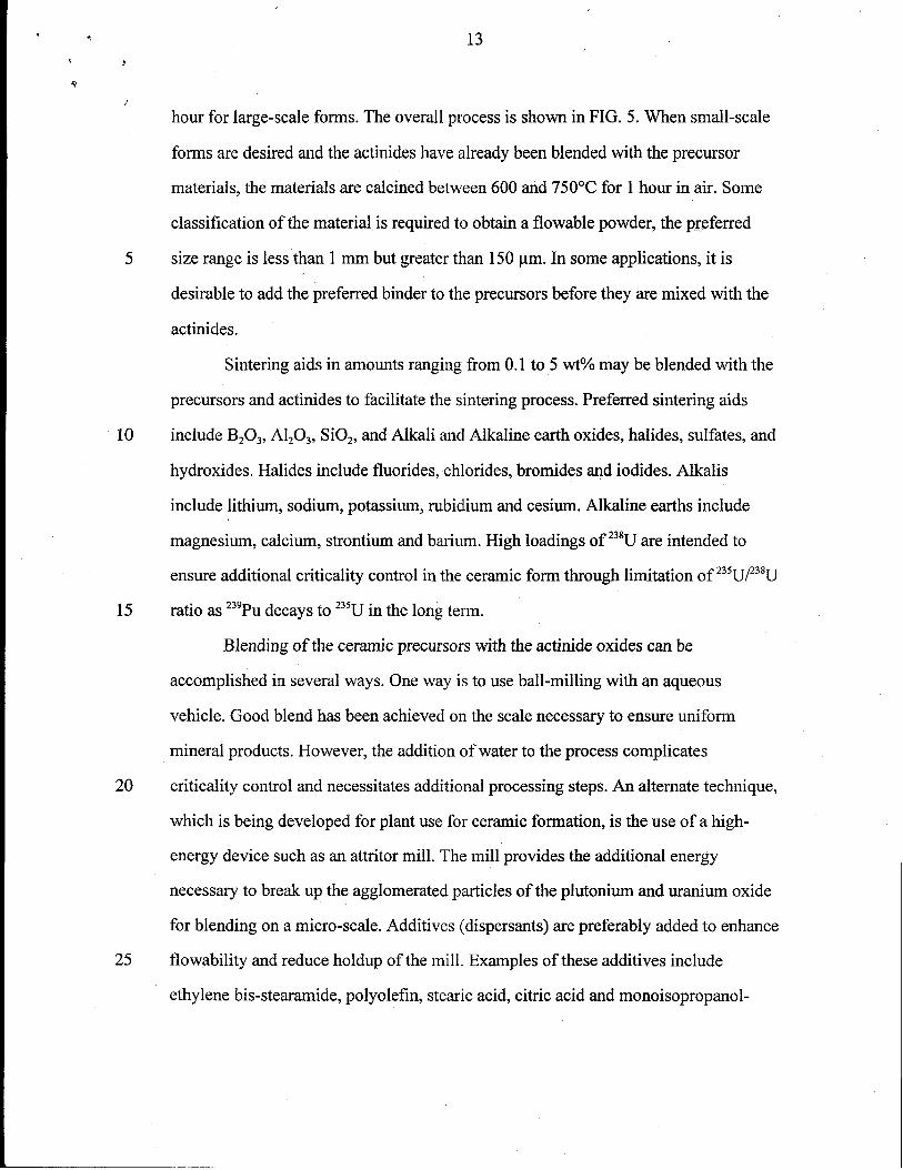
hour for large-scale forms. The overall process is shown in FIG. 5. When small-scale
forms are desired and the actinides have already been blended with the precursor
materials, the materials are calcined between 600 and 750°C for 1 hour in air. Some
classification of the material is required to obtain a flowable powder, the preferred
5 size range is less than 1 mm but greater than 150 pm. In some applications, it is
desirable to add the preferred binder to the precursors before they are mixed with the
actinides.
Sintering aids in amounts ranging from 0.1 to 5 wt% may be blended with the
precursors and actinides to facilitate the sintering process. Preferred sintering aids
10 include B20J, AIzO~, SiOz, and Alkali and Alkaline earth oxides, halides, suIfates, and
hydroxides. Halides include fluorides, chlorides, bromides and iodides. Alkalis
include lithium, sodium, potassium, rubidium and cesiurn. Alkaline earths include
magnesium, calcium, strontium and barium. High loadings of 238Uare intended to
ensure additional criticality control in the ceramic form through limitation of 235U/23gU
15 ratio as 239Pudecays to 235Uin the long term.
Blending of the ceramic precursors with the actinide oxides can be
accomplished in several ways. One way is to use ball-milling with an aqueous
vehicle. Good blend has been achieved on the scale necessary to ensure uniform
mineral products. However, the addition of water to the process complicates
20 criticality control and necessitates additional processing steps. An alternate technique,
which is being developed for plant use for ceramic formation, is the use of a high-
energy device such as an attritor mill. The mill provides the additional energy
necessary to breakup the agglomerated particles of the plutonium and uranium oxide
for blending on a micro-scale. Additives (dispersants) are preferably added to enhance
25 flowability and reduce holdup of the mill. Examples of these additives include
ethylene bis-stearamide, polyolefin, stearic acid, citric acid and monoisopropanol-

14
5
10
20
25
amine.
Two methods of mixing the precursors with the actinides have been tested.
The first method involves first grinding the actinides and then mixing in the
precursors in a separate attritor mill. The second method utilizes one large mill to
grind the actinides and mix them with precursor material at the same time. In a one-
gallon high-speed attritor mill, which has been used for most of the testing, agitator
speeds range from 600 to 1100 rpm with a preferred running speed of approximately
950 rpm. Acceptable milling media size is two to five-millimeter spheres, preferably
five-millimeter media. The milling media is zirconia, aluminum oxide, depleted
uranium, stainless steeI, or ceramic, preferably stabilized zirconia, most preferably
zirconia stabilized with yttria. To scale up the process for use in larger attritor mills,
the parameter to be held constant is the tip speed. For a given rpm, the edge of the
agitator arm in the larger mill will be moving faster than in the smaller mill. This will
affect how the powder is worked. Thus it is important that the tip speed of the agitator
arms is matched when using larger mills. Milling and/or mixing times range from
three to twelve minutes with a preferred run time of five minutes. Generally, the run
time is increased by two to three minutes if the material is being milled and mixed in
the same attritor. The five-minute run time has been used for batches ranging from
five hundred grams to one thousand grams of material. Higher milling rpms will
generally result in greater uniformity of particle size and shorter run times. Milling
and mixing times need to be sufficiently long to achieve the desired particle size and
for a homogeneous mix. Excessively long mixing times may result in demixing,
wherein the constituents begin to separate. Each time the attritor is run a small
amount of dispersant is added to the powder to maintain powder flowability. The
amount is dependent upon the type used, but ranges from one-tenth of a percent to
five percent based on the batch weight, preferably in the range of 0.5 to 3V0.

Preferably, either one-half weight percent of ethylene bis-stearamide or three weight
percent ofpolyolefin areused. Theadditive isusedin thesame amounts whether the
actinides are milled independently and then mixed, or co-milled and mixed.
The mixture is then granulated to facilitate uniform flow into a press die set.
5 During the granulation step, binder and lubricant materials are added. Acceptable
granules have been formed with hydroxy-propyl methylcellulose and/or polyethylene
glycol added in a water emulsion as the binder. The preferred binder will have the
following proportions: 0.5 to 2 wt% hydroxy-propyl methylcellulose, 0.5 to 5 wt%
polyethylene glycol, and 0.5 to 10 wt% water. The preferred lubricants include
10 ethylene bis-stearamide and polyolefin. Granulation is preferred because of the
tendency for the finely milled blend to clump, and the milled blend is difficult to
meter and transfer to the press system. In addition, handling of such finely milled
powder presents the possibility of excess dusting when the milled and blended
powder is removed from the contained powder preparation unit. Once granulated, the
15 blended milled product is easily transferred, metered, and stored and is relatively
dust-less during handling. A “V” shell blender, a blade granulator, a fluid bed, a pin
mixer, a slant double cone blender, and a roll compactor have been used for
granulation and have all been shown to meet the flowability criteria. In some
applications, lubricants are not added to the powders and are instead applied to the die
20 walls. Studies have shown that ten weight percent oleic acid added to acetone is an
acceptable external lubricant.
The granulated mixture is then poured into a press die set and cold pressed at a
pressure range of 1,000-20,000 psi, preferably at 2,000 psi for large-scale ceramic
forms. This greatly minimizes die wear and press operation difficulties. However,
25 due to the low pressing force, the resulting green ceramic materials can be relatively
fragile until they are sintered, and some care should be taken in handling. Since the
.’ .“
>
16
5
10
20
25
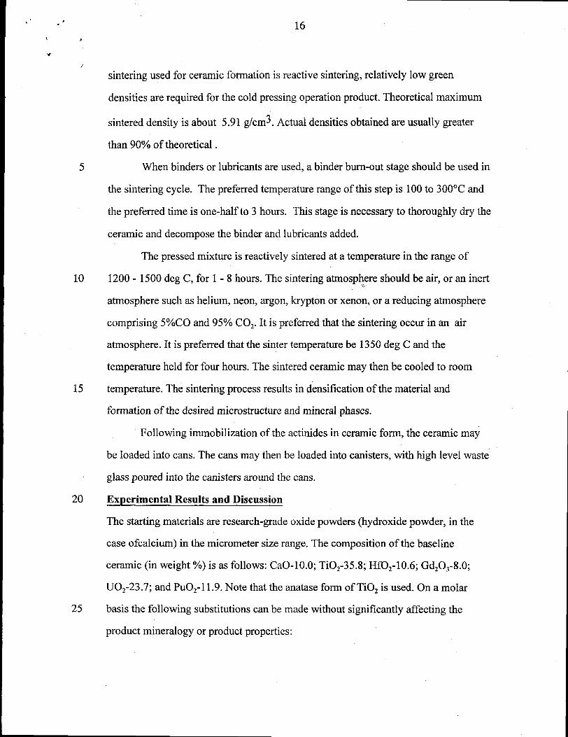
sintering used for ceramic formation is reactive sintering, relatively low green
densities are required for the cold pressing operation product. Theoretical maximum
sintered density is about 5.91 g/cm3. Actual densities obtained are usually greater
than 90°A of theoretical.
When binders or lubricants are used, a binder burn-out stage should be used in
the sintering cycle. The preferred temperature range of this step is 100 to 300”C and
the preferred time is one-half to 3 hours. This stage is necessary to thoroughly dry the
ceramic and decompose the binder and lubricants added.
The pressed mixture is reactively sintered at a temperature in the range of
1200-1500 deg C, for 1-8 hours. The sintering atmosphere should be air, or an inert..-
atmosphere such as helium, neon, argon, krypton or xenon, or a reducing atmosphere
comprising 5°/oC0 and 95°/0 COZ. It is preferred that the sintering occur in an air
atmosphere. It is preferred that the sinter temperature be 1350 deg C and the
temperature held for four hours. The sintered ceramic may then be cooled to room
temperature. The sintering process results in densification of the material and
formation of the desired microstructure and mineral phases.
Following immobilization of the actinides in ceramic form, the ceramic may
be loaded into cans. The cans may then be loaded into canisters, with high level waste-
glass poured into the canisters around the cans.
Experimental Results and Discussion
The starting materials are research-grade oxide powders (hydroxide powder, in the
case ofcalcium) in the micrometer size range. The composition of the baseline
ceramic (in weight ‘A) is as follows: CaO-1 0.0; TiOz-35.8; Hf02-10.6; Gd20~-8.0;
U02-23.7; and PU02-1 1.9. Note that the anatase form of TiOz is used. On a molar
basis the following substitutions can be made without significantly affecting the
product mineralogy or product properties:

*
●
17
PU02 can be replaced with Ce02, UO,, a.dor Th02
UOZ can be replaced with PU02, CeOz and/or ThOz
5
HfOz can be replaced with ZrOz
GdzO~ can be replaced with Sm20~.
In small-scale, form development testing, these powders are wet-mixed for
one hour using a ball mill with A1203 or Zr02 grinding media and deionized water.
They are then separated by sieving and flushing with water and are dried overnight at
about 90 deg C in air. The dried powder is then size-reduced and calcined at 750 deg
C for one hour in either argon or air atmosphere. It is then cold-pressed in a steel die
10 at about 11,400 psi into cylindrical pellets, typically 1.27 cm in diameter, with length-
to-diarneter ratio less than one. Between pressings, the steel die is coated with a thin
layer of about 10 wt YOoleic acid in acetone as a die lubricant. No binders are used.
The pellets are placed on platinum foil (recent practice) or on a thin layer of alumina
or zirconia powder (earlier practice) and are then reaction-sintered in argon
15 atmosphere (commercial puri~) at 1350 deg C for 4 hours. Some samples are fired in
an air atmosphere or 5°/0CO in a balance of COZ. The fired densities are routinely
evaluated using weight and geometric size, and are typically 90°/0 of the calculated
theoretical maximum density or higher. Phase composition is routinely evaluated by
X-ray diffraction analysis (XRD) and scanning electron microscopy (SEM)-energy
20 dispersive spectrometry (EDS). Detailed analysis by electron microprobe is
pefiorrned on select samples.
In large-scale, production form testing, the precursor powders are wet-mixed
for a minimum of two hours using a ball mill with Zr02 grinding media and deionized
water. They are then separated by sieving and flushing with water and are dried
25 overnight at about 105 deg C in air. The dried powder is then size-reduced and
calcined at 750 deg C for one hour in an air atmosphere. The calcined precursors are
‘ J
‘a
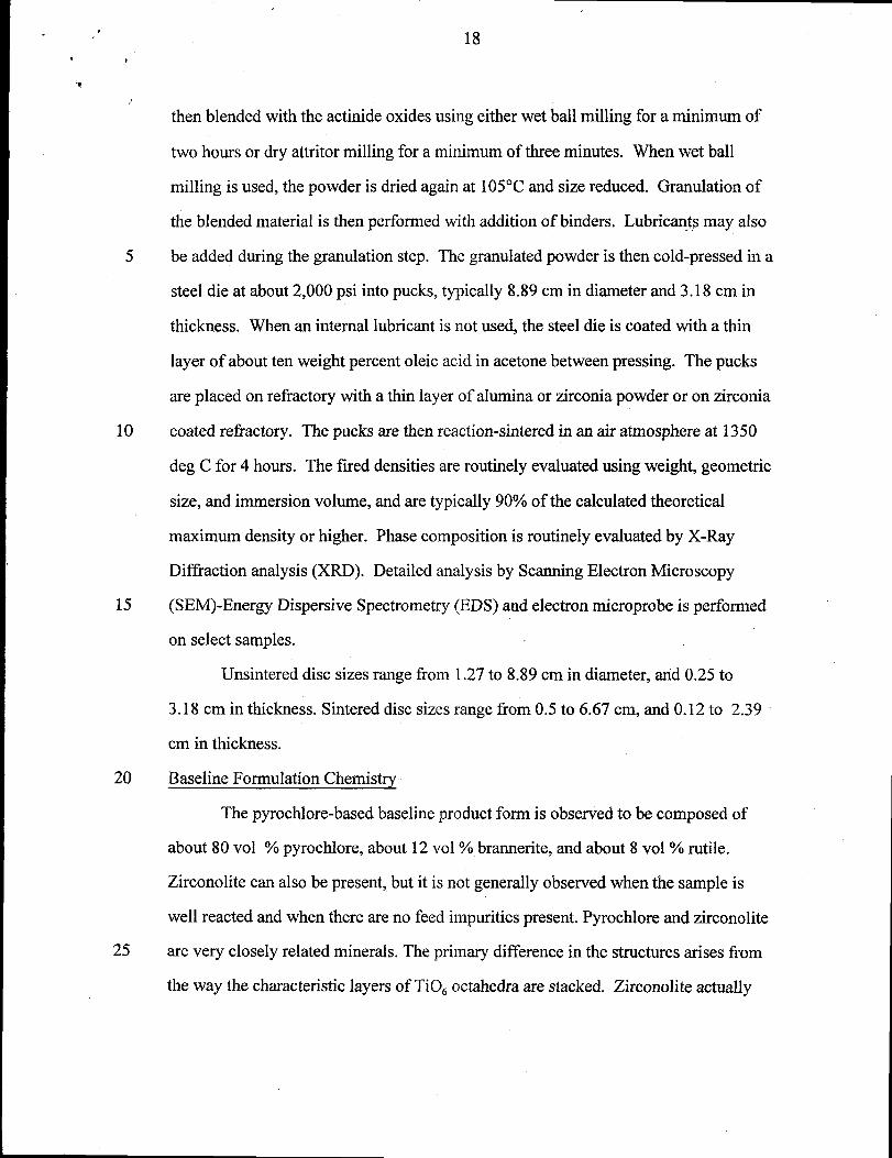
/then blended with the actinide oxides using either wet ball milling for a minimum of
5
10
15
20
25
two hours or dry attritor milling for a minimum of three minutes. When wet ball
milling is used, the powder is dried again at 105°C and size reduced. Granulation of
the blended material is then performed with addition of binders. Lubricants may also
be added during the granulation step. The granulated powder is then cold-pressed in a
steel die at about 2,000 psi into pucks, typically 8.89 cm in diameter and 3.18 cm in
thickness. When an internal lubricant is not used, the steel die is coated with a thin
layer of about ten weight percent oleic acid in acetone between pressing. The pucks
are placed on refractory with a thin layer of alumina or zirconia powder or on zirconia
coated refractory. The pucks are then reaction-sintered in an air atmosphere at 1350
deg C for 4 hours. The fired densities are routinely evaluated using weight, geometric
size, and immersion volume, and are typically 90°/0 of the calculated theoretical
maximum density or higher. Phase composition is routinely evaluated by X-Ray
Diffraction analysis (XRD). Detailed analysis by Scanning Electron Microscopy
(SEM)-Energy Dispersive Spectrometry (EDS) and electron microprobe is performed
on select samples.
Unsintered disc sizes range from 1.27 to 8.89 cm in diameter, and 0.25 to
3.18 cm in thickness. Sintered disc sizes range from 0.5 to 6.67 cm, and 0.12 to 2.39-
cm in thickness.
Baseline Formulation Chemistry
The pyrochlore-based baseline product form is observed to be composed of
about 80 VOI 0/0pyrochlore, about 12 vol 0/0brannerite, and about 8 VOI0/0rutile.
Zirconolite can also be present, but it is not generally observed when the sample is
well reacted and when there are no feed impurities present. Pyrochlore and zirconolite
are very closely related minerals. The primary difference in the structures arises from
the way the characteristic layers of TiOc octahedra are stacked. Zirconolite actually
19
5
10
15
20
25
has several structural polytypes that also differ in the way the characteristic layers are
stacked: zirconolite-2M, zirconolite-3T, and zirconolite-4M (yolymygnite) to name
those that have actually been observed in this ceramic form. The number corresponds
to the number of layers before the stacking repeats itself and the letter stands for the-
crystal symmetry, M for monoclinic and T for trigonal. When the layers are aligned in
a body-centered fashion, the pyrochlore phase is formed.
The phase relationship between pyrochlore and zirconolite and its polytypes is
one important part of defining the baseline formulation. To depict the phase
relationships, a pseudo-ternary diagram is given in Figure 2. The end points are
zirconolite (CaZrTi20T or CaHffizOT), Pu-pyrochlore (CaPuTizOT or its surrogate
CaCeTizOT), and U-pyrochlore (CaUTizOT). The open points are data from Cc-loaded
samples, and the solid points are data from the Pu-loaded samples. The squares
contain Hf and Zr and the diamonds contain U only. The circles are data from the Zr-
loaded samples, and the triangles are from the Hf-loaded samples. Many of the
samples contain Gd, which had to be factored out in order to depict all the data on one
ternary diagram. For simplicity the Gd was all assumed to be entirely on the Ca site,
which is accurate in many cases. As a result of this assumption, Figure 2 is more
correctly described as a ternary plot consisting of the three components, (1) Pu or Ce,
(2) Hf or Zr, and (3) U. The baseline composition in this diagram is at approximately
0.49 units of U, 0.25 units of Pu, and 0.26 units of Hf.
Figure 2 clearly shows that the equilibrium phase behavior of Hf and Zr and of
Ce and Pu are for all practical purposes indistinguishable. Closer inspection reveals
that the equilibrium phase behavior of U is also identical to that of Ce and Pu, i.e. the
pyrochlore phase boundary is independent of the total U, Pu, and Ce composition.
Note that with a comparable offset adjustment in the U-loading, the Pu-loading in the
form can be adjusted anywhere from Oto about 32% without appreciably changing

20.,
5
10
15
the mineralogy in the baseline form. The regime above 0.7 units of Ce, Pu, and U is
the pyrochlore single-phase regime. The region above about 0.8 units of Hf and Zr is
the single phase zirconolite regime (-2M). There is some scatter in the zirconolite
boundary. This is due at least in part to a temperature effect. At around 1400 deg C,
the boundary appears to be closer to about 0.75 formula units, and at around 1200 deg
C, the boundary appears to be closer to about 0.85 formula units. An intermediate
phase generalIy occurs at about 0.5 formula units of Hf or Zr. This is the zirconolite-
4M phase. This phase is generally not observed in samples with impurities.
Microprobe analyses on a number of samples have been averaged to give the
nominal atomic compositions of the primary phases in the ceramic form. The nominal
atomic compositions are given in Table I. For zirconolite and pyrochlore, the total
metal composition is normalized to 4. For brannerite, the total metal composition is
normalized to 3, and for rutile and actinide oxide, it is normalized to unity. The
corresponding amount of oxygen based on the assumed oxidation states shown is
given in the O equivalent column. In the ideal structures, the oxygen equivalents for
pyrochlore, zirconolite, brannerite, rutile, and actinide oxide are 7,7,6,2, and 2,
respectively.

21●
‘n
/
Table I.
Elemental compositions in baseline form
5 One of the interesting features in the compositions shown in Table I is that
although the phase boundaries appear to be the same for the use of either UOZ or PuOZ
in the formulation, the elemental partitioning between the phases is different. Notice
that U is enriched relative to Pu in the brannerite phase and depleted relative to Pu in
the zirconolite phase. These enriched and depleted relationships are based on.
10 comparison to the approximate 2-to-1 ratio of U-to-Pu in the dominant pyrochlore
phase, which corresponds to the U-to-Pu ratio in the ceramic composition as a whole.
Actinide Oxide Dissolution Kinetics
Dissolution of “high-fired” PuOZ or Pu02/U02 into the ceramic form seems to
15 be affected significantly by temperature, process impurities, and thoroughness of
mixing, and to a lesser extent by the relative abundance of the primary phases. Note
that all “high-fired” PuOZ used in these tests was heated to 1000 deg C for 4 hours in
an air atmosphere and all the “high-fired” PuOZAJOZwas heated to 950 deg C for 2
hours in an argon atmosphere.

*
, ,
.,
22
In earlier formulation work, a zirconolite-rich formulation was being
developed, and data on actinide dissolution kinetics was obtained for this formulation.
In addition to the matrix phase of zirconolite, the form contained Ba-hollandite, rutile,
and pyrochlore. In this set of experiments performed at LLNL, the “high-fired” PuOZ
5 was sieved through a 600 mesh sieve (i.e., the particles were less than 20 microns
diameter) and the precursors were then dry mixed by hand in a V-shaped mixer. A
half dozen pellets were pressed at between 30 and 80 MPa and fired at 1300 deg C for
4 hours. After the first firing, the product densities varied from about 89 to 96% of the
theoretical maximum (4.9 g/cm3). The samples were then separated into 3 pairs and
10 fired at 1300, 1350, or 1400 deg C for 4 hours. One of each pair was then subjected to
a simulated DWPF thermal cycle. Results of the thermal treatment tests are discussed
later. All of the product pellets were analyzed using the SEM/microprobe. The pellets
with the 1300 deg C final firing temperature had large chunks of “unreacted” PuOZ up
to about 20 microns in diameter. The PU02 is termed “unreacted” in this case since it
15 was found to be essentially pure PuOZ. The pellets fired at 1350 deg C had a small
amount of “reacted” PuOZ, typically 3 microns in diameter or less. The PuOZ is
termed “reacted” in this case because it was found to contain significant and
consistent amounts of Gd and Zr. Only one “reacted” PU02 grain barely larger than 2
microns diameter was found in the sample with the final firing temperature of 1400
20 deg C. From these data it is clear that 1300 deg C is an inadequate temperature to
achieve PuOZ dissolution into the zirconolite-rich ceramic form. However, 4 hours at
1350 deg C appears to be adequate time and temperature to achieve dissolution of
PuOZ particles up to about 20 microns in diameter into the zirconolite-rich ceramic
matrix. Apparently, the reaction kinetics increase significantly between 1300 and
25 1350 deg C. It is not known for certain, but the significant increase in reaction
kinetics is believed to be the result of a minor liquid phase that forms at temperatures

23
greater than about 1325 deg C.
The current baseline formulation is pyrochlore-rich not zirconolite-rich. In
more recent work performed at ANSTO, a mixture of “high-fired” PuOZAJOZ(1 part
Pu per 2 parts U) was dry-milled with ceramic precursors, pressed into pellets at
about 90 MPa and fired at temperatures ranging from 1275 to 1400 deg C for 4 hours.
The PuOz/UOz feed materiaI was composed of a number of large agglomerates greater
than 10 microns but less than about 20 microns in diameter. Most firings were
performed in an argon atmosphere, but some were performed in air. The results
suggest that the particle size requirements for the pyro~hlore-based form are less
stringent than for the previously mentioned zirconolite-rich form. Enhanced
dissolution was generally observed as the temperature was increased, but even at
1300 deg C the PuOz/U02 dissolution was satisfactory, much better than in the
previously mentioned work on the zirconolite-rich formulation. All residual
Pu02/UOz in the pyrochlore-rich ceramic form fell into the category of “reacted,” i.e.,
it contained significant and relatively consistent amounts of Gd and Hf.
Two other important generaI observations have been made. First, the residual
“reacted” PuOZRJ02 in the pyrochlore-rich formulation is essentially always observed
to be encapsulated within the brannerite grains. This indicates that by decreasing the
amount of the brannerite component in the formulation, enhanced PuOZ and/or U02
dissolution can be obtained. Second, feed impurities such as silica enhance PuOZ
and/or UOZ dissolution considerably. Since feed impurities can also aid densiflcation,
their presence in limited quantities can be advantageous to the ceramic form. Note
that although a reactive “low-fired” PU02 was never tested, it has been found that a
sufficiently small PU02 and/or U02 particle size and good mixing are more than
sufficient to achieve dissolution of PU02 and/or UOZ into the ceramic form. Therefore,
any enhanced dissolution into the ceramic form that could be gained by using “low-

,
‘f
243
/
fired” PuOJ is not required.
Feed Impurity Tolerances
Tolerance of the ceramic form to the range of feed impurities expected is an
5 important part of making the ceramic form a viable and attractive candidate for Pu
disposition. A relatively large amount of work was conducted in this area at LLNL,
SRS, and ANSTO. A set of 10 Pu-sample compositions and 10 Ce-sarnple
compositions were prepared according to the general procedure described in the
experimental section. Pu-sample compositions are given in Table II. Composition A-O
10 is the baseline ceramic form. Compositions A-1 to A-6 correspond to various general
categories of feed material that are expected. A-1 corresponds to typical impure
oxides. Nominally about 5 metric ton (MT) of currently declared U.S. excess Pu falls
into this category. A-2 corresponds to the composition of Pu from the Zero Power
Physics Reactor (ZPPR) plates. Nominally about 3 MT of current excess Pu falls into
15 this category. A-3 corresponds to the composition of atypical impure metal.
Nominally about 2 MT of current excess Pu falls into this category. A-4 corresponds
to the composition of atypical clean metal. Nominally about 1 MT of current excess
Pu falls into this category. A-5 corresponds to the composition of U/Pu oxides.
Nominally about 1 MT of current excess Pu falls into this category. A-6 corresponds
20 to the composition of Pu alloys. Nominally about 1 MT of current excess Pu falls
into this category. A-7 is an overall estimated average composition for the 17 MT
excess Pu case. A-8 is an estimated most extreme case. A-9 is an intermediate case
between A-7 and A-8 that corresponds roughly to one of the extreme compositions
tested in the competing glass formulation work.

.
t *25
Table IL
Compositions of samples fabricated in the feed impurity tests.
(Totals may not exactly equal 100% because of rounding)
5
EWto
ase ee at<
0.22
0.23 0.02
1.2’/ 0.14
0.14
(.).02
().()9
-r
9.85 9.83
35.50 35.43
I
0.11 1.04
0.46 ().18
A-’/ A-8 A-9
Wt% Wt% Wt Vo

26
/
Sample preparation and characterization work was shared among the various
participating sites. Samples A-1 to A-6 were generally prepared only at one site,
whereas samples A-O, A-7, A-8, and A-9 were prepared at two or three different sites.
5 At least one Cc-sample and one Pu-sarnple of each composition were successfi.dly
prepared. All of the Ce-sarnples and most of the Pu-samples have since been
characterized to determine the product phase assemblages. All of the samples reacted
well and formed pyrochlore as the dominant phase, even sample A-8 which had
% total impurities in the product. Several trends were observed. Si could not be
o incorporated significantly into any of the primary ceramic phases. Si02 forms a
separate glassy phase that contains significant amounts of Ca, Al, Ti, and other
13 Wt
impurities but little or no Pu or U. Excess amounts of Al in the feed also increase the
likelihood of the glass phase formation. The same effect seems to be observed for P.
PzOj was not intentionally added to the form, but was found to be present at about
5 200 ppm in the Ti02 starting material. PZ05 forms a separate phase (pres~ably
whitlockite) that is rich in Ca and P. In general, all other impurities were either
vaporized or accommodated into at least one of the primary ceramic phases.
Compositions that were low in impurities produced ceramics that were for the most
part rich in brannerite and lean in zirconolite, and compositions that were rich in
o impurities produced ceramics that were for the most part lean in brannerite and rich in

. .
1 ,27
‘t
)
zirconolite. As mentioned earlier, the impurities seem to enhance the reaction kinetics
considerably. Cornpositions with the highest impurity levels had the least amount of
actinide oxide in the product, as low as 0.04 vol 0/0,and compositions with the lowest
impurity levels had the greatest amount of actinide oxide in the product, as high as 0.6
5 vol O/O.Based on image analysis of the SEM images obtained, the compositional
range observed in the suite of impurities tests was as follows: pyrochlore-62 to
90 vol VO,brannerite-O to 22 vol %, zirconolite-O to 25 vol %, rutile-O to 16 vol Yo,
actinide oxide-O.004 to 0.6 vol 0/0,and silicate glass-O to 6 vol 0/0as shown in Table
III.
10 Note that these samples were fired at 1350 deg C for 4 hours in an argon
atmosphere. SampIe compositions with CeOz used 0.634 times the PuOZ mass listed
in order to keep the molar compositions the same.
TABLE III
Product Mineralogy
15
data were used to generate the preliminary partitioning coefficients given in Table IV.
As is readily seen, the more common impurities, namely Al, Cr, Fe, Ni, Ga, and Mg,

. .
‘t.
‘f
28
5
10
partition preferentially into zirconolite. A few impurities partition preferentially into
the pyrochlore phase, namely Mo, Ta, and W. Na, K, and Zn tend to vaporize and/or
to partition into the silica-rich glassy phase, but the little that remains in the p~mary
phases does seem to partition selectively. Some data are also given for the relative
partitioning of impurities into brannerite compared to pyrochlore. With the possible
exception of Ni and Zn, the impurities do not seem to partition significantly into the
brannerite phase.
Table IV.
Approximate partitioning coefficients for various impurities.
Mement XzirconolitelXpyrochl ore XbranneritelXpyrochlore
Al 16 .
Cr I 15 I---
I
>juI
---I
Mo 0.10 ().20
Na <0.1 0.2
NI 1.5 2
la <().1 <0. ]
w ().()2() ---
The partitioning coefficient is given as the mole fraction of the element in the phase
of interest divided by the mole fraction of the element in the pyrochlore phase

29
5
The maximum impurity levels demonstrated are as shown in Table V.
Table V
Maximum Impurity Levels Demonstrated
Impurity Product Concentration (wt %) Equivalent Feed Concentration (wt %)
AlzO~ 10.0 48.3
BzO~ 1.0 7.8
BaO 2.3 16.3
CaClz 2.19 15.8
CaFz 10.0 48.3
CaO 10.0 48.3
CrzO~ 10.0 48.3
CU20 10.0 48.3
F~Oq 10.0 48.3
Ga,O~ 15.3 60.2
K20 1.05 8.9
MgO 10.0 48.3
MnOz 10.0 48.3
MoOS 10.9 50.7
NazO 0.47 4.3
Nb20~ 10.7 50.2
NiO 10.0 48.3
P205 5.1 31.0
PbO 0.5 4.2
SiOz 1.50 12.7
SnOz 4.1 26.6
TazO~ 13.0 55.8
W03 16.4 62.3
ZnO 10.0 48.3
MaX.Tot. 13.0 55.7
Max. Tot. is the maximum combined total of impurities that was tested. Product
concentration is the concentration of the impurity in the immobilized product.
Equivalent feed concentration is the equivalent feed concentration of the impurity in
30
5
10
15
20
25
the PuOZ feed.
Stability with Respect to the DWPF Pour
Since it is planned that cans containing the ceramic will be enveloped in
molten glass during the glass pouring operation at the DWPF, it is important to know
that the ceramic will remain stable during this process. Tests in this area fell into two
basic areas, evaluation of potential mineralogical and compositional changes during
the heating and the slow cool-down, and evaluation of potential cracking during the
rapid heat-up.
The heating and slow cool-down process was simulated by heating the product
forms to between 1000 and 1200 deg C and cooling at between 1 and 2 deg C per
minute. In every case, no mineralogical change was observed. Phase compositions
before and after thermal treatment were analyzed by electron microprobe or
quantitative EDS analysis. In every case, there was little or no compositional change.
Any smaIl compositional differences observed were well within the statistical
variations expected. Compositions before and after one of the thermal treatment tests
are given in TabIe VI. In this particular test, the previously mentioned zirconolite-rich
samples were used. These were the samples with the final firing temperature of 1350
deg C. One of the two samples was then subjected to a simulated DWPF thermal
heating and cooling cycle: heat to 1000 deg C, hold for 15 minutes, cool to 500 deg C
at 2 deg C per minute, then cool to ambient at 1 deg C per minute or slower. There
were five phases in the sample: zirconolite, pyrochlore, rutile, hollandite, and
“reacted” PuOZ. Only the compositions for the Pu-bearing phases are given in Table
IV. Under the column of DWPF, a “no” means that the data are from the sample that
was not subjected to the simulated DWPF thermal cycle and a “yes” means that the
data are from the sample that was subjected to the simulated DWPF thermal cycle.
Note that the compositional analyses are surprisingly close, even for the “reacted”
5
10
31
PU02.
A test was also performed in which molten DWPF-type glass was heated to
about 1I00 deg C and was then poured directly onto bare non-radioactive ceramic
pellets to determine qualitatively how badly the ceramic would crack because of the
thermal shock. In short, the cracking was minimal. Out of 7 pellets, ranging from 2.5
to 4 cm in diameter, only one pellet cracked into two separate pieces. All the other
pellets remained intact, with little or no observed cracking.
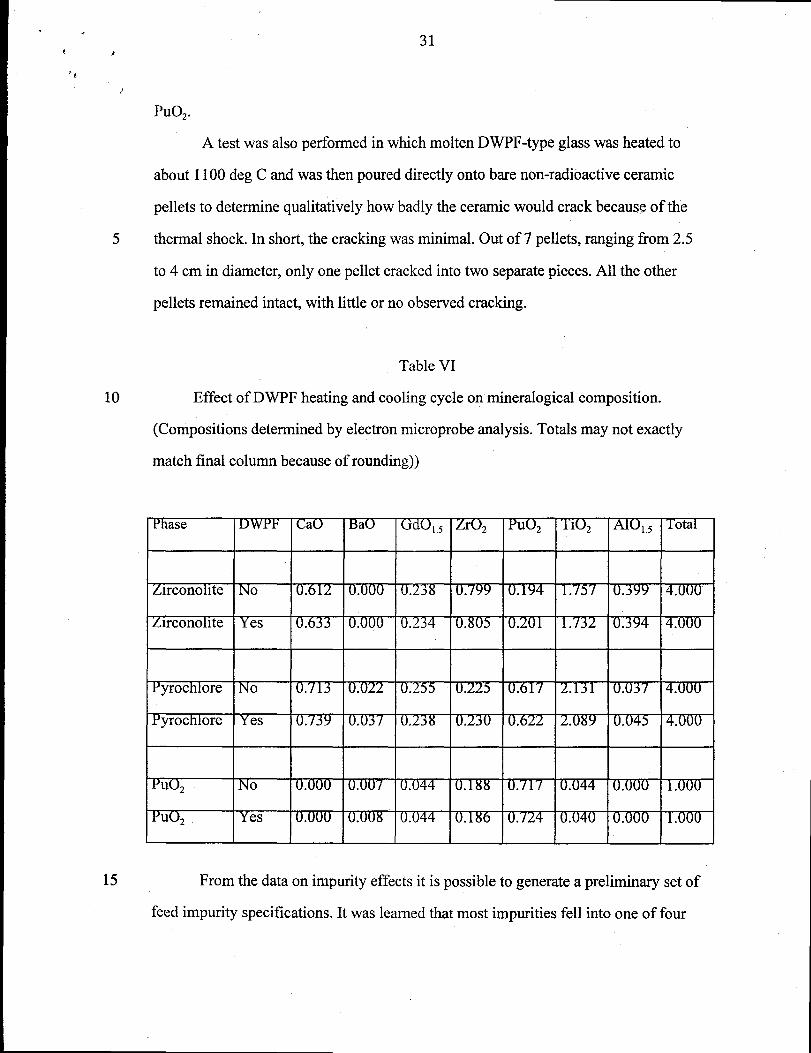
Table VI
Effect of DWPF heating and cooling cycle on mineralogical composition.
(Compositions determined by electron microprobe analysis. Totals may not exactly
match final column because of rounding))
15 From the data on impurity effects it is possible to generate a preliminary set of
feed impurity specifications. It was learned that most impurities fell into one of four
I
32
5
10
15
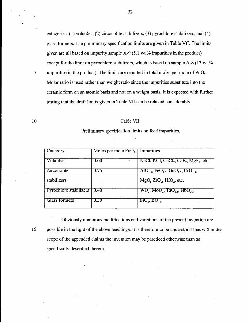
categories: (1) volatiles, (2) zirconolite stabilizers, (3) pyrochlore stabilizers, and (4)
glass formers. The preliminary specification limits are given in Table VII. The limits
given are all based on impurity sample A-9 (5.1 wt VOimpurities in the product)
except for the limit on pyrochlore stabilizers, which is based on sample A-8 (13 wt 0/0-
impurities in the product). The limits are reported in total moles per mole of PU02.
Molar ratio is used rather than weight ratio since the impurities substitute into the
ceramic form on an atomic basis and not on a weight basis. It is expected with further
testing that the draft limits given in Table VII can be relaxed considerably.
Table VII.
Preliminary specification limits on feed impurities.
Category
Wolatlles
Arconohte
stabilizers
l?yrochlore stabdlzers
Glass tormers
Moles per mole PU02
(.).60
. 15
().40
().30
Obviously numerous modifications and variations of the present invention are
possible in the light of the above teachings. It is therefore to be understood that within the
scope of the appended claims the invention maybe practiced otherwise than as
specifically described therein.

.
,
‘*
PROCESS FOR MAKING A CERAMIC COMPOSITION FOR
IMMOBILIZATION OF ACTINIDES
ABSTRACT OF THE DISCLOSURE
Disclosed is a process for making a ceramic composition for the immobilization
of actinides, particularly uranium and plutonium. The ceramic is a titanate
material comprising pyrochlore, brannerite and rutile. The process comprises
oxidizing the actinides, milling the oxides to a powder, blending them with
ceramic precursors, cold pressing the blend and sintering the pressed material.

1
T = 1350C“CaTi03”
CaOPyrochiore > Zirconolite + Brannerite
o
“H AnTi20i’
Hf02 O 25 50 75 100 AnOZ
FIG. 1Depiction of the processing regime.

2
Zr or Hf“Ca(Zr,Hf)Ti20#
Oyb I
P+ U only
❑ Hf, Zr, & Ce
P
Pu or Ce P“Ca(Pu,Ce)Ti20+’
o 25 50 75 100
FIG. 2Phase boundaries in the system Ca(Hf,Zr)TizOy-Ca(Pu,Ce)TizOT-
CaUTizOT.

3
Actinides
#l—F/_, ~~idizing
I
Lb
Halideremoval ➤
Actinide Oxides
FIG. 3Flow Diagram of Actinide Oxidation Process

>
*J ‘ .*
‘9,,’
Dis ersant
3
ActinideOxides
4
Dispersant
3
Milling “—+
Binder and/or Lubricant Additives
Granulating I
+
Pressing
BinderBurn-out
=4Sintering
Sintered
FIG. 4Flow Diagram of Immobilization Process
(Actinide Oxides)

. .5
neutron absorbers,titanium oxide, calciumhydroxide
[
L’=1’— Drying
I
I
*
rCalciningb
CeramicPrecursors
FIG. 5Flow Diagram of Ceramic Precursor Fabrication