pws series air/water heat exchangers - … maximum permissible operating pressure is 10 bar. pws...
TRANSCRIPT
ELECTRO-TECHNOLOGY FOR INDUSTRY
PWS Series Air/Water Heat Exchangers
Safety for man, machine and the environment®
Installation, Operation and Service Manual


TABLE OF CONTENTS
SECTION 1: HOW TO USE THIS MANUAL ..........1
SECTION 2: RECEIVING INSPECTION ................22.1 Unpacking ...........................................................22.2 Included Items ...................................................22.3 Review of ID Plate ...............................................2
SECTION 3: HANDLING ......................................33.1 Transporting .......................................................33.2 Storage ................................................................3
SECTION 4: INSTALLATION ................................34.1 Pre-installation testing ......................................34.2 Installation onto the electrical panel ................34.3 Power connection ...............................................44.4 Cooling Water Connection .................................44.5 Condensation Water Connection ......................44.6 Door Contact .......................................................5
SECTION 5: OPERATING CONDITIONS ..............65.1 Requirements .....................................................65.2 Theory of Operation ...........................................6
SECTION 6: UNIT START-UP ...............................76.1 General ................................................................76.2 Setting the Operating Parameters ....................76.2.1 Units with Water (Solenoid) Valve and Thermostat ...............................................76.2.2 Units without Water Valve and Thermostat ..7
SECTION 7: MAINTENANCE ...............................8
SECTION 8: TROUBLESHOOTING ......................8
SECTION 9: DESIGN DATA ..................................89.1 Water Quality Notes ...........................................89.2 SCCR Determination .........................................10
SECTION 10: WARRANTY INFORMATION ...... 12
PWS Series Air/Water Heat Exchangers
1
SECTION 1: HOW TO USE THIS MANUAL
This manual contains information on the installation and operation of PWS Series bolt-on cooling units intended to be door and side mounted on electrical panels.
These devices are designed to dissipate heat from sealed electrical panel enclosures and housings. The temperature of the cooling liquid supplied to the air/water heat exchanger must be at least 10° C colder than the heat exchanger inlet air temperature in order to ensure that the unit function correctly.
Conventions used:
Hint: A hint contains additional information on the action or instruction being described
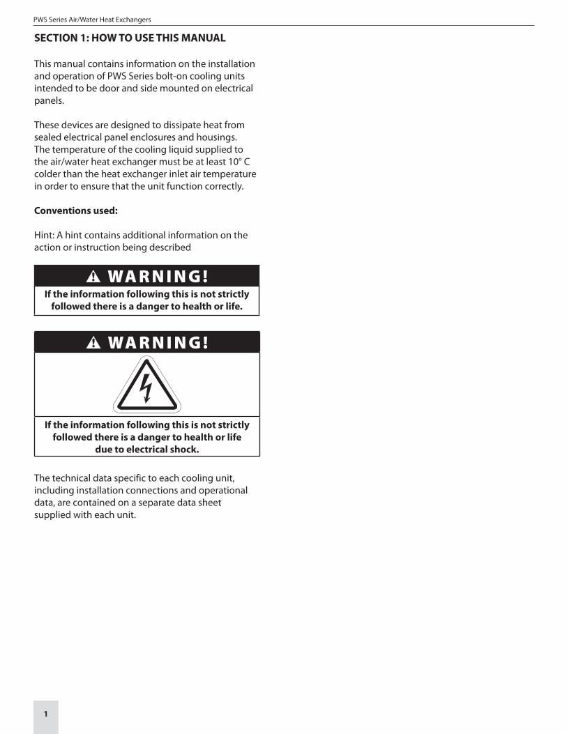
WA R N I N G !If the information following this is not strictly
followed there is a danger to health or life.
WA R N I N G !
If the information following this is not strictly followed there is a danger to health or life
due to electrical shock.
The technical data specific to each cooling unit, including installation connections and operational data, are contained on a separate data sheet supplied with each unit.
2
SECTION 2: RECEIVING INSPECTION
2.1 UnpackingPrior to and during unpacking the cooling unit, visually inspect it to determine if any damage has occurred during shipping. Make sure that it does not contain any loose components. Before discarding any packaging materials: Look for loose parts, dented or scratched panels or fluids.
If any damage is noted it shall be reported immediately to the delivering carrier and a claim should be filed with them. Pfannenberg cannot accept responsibility for freight damage that may occur; we will assist you in any way possible if the need arises to file a claim.
In case of a warranty claim, the following information is required: exact details of the fault (including photographs, if possible), the cooling unit part number and serial number are required.
WA R N I N G !Burrs caused by production may be present
on the metal edges of the cooling unit. Always wear protective gloves when carrying out
installation or maintenance work.
2.2 Included ItemsThe following items should be included:Cooling unitMounting cutoutManualTechnical Data Sheet
PWS Series accessory pack typically includes:• Sealing strips• Threaded mounting studs• Mounting bolts, nuts and washers• Condensate hose (PWS 7k series only)• Door contact connector/jumper
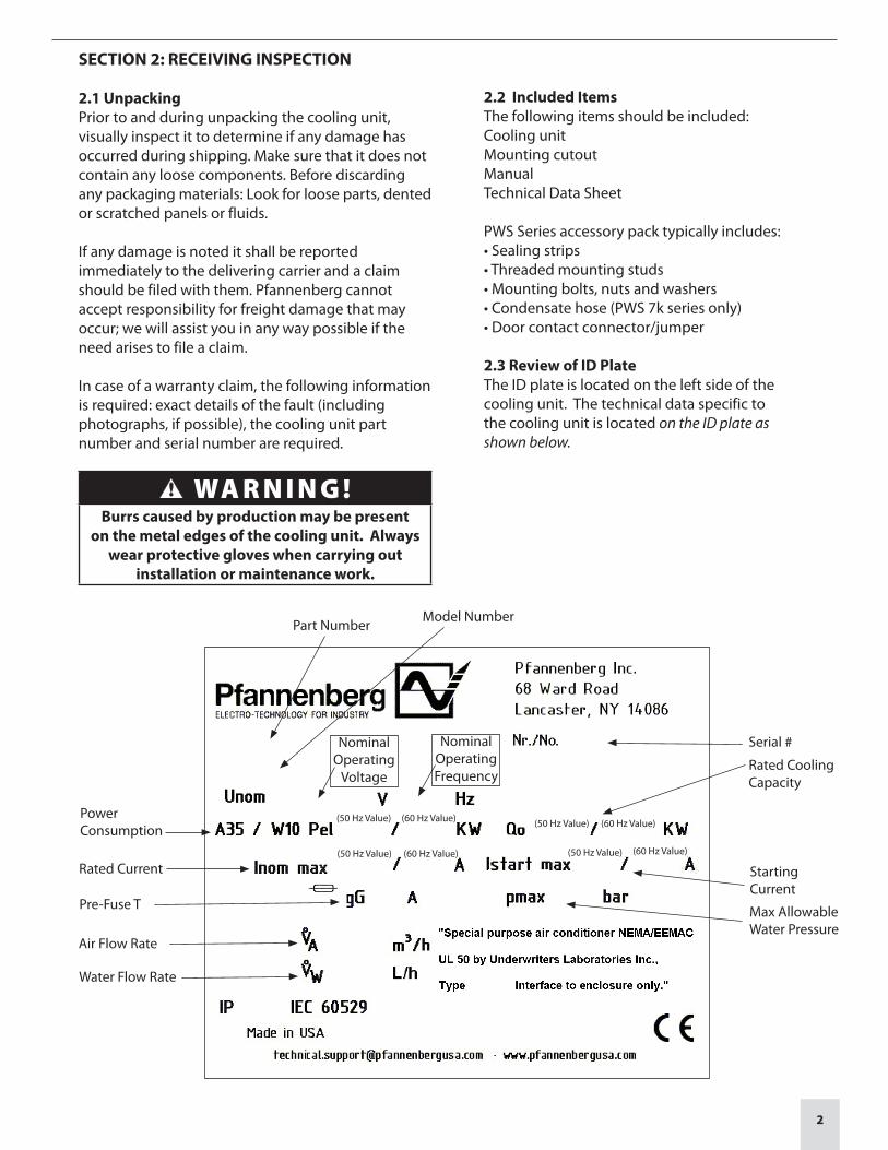
2.3 Review of ID PlateThe ID plate is located on the left side of the cooling unit. The technical data specific to the cooling unit is located on the ID plate as shown below.
PowerConsumption
Part Number
Serial #
StartingCurrent
Max AllowableWater Pressure
Rated CoolingCapacity
(50 Hz Value) (60 Hz Value)
Model Number
(50 Hz Value) (60 Hz Value)
(50 Hz Value) (60 Hz Value)
(50 Hz Value) (60 Hz Value)
Nominal Operating
Voltage
NominalOperatingFrequency
Rated Current
Pre-Fuse T
Air Flow Rate
Water Flow Rate
PWS Series Air/Water Heat Exchangers
3
SECTION 3: HANDLING
3.1 TransportingThe cooling unit shall only be moved in the fully assembled condition.
If the cooling unit is being shipped with an electrical panel enclosure it shall be packed separately from the electrical enclosure.
3.2 StorageThe cooling unit shall not be exposed to temperatures exceeding +70ºC.
If the device is stored or transported at temperatures below freezing, the water circuit must be completely emptied using compressed air.
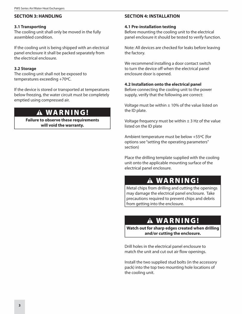
WA R N I N G !Failure to observe these requirements
will void the warranty.
SECTION 4: INSTALLATION
4.1 Pre-installation testingBefore mounting the cooling unit to the electrical panel enclosure it should be tested to verify function.
Note: All devices are checked for leaks before leaving the factory.
We recommend installing a door contact switch to turn the device off when the electrical panel enclosure door is opened.
4.2 Installation onto the electrical panelBefore connecting the cooling unit to the power supply, verify that the following are correct:
Voltage must be within ± 10% of the value listed on the ID plate.
Voltage frequency must be within ± 3 Hz of the value listed on the ID plate
Ambient temperature must be below +55ºC (for options see “setting the operating parameters” section)
Place the drilling template supplied with the cooling unit onto the applicable mounting surface of the electrical panel enclosure.
WA R N I N G !Metal chips from drilling and cutting the openings may damage the electrical panel enclosure. Take precautions required to prevent chips and debris from getting into the enclosure.
WA R N I N G !Watch out for sharp edges created when drilling
and/or cutting the enclosure.
Drill holes in the electrical panel enclosure to match the unit and cut out air flow openings.
Install the two supplied stud bolts (in the accessory pack) into the top two mounting hole locations of the cooling unit.
4
WA R N I N G !Please note the information on the “Thread Reach for Set Screw” label attached to the
cooling unit. If the noted installed thread depth is exceeded the cooling unit may be damaged.
Install the cooling unit mounting insulation strips (in the accessory pack) to the cooling unit as noted on the individual cooling unit information sheet.Make sure that the insulation strips are correctly attached and placed correctly on the cooling unit. The correct fitting and location of the insulation strips is required for the proper operation of the cooling unit.
Attach the cooling unit to the electrical panel enclosure by use of the stud bolts inserted as described above.
WA R N I N G !Do not move the cooling unit by the piping. Doing so will damage the cooling unit and
void the warranty.
The cooling unit is then completely attached to the electrical panel enclosure from inside the enclosure by use of the screws and washers supplied in the accessory pack.
Tighten the fasteners until the cooling unit insulation strips are compressed to a thickness of 2 mm (approximately .080”)
Install Drain hose barb (provided in accessory bag for PWS 3k series only) then attach the condensate drainage hose to the drain.
Reinstall the cover using the original mounting screws.
4.3 Power connection
WA R N I N G !
Make sure that the main power supply to the cooling unit is turned off while making the
power connections.
The cooling unit power supply shall be fused as indicated on the unit ID plate by means of a series connected power line connection.
All power connections and / or repairs, if or when required, shall only be carried out by authorized, trained electricians.
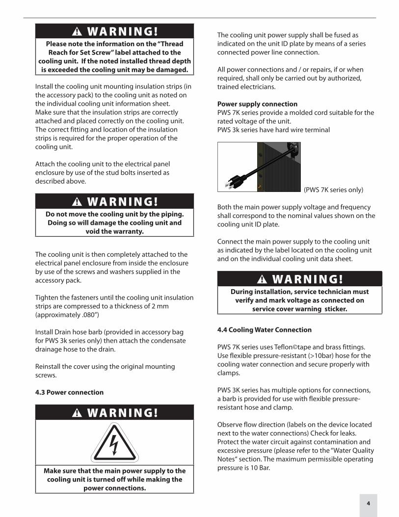
Power supply connectionPWS 7K series provide a molded cord suitable for the rated voltage of the unit.PWS 3k series have hard wire terminal
(PWS 7K series only)
Both the main power supply voltage and frequency shall correspond to the nominal values shown on the cooling unit ID plate.
Connect the main power supply to the cooling unit as indicated by the label located on the cooling unit and on the individual cooling unit data sheet.
WA R N I N G !During installation, service technician must
verify and mark voltage as connected on service cover warning sticker.
4.4 Cooling Water Connection
PWS 7K series uses Teflon©tape and brass fittings.Use flexible pressure-resistant (>10bar) hose for the cooling water connection and secure properly with clamps.
PWS 3K series has multiple options for connections, a barb is provided for use with flexible pressure-resistant hose and clamp.
Observe flow direction (labels on the device located next to the water connections) Check for leaks. Protect the water circuit against contamination and excessive pressure (please refer to the “Water Quality Notes“ section. The maximum permissible operating pressure is 10 Bar.
PWS Series Air/Water Heat Exchangers
5
SECTION 4: INSTALLATION CON'T
4.5 Condensation Water Connection
Drainage hose must be secured in place with clamps. To ensure reliable drainage of condensation water, please note the following:
The drain hose shall not be kinked. Hose cross-section must not be constricted in any way. The drainage hose must slope in the right direction.
To avoid excessive condensation water amounts, please note the following:
Adjust the cooling water temperature to the cooling performance required.
Only use the device on sealed electrical panels and housings.
Set the desired temperature only as low as is really necessary (to avoid the cooled air from dropping below the dewpoint).
4.6 Door Contact
To avoid an increased production of condensate and for safety reasons a door limit switch should be connected to the terminals provided.
WA R N I N G !No external voltage may be applied to the door contact
circuit or damage to the cooling unit may result.
In order to prevent any interference from outside signals, it is recommended that a shielded cable with a twisted pair leads be used for the connection. The cable shielding can be connected on one side to the PE (ground) connection point provided on the cooling unit.
If the use of a shielded cable is not possible, the cable that is used must not be routed in the immediate vicinity of potential sources of interference such as power supply lines , components with a relatively high electromagnetic emission (EMI), etc.
If no door contact switch is used, the connecting terminals must be jumpered for the cooling unit to operate.

6
SECTION 5: OPERATING CONDITIONS
5.1 RequirementsBefore connecting the cooling unit to the power supply, verify that the following are correct.Voltage must be within ± 10% of the value listed on the ID plate.
Voltage frequency must be within ± 3 Hz of the value listed on the ID plate
Ambient temperature must be below +55ºC (for options see Section 6.5)
Make sure that the airflow inside of the electrical panel enclosure is not restricted by internal components.
WA R N I N G !If the cooling unit is being mounted on the door of the electrical panel enclosure, it must be confirmed that the door hinges can support the additional weight of the cooling unit and that the electrical panel enclosure is securely fastened so that the panel enclosure will not topple over.
5.2 Theory of Operation
The cooling units are available in two options:
A.) With Water (solenoid) Valve and ThermostatB.) Without Water Valve and Thermostat
A.) With Water (solenoid) Valve and Thermostat
∞
1 Water Valve (solenoid)2 Heat Exchanger (condensor)3 Fan4 Thermostat with Temperature Sensor
The water valve (1) controls if water is allowed to flow through the cooling unit.
As the water flows through the heat exchanger (2) it absorbs the heat from air in the electrical panel enclosure while also dehumidifying it. This process lowers the temperature of the air in the electrical panel enclosure.
This is accomplished by the fan (3) pulling in the hot air from the electrical panel enclosure and pushing it through the heat exchanger (2) and back into the electrical panel enclosure at a lower temperature.
The cooling unit (with water valve and thermostat)is electronically controlled. To accomplish this a temperature sensor monitors the temperature inside the electrical panel enclosure and regulates the function of the water valve.
B.) Without Water Valve and Thermostat
∞
1 Water Inlet2 Heat Exchanger (condensor)3 Fan
The flow of water through the unit is regulated by a control system provided by the user outside of the coolling unit.
As the water flows through the heat exchanger (2) it absorbs the heat from air in the electrical panel enclosure while also dehumidifying it. This process lowers the temperature of the air in the electrical panel enclosure.
This is accomplished by the fan (3) pulling in the hot air from the electrical panel enclosure and pushing it through the heat exchanger (2) and back into the electrical panel enclosure at a lower temperature.
PWS Series Air/Water Heat Exchangers
7
SECTION 6: UNIT START-UP
6.1 GeneralThe cooling unit is equipped with an temperature control system. The temperature of the air pulled in from the electrical panel enclosure into the cooling unit is measured by a temperature sensor.
WA R N I N G !Ambient conditions and temperatures
in the electrical panel must be in accordance with the values indicated in the cooling unit
information sheet.
WA R N I N G !Unit must be operated with the cover installed.
Unit can not cool properly when cover is not in place.
6.2 Setting the Operating Parameters
6.2.1 Units with Water (Solenoid) Valve and Thermostat
The cooling unit fan runs continuously.
The solenoid valve controls cooling water flow according to the internal temperature setting in the switch cabinet.
The desired internal temperature of the switch cabinet is set using the thermostat. Factory setting is at 35°C / 95°F. Adjustment range min. 8°C / 46.4°F - max. 50°C / 122°F. Electrical panel enclosure internal temperature > the desired value set using the thermostat
Solenoid valve open Coolant flows.
Electrical panel enclosure internal temperature < the desired value set using the thermostat .
Solenoid valve shut coolant does not flow.
If door contact is opened then the unit cycles off.
Temperature Monitoring
If the internal temperature of the electrical panel enclosure deviates more than 10º C from the desired value set (factory setting 35°C / 95°F) using the
thermostat then the zero potential two-way switch is triggered.
This switch is wired to the terminal strip.
Wiring diagram (Technical sheet)(Wiring diagram on device)
6.2.2 Units without Water Valve and Thermostat
The cooling unit fan runs continuously.
The cooling water flow is controlled centralized water flow control supplied by the customer.
The door contact cycles the unit on / off. The door contact output notifies of an open door condition.
SECTION 7: MAINTENANCE
Pfannenberg air/water heat exchangers are maintenance-free.
Use of a water filter is essential if the cooling water is contaminated. Please refer to the “Water Quality Notes“ section.
Check the condensation water drainage equipment at regular intervals.
SECTION 8: TROUBLESHOOTING
Condensation water drainage out of the electrical panel enclosure must be ensured when the device is installed.
To prevent frost damage the temperature in the water circuit must not fall below the minimum permissible water temperature of +1°C anywhere in the system.
If the device is stored or transported at temperatures below freezing the water circuit must be completely emptied using compressed air.

8
SECTION 9: DESIGN DATA
Please refer to the cooling unit individual technical data sheets for the following:
Dimensional DataMounting CutoutCircuit Diagrams
9.1 Water Quality NotesThe following guidelines must be complied with to ensure safe and reliable operation of air/water heat exchangers.
Cooling water should not contain any sedimentation, should be of low hardness (low carbon hardness in particular), especially for re-cooling. However, it should not be so soft that it corrodes material/s used in the exchanger.
When recycling cooling water the saline content due to evaporation of larger quantities of water must not be too high (increasing concentrations of dissolved substances increase electrical conductivity, resulting in the water becoming more corrosive). Constantly remove some enriched water and replace it with an equal amount of fresh water.
Water containing gypsum is unsuitable for cooling, as it tends to cause scale deposits, which are very hard to remove.
Cooling water should be iron- and manganese-free (deposits leading to piping blockage may otherwise result). Organic substances (sludge and microbiological contaminants)should only be present in the water in very small amounts.
Common contamination forms and remedies Water Contamination Remedy
Mechanical contamination Filter water using -Sieve filters - Gravel filters - Cartridge filters -Pre-coated filters
Excessive hardness Soften water using ion exchange
Moderate mechanical contaminant and hardness promoting substance content Treat water using stabilisers or dispersants
Moderate chemical contaminant content Treat water using passivation media and / or inhibitors
Biological contamination - sludge bacteria, algae Treat water with biocides
PWS Series Air/Water Heat Exchangers
9
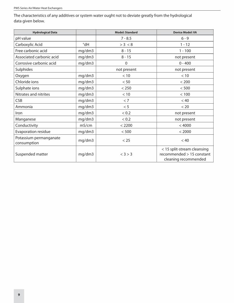
The characteristics of any additives or system water ought not to deviate greatly from the hydrological data given below.
Hydrological Data Model: Standard Device Model: VA
pH value 7 - 8.5 6 - 9Carboxylic Acid °dH > 3 < 8 1 - 12Free carbonic acid mg/dm3 8 - 15 1 - 100Associated carbonic acid mg/dm3 8 - 15 not presentCorrosive carbonic acid mg/dm3 0 0 - 400Sulphides not present not presentOxygen mg/dm3 < 10 < 10Chloride ions mg/dm3 < 50 < 200Sulphate ions mg/dm3 < 250 < 500Nitrates and nitrites mg/dm3 < 10 < 100CSB mg/dm3 < 7 < 40Ammonia mg/dm3 < 5 < 20Iron mg/dm3 < 0.2 not presentManganese mg/dm3 < 0.2 not presentConductivity mS/cm < 2200 < 4000Evaporation residue mg/dm3 < 500 < 2000Potassium permanganate consumption mg/dm3 < 25 < 40
Suspended matter mg/dm3 < 3 > 3< 15 split-stream cleansing
recommended > 15 constant cleaning recommended
10
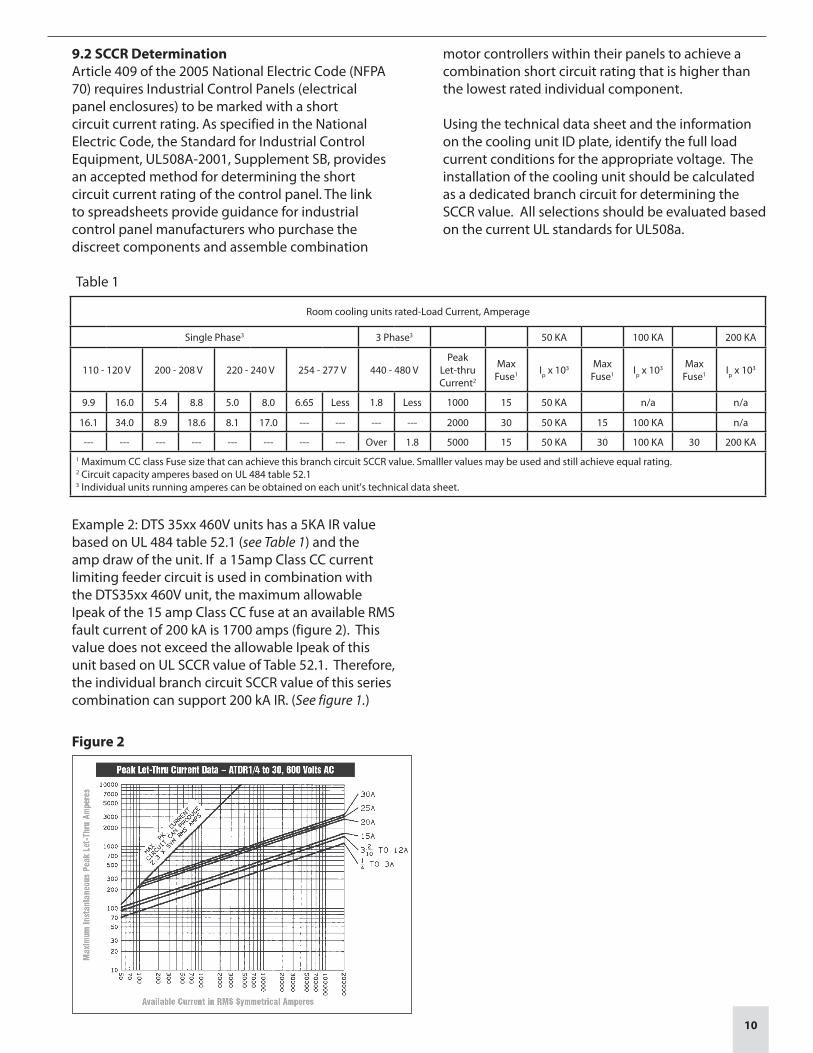
9.2 SCCR DeterminationArticle 409 of the 2005 National Electric Code (NFPA 70) requires Industrial Control Panels (electrical panel enclosures) to be marked with a short circuit current rating. As specified in the National Electric Code, the Standard for Industrial Control Equipment, UL508A-2001, Supplement SB, provides an accepted method for determining the short circuit current rating of the control panel. The link to spreadsheets provide guidance for industrial control panel manufacturers who purchase the discreet components and assemble combination
motor controllers within their panels to achieve a combination short circuit rating that is higher than the lowest rated individual component.
Using the technical data sheet and the information on the cooling unit ID plate, identify the full load current conditions for the appropriate voltage. The installation of the cooling unit should be calculated as a dedicated branch circuit for determining the SCCR value. All selections should be evaluated based on the current UL standards for UL508a.
Table 1
Room cooling units rated-Load Current, Amperage
Single Phase3 3 Phase3 50 KA 100 KA 200 KA
110 - 120 V 200 - 208 V 220 - 240 V 254 - 277 V 440 - 480 VPeak
Let-thru Current2
Max Fuse1 Ip x 103 Max
Fuse1 Ip x 103 Max Fuse1 Ip x 103
9.9 16.0 5.4 8.8 5.0 8.0 6.65 Less 1.8 Less 1000 15 50 KA n/a n/a
16.1 34.0 8.9 18.6 8.1 17.0 --- --- --- --- 2000 30 50 KA 15 100 KA n/a
--- --- --- --- --- --- --- --- Over 1.8 5000 15 50 KA 30 100 KA 30 200 KA1 Maximum CC class Fuse size that can achieve this branch circuit SCCR value. Smalller values may be used and still achieve equal rating.2 Circuit capacity amperes based on UL 484 table 52.13 Individual units running amperes can be obtained on each unit's technical data sheet.
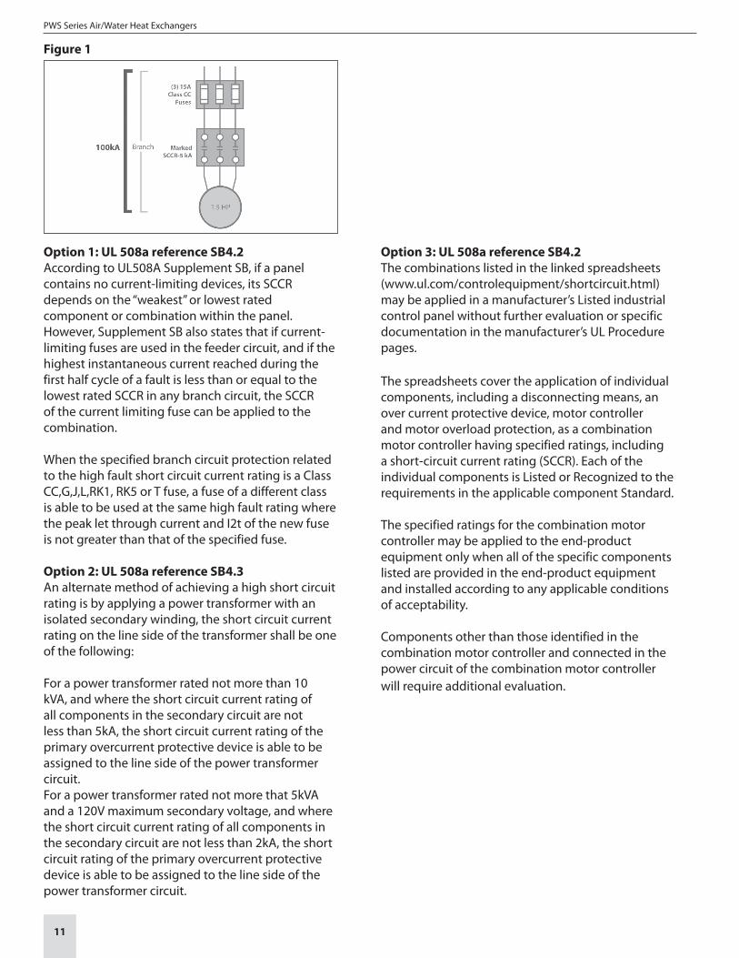
Example 2: DTS 35xx 460V units has a 5KA IR value based on UL 484 table 52.1 (see Table 1) and the amp draw of the unit. If a 15amp Class CC current limiting feeder circuit is used in combination with the DTS35xx 460V unit, the maximum allowable Ipeak of the 15 amp Class CC fuse at an available RMS fault current of 200 kA is 1700 amps (figure 2). This value does not exceed the allowable Ipeak of this unit based on UL SCCR value of Table 52.1. Therefore, the individual branch circuit SCCR value of this series combination can support 200 kA IR. (See figure 1.)
Figure 2
PWS Series Air/Water Heat Exchangers
11
Option 1: UL 508a reference SB4.2According to UL508A Supplement SB, if a panel contains no current-limiting devices, its SCCR depends on the “weakest” or lowest rated component or combination within the panel. However, Supplement SB also states that if current-limiting fuses are used in the feeder circuit, and if the highest instantaneous current reached during the first half cycle of a fault is less than or equal to the lowest rated SCCR in any branch circuit, the SCCR of the current limiting fuse can be applied to the combination.
When the specified branch circuit protection related to the high fault short circuit current rating is a Class CC,G,J,L,RK1, RK5 or T fuse, a fuse of a different class is able to be used at the same high fault rating where the peak let through current and I2t of the new fuse is not greater than that of the specified fuse.
Option 2: UL 508a reference SB4.3An alternate method of achieving a high short circuit rating is by applying a power transformer with an isolated secondary winding, the short circuit current rating on the line side of the transformer shall be one of the following:
For a power transformer rated not more than 10 kVA, and where the short circuit current rating of all components in the secondary circuit are not less than 5kA, the short circuit current rating of the primary overcurrent protective device is able to be assigned to the line side of the power transformer circuit.For a power transformer rated not more that 5kVA and a 120V maximum secondary voltage, and where the short circuit current rating of all components in the secondary circuit are not less than 2kA, the short circuit rating of the primary overcurrent protective device is able to be assigned to the line side of the power transformer circuit.
Option 3: UL 508a reference SB4.2The combinations listed in the linked spreadsheets (www.ul.com/controlequipment/shortcircuit.html)may be applied in a manufacturer’s Listed industrial control panel without further evaluation or specific documentation in the manufacturer’s UL Procedure pages.
The spreadsheets cover the application of individual components, including a disconnecting means, an over current protective device, motor controller and motor overload protection, as a combination motor controller having specified ratings, including a short-circuit current rating (SCCR). Each of the individual components is Listed or Recognized to the requirements in the applicable component Standard.
The specified ratings for the combination motor controller may be applied to the end-product equipment only when all of the specific components listed are provided in the end-product equipment and installed according to any applicable conditions of acceptability.
Components other than those identified in the combination motor controller and connected in the power circuit of the combination motor controller will require additional evaluation.
Figure 1
12
SECTION 10: WARRANTY INFORMATION
(WARRANTY IS VALID FOR 1 YEAR)
Warranty becomes null and void:In case of improper usage of the unit, noncompliance with operating conditions or nonobservance of instructions the warranty becomes null and void.
If operated in rooms in which corrosives or acids are present in the atmosphere.
In case of damage caused by contaminated or jammed air filters.
If a non-authorized person interrupts the cooling circulation, modifies the unit or changes the serial number.
In case of damage caused by transport or by accidents.
For the exchange of parts by non-authorized companies.
In order to maintain your warranty rights please observe the following when returning the unit.
Enclose an exact description of the fault in the shipping package.
Enclose proof of delivery (delivery note or copy of invoice).
Return the unit together with all accessories; use the original packaging or packaging of equivalent quality, send the unit freight prepaid and covered by an adequate transport insurance.
Pfannenberg Incorporated68 Ward Road, Lancaster, New York 14086Phone: 716-685-6866 Fax: 716-681-1521email: [email protected]
ELECTRO-TECHNOLOGY FOR INDUSTRY
Org 08/09© 2013 Pfannenberg Incorporated