pwrog-18068, 'use of direct fracture toughness for
TRANSCRIPT

Global Expertise • One Voice
PWROG-18068, “Use of Direct Fracture Toughness for Evaluation of RPV Integrity” Pre-submittal Meeting, October 14, 2020
Westinghouse Non-Proprietary
© 2020 Westinghouse Electric Company LLC
All Rights Reserved

Safety Minute• COVID-19
• Good hygiene• Healthy Lifestyle• Clean work equipment• Practice social distancing
• Tripping Hazards• Chair legs• Small Areas• Electrical cords on the floor
• Other Safety Issues• Drinks in the vicinity of computers and power strips

Agenda• Introductions• Objective of the meeting• Background• Content of PWROG-18068• Summary• Open discussion
PWROG-18068, "Use of Direct Fracture Toughness for Evaluation of RPV Integrity"

Objective of Meeting• Present an overview of PWROG-18068,
“Use of Direct Fracture Toughness for Evaluation of RPV Integrity” prior to submittal
PWROG-18068, "Use of Direct Fracture Toughness for Evaluation of RPV Integrity"
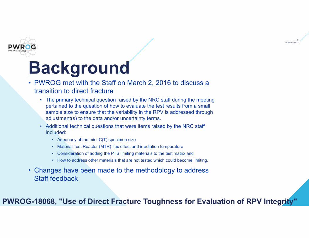
Background• PWROG met with the Staff on March 2, 2016 to discuss a
transition to direct fracture• The primary technical question raised by the NRC staff during the meeting
pertained to the question of how to evaluate the test results from a small sample size to ensure that the variability in the RPV is addressed through adjustment(s) to the data and/or uncertainty terms.
• Additional technical questions that were items raised by the NRC staff included:
• Adequacy of the mini-C(T) specimen size• Material Test Reactor (MTR) flux effect and irradiation temperature • Consideration of adding the PTS limiting materials to the test matrix and • How to address other materials that are not tested which could become limiting.
• Changes have been made to the methodology to address Staff feedback
PWROG-18068, "Use of Direct Fracture Toughness for Evaluation of RPV Integrity"

EXECUTIVE SUMMARY ............................................................................................................. xii
1 PURPOSE ..................................................................................................................... 1-12 BACKGROUND ............................................................................................................. 2-1
2.1 CURRENT APPROACH..................................................................................... 2-12.2 ADVANTAGES TO EVALUATIONS BASED ON DIRECT FRACTURE
TOUGHNESS .................................................................................................... 2-42.3 RECOMMENDATION FOR REACTOR PRESSURE VESSEL INTEGRITY ..... 2-72.4 U.S. NRC APPROVAL AND PRECEDENT OF MASTER CURVE TECHNOLOGY
........................................................................................................................... 2-72.4.1 Zion Nuclear Power Station................................................................. 2-72.4.2 Kewaunee Nuclear Station .................................................................. 2-82.4.3 Linde 80 Weld Metals .......................................................................... 2-82.4.4 Lessons-Learned from the Beaver Valley Master Curve License
Amendment Request .......................................................................... 2-92.5 INTERNATIONAL ACCEPTANCE OF MASTER CURVE TECHNOLOGY ........ 2-9
2.5.1 Europe ................................................................................................. 2-92.5.2 Japan .................................................................................................. 2-9
2.6 RISK-INFORMED METHODS ......................................................................... 2-102.7 CONCLUSION ................................................................................................. 2-10
3 U.S. NUCLEAR REGULATORY COMMISSION REGULATIONS ................................. 3-13.1 10 CFR 50.61 ..................................................................................................... 3-13.2 10 CFR 50, APPENDIX G .................................................................................. 3-2
3.2.1 NRC Approved Methods for Developing P-T Curves .......................... 3-33.3 10 CFR 50, APPENDIX H .................................................................................. 3-4
4 METHODOLOGY FOR APPLICATION OF MASTER CURVE TEST DATA .................. 4-14.1 GENERATION AND VALIDATION OF IRRADIATED DATA ............................... 4-14.2 IRRADIATED SPECIMEN TESTING ................................................................. 4-24.3 IRRADIATED DATA ADJUSTMENTS ................................................................ 4-3
4.3.1 Chemistry (Cu, Mn, Ni and P) ............................................................. 4-44.3.2 Temperature ........................................................................................ 4-54.3.3 Fluence ............................................................................................... 4-54.3.4 Flux ..................................................................................................... 4-54.3.5 Correlation between ΔT30 and ΔT0 ...................................................... 4-7
4.4 MARGIN TERM ................................................................................................. 4-94.4.1 Determination of σtest ........................................................................... 4-94.4.2 Determination of σadditional ..................................................................... 4-94.4.3 Determination of σtempspecimen and σtempRPV .......................................... 4-104.4.4 Determination of σfluencespecimen and σfluenceRPV ..................................... 4-10
4.5 UNCERTAINTY DUE TO MATERIAL VARIABILITY ......................................... 4-115 OVERALL SUMMARY ................................................................................................... 5-16 REFERENCES .............................................................................................................. 6-1
Table of Contents
PWROG-18068, "Use of Direct
Fracture Toughness for
Evaluation of RPV Integrity“
J. Brian HallWestinghouse

Purpose• This topical report discusses a methodology that justifies the use of
irradiated fracture toughness data to demonstrate that reactor pressure vessel (RPV) integrity as an alternative to meet the requirements of pressurized thermal shock (PTS) (10 CFR 50.61) and pressure-temperature (P-T) limit curves (10 CFR 50, Appendix G). Specifically, this topical report discusses a methodology to:
• Generate irradiated master curve reference temperature (T0) data• Adjust the data for differences between the tested material and the RPV
component of interest• Account for test result uncertainty and material variability in the respective RPV
component and• Apply the data using a robust bases and the ASME Section XI Code
PWROG-18068, "Use of Direct Fracture Toughness for Evaluation of RPV Integrity"

Background• Current Approach: RTNDT + shift + margin
– RTNDT is not a good transition temperature fracture metric: • Margin for any given material unknown and inconsistent
– Shift has substantial margin (σΔ) and prediction uncertainty– Baseline RV material transition temperature (RTNDT) is based on a very
conservative method from 1972• RTNDT is composed of drop-weight nil-ductility transition temperature
(TNDT) and Charpy tests• TNDT is a measure of crack arrest transition temperature
• We no longer use the KIR (crack arrest) curve for P-T curves• We now use the KIC (crack initiation) curve• Initiation fracture toughness transition temperature (T0) and RTNDT
are not correlated
PWROG-18068, "Use of Direct Fracture Toughness for Evaluation of RPV Integrity"
ASME PVP2014‐28540, 2014

Background –Direct Fracture Toughness• Master Curve
– Reduced uncertainty– Reduced inconsistency– Characterizes margin statistically– Based on actual fracture toughness measurement
PWROG-18068, "Use of Direct Fracture Toughness for Evaluation of RPV Integrity"
WRC Bulletin 457
WRC Bulletin 457
WRC Bulletin 457
NUREG-1807
Recommendation for RPV Integrity• It is recommended that there would be a valid ASTM E1921 T0
master curve reference temperature for limiting and potentially limiting beltline materials irradiated to a fluence greater than or near to that material’s peak fluence at the end of the license period (40, 60 or 80 years).
• Furthermore, the licensees would have the ability to routinely use irradiated T0 data with a well-defined methodology and uncertainty term(s) for pressurized thermal shock (PTS, 10 CFR 50.61) and pressure-temperature (P-T) limit curve (10 CFR 50, Appendix G) evaluations.
PWROG-18068, "Use of Direct Fracture Toughness for Evaluation of RPV Integrity"

NRC Approval and Precedent of Master Curve Technology• Successfully used for following RPVs
• Zion - 1994• Kewaunee - 2001• B&W High Cu Linde 80 Welds – 2005
• ASME Boiler and Pressure Vessel (B&PV) Section XI Code, (RG 1.147, incorporated in 10 CFR 50.55a)
• RTT0 as an alternative to RTNDT was incorporated into • Code Case N-629, 2003 (replaced by N-851)• ASME Section XI, Appendix G, Subarticle G-2110, 2013
• Code Case N-830, 2020 (T0 with master curve 5% lower bound)
PWROG-18068, "Use of Direct Fracture Toughness for Evaluation of RPV Integrity"

RPV Integrity Regulations• 10CFR50.61
• RTPTS must be calculated in accordance with RTNDT = RTNDT(U) + M + ΔRTNDT and RTNDT as defined in the ASME Code, Paragraph NB–2331, although other methods approved by the Director, Office of Nuclear Reactor Regulation are also allowed
• An exemption is required to use RTT0 (unirradiated or irradiated)• 10 CFR 50, Appendix G
• …methods of analysis and the margins of safety of XI, Appendix G • RTT0 as an alternative to RTNDT was incorporated into
• ASME Section XI, Appendix G, Subarticle G-2110, 2013• Code Case N-830, 2020 (T0 with master curve 5% lower bound)• “…subject to the approval of the regulatory authority having jurisdiction at the plant
site.”• PWROG-18068 provides an alternative methodology to comply with the above
regulationsPWROG-18068, "Use of Direct Fracture Toughness for Evaluation of RPV Integrity"

NRC Approved Methodologies for Developing P-T Curves• Both WCAP-14040-A, Revision 4 and BAW-10046A, Revision 2 specify
• Determination of RTNDT in accordance with ASME III, NB-2300 and• ART in accordance with RG 1.99 R2
• Therefore, PWROG-18068 provides an alternative methodology to specific sections only
• WCAP-14040-A, Revision 4 sections 2.3 and 2.4• BAW-10046A, Revision 2 section 3
PWROG-18068, "Use of Direct Fracture Toughness for Evaluation of RPV Integrity"
PWROG-18068, "Use of Direct Fracture Toughness for Evaluation of RPV Integrity"
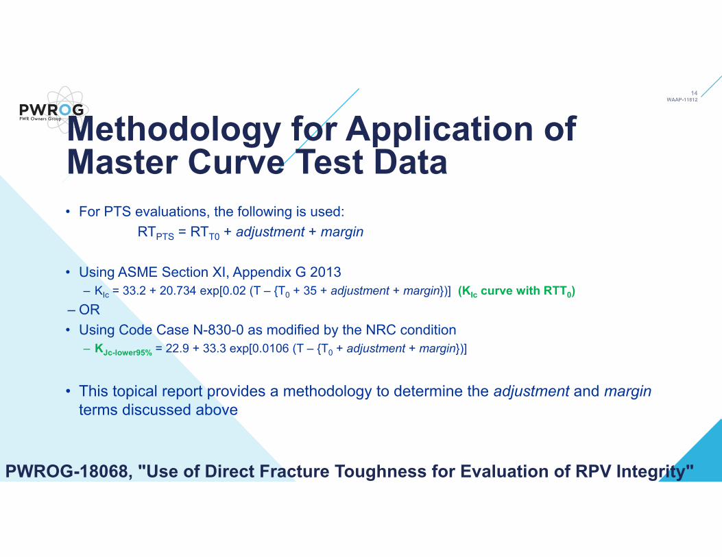
• For PTS evaluations, the following is used:RTPTS = RTT0 + adjustment + margin
• Using ASME Section XI, Appendix G 2013 – KIc = 33.2 + 20.734 exp[0.02 (T – {T0 + 35 + adjustment + margin})] (KIc curve with RTT0)
– OR• Using Code Case N-830-0 as modified by the NRC condition
– KJc-lower95% = 22.9 + 33.3 exp[0.0106 (T – {T0 + adjustment + margin})]
• This topical report provides a methodology to determine the adjustment and marginterms discussed above
Methodology for Application of Master Curve Test Data

• Irradiated T0 can be obtained by• Using existing data• Testing specimens machined from material irradiated in a PWR surveillance
capsule, or• Irradiating specimens in a material test reactor (MTR)
• MTR irradiation must include validation material in each Cu group that have test materials
• Low Cu: Cu weight percent (wt. %) ≤ 0.072• Medium Cu: Cu wt. % between 0.072 and High Cu value• High Cu: Cu wt. % > 0.243 for Linde 80 welds or > 0.301 for all other materials
• Ensures that MTR irradiated specimens are representative of PWR irradiated specimens• Potential Flux effect• Other differences: spectrum, temperature, unknown• Ensures a well-designed MTR irradiation of specimens
PWROG-18068, "Use of Direct Fracture Toughness for Evaluation of RPV Integrity"
Generation and Validation of Irradiated Data

• Irradiation of the same heat of material is required to evaluate the RPV material of interest
• Testing in accordance with ASTM E1921-19• Data sets are screened for inhomogeneity in accordance with 10.6 of ASTM
E1921-19• Data sets that fail the screening criterion are evaluated in accordance with
Appendix X5 “Treatment of Potentially Inhomogeneous Data Sets,” of ASTM E1921-19 with T0IN (as calculated in Appendix X5) substituted for T0.
• Any geometry that meets ASTM E1921-19• Mini-CT validation presented in Appendix A• An 18°F bias is added for the 3-point bend Charpy size specimen (ASTM E1921-
19)
PWROG-18068, "Use of Direct Fracture Toughness for Evaluation of RPV Integrity"
Irradiated Specimen Testing
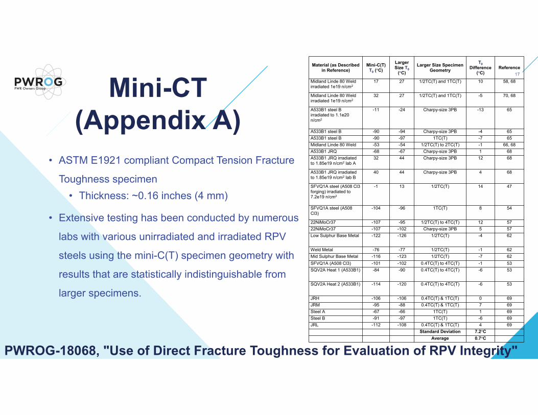
Mini-CT (Appendix A)
• ASTM E1921 compliant Compact Tension Fracture
Toughness specimen• Thickness: ~0.16 inches (4 mm)
• Extensive testing has been conducted by numerous
labs with various unirradiated and irradiated RPV
steels using the mini-C(T) specimen geometry with
results that are statistically indistinguishable from
larger specimens.
Material (as Described in Reference)
Mini-C(T) T0 (°C)
Larger Size T0
(°C)Larger Size Specimen
GeometryT0
Difference (°C)
Reference
Midland Linde 80 Weld irradiated 1e19 n/cm2
17 27 1/2TC(T) and 1TC(T) 10 58, 68
Midland Linde 80 Weld irradiated 1e19 n/cm2
32 27 1/2TC(T) and 1TC(T) -5 70, 68
A533B1 steel B irradiated to 1.1e20 n/cm2
-11 -24 Charpy-size 3PB -13 65
A533B1 steel B -90 -94 Charpy-size 3PB -4 65A533B1 steel B -90 -97 1TC(T) -7 65Midland Linde 80 Weld -53 -54 1/2TC(T) to 2TC(T) -1 66, 68A533B1 JRQ -68 -67 Charpy-size 3PB 1 68A533B1 JRQ irradiated to 1.85e19 n/cm2 lab A
32 44 Charpy-size 3PB 12 68
A533B1 JRQ irradiated to 1.85e19 n/cm2 lab B
40 44 Charpy-size 3PB 4 68
SFVQ1A steel (A508 Cl3 forging) irradiated to 7.2e19 n/cm2
-1 13 1/2TC(T) 14 47
SFVQ1A steel (A508 Cl3)
-104 -96 1TC(T) 8 54
22NiMoCr37 -107 -95 1/2TC(T) to 4TC(T) 12 5722NiMoCr37 -107 -102 Charpy-size 3PB 5 57Low Sulphur Base Metal -122 -126 1/2TC(T) -4 62
Weld Metal -76 -77 1/2TC(T) -1 62Mid Sulphur Base Metal -116 -123 1/2TC(T) -7 62SFVQ1A (A508 Cl3) -101 -102 0.4TC(T) to 4TC(T) -1 53SQV2A Heat 1 (A533B1) -84 -90 0.4TC(T) to 4TC(T) -6 53
SQV2A Heat 2 (A533B1) -114 -120 0.4TC(T) to 4TC(T) -6 53
JRH -106 -106 0.4TC(T) & 1TC(T) 0 69JRM -95 -88 0.4TC(T) & 1TC(T) 7 69Steel A -67 -66 1TC(T) 1 69Steel B -91 -97 1TC(T) -6 69JRL -112 -108 0.4TC(T) & 1TC(T) 4 69
Standard Deviation 7.2°CAverage 0.7°C
PWROG-18068, "Use of Direct Fracture Toughness for Evaluation of RPV Integrity"

• Tested irradiated specimens will rarely reflect the exact same irradiation conditions and chemistry as the represented RPV material
• Adjustments presented herein are made using the embrittlement trend curve (ETC) codified in 10CFR50.61a
• PWROG-18068 will use ASTM E900-15 ETC• However an exemption will be required from 10CFR50.61 for PTS
• adjustment = (predicted ΔT30 of the RPV material at the fluence of interest –predicted ΔT30 of the irradiated tested material) * average shift difference between ΔT30 and ΔT0
• Best-estimate inputs are used for the irradiated data adjustments (Cu, Ni, Mn, P, Temp., Fluence, EFPY)
• An NRC-approved method of fluence evaluation consistent with the plant licensing basis, or another NRC-approved method of fluence evaluation
PWROG-18068, "Use of Direct Fracture Toughness for Evaluation of RPV Integrity"
Irradiated Data Adjustment
ORNL/TM‐2012/567

• Accounts for uncertainties • T0 determination• ETC (if the irradiated data adjustment is large)• Irradiation temperature
• Test specimens• RPV
• Fluence• Test specimens• RPV
PWROG-18068, "Use of Direct Fracture Toughness for Evaluation of RPV Integrity"
Margin Term

• σtest is calculated in accordance with paragraph
10.10 of ASTM E1921 • (with standard calibration practices, σexp = 4°C)
• Uncertainty due to material variability• In 2019, a homogeneity screening procedure was
added to ASTM E1921-19, Appendix X5• Identifies datasets which do not follow expected normal material
Weibull distribution and the 95% lower bound curve would not bound 95% of data
• Inhomogeneity can result from initial toughness variation (i.e. segregation) or uneven embrittlement due to chemistry variation
• T0max is based on the worst fracture toughness test data point and does not have to include any margin
PWROG-18068, "Use of Direct Fracture Toughness for Evaluation of RPV Integrity"
Determination of σtest
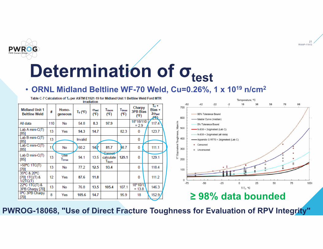
• ORNL Midland Beltline WF-70 Weld, Cu=0.26%, 1 x 10¹⁹ n/cm2
PWROG-18068, "Use of Direct Fracture Toughness for Evaluation of RPV Integrity"≥ 98% data bounded
Determination of σtest

• If the adjustment is > 2·σETC, σadditional is required
• If the adjustment is < 2·σETC, then the error on the adjustment is negligible
and does not need to be considered. Thus, σadditional = 0 in this case
PWROG-18068, "Use of Direct Fracture Toughness for Evaluation of RPV Integrity"
Determination of σadditionalσadditional = σETC· ∆
PWROG-18068, "Use of Direct Fracture Toughness for Evaluation of RPV Integrity"
Determination of σtempspecimen and σtempRPV• Irradiation Temperature
• σtempspecimen = the effect of uncertainty of the specimen irradiation temperature on embrittlement using the ETC at the specimen best estimate condition
• σtempRPV = the effect of the uncertainty of the RPV irradiation temperature on embrittlement using the ETC at the RPV best estimate condition
• The uncertainty of the Tcold time-weighted average for RPV and RVSP capsules is small since it is measured often and averaged over many cycles
• (2°F can conservatively be used) • For MTR irradiations, the temperature uncertainty is provided by the irradiation
facility• If the specimens were irradiated in a surveillance capsule contained in the
assessed RPV, the capsule irradiation temperature uncertainty is addressed in the RPV irradiation temperature uncertainty term and σtempspecimen =0
• σfluencespecimen = the effect of uncertainty of the specimen fluence on embrittlement using the ETC at the specimen best estimate condition
• σfluenceRPV = the effect of uncertainty of the RPV fluence on embrittlement using the ETC at the RPV best estimate condition
• Use of a least-squares evaluation considering in-capsule dosimetry measurements is used for the specimens.
• If ex-vessel dosimetry measurements are available, use of a least-squares evaluation considering dosimetry measurements is used for the RPV.
PWROG-18068, "Use of Direct Fracture Toughness for Evaluation of RPV Integrity"
Determination of σfluencespecimen and σfluenceRPV
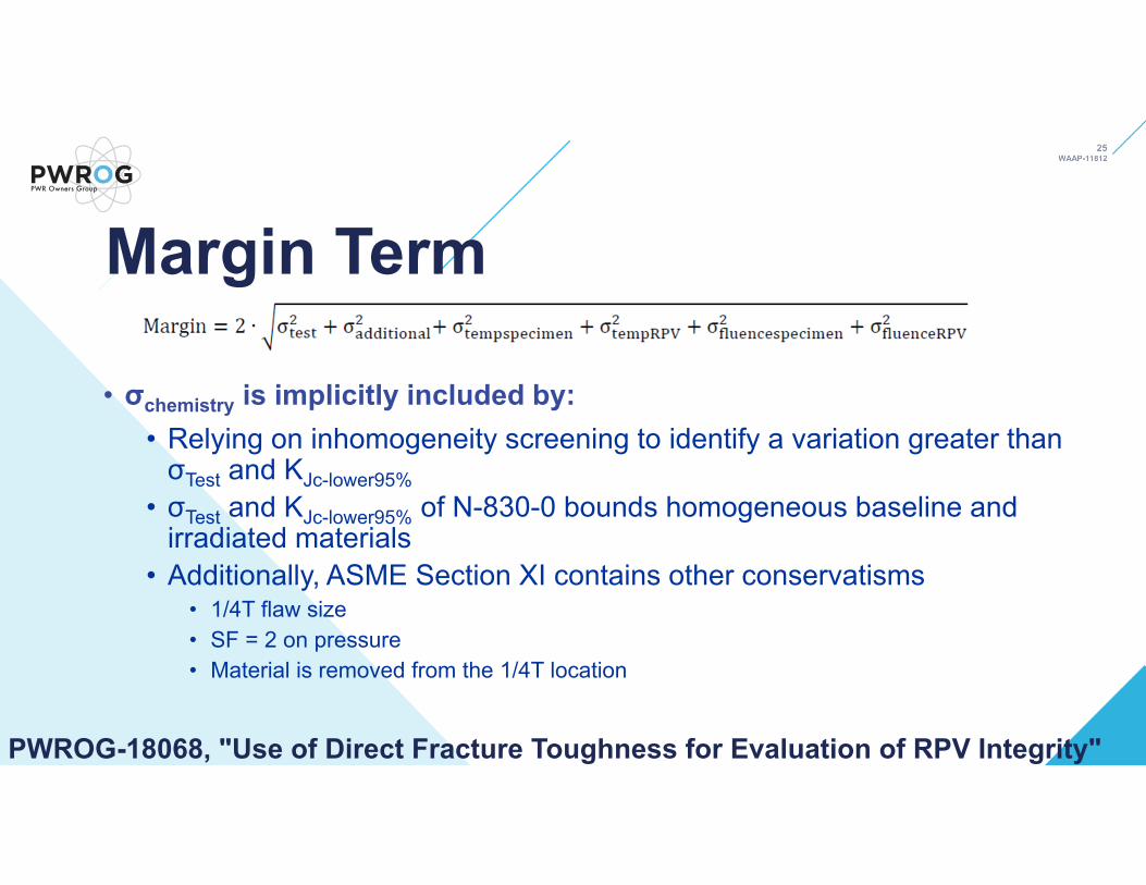
• σchemistry is implicitly included by:• Relying on inhomogeneity screening to identify a variation greater than σTest and KJc-lower95%
• σTest and KJc-lower95% of N-830-0 bounds homogeneous baseline and irradiated materials
• Additionally, ASME Section XI contains other conservatisms• 1/4T flaw size• SF = 2 on pressure• Material is removed from the 1/4T location
PWROG-18068, "Use of Direct Fracture Toughness for Evaluation of RPV Integrity"
Margin Term

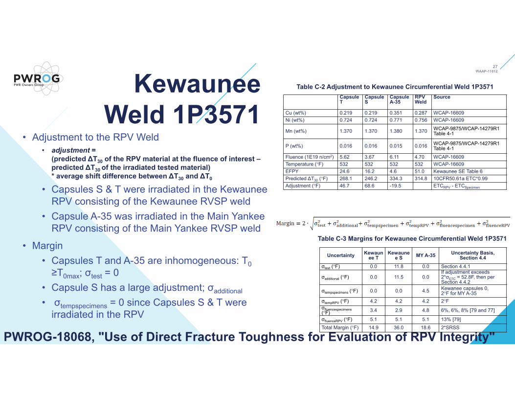
Example Kewaunee Weld 1P3571
(Appendix C.1)• In 2001 the NRC approved a master
curve LAR for Kewaunee weld 1P3571• The heat was irradiated in 3 capsules and
tested for T0
• It is a good comparison test
• WCAP-16609 noted scatter in the test results
• Consistent with inhomogeneous screening results
• 2 of 3 datasets were screened as inhomogeneous
PWROG-18068, "Use of Direct Fracture Toughness for Evaluation of RPV Integrity"
Capsule T Capsule S Capsule A-35
Toughness Data Source WCAP-16641-NPTable C-1
WCAP-16609-NPTable A-2
WCAP-16609-NPTable A-3
Number of Tests 12 12 8T0 (ºF) 160.6 145.5 225.3Valid per ASTM E1921-19 paragraph 10.5 Yes Yes Yes
T0scrn per ASTM E1921-19 paragraph 10.6 (ºF) 211.3 150.8 257.7
Screening Criterion ASTM E1921-19 paragraph 10.6.3 (ºF) 14.0 13.5 17.6
Homogeneous No Yes NoT0IN Calculation ASTM E1921-19 paragraph X5 X5.2.2 Not applicable X5.2.1
T0IN (ºF) X5.2.2 211.3 Not applicable 257.7T0max (ºF) X5.2.1 202.0 Not applicable 255.6Charpy 3PB Bias (ºF) 18 18 18T0IN or T0 + Bias (ºF) 229.3 163.5 273.6
Table C-1 Calculation of T0 per ASTM E1921-19 and Homogeneity Screen
Kewaunee Weld 1P3571
• Adjustment to the RPV Weld• adjustment =
(predicted ΔT30 of the RPV material at the fluence of interest –predicted ΔT30 of the irradiated tested material) * average shift difference between ΔT30 and ΔT0
• Capsules S & T were irradiated in the Kewaunee RPV consisting of the Kewaunee RVSP weld
• Capsule A-35 was irradiated in the Main Yankee RPV consisting of the Main Yankee RVSP weld
• Margin• Capsules T and A-35 are inhomogeneous: T0≥T0max; σtest = 0
• Capsule S has a large adjustment; σadditional
• σtempspecimens = 0 since Capsules S & T were irradiated in the RPV
PWROG-18068, "Use of Direct Fracture Toughness for Evaluation of RPV Integrity"
Table C-2 Adjustment to Kewaunee Circumferential Weld 1P3571CapsuleT
CapsuleS
CapsuleA-35
RPVWeld
Source
Cu (wt%) 0.219 0.219 0.351 0.287 WCAP-16609Ni (wt%) 0.724 0.724 0.771 0.756 WCAP-16609
Mn (wt%) 1.370 1.370 1.380 1.370 WCAP-9875/WCAP-14279R1Table 4-1
P (wt%) 0.016 0.016 0.015 0.016 WCAP-9875/WCAP-14279R1Table 4-1
Fluence (1E19 n/cm2) 5.62 3.67 6.11 4.70 WCAP-16609Temperature (°F) 532 532 532 532 WCAP-16609EFPY 24.6 16.2 4.6 51.0 Kewaunee SE Table 6Predicted ΔT30 (°F) 268.1 246.2 334.3 314.8 10CFR50.61a ETC*0.99Adjustment (°F) 46.7 68.6 -19.5 ETCRPV - ETCSpecimen
Uncertainty Kewaunee T
Kewaunee S MY A-35 Uncertainty Basis,
Section 4.4σtest (°F) 0.0 11.8 0.0 Section 4.4.1
σadditional (°F) 0.0 11.5 0.0If adjustment exceeds 2*σETC = 52.8F, then per Section 4.4.2
σtempspecimens (°F) 0.0 0.0 4.5 Kewanee capsules 0, 2°F for MY A-35
σtempRPV (°F) 4.2 4.2 4.2 2°Fσfluencespecimens(°F) 3.4 2.9 4.8 6%, 6%, 8% [79 and 77]
σfluenceRPV (°F) 5.1 5.1 5.1 13% [79]Total Margin (°F) 14.9 36.0 18.6 2*SRSS
Table C-3 Margins for Kewaunee Circumferential Weld 1P3571

Kewaunee Weld 1P3571
• The 2001 NRC Kewaunee approved master curve methodology yielded a PTS = 291°F
• 10CFR 50.61 PTS = 307°F• PWROG-18068 PTS = 312°F
• Many differences in the methodologies• RG1.99 R2 vs. 10CFR50.61a ETC adjustments• Monte Carlo uncertainty margin vs. E1921
homogeneity screening• The Kewaunee example produces results that are
greater than the old 2001 NRC approved methodology for Kewaunee and greater than 10CFR50.61 PTS value
PWROG-18068, "Use of Direct Fracture Toughness for Evaluation of RPV Integrity"

• Heat 72105 was irradiated in• The Ford MTR, Zion 1 surveillance capsules,
B&W MIRVSP capsules• The capsules contained various material
sources: Midland 1 RPV beltline, Midland 1 Nozzle course weld, Midland 1 Nozzle drop-outs, and the Zion 1 RVSP weld
• All fall into the high Cu group, so a comparison can be used to validate the Ford MTR irradiation
• Nozzle Course Weld:• 30 tests were divided into 2 subsets to
demonstrate methodology with typical sample sizes
• All subsets are homogeneous
PWROG-18068, "Use of Direct Fracture Toughness for Evaluation of RPV Integrity"
Example Linde 80 Weld Heat 72105 (Appendix C.2)
ORNL Ford
Reactor All Data
ORNL Ford Reactor
Subset with Test Temps. 65 & 75ºC
ORNL Ford Reactor
Subset with Test Temps. 25 & 45ºC
B&W CR3-LG2
Capsule
Toughness Data Source Table 15 [67] Table 15 [67] Table 15 [67] Table D-4
[31]Number of Tests 30 12 16 10T0 (ºF) 132.0 146.6 123.3 67.6
Valid per ASTM E1921-19 paragraph 10.5 Yes Yes Yes Yes
T0scrn per ASTM E1921-19 paragraph 10.6 (ºF) 137.7 146.6 123.3 69.8
Screening Criterion ASTM E1921-19 paragraph 10.6.3 (ºF)
8.8 13.5 12.2 15.5
Homogeneous Yes Yes Yes YesT0IN Calculation ASTM E1921-19 paragraph X5
Not applicable Not applicable Not
applicableNot
applicable
T0IN (ºF) Not applicable Not applicable Not
applicableNot
applicable
T0max (ºF) Not applicable Not applicable Not
applicableNot
applicable
σtest per Section 4.4 (ºF) 9.5 11.8 11.1 12.9
Charpy 3PB Bias (ºF) 18*9/28 = 5.8 0 18*9/16 =
10.118*6/10 =
10.8T0IN or T0 + Bias (ºF) 137.8 146.6 133.4 78.4
Table C-5 Calculation of T0 per ASTM E1921-19 for Midland Nozzle Course Weld
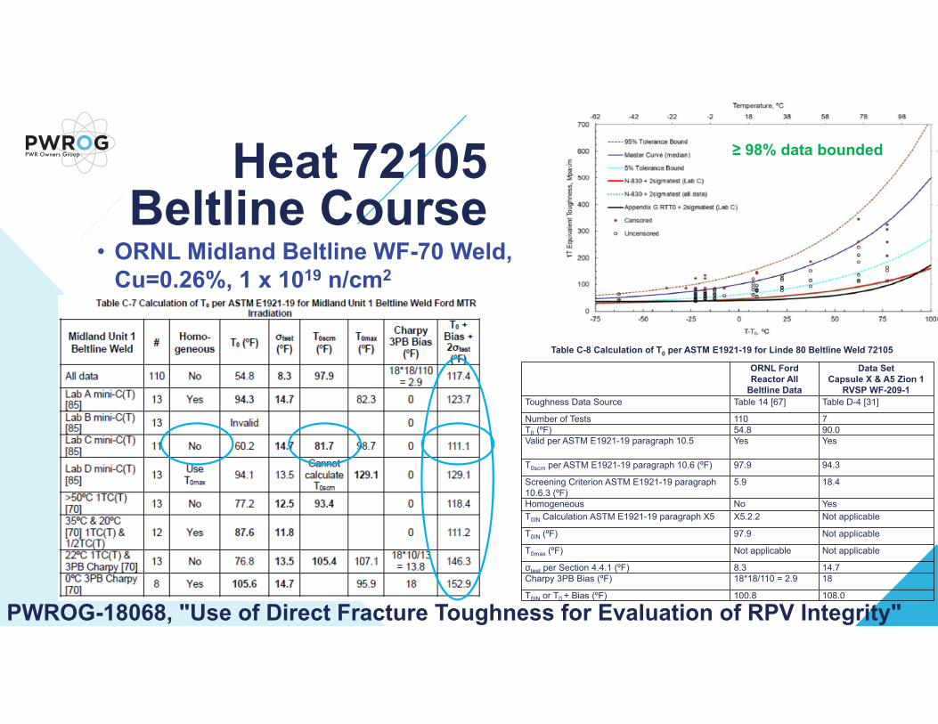
• ORNL Midland Beltline WF-70 Weld, Cu=0.26%, 1 x 10¹⁹ n/cm2
PWROG-18068, "Use of Direct Fracture Toughness for Evaluation of RPV Integrity"
Heat 72105 Beltline Course
ORNL Ford Reactor All
Beltline Data
Data SetCapsule X & A5 Zion 1
RVSP WF-209-1Toughness Data Source Table 14 [67] Table D-4 [31]
Number of Tests 110 7T0 (ºF) 54.8 90.0Valid per ASTM E1921-19 paragraph 10.5 Yes Yes
T0scrn per ASTM E1921-19 paragraph 10.6 (ºF) 97.9 94.3
Screening Criterion ASTM E1921-19 paragraph 10.6.3 (ºF)
5.9 18.4
Homogeneous No YesT0IN Calculation ASTM E1921-19 paragraph X5 X5.2.2 Not applicable
T0IN (ºF) 97.9 Not applicable
T0max (ºF) Not applicable Not applicable
σtest per Section 4.4.1 (ºF) 8.3 14.7Charpy 3PB Bias (ºF) 18*18/110 = 2.9 18
T0IN or T0 + Bias (ºF) 100.8 108.0
Table C-8 Calculation of T0 per ASTM E1921-19 for Linde 80 Beltline Weld 72105
≥ 98% data bounded
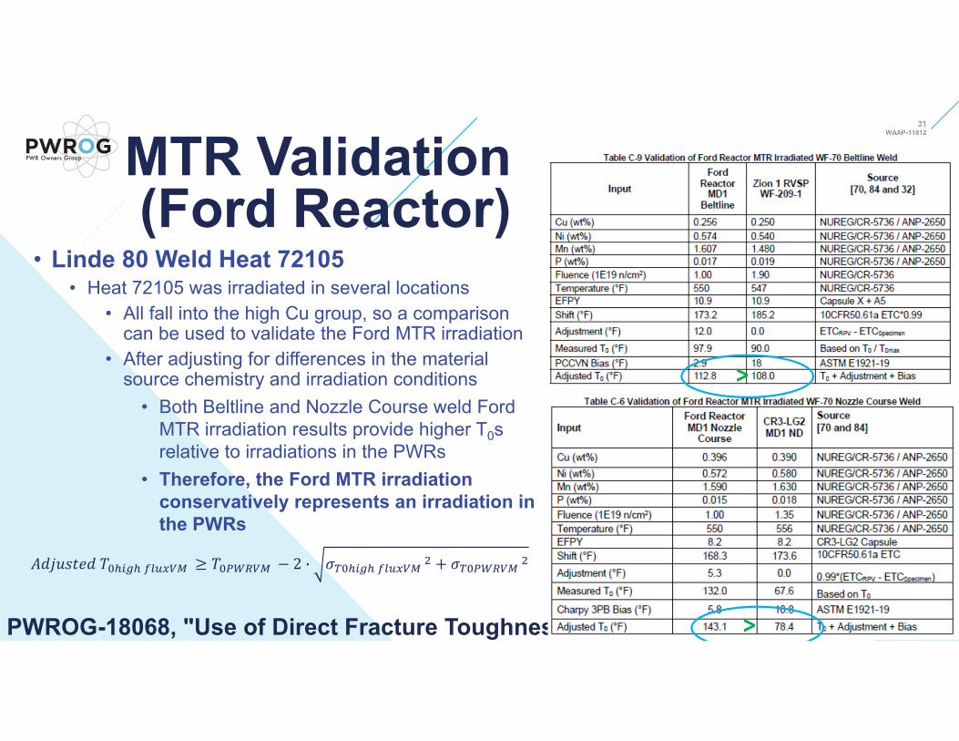
• Linde 80 Weld Heat 72105• Heat 72105 was irradiated in several locations
• All fall into the high Cu group, so a comparison can be used to validate the Ford MTR irradiation
• After adjusting for differences in the material source chemistry and irradiation conditions
• Both Beltline and Nozzle Course weld Ford MTR irradiation results provide higher T0s relative to irradiations in the PWRs
• Therefore, the Ford MTR irradiation conservatively represents an irradiation in the PWRs
PWROG-18068, "Use of Direct Fracture Toughness for Evaluation of RPV Integrity"
>
>
2 ·
MTR Validation (Ford Reactor)
• Adjust for all differences to the RPV location of interest using ETC
PWROG-18068, "Use of Direct Fracture Toughness for Evaluation of RPV Integrity"
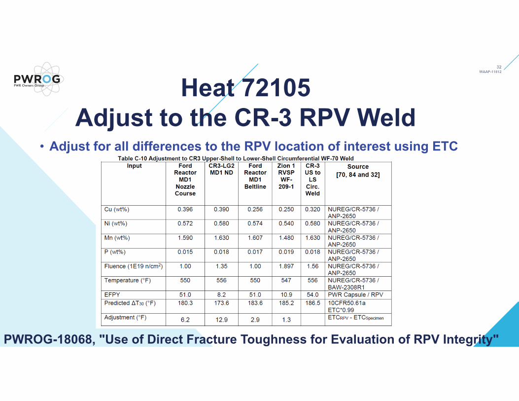
Heat 72105 Adjust to the CR-3 RPV Weld
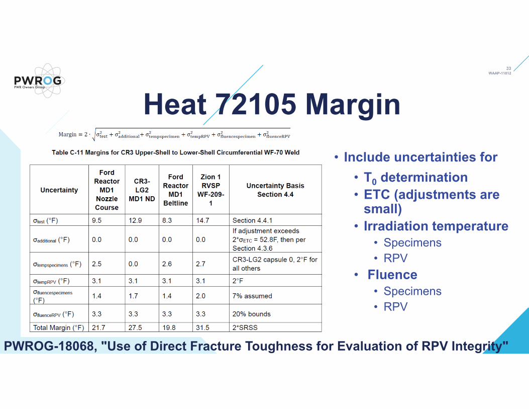
• Include uncertainties for• T0 determination• ETC (adjustments are
small)• Irradiation temperature
• Specimens• RPV
• Fluence• Specimens• RPV
PWROG-18068, "Use of Direct Fracture Toughness for Evaluation of RPV Integrity"
Heat 72105 Margin
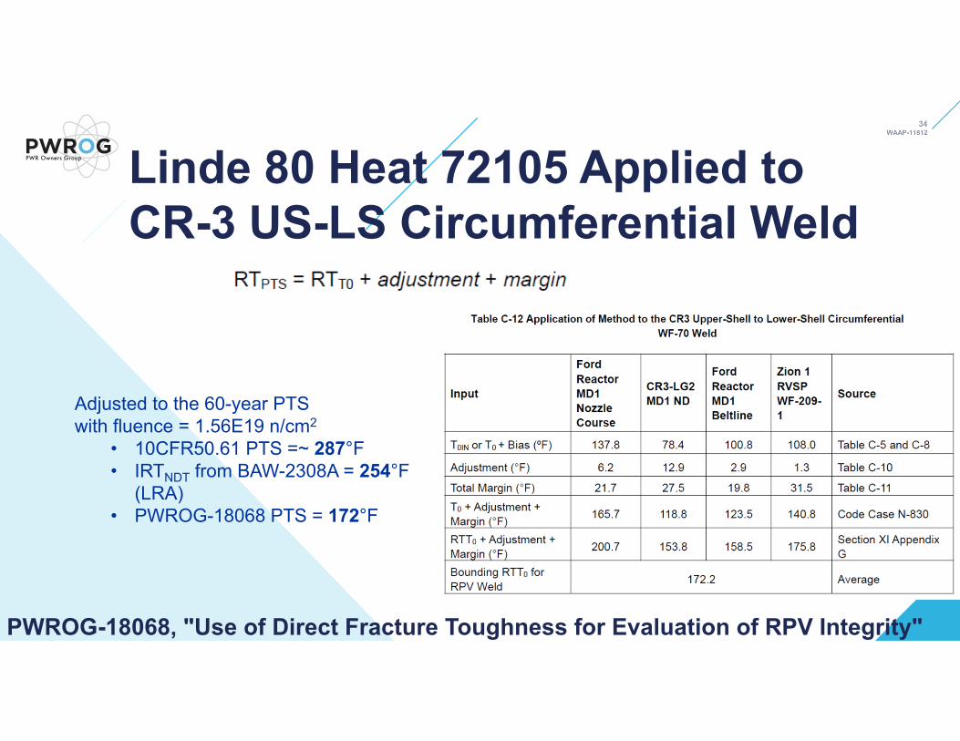
Linde 80 Heat 72105 Applied to CR-3 US-LS Circumferential Weld
Adjusted to the 60-year PTS with fluence = 1.56E19 n/cm2
• 10CFR50.61 PTS =~ 287°F• IRTNDT from BAW-2308A = 254°F
(LRA)• PWROG-18068 PTS = 172°F
PWROG-18068, "Use of Direct Fracture Toughness for Evaluation of RPV Integrity"

PWROG-18068 SummaryThe benefits of an irradiated direct fracture toughness data evaluation methodology are:
• Establishes a robust fracture toughness basis for license renewal terms, which will ensure public safety by enabling a statistical understanding of the actual safety margin that exists
• Provides an overall cost savings to both NRC and licensees for managing RPV integrity.
PWROG-18068, "Use of Direct Fracture Toughness for Evaluation of RPV Integrity"

PWROG-18068 Summary• This topical report discusses a methodology that justifies the use of irradiated fracture
toughness data to demonstrate that reactor pressure vessel (RPV) integrity as an alternative for meeting the requirements of pressurized thermal shock (PTS) (10 CFR 50.61) and pressure-temperature (P-T) limit curves (10 CFR 50, Appendix G).
• Specifically, this topical report discusses a methodology to: • Generate irradiated master curve reference temperature (T0) data• Adjust the data for differences between the tested material and the RPV component
of interest• Account for test result uncertainty and material variability in the respective RPV
component and• Apply the data using a robust bases and the ASME Section XI Code
PWROG-18068, "Use of Direct Fracture Toughness for Evaluation of RPV Integrity"

Open Discussion
PWROG-18068, "Use of Direct Fracture Toughness for Evaluation of RPV Integrity"