pv system permitting and inspection pv codes and … · pv system permitting and inspection...
TRANSCRIPT

Inspecting PV Systems for Code-Compliance 1
PV System Permitting and Inspection
PV System Permitting and Inspection
Presented by
Bill Brooks, PE
Brooks Engineering
Presented by
Bill Brooks, PE
Brooks Engineering
PV Codes and Standards 101
What are the applicable codes and standards for PV systems?
• Electrical codes - NEC Article 690 - Solar Photovoltaic Systems – NFPA 70
• Building Codes – ICC, ASCE 7• 2009 Uniform Solar Energy Code—IAPMO • UL Standard 1703, Flat-plate Photovoltaic
Modules and Panels• IEEE 1547, Standard for Interconnecting
Distributed Resources with Electric Power Systems
• UL Standard 1741, Standard for Inverters, Converters, Controllers and Interconnection System Equipment for Use With Distributed Energy Resources
2009 Uniform Solar Energy Code• Covers solar thermal systems and partially covers
photovoltaic systems
• Provisions for installation of single wall heat
exchangers
• Requires access to solar collector and its
components for maintenance and repair purposes
• Provides protection requirements for freezing
temperatures, water hammer, rodents, corrosion,
ultraviolet radiation, decay and termites

Inspecting PV Systems for Code-Compliance 2
2009 Uniform Solar Energy Code—Cont.• Waterproofing requirements when solar
collector is installed on a building structure to
prevent leakage
• The Uniform Plumbing Code© (UPC) sections in
this code are taken from the 2009 edition of
the Uniform Plumbing Code.
• The Uniform Mechanical Code© (UMC) sections
in this code are taken from the 2009 edition of
the Uniform Mechanical Code.
Photovoltaic System Basics

Inspecting PV Systems for Code-Compliance 3
Current varies with irradiance
Siemens Solar Module SP75Performance at Different Irradiances
0
1
2
3
4
5
6
0 5 10 15 20 25
Voltage (volts)
Cur
rent
(am
ps)
1000 W/m2, 25 oC800 W/m2, 25 oC600 W/m2, 25 oC400 W/m2, 25 oC200 W/m2, 25 oC
Voltage varies with temperature
Siemens Solar Module SP75Performance at Different Cell Temperatures
0
1
2
3
4
5
6
0 5 10 15 20 25
Voltage (volts)
Cur
rent
(am
ps)
1000 W/m2, 0 oC1000 W/m2, 25 oC1000 W/m2, 45 oC1000 W/m2, 60 oC
Differences Between PV and Conventional Electrical Systems
• PV systems have dc circuits that require special design and equipment.
• PV systems can have multiple energy sources, and special disconnects are required to isolate components.
• Energy flows in PV systems may be bi-directional.
• Utility-Interactive PV systems require an interface with the ac utility-grid and special considerations must be adopted. (utility must be involved-hence utility training)
Ain’t that purdy….

Inspecting PV Systems for Code-Compliance 4
…and this is so much prettier…
NEC Article 690 overview
PV Systems and the NEC
• Article 690 addresses safety standards for the installation of PV systems.
• Many other articles of the NEC may also apply to most PV installations.
NEC Sections Applicable to PV Systems
• Article 110: Requirements for Electrical Installations
• Chapter 2: Wiring and Protection− Most of the chapter--especially− Article 250: Grounding
• Chapter 3: Wiring Methods and Materials− Most of the chapter—especially− Article 300: Wiring Methods− Article 310: Conductors for General Wiring
• Article 480: Storage Batteries• Article 690: Solar Photovoltaic Systems

Inspecting PV Systems for Code-Compliance 5
NEC Article 690:Solar Photovoltaic Systems• I. General (definitions, installation)• II. Circuit Requirements (sizing, protection)• III. Disconnect Means (switches, breakers)• IV. Wiring methods (connectors)• V. Grounding (array, equipment)• VI. Markings (ratings, polarity, identification)• VII. Connection to Other Sources• VIII. Storage batteries• IX. Systems over 600 Volts
NEC Article 690:Solar Photovoltaic Systems• I. General (definitions, installation)
− 690.1 Scope—PV Systems (only)− 690.2 Definitions—PV Output Circuit, Inverter Input
Circuit—1 ½ pages of PV-specific jargon− 690.3—“Wherever the requirements of other articles
of this Code and Article 690 differ, the requirements of Article 690 shall apply”
− 690.4—Installation “Equipment: …shall be identified and listed for the application”
− 690.5—Ground-Fault Protection—to reduce fire hazards
− 690.6—AC Module—dc wiring is considered internal
Electrical Equipment Listing
• AHJs generally require listing for components and electrical hardware.
• Some components available for PV systems may not have applicable or any listing.
• Recognized testing laboratories include:• UL• ETL Semko (Intertek)• CSA• TÜV
NEC Article 690:Solar Photovoltaic Systems• II. Circuit Requirements (sizing, protection)
− 690.7 Maximum Voltage—Table 690.7 and manufacturers data. Max. 600Vdc for residential.
− 690.8 Circuit Sizing and Current• 690.8(A) Max current = rated Isc x 1.25 = Imax• 690.8(B) Min ampacity and overcurrent = Imax x 1.25
− 690.9 Overcurrent Protection• 690.9(A) Generally required on all source circuits—
exception: a.)no backfeed; and, b.) total Imax less than conductor ampacity.
− 690.10 Stand-Alone Systems• Inverter output need only meet demand.• No multi-wire circuits on 120V inverters.

Inspecting PV Systems for Code-Compliance 6
NEC Article 690:Solar Photovoltaic Systems• III. Disconnect Means (switches, breakers)
− 690.13—Need to disconnect all conductors connected to building. No disconnect in grounded conductor
− 690.14—Location—details and options (more to come)
− 690.17—Switch or Circuit Breaker—Warning sign when line and load energized in open position.
NEC Article 690:Solar Photovoltaic Systems• IV. Wiring methods
− 690.31(A) FPN—PV modules get HOT− 690.31—single conductors outside conduit allowed
in array.− Table 690.31—temp. correction must be applied to
conductors.− 690.33—requirements for connectors.− 690.35—Ungrounded PV Power Systems
NEC Article 690:Solar Photovoltaic Systems• V. Grounding (system, equipment)
− 690.41 System Grounding• Over 50Vdc must be grounded or comply with 690.35
− 690.42 Point of System Grounding Connection—one point, at GFP device if provided.
− 690.43 Equipment Grounding—metal likely to become energized must be grounded—listed equipment can be used to bond modules to support structure..
− 690.45 Size of EGC—Table 250.122 with GFP− 690.47 Size of GEC—ac use Table 250.66; dc use
Table 250.166
Electrical System Grounding• The NEC defines grounding as a connection to
the earth with sufficiently low impedance and
having sufficient current-carrying capacity to
prevent the buildup of voltages.
• Grounding of electrical systems offers
personnel safety and minimizes the effects of
lightning and surges on equipment.

Inspecting PV Systems for Code-Compliance 7
Electrical Grounding Types(Huge Confusion Over These Terms)
• System Ground (grounding): Connecting the
circuit to ground (i.e. the negative of a dc array,
the neutral of a split single-phase system, or the
neutral of a bi-polar dc system)
• Equipment Ground (bonding): Connecting all non-
current carrying metal parts to ground (metal
enclosure, module frame, etc…)
Nice Lugs! (poor fasteners)
690.43 Equipment Grounding [2008 NEC]
• “Devices listed and identified for grounding the metallic frames of PV modules shall be permitted to bond the exposed metallic frames of PV modules to grounded mounting structures. Devices identified and listed for bonding the metallic frames of PV modules shall be permitted to bond the exposed metallic frames of PV modules to the metallic frames of adjacent PV modules.”
Early Improvements for Grounding

Inspecting PV Systems for Code-Compliance 8
NEC Article 690:Solar Photovoltaic Systems• VI. Markings (ratings, polarity, identification)
− 690.53—DC PV Power Source—4 items; rated current, rated voltage, max voltage, max current
− 690.54—Interactive System Point of Interconnection—rated ac current and voltage
− 690.56—Sign at service entrance when PV disconnect not located at the service disconnect.
NEC Article 690:Solar Photovoltaic Systems• VII. Connection to Other Sources
− 690.60 Listed inverters for grid-connected systems− 690.61 inverter deenergize when utility is out (part of
listing process)− 690.64 Point of Connection
• 690.64(A) Supply Side—230.82• 690.64(B) Load Side—dedicated breaker; 120% of busbar
or conductor; 2008 NEC requires sign and breaker location to obtain 120% allowance for all PV systems.
• VIII. Storage Batteries• IX. Systems over 600 Volts

Inspecting PV Systems for Code-Compliance 9
Summary of Key PV-Related Changes for the 2005 and
2008 National Electrical Code
II. Circuit Requirements [2008 NEC]
690.7 Maximum Voltage.• New table and calculation option.
• Table 690.7 is now graduated in 4ºC increments.
• “When open-circuit voltage temperature
coefficients are supplied in the instructions for
listed PV modules, they shall be used to
calculate the maximum photovoltaic system
voltage as required by 110.3(B) instead of using
Table 690.7.”
II. Circuit Requirements [2008 NEC]
690.7 Maximum Voltage.• Example Calculation• Shell SQ-175PC has a Voc Temperature Coefficient
in their literature of:− αVoc = -129 mV/ºC; Voc =44.6V− Coldest expected Temp=-25ºC; Rating @ 25ºC (STC)
• Vmax (per module) = 44.6V + [-129 mV/ºC x (1V/1000mV) x (-25ºC–25ºC)] = 51.05 Volts.
• Table 690.7 [2008]: Vmax = 44.6V x 1.20 = 53.52V• Table 690.7 [2005]: Vmax = 44.6V x 1.25 = 55.75V
III. Disconnecting Means [2005 NEC]
Article 690.14 (Additional Provisions)• Clarification on location of PV Disconnecting Means and
Location of Inverters in Not-Readily-Accessible Locations
• New Section (D) Utility-Interactive Inverters Mounted in Not-Readily Accessible Locations. Utility-interactive inverters shall be permitted to be mounted on roofs or other exterior areas that are not readily accessible. These installations shall comply with (1) through (4):− (1) A direct-current photovoltaic disconnecting means shall be
mounted within sight of or in the inverter.− (2) An alternating-current disconnecting means shall be
mounted within sight of or in the inverter.− (3) The alternating-current output conductors from the inverter
and an additional alternating-current disconnecting means for the inverter shall comply with 690.14(C)(1).
− (4) A plaque shall be installed in accordance with 705.10.

Inspecting PV Systems for Code-Compliance 10
Article 690.31 [2005 NEC]Wiring Methods Permitted
• New 690.31(E) related to PV Output Circuits in metallic raceways.
• “(E) Direct-Current Photovoltaic Source and Output Circuits Inside a Building. Where direct current photovoltaic source or output circuits of a utility-interactive inverter from a building-integrated or other photovoltaic system are run inside a building or structure, they shall be contained in metallic raceways or metal enclosures from the point of penetration of the surface of the building or structure to the first readily accessible disconnecting means. The disconnecting means shall comply with 690.14(A) through 690.14(D).”
Article 690.31 [2008 NEC] Wiring Methods Permitted
• New language in 690.31(B)
• “(B) Single-Conductor Cable. Single-conductor cable type USE-2, and single-conductor cable listed and labeled as photovoltaic (PV) wire shall be permitted in exposed outdoor locations in photovoltaic source circuits for photovoltaic module interconnections within the photovoltaic array. Exception: Raceways shall be used when required by 690.31(A).”
Side Note on Temperature310.10 FPN No. 2 [2005 NEC]
• New Fine Print Note (below)
− “FPN No. 2: Conductors installed in conduit exposed to direct sunlight in close proximity to rooftops have been shown, under certain conditions, to experience a temperature rise of 17°C (30°F) above ambient temperature on which the ampacity is based.”
Side Note on Temperature310.15(B)(2)[2008 NEC]
• Table 310.15(B)(2)(c) Ambient Temperature Adjustment for Conduits Exposed to Sunlight On or Above Rooftops Temperature AdderDistance Above Roof to Bottom of Conduit °C °F
0 – 13 mm (1⁄2 in.) 33 60
Above 13 mm (1⁄2 in.) – 90 mm (31⁄2 in.) 22 40
Above 90 mm (31⁄2 in.) – 300 mm (12 in.) 17 30
Above 300 mm (12 in.) – 900 mm (36 in.) 14 25

Inspecting PV Systems for Code-Compliance 11
Article 690.33 [2008 NEC] Connectors
• New language in 690.33(F)
• “(E) Interruption of Circuit. Connectors shall
be either (1) or (2):
• (1) Be rated for interrupting current without
hazard to the operator.
• (2) Be a type that requires the use of a tool to
open and marked “Do Not Disconnect Under
Load” or “Not for Current Interrupting.” ”
Article 690.35 Ungrounded Photovoltaic Power Systems
• Ungrounded systems have not been prohibited,
but the 2005 NEC was the first code cycle
where the requirements are specifically called
out.
• Included is an exception in 690.41 for
consistency.
Article 690.35 Ungrounded Photovoltaic Power Systems [2005, 2008]
• “Photovoltaic power systems shall be permitted to operate with ungrounded photovoltaic source and output circuits where the system complies with 690.35(A) through 690.35(G).− (A) Disconnects. All photovoltaic source and output circuit
conductors shall have disconnects complying with 690, Part III.− (B) Overcurrent Protection. All photovoltaic source and output
circuit conductors shall have overcurrent protectioncomplying with 690.9.
− (C) Ground-Fault Protection. All photovoltaic source and output circuits shall be provided with a ground-fault protection device or system that complies with (1) through (3):
• (1) Detects a ground fault.• (2) Indicates that a ground fault has occurred• (3) Automatically disconnects all conductors or causes the inverter
or charge controller connected to the faulted circuit to automatically cease supplying power to output circuits.
Article 690.35 Ungrounded Photovoltaic Power Systems (cont.)− (D) The photovoltaic source and output conductors shall consist of the following:− (1) Nonmetallic jacketed multiconductor cables− (2) Conductors installed in raceways, or− (3) Conductors listed and identified as Photovoltaic (PV) Wire installed as
exposed, single conductors.− (E) The photovoltaic power system direct-current circuits shall be permitted to
be used with ungrounded battery systems complying with 690.71(G).− (F) The photovoltaic power source shall be labeled with the following warning at
each junction box, combiner box, disconnect, and device where the ungrounded circuits may be exposed during service:
WARNINGELECTRIC SHOCK HAZARD
THE DC CIRCUIT CONDUCTORS OF THISPHOTOVOLTAIC POWER SYSTEM ARE
UNGROUNDED AND MAY BE ENERGIZEDWITH RESPECT TO GROUND DUE TO
LEAKAGE PATHS AND/OR GROUND FAULTS.− (G) The inverters or charge controllers used in systems with ungrounded
photovoltaic source and output circuits shall be listed for the purpose.

Inspecting PV Systems for Code-Compliance 12
Grounding—Numerous Changes in 2005 & 2008
• 690.42 Point of System Grounding Connection
• 690.43,.45,.46 Equipment Grounding
• Grounding Electrode Systems 690.47—Changed in
2005 and completely rewritten in 2008.
• 690.48 Continuity of Equipment Grounding Systems
• 690.49 Continuity of Photovoltaic Source and
Output Circuit Grounded Conductors
690.45 Size of Equipment Grounding Conductors [2008 NEC]
• “(A) General. Equipment grounding conductors in photovoltaic source and photovoltaic output circuits shall be sized in accordance with Table 250.122. Where no overcurrent protective device is used in the circuit, an assumed overcurrent device rated at the photovoltaic rated shortcircuit current shall be used in Table 250.122. Increases in equipment grounding conductor size to address voltage drop considerations shall not be required. The equipment grounding conductors shall be no smaller than 14 AWG.”
690.47(C) Systems with Alternating-Current and Direct-Current Grounding Requirements [2005 NEC]
• “Photovoltaic power systems with both alternating-current and direct-current (dc) grounding requirements shall be permitted to be grounded as described in (1) or (2):− (1) A grounding-electrode conductor shall be connected between
the identified dc grounding point to a separate dc grounding electrode. The dc grounding-electrode conductor shall be sized according to 250.166. The dc grounding electrode shall be bonded to the ac grounding electrode to make a grounding electrode system according to 250.52 and 250.53. The bonding conductor shall be no smaller than the largest grounding electrode conductor, either ac or dc.
− (2) The dc grounding electrode conductor and ac grounding electrode conductor shall be connected to a single grounding electrode. The separate grounding electrode conductors shall be sized as required by 250.66 (ac) and 250.166 (dc).”
690.47(C) Systems with Alternating-Current and Direct-Current Grounding Requirements [2008 NEC]
• 2008 NEC has 8 qualifying provisions to “assist” in specifying the grounding requirements.
• Attempt is to reduce the required size of grounding electrode conductor for utility-interactive inverters with GFP.
• The requirements are difficult to follow and do not encourage straightforward enforcement of provisions.
• See 2011 NEC to see the intent of 2008 NEC clarified.
Inspecting PV Systems for Code-Compliance 13
690.47(D) Additional Electrodes for Array Grounding [2008 NEC]
• “Grounding electrodes shall be installed in accordance with 250.52 at the location of all ground-and pole-mounted photovoltaic arrays and as close as practicable to the location of roof-mounted photovoltaic arrays. The electrodes shall be connected directly to the array frame(s) or structure.”− GEC from array frames to electrode sized to 250.166− No substitute for equipment grounding conductor− Ground-mount structure meeting 250.52 complies− Roof-mounted may use building steel meeting 250.52(A)(2)
• Exception 1—Arrays with integral loads (area lights)• Exception 2—If closer than 6’ from existing electrode
690.53 Marking: DC PV Power Source[2008 NEC]
• (1) Rated maximum power-point current− Imp x number of series strings
• (2) Rated maximum power-point voltage− Vmp x number of modules in series
• (3) Maximum system voltage− FPN to (3): See 690.7(A) for maximum photovoltaic
system voltage.• (4) Short-circuit current
− FPN to (4): See 690.8(A) for calculation of maximum circuit current.
• (5) Maximum rated output current of the charge controller (if installed)
Article 690.64 (B)(5) [2005 NEC]
• Clarification on not requiring individual clamping of circuit breakers for 690.60 (utility-interactive) inverters. Many inspectors will require clamps because they are not familiar with PV systems.
• “Circuit breakers, if backfed, shall be identified for such operation. Dedicated circuit breakers backfed from listed utility-interactive inverters complying with 690.60 shall not be required to be individually clamped to the panelboard bus bars. A front panel shall clamp all circuit breakers to the panelboard bus bars. Main circuit breakers connected directly to energized feeders shall also be individually clamped.”
2008 NEC Complete Rewrites Article 690.64 Point of Connection (B) Load Side
• “Where distribution equipment, including switchboards and panelboards, is fed simultaneously by a primary source(s) of electricity and one or more utility-interactive inverters, and where this distribution equipment is capable of supplying multiple branch circuits or feeders, or both, the interconnecting provisions for the utility-interactive inverter(s) shall comply with (B)(1) through (B)(7).”

Inspecting PV Systems for Code-Compliance 14
Article 690.64(B) (cont.)• “(1) Dedicated Overcurrent and Disconnect.
Each source interconnection shall be made at a dedicated circuit breaker or fusible disconnecting means.
• (2) Bus or Conductor Rating. The sum of the ampere ratings of overcurrent devices in circuits supplying power to a busbar or conductor shall not exceed 120 percent of the rating of the busbar or conductor. In systems with panelboards connected in series, the rating of the first overcurrent device directly connected to the output of a utility-interactive inverter(s) shall be used in the calculations for all busbars and conductors.”
Article 690.64(B) (cont.)• “(3) Ground-Fault Protection. The
interconnection point shall be on the line side of all ground-fault protection equipment.Exception: Connection shall be permitted to be made to the load side of ground-fault protection, provided that there is ground-fault protection for equipment from all ground-fault current sources. Ground-fault protection devices used with supplies connected to the load-side terminals shall be identified and listed as suitable for backfeeding.
• (4) Marking. Equipment containing overcurrent devices in circuits supplying power to a busbar or conductor supplied from multiple sources shall be marked to indicate the presence of all sources.”
Article 690.64(B) (cont.)• (5) Suitable for Backfeed. Circuit breakers, if
backfed, shall be suitable for such operation.FPN: Circuit breakers that are marked “Line” and “Load” have been evaluated only in the direction marked. Circuit breakers without “Line” and “Load” have been evaluated in both directions.
• (6) Fastening. Listed plug-in-type circuit breakers backfed from utility-interactive inverters complying with 690.60 shall be permitted to omit the additional fastener normally required by 408.36(D) for such applications.”
Article 690.64(B) (cont.)• “(7) Inverter Output Connection. Unless the
panelboard is rated not less than the sum of the ampere ratings of all overcurrent devices supplying it, a connection in a panelboard shall be positioned at the opposite (load) end from the input feeder location or main circuit location. The bus or conductor rating shall be sized for the loads connected in accordance with Article 220. A permanent warning label shall be applied to the distribution equipment with the following or equivalent marking:
WARNINGINVERTER OUTPUT CONNECTION, DO NOT RELOCATE, THIS OVERCURRENT DEVICE”

Inspecting PV Systems for Code-Compliance 15
Field Inspection Section 1. Field Inspection Checklist for Array:• a) Array matches plans
• b) Wire Management
• c) Module and Array Grounding
• d) Electrical enclosures on Roof Accessible
and Connections Suitable for the Environment
e) Array Fastened and Sealed According To
Attachment Detail
• f) Conductor Ratings and Sizes
Inspection Checklist for Array:a) Array Matches Plans
•PV module model number matches plans and spec sheets
•Get a digital photo of module label, if possible
Typical PV Module Label
Inspecting PV Systems for Code-Compliance 16
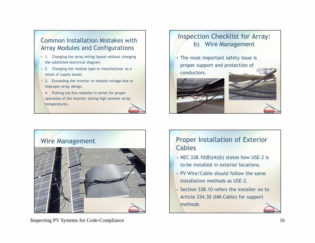
Common Installation Mistakes with Array Modules and Configurations• 1. Changing the array wiring layout without changing
the submitted electrical diagram.
• 2. Changing the module type or manufacturer as a
result of supply issues.
• 3. Exceeding the inverter or module voltage due to improper array design.
• 4. Putting too few modules in series for proper operation of the inverter during high summer array
temperatures.
• The most important safety issue is proper support and protection of conductors.
Inspection Checklist for Array:b) Wire Management
Wire Management Proper Installation of Exterior Cables• NEC 338.10(B)(4)(b) states how USE-2 is
to be installed in exterior locations.
• PV Wire/Cable should follow the same installation methods as USE-2.
• Section 338.10 refers the installer on to Article 334.30 (NM Cable) for support methods

Inspecting PV Systems for Code-Compliance 17
Proper Installation of Exterior Cables—Article 334.30
• 1. Secured by staples, cable ties, straps, hangers, or similar fittings at intervals that do not exceed 4.5 feet
• 2. Secured within 12 inches of each box, cabinet, conduit body,
or other termination
• 3. Sections protected from physical damage by raceway shall not
be required to be secured within the raceway
• 4. Cable shall closely follow the surface of the building finish or
of running boards ((NEC 334.15)—the analogous installation for USE-
2 in PV arrays is for the conductors to follow support rails or module
extrusions)
• 5. Protected from physical damage by raceway when necessary
Wire Management—Proper
Wire Management—Room for Improvement
Wire Management—Support?

Inspecting PV Systems for Code-Compliance 18
Common Installation Mistakes with Wire Management• 1. Not enough supports to properly control cable.
• 2. Conductors touching roof or other abrasive surfaces exposing them to physical damage.
• 3. Conductors not supported within 12 inches of
boxes or fittings.
• 4. Not supporting raceways at proper intervals.
• 5. Multiple cables entering a single conductor cable
gland (aka cord grip)
• 6. Not following support members with conductors.
Proper cable glands into Combiner Box
Common Installation Mistakes with Wire Management—cont.• 7. Pulling cable ties too tight or leaving them too
loose.
• 8. Not fully engaging plug connectors.
• 9. Bending conductors too close to connectors.
• 10. Bending USE-2 cable tighter than allowable bending radius.
• 11. Plug connectors on non-locking connectors not
fully engaged
Wire Management—Physical Damage

Inspecting PV Systems for Code-Compliance 19
Wire Managementcount the bad ideas
Wire Management—wire bending radius
Wire Management—plug engagement Wire Management—Follow structural members & What the…?

Inspecting PV Systems for Code-Compliance 20
What you can’t see won’t hurt you??
Inspection Checklist for Array:c) Module and Array Grounding
• Most common concern of field inspectors.
• Ungrounded module frames
are a potential safety hazard.
• All array metal “likely to
become energized” must be
properly bonded together and grounded with lugs on each
module and mounting rails or
some equivalent equipment
grounding method.
Wrongconnectors
Module bonding and grounding methods
• 1. Some modules are designed to be grounded using a stainless-steel thread-forming screw threaded into the module frame
holding the EGC at a grounding symbol. An isolating washer, such
as a stainless cup washer is often used to isolate the copper
conductor from the aluminum frame to prevent galvanic corrosion.
• 2. Some modules can be grounded to their mounting structures
with stainless steel star washers placed between the module and the support structure. This creates an electrical bond while
isolating the aluminum frame from dissimilar materials such as
galvanized steel. The EGC is attached to an electrically
continuous support member with a properly installed grounding lug.
Module bonding and grounding methods—cont.
• 3. Some modules can be grounded by properly installing a properly rated lay-in lug to the either the grounding point on the module, or
any unused mounting hole. The EGC is run through this lay-in lug to
bond the modules together.
• 4. For specific module mounting products (e.g. UniRac, ProSolar,
DPW, etc…), there exists listed grounding clips to bond typical
aluminum framed modules to the mounting structure. Only the
proper clip can be used with each mounting structure. This allows the EGC to be connected to the electrically continuous rail. This method
is consistent the NEC 690.43 and NEC 250.136.
• 5. Some modules can be grounded together using serrated clips that hold the module to the support structure and electrically bond
with the module. One lug on any module can ground a whole row.

Inspecting PV Systems for Code-Compliance 21
Early module and structure grounding improvements
Identifying Grounding Clips
Notice slight gap caused by properly installed clip.
Common Installation Mistakes with Module and Array Grounding• 1. Not installing a grounding conductor on the array at all.
• 2. Using cad-plated Tek screws to fasten ground wires or lugs
to modules.
• 3. Using indoor-rated grounding lugs on PV modules and
support structures.
• 4. Not protecting EGCs smaller than 6 AWG from physical damage.
• 5. Allowing copper EGC to come in contact with the aluminum
rails and module frames.
• 6. Assuming that simply bolting aluminum frames to support
structures provides effective grounding.

Inspecting PV Systems for Code-Compliance 22
Nice Lugs! (poor fasteners)
Improper Cad Tek screw used to hold lug
Indoor lugs and Tek screws
Aluminum bolted to steel without isolation washers and no effective bond
Grounding Hardware and Components
Indoor lug and Tek screw
Stainless hardware looks like new
Galvanized washer showing galvanic corrosion with aluminum contact
Inspection Checklist for Array:d) Electrical enclosures on Roof Accessible and Connections Suitable for the Environment
• NEC 690.34 Access to Boxes. Junction, pull, and outlet boxes located behind modules or panels shall
be so installed that the wiring contained in them can be rendered accessible directly or by displacement of
a module(s) or panel(s) secured by removable fasteners and connected by a flexible wiring system.

Inspecting PV Systems for Code-Compliance 23
Rooftop j-boxes in compliance with 690.34
Junction Boxes• Connection between
conductors in an outdoor location generally must be done within a rainproof junction box, NEMA 3R, or 4 (unless with approved connector)
• Junction boxes are commonly used to transition conductors from exterior to conduit conductors and for combining array source circuits.
Waterproof wirenuts must be in j-boxes
Improper Connections
Dry wirenut and not in a j-box
Wire twisted together, wrapped in tape, and in the sun
Ratings and locations of Disconnects
NEMA 3R disconnect on sloped roof designed for vertical mounting only
Black cover to shield improperly installed switch only served to make switch invisible

Inspecting PV Systems for Code-Compliance 24
Ratings and locations of Combiner Boxes
NEMA 4 Combiner Box with disconnect built-in. Designed for horizontal or vertical mounting
Common Installation Mistakes with Electrical Boxes, Conduit Bodies, and Disconnecting Means• 1. Installing disconnects rated for vertical installation in a non-
vertical application.
• 2. Installing improperly rated fuses in source combiners and
fused disconnects.
• 3. Covering boxes or conduit bodies making them nearly
inaccessible for service.
• 4. Not following manufacturer’s directions for wiring
disconnect for 600 Vdc ratings.
• 5. Installing dry wire nuts in wet locations and inside boxes
that get wet routinely.
• 6. Using improper fittings to bring conductors into exterior
boxes.
Many disconnects like these require the ungrounded conductor to be broken twice in series to get the 600Vdc rating
CorrectIncorrectBreaking of grounded conductor
Correct Fuses

Inspecting PV Systems for Code-Compliance 25
Correct FusesCorrect Fuses ??
Correct Fuses ??Correct Fusesand Terminals ?

Inspecting PV Systems for Code-Compliance 26
Proper Current Rating? Proper Current Rating?
Properly Rated Disconnects and Inverters
Inspection Checklist for Array:e) Array Fastened and Sealed According To Attachment Detail
• Roof penetrations must be properly sealed to preclude leakage.
• Do a hand pull test on a sample of lag screw attachments to make sure they are secured to rafters.
• Look in attic to see if lags are visible.

Inspecting PV Systems for Code-Compliance 27
Proper and Improper FlashingCommon Installation Mistakes with Mounting Systems:
• 1. Not using supplied or specified hardware with the mounting systems.
• 2. Substituting Unistrut for special manufactured aluminum
extrusions.
• 3. Not installing flashings properly.
• 4. Not using the correct roof adhesives for the specific type of roof.
• 5. Not attaching proper lag screws to roofing members.
• 6. Not drilling proper pilot holes for lag screws and missing or
splitting roofing members.
Inspection Checklist for Array:f) Conductor Ratings and Sizes• Exposed Array Conductors—The only single-
conductor cables allowed in 690.31(B) are USE-2
and PV Wire (Cable).
• Conductors in raceways on rooftops—Table
310.15(B)(2)(a) adds an additional 14°C-30°C to
the ambient temperature. These high
temperatures nearly always limit ampacity
below the terminal temperature ampacity.
Conduit Exposed to Sunlight Above Rooftops —Table 310.15(B)(2)(a)

Inspecting PV Systems for Code-Compliance 28
Common Installation Mistakes with Conductors:• 1. Not accounting for high operating temperatures in
rooftop conduit.
• 2. Specifying THHN conductors rather than wet rated
conductors in drawings where raceways are clearly located outdoors.
• 3. Specifying or installing THWN conductors in
raceways that may exceed 60°C without properly correcting the THWN conductors for this temperature.
Incorrect conductors and roof plumbing into combiner box
Improperly Rated ConductorsTHWN conductors outside conduit
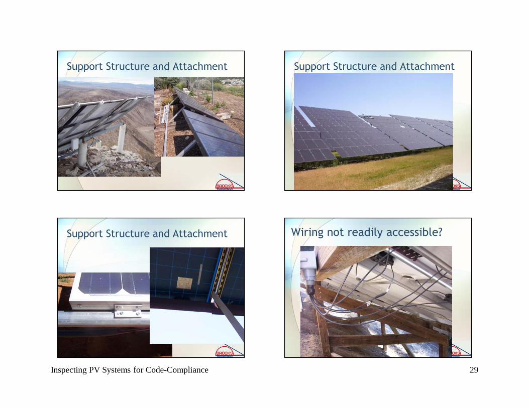
Section 2. Specifics For Ground-Mounted Arrays
• a) Foundation and mounting structure review
• b) Electrical bonding of structural elements
• c) Additional array electrode [690.47(D)]
• d) Attachment method according to plans
• e) Wiring not readily accessible
Inspecting PV Systems for Code-Compliance 29
Support Structure and Attachment Support Structure and Attachment
Support Structure and Attachment Wiring not readily accessible?

Inspecting PV Systems for Code-Compliance 30
Readily accessible or not? Common Installation Mistakes with Ground Mounting Systems:
• 1. Not using supplied or specified hardware with the mounting systems.
• 2. Substituting Unistrut for special manufactured aluminum extrusions.
• 3. No bonding of support structure or discontinuous grounding of support structure.
• 4. Dissimilar metals in contact with one another (e.g. aluminum and
galvanized steel).
• 5. No bonding of aluminum structural elements to steel structural
elements.
• 6. Array wiring readily accessible to other than authorized personnel.
Section 3. Appropriate signs installed
•Sign construction
•Photovoltaic Power Source
•AC point of connection
•alternative power system
Sign Construction• The NEC is not extremely specific about what signs
should be made of.
• NEC 110.21 states, “The marking shall be of
sufficient durability to withstand the environment
involved.”
• Electrical industry standards for outdoor signs is
that signs should be metal or plastic with engraved
or machine printed letters, or electro-photo
plating, in a contrasting color to the sign
background.

Inspecting PV Systems for Code-Compliance 31
Indoor signs may allow more variety of construction
Photovoltaic Power Source Sign
Signs and LabelsAC Point of Interconnection

Inspecting PV Systems for Code-Compliance 32
Signs and Labelsit is possible to have too many.
Section 4. Check that equipment ratings are consistent with application and signs
Inverter LabelsDisconnects consistent with requirements

Inspecting PV Systems for Code-Compliance 33
Guts—show and tell Guts—show and tell
Guts—show and tellGuts—show and tell

Inspecting PV Systems for Code-Compliance 34
Good Installation Practices Good Installation Practices
Good Installation Practices Good Installation Practices

Inspecting PV Systems for Code-Compliance 35
Nice Work Nice Work
Nice Work Nice Work

Inspecting PV Systems for Code-Compliance 36
Nice Work Nice Work
Nice Work
Expedited Permit Process for PV Systems
available at www. Solarabcs.org/permitting
Expedited Permit Process for PV Systems
available at www. Solarabcs.org/permitting

Inspecting PV Systems for Code-Compliance 37
Why do we need Permit Guidelines?
• Variations in compliance requirements—some are
insufficient to protect the public, others may not
be consistent with established standards.
• Need a predictable process with uniform
enforcement of code requirements for
jurisdictional authorities and installing
contractors.
Required Information for Permit• Site plan showing location of major components on the property.
This drawing need not be exactly to scale, but it should represent
relative location of components at site (see supplied example site
plan). PV arrays on dwellings with a 3’ perimeter space at ridge
and sides do not need fire service approval.
• Electrical diagram showing PV array configuration, wiring system,
overcurrent protection, inverter, disconnects, required signs, and
ac connection to building (see supplied standard electrical diagram).
• Specification sheets and installation manuals (if available) for all
manufactured components including, but not limited to, PV modules, inverter(s), combiner box, disconnects, and mounting
system.
Step 1: Structural Review of PV Array Mounting System
• Is the array to be mounted on a defined, permitted roof structure? Yes/No (structure meets modern codes)
• If No due to non-compliant roof or ground mount, submit completed worksheet for roof structure WKS1.
Roof Information:
• Is the roofing type lightweight (Yes = composition, lightweight masonry, metal, etc…)_____________− If No, submit completed worksheet for roof structure
WKS1 (No = heavy masonry, slate, etc…).
• Does the roof have a single roof covering? Yes/No− If No, submit completed worksheet for roof structure
WKS1.
• Provide method and type of weatherproofing roof penetrations (e.g. flashing, caulk).____________

Inspecting PV Systems for Code-Compliance 38
Mounting System Information:
• The mounting structure is an engineered
product designed to mount PV modules?
Yes/No− If No, provide details of structural attachment
certified by a design professional.
• For manufactured mounting systems, fill out
information on the mounting system below:
Mounting System Information:a) Mounting System Manufacturer ___________Product Name and
Model#_____________
b) Total Weight of PV Modules and Rails ___________lbs
c) Total Number of Attachment Points____________
d) Weight per Attachment Point (b÷c)_________________lbs (if greater
than 45 lbs, see WKS1)
e) Maximum Spacing Between Attachment Points on a Rail
______________inches (see product manual for maximum spacing
allowed based on maximum design wind speed)
f) Total Surface Area of PV Modules (square feet)_________________ ft2
g) Distributed Weight of PV Module on Roof (b÷f)_______________ lbs/ft2
− If distributed weight of the PV system is greater than 5 lbs/ft2, see WKS1.
Step 2: Electrical Review of PV System (Calculations for Electrical Diagram)• In order for a PV system to be considered for an
expedited permit process, the following must apply:1. PV modules, utility-interactive inverters, and combiner boxes are
identified for use in PV systems.2. The PV array is composed of 4 series strings or less3. The Inverter has a continuous power output 13,440 Watts or less4. The ac interconnection point is on the load side of service
disconnecting means (690.64(B)).5. The electrical diagram (E1.1) can be used to accurately represent the
PV system.
Site Diagram
• Drawing does not need to be to scale, but it should basically show were the major components are located.
• If array is ground mounted, it should show that it conforms with allowable setbacks.

Inspecting PV Systems for Code-Compliance 39
One-line Diagram
• Should have sufficient detail to call out the
electrical components, the wire types and
sizes, number of conductors, and conduit type
and size where needed.
• Should include information about PV modules
and inverter(s).
• Should include information about utility
disconnecting means (required by many
utilities).

Inspecting PV Systems for Code-Compliance 40
Major Component and Array Electrical Information
• Inverter information
• Module information
• Combiner Box
• Disconnects
Inverter information
• Model number and manufacturer’s “cut sheets”
for the specific model.
• Listing—is the inverter listed to UL1741 and
labeled “Utility-Interactive”? For a current list of
compliant inverters, visit the California Solar
Program website. www.gosolarcalifornia.com
• Maximum continuous output power at 40oC

Inspecting PV Systems for Code-Compliance 41
Module information
• Manufacturer’s “cut sheets” for the specific
model.
• Listing. The module should be listed to UL 1703.
For a current list of modules that are listed to UL
1703, visit the California website.
www.gosolarcalifornia.com
• Listing label information
Typical PV Module Label
Array electrical information
• Number of modules in series
• Array operating voltage
• Array operating current
• Maximum system voltage
• Array short circuit current