purification of bismuthinite concentrate by selective ...¬cation of bismuthinite concentrate by...
TRANSCRIPT
Hydrometallurgy 154 (2015) 95–101
Contents lists available at ScienceDirect
Hydrometallurgy
j ourna l homepage: www.e lsev ie r .com/ locate /hydromet
Purification of bismuthinite concentrate by selective electro-oxidationof molybdenite
Zhan-fang Cao a,⁎, Ming-ming Wang a, Hong Zhong a,⁎, Na Chen a, Liu-yin Xia b, Fan Fan a,Guang-yi Liu a, Shuai Wang a
a College of Chemistry and Chemical Engineering, Central South University, Changsha, Hunan 410083, PR Chinab Surface Science Western, Research Park, University of Western Ontario, 999 Collip Cir., London, ON, Canada
⁎ Corresponding authors.E-mail address: [email protected] (Z. Cao).
http://dx.doi.org/10.1016/j.hydromet.2015.04.0120304-386X/© 2015 Elsevier B.V. All rights reserved.
a b s t r a c t
a r t i c l e i n f oArticle history:Received 5 July 2014Received in revised form 31 March 2015Accepted 5 April 2015Available online 11 April 2015
Keywords:MolybdeniteBismuthiniteElectro-oxidationSeparationCyclic voltammetry
The flotation separation is the general method to recover molybdenite from a concentration containing molyb-denite and bismuthinite, although thewhole circuit could be long and complicated. In this paper, a novel selectiveelectro-oxidation of molybdenite process has been introduced and systematically investigated for bismuthinitepurification. It was found that Mo could be selectively separated by the electro-oxidationmethod under the con-ditions of pH not less than 9.0 and the applied potential at between 3.0 V and 4.0 V, by this circumstance Bi washard to extract. The effects of NaCl concentration, liquid/solid ratio and stirring speed on electro-oxidationleachingwere investigated. Optimum leaching conditions were found as follows: operated at room temperature,leaching time= 2.5 h, NaCl concentration= 4mol/L, pH= 9–10, applied potential = 3.4 V, liquid/solid ratio=30mL/g, stirring speed=400 rpm. Under these conditions, Mo extraction yield was obtained at 98.4% and 99.3%of Bi remained in the residue. The chlorine evolution reaction at the anodewhichwas effected by leaching pHwasstudied by linear scan voltammetry. Mechanism of electro-oxidation leaching of Mo was studied by cyclic volt-ammetry. Furthermore, the mass transfer of Mo from leachate to organic phase was introduced, and the twophase transfer could obtain as high as 99.6%.
© 2015 Elsevier B.V. All rights reserved.
1. Introduction
In China, bismuthinite associated with low grade molybdenite isquite abundant. At present, a flotation process is the main method ofMo separation from Bi concentrate (Shang et al., 2010; Liu, 2011). Inthe conventional froth flotation process, most of the molybdenite floatsalong with the Bi sulfides, forming Bi–Mo concentrates. This streamwould ultimately be turned into a higher grade bismuthinite concen-trate after going through differential flotation. To acquire the highgrade bismuthinite, Mo removal is necessary, therefore the whole flota-tion process would be inevitably long and complicated (Guo and Zhou,2009). In cases where bismuthinite and molybdenite are intergrownclosely, it is especially difficult to remove Mo from the concentrateonly processed by froth flotation.
Other methods used to separate Mo from polymetallic ores havebeen reported (Lee et al., 1980; Feng et al., 2010; Tang et al., 2011;Warren and Mounsey, 1983). Selective separation of Mo as volatile ha-lides from deep-sea ferromanganese modules can be achieved by thesulfation of the ground nodule material with a gas mixture of SO2 and
O2 at elevated temperatures, which results in the sublimation of Mo inthe form of MoCl4 and MoO2Cl2 (Lee et al., 1980). Some authors haveproposed the separation of Mo from the Cu–Mo collective concentrate,and the process flow includes three steps: heating pretreatment, sepa-rating Cu and Mo after grinding and finally regrinding concentration(Feng et al., 2010). The adoption of two-stage leaching at different tem-peratures to selectively recover Mo from alkaline Bi smelting slag hasbeen reported, and the leaching efficiency of Mo could reach 94.51%under optimum conditions (Tang et al., 2011). Sodium hypochloritewas employed to selectively leach Mo from Cu/Mo sulfide minerals(Warren and Mounsey, 1983). The separation of Mo from sulfide con-centrate by electro-oxidation has been reported in a few articles(Darjaa et al., 2000; Cao et al., 2010).
As a relatively novel technology in hydrometallurgy, electro-oxidation combines the leaching of polymetallic concentrates whichcan be oxidized by a current at the anode or oxidants generated at theanode with the electrowinning of metals at the cathode in acid solu-tions. The oxidants generated at the anode usually refer to chlorine ox-idants which come from electrolysis of such acid chloride solutions asNaCl solution and KCl solution at the anode and electro-oxidation ismainly used to leach metal sulfides (Brace, 1969; Kruesi, 1972;Everett, 1978; Qiu, 1999; Yang and Zhang, 2000). Application ofelectro-oxidation to treat bismuthinite has been reported in some
96 Z. Cao et al. / Hydrometallurgy 154 (2015) 95–101
articles, and the leaching of bismuthinite is basically considered as a re-sult of the oxidation of concentrates by chlorine oxidants and Fe3+ gen-erated at the anode (Wang et al., 1995a,b; Liu, 1998). Furthermore,formation and oxidation mechanisms of sulfur in the process of slurryelectrolysis on bismuthinite have been investigated to make bettersense of the electro-oxidation process of bismuthinite (Wang et al.,2002). However, all the articles related to the electro-oxidationof bismuthinite focused on the leaching of Bi but not the impurityremoval.
The oxidation sequence of metal sulfides at the anode (Qiu, 1999)makes it possible to selectively separate Mo from bismuthinite. NaClOhas been especially recognized as the oxidant which can selectivelyoxidize molybdenite from polymetallic sulfides under appropriate con-ditions (Xiang, 2002), which means selective leaching of Mo frombismuthinite concentrate may be achieved by converting as much Cl−
as possible into ClO− at the anode in the electrically assisted leachingthrough altering relevant process parameters. This paper investigatedthe effects of five process parameters, namely pH, applied potential,NaCl concentration, stirring speed and liquid/solid ratio, on the leachingof Mo from bismuthinite. Cyclic voltammetry was adopted to study themechanism of the electro-oxidation of Mo from bismuthinite concen-trates. With solvent extraction adopted to recover Mo from leachate,the study on how to transfer Mo from leachate to organic phase effi-ciently was carried out.
2. Experimental
2.1. Concentrate sample, reagents and electro-oxidation leaching processsetup
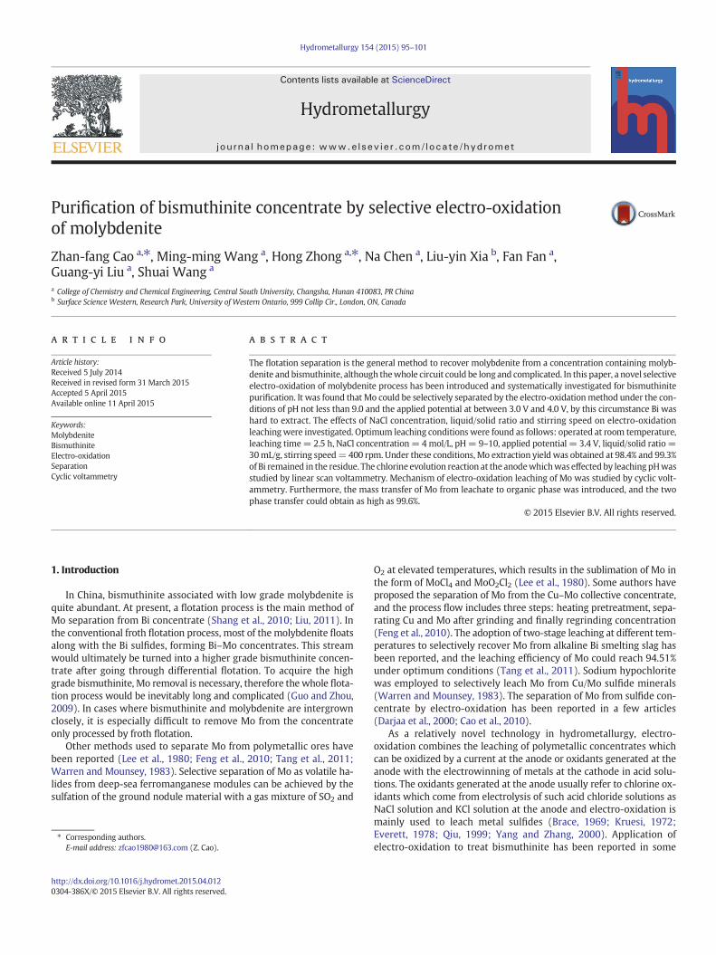
The concentrate sample, of which the XRF result is listed, is as fol-lows: Mo 5.26%, S 18.88%, Bi 38.12%, Cu 3.35%, Fe 8.70%, Ca 2.91%, Si3.89%, Al 1.24%, O 10.44%, were provided by Shizhuyuan Mine, HunanProvince (EDX1800B X-ray Fluorescence meter produced by Skyray In-strument Co., Ltd., Kunshan, China). The particle size ranged from 10 μmto 100 μm and 83% less than 40 μm. X-ray diffraction of the concentratesample (Fig. 1) shows that bismuthinite and molybdenite were themajor phases (Rigaku 2500 X-ray Diffract meter produced by RigakuCorporation, Japan). Except for N235 (tertiary amine R3N, R = C8–
C10), sec-caprylic alcohol and kerosene, which were industrial gradeand water was tap-water, all other reagents used in the experimentswere of chemical grade purity. A self-made septum-free electrolyticbath fitted with pH and temperature detectors was chosen, and howDSA anodes (dimensionally stable anode, RuO2, IrO2, SnO2 coatedmesh electrode, 100 mm × 100 mm) and iron cathodes (low-carbonsteel mesh electrode, 100 mm × 100 mm) were fixed to the bath is
10 20 30 40 50 60 70 800
500
1000
1500
2000
2500
• MoS2
♦ Bi2S
3
♦
♦
♦♦ •
Inte
nsit
y (a
.u.)
2θ/degree
•
♦
concentrate sample
Fig. 1. X-ray diffraction pattern of the concentrate sample.
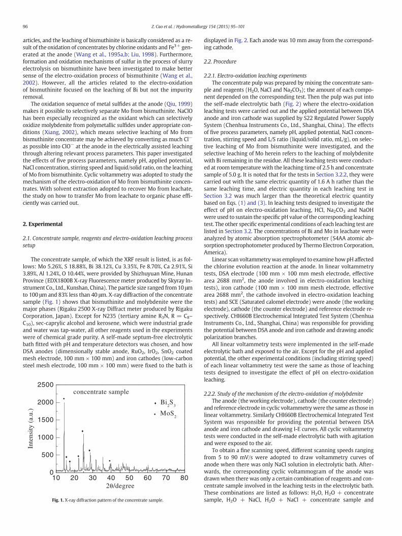
displayed in Fig. 2. Each anode was 10 mm away from the correspond-ing cathode.
2.2. Procedure
2.2.1. Electro-oxidation leaching experimentsThe concentrate pulp was prepared by mixing the concentrate sam-
ple and reagents (H2O, NaCl and Na2CO3); the amount of each compo-nent depended on the corresponding test. Then the pulp was put intothe self-made electrolytic bath (Fig. 2) where the electro-oxidationleaching tests were carried out and the applied potential between DSAanode and iron cathode was supplied by S22 Regulated Power SupplySystem (Chenhua Instruments Co., Ltd., Shanghai, China). The effectsof five process parameters, namely pH, applied potential, NaCl concen-tration, stirring speed and L/S ratio (liquid/solid ratio, mL/g), on selec-tive leaching of Mo from bismuthinite were investigated, and theselective leaching of Mo herein refers to the leaching of molybdenitewith Bi remaining in the residue. All these leaching tests were conduct-ed at room temperature with the leaching time of 2.5 h and concentratesample of 5.0 g. It is noted that for the tests in Section 3.2.2, they werecarried out with the same electric quantity of 1.6 A h rather than thesame leaching time, and electric quantity in each leaching test inSection 3.2 was much larger than the theoretical electric quantitybased on Eqs. (1) and (3). In leaching tests designed to investigate theeffect of pH on electro-oxidation leaching, HCl, Na2CO3 and NaOHwere used to sustain the specific pH value of the corresponding leachingtest. The other specific experimental conditions of each leaching test arelisted in Section 3.2. The concentrations of Bi and Mo in leachate wereanalyzed by atomic absorption spectrophotometer (S4AA atomic ab-sorption spectrophotometer produced by Thermo Electron Corporation,America).
Linear scan voltammetrywas employed to examine howpH affectedthe chlorine evolution reaction at the anode. In linear voltammetrytests, DSA electrode (100 mm × 100 mm mesh electrode, effectivearea 2688 mm2, the anode involved in electro-oxidation leachingtests), iron cathode (100 mm × 100 mm mesh electrode, effectivearea 2688 mm2, the cathode involved in electro-oxidation leachingtests) and SCE (Saturated calomel electrode) were anode (the workingelectrode), cathode (the counter electrode) and reference electrode re-spectively. CHI660B Electrochemical Integrated Test System (ChenhuaInstruments Co., Ltd., Shanghai, China) was responsible for providingthe potential between DSA anode and iron cathode and drawing anodicpolarization branches.
All linear voltammetry tests were implemented in the self-madeelectrolytic bath and exposed to the air. Except for the pH and appliedpotential, the other experimental conditions (including stirring speed)of each linear voltammetry test were the same as those of leachingtests designed to investigate the effect of pH on electro-oxidationleaching.
2.2.2. Study of the mechanism of the electro-oxidation of molybdeniteThe anode (the working electrode), cathode (the counter electrode)
and reference electrode in cyclic voltammetrywere the same as those inlinear voltammetry. Similarly CHI660B Electrochemical Integrated TestSystem was responsible for providing the potential between DSAanode and iron cathode and drawing I-E curves. All cyclic voltammetrytests were conducted in the self-made electrolytic bath with agitationand were exposed to the air.
To obtain a fine scanning speed, different scanning speeds rangingfrom 5 to 90 mV/s were adopted to draw voltammetry curves ofanode when there was only NaCl solution in electrolytic bath. After-wards, the corresponding cyclic voltammogram of the anode wasdrawnwhen there was only a certain combination of reagents and con-centrate sample involved in the leaching tests in the electrolytic bath.These combinations are listed as follows: H2O, H2O + concentratesample, H2O + NaCl, H2O + NaCl + concentrate sample and
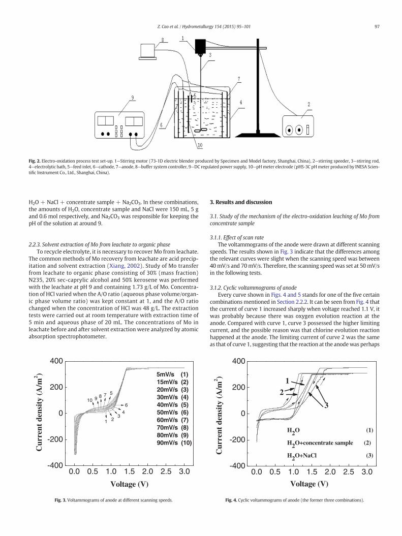
Fig. 2. Electro-oxidation process test set-up. 1—Stirring motor (73-1D electric blender produced by Specimen and Model factory, Shanghai, China), 2—stirring speeder, 3—stirring rod,4—electrolytic bath, 5—feed inlet, 6—cathode, 7—anode, 8—buffer system controller, 9—DC regulated power supply, 10—pHmeter electrode (pHS-3C pHmeter produced by INESA Scien-tific Instrument Co., Ltd., Shanghai, China).
97Z. Cao et al. / Hydrometallurgy 154 (2015) 95–101
H2O + NaCl + concentrate sample + Na2CO3. In these combinations,the amounts of H2O, concentrate sample and NaCl were 150 mL, 5 gand 0.6 mol respectively, and Na2CO3 was responsible for keeping thepH of the solution at around 9.
2.2.3. Solvent extraction of Mo from leachate to organic phaseTo recycle electrolyte, it is necessary to recover Mo from leachate.
The common methods of Mo recovery from leachate are acid precip-itation and solvent extraction (Xiang, 2002). Study of Mo transferfrom leachate to organic phase consisting of 30% (mass fraction)N235, 20% sec-caprylic alcohol and 50% kerosene was performedwith the leachate at pH 9 and containing 1.73 g/L of Mo. Concentra-tion of HCl varied when the A/O ratio (aqueous phase volume/organ-ic phase volume ratio) was kept constant at 1, and the A/O ratiochanged when the concentration of HCl was 48 g/L. The extractiontests were carried out at room temperature with extraction time of5 min and aqueous phase of 20 mL. The concentrations of Mo inleachate before and after solvent extraction were analyzed by atomicabsorption spectrophotometer.
0.0 0.5 1.0 1.5 2.0 2.5 3.0-400
-200
0
200
400
10 9 8 7 5
6
43
2
Cur
rent
den
sity
(A
/m2 )
Voltage (V)
5mV/s (1)15mV/s (2) 20mV/s (3) 30mV/s (4) 40mV/s (5) 50mV/s (6) 60mV/s (7) 70mV/s (8) 80mV/s (9) 90mV/s (10)
1
Fig. 3. Voltammograms of anode at different scanning speeds.
3. Results and discussion
3.1. Study of the mechanism of the electro-oxidation leaching of Mo fromconcentrate sample
3.1.1. Effect of scan rateThe voltammograms of the anode were drawn at different scanning
speeds. The results shown in Fig. 3 indicate that the differences amongthe relevant curves were slight when the scanning speed was between40mV/s and 70mV/s. Therefore, the scanning speedwas set at 50mV/sin the following tests.
3.1.2. Cyclic voltammograms of anodeEvery curve shown in Figs. 4 and 5 stands for one of the five certain
combinations mentioned in Section 2.2.2. It can be seen from Fig. 4 thatthe current of curve 1 increased sharply when voltage reached 1.1 V, itwas probably because there was oxygen evolution reaction at theanode. Compared with curve 1, curve 3 possessed the higher limitingcurrent, and the possible reason was that chlorine evolution reactionhappened at the anode. The limiting current of curve 2 was the sameas that of curve 1, suggesting that the reaction at the anodewas perhaps
0.0 0.5 1.0 1.5 2.0 2.5 3.0-400
-200
0
200
400
Cur
rent
den
sity
(A
/m2 )
H2O (1)
H2O+concentrate sample (2)
H2O+NaCl (3)
3
2
1
Voltage (V)
Fig. 4. Cyclic voltammograms of anode (the former three combinations).
0.0 0.5 1.0 1.5 2.0 2.5 3.0-400
-200
0
200
400
3
2
1
H2O+NaCl (1)
H2O+NaCl+concentrate sample (2)
H2O+NaCl+concentrate sample+Na
2CO
3 (3)
Voltage (V)
Cur
rent
den
sity
(A
/m2 )
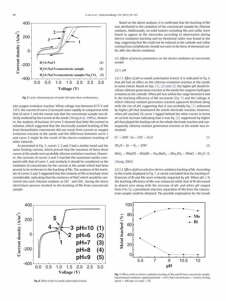
Fig. 5. Cyclic voltammograms of anode (the latter three combinations).
98 Z. Cao et al. / Hydrometallurgy 154 (2015) 95–101
also oxygen evolution reaction. When voltage was between 0.75 V and1.0 V, the current of curve 2 increased more rapidly in comparison withthat of curve 1 and the reason was that the concentrate sample was di-rectly oxidized by the current at the anode (Wang et al., 1995a). Howev-er, the analysis of leachate of curve 2 showed that little Mo existed insolution, which suggested that the electrically assisted leaching of Mofrom bismuthinite concentrate did not result from current or oxygenevolution reaction at the anode and the difference between curve 1and curve 2 might be the result of the electro-oxidation leaching ofother minerals.
As presented in Fig. 5, curves 1, 2 and 3 had a similar trend and thesame limiting current, which proved that the reactions of these threecurves at the anodewere probably chlorine evolution reactions. Howev-er, the currents of curves 2 and 3 reached the maximum earlier com-pared with that of curve 1, and similarly it should be considered as theoxidation of concentrates by the current at the anode which had beenproved to be irrelevant to the leaching of Mo. The analyses of the leach-ate of curves 2 and 3 suggested that the contents of Mo in leachate wereconsiderable, indicating that the existence of NaCl whichwould be con-verted into such chlorine oxidants as ClO− and ClO3
− during the slurryelectrolysis process resulted in the leaching of Mo from concentratesample.
0.0 0.5 1.0 1.5 2.0 2.5 3.0-400
-200
0
200
400
Cur
rent
den
sity
(A
/m2 )
Voltage (V)
pH=10 (1)pH=6 (2)pH=7 (3)pH=8 (4)pH=9 (5)
1234
5
Fig. 6. Effect of pH on anodic polarization branch.
Based on the above analyses, it is confirmed that the leaching of Mowas attributed to the oxidation of the concentrate sample by chlorineoxidants. Additionally, no solid matters including Mo and sulfur werefound to appear at the electrodes according to observation duringelectro-oxidation leaching and no elemental sulfur was found in theslag, suggesting that Mo could not be reduced at the cathode and sulfurcoming frommolybdenite should not exist in the form of elemental sul-fur after the electro-oxidation.
3.2. Effects of process parameters on the electro-oxidation of concentratesample
3.2.1. pH
3.2.1.1. Effect of pH on anodic polarization branch. It is indicated in Fig. 6that pH had an effect on the chlorine-evolution reaction at the anodeto some extent. Based on Eqs. (1), (2) and (3), the higher pH should fa-cilitate chlorine generation reaction at the anode but suppress hydrogenevolution at the cathode.When pHwaswithin the range between 6 and9, the leaching efficiency of Mo increased (Fig. 7) and the voltage atwhich chlorine oxidant generation reaction appeared declined alongwith the rise of pH, suggesting that it was probably Eq. (1) enhancedby higher pH that dominated the whole electrode reaction. However,when pH reached 10, curve 1 lagged behind the other curves in termsof current increase indicating that it was Eq. (2) suppressed by higherpH that played the leading role in thewhole electrode reaction and con-sequently chlorine oxidant generation reaction at the anode was re-strained.
Cl‐ þ 2OH‐‐2e ¼ ClO‐ þH2O ð1Þ
2H2Oþ 2e ¼ H2 þ 2OH‐ ð2Þ
MoS2 þ 9NaClOþ 6NaOH ¼ Na2MoO4 þ 2Na2SO4 þ 9NaClþ 3H2O:ð3Þ
(Xiang, 2002)
3.2.1.2. Effect of pH on selective electro-oxidation leaching ofMo.Accordingto the results displayed in Fig. 7, it can be concluded that the leaching ef-ficiencies of Bi and Mo were evidently impacted by pH. When pH ≤ 9,the leaching efficiency of Mo was enhanced while that of Bi decreasedto almost zero along with the increase of pH, and when pH rangedfrom 9 to 12, a prominent selective separation of Mo from the concen-trate sample could be obtained. The possible explanation for the trends
5.5 7 9 10.5 120
20
40
60
80
100
Met
al le
ache
d (%
)
pH
Mo Bi
Fig. 7. Effect of pH on electro-oxidation leaching of Mo and Bi from concentrate sample.Experimental conditions: appliedpotential=4.0 V,NaCl concentration=4mol/L, stirringspeed = 300 rpm, L/S ratio = 50.
1.5 2.0 2.5 3.0 3.5 4.0 4.5 5.0 5.5 6.00
20
40
60
80
100 Mo Bi
Met
al le
ache
d (%
)
Applied potential (V)
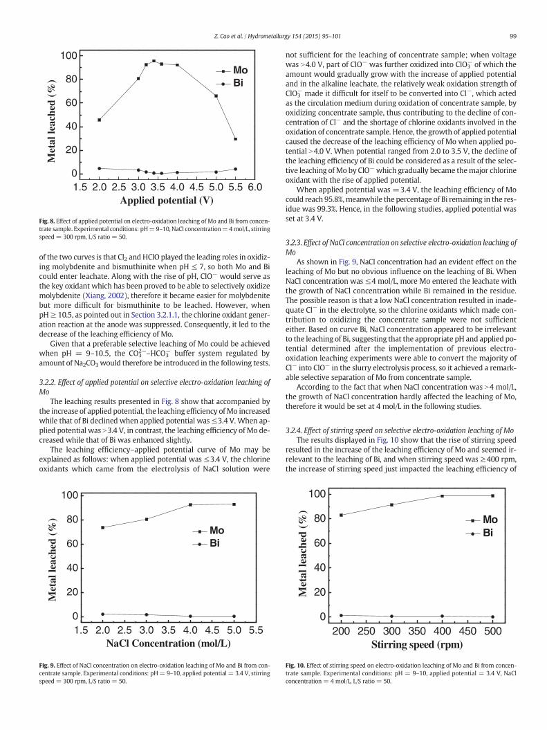
Fig. 8. Effect of applied potential on electro-oxidation leaching of Mo and Bi from concen-trate sample. Experimental conditions: pH=9–10, NaCl concentration=4mol/L, stirringspeed = 300 rpm, L/S ratio = 50.
99Z. Cao et al. / Hydrometallurgy 154 (2015) 95–101
of the two curves is that Cl2 and HClO played the leading roles in oxidiz-ing molybdenite and bismuthinite when pH ≤ 7, so both Mo and Bicould enter leachate. Along with the rise of pH, ClO− would serve asthe key oxidant which has been proved to be able to selectively oxidizemolybdenite (Xiang, 2002), therefore it became easier for molybdenitebut more difficult for bismuthinite to be leached. However, whenpH≥ 10.5, as pointed out in Section 3.2.1.1, the chlorine oxidant gener-ation reaction at the anode was suppressed. Consequently, it led to thedecrease of the leaching efficiency of Mo.
Given that a preferable selective leaching of Mo could be achievedwhen pH = 9–10.5, the CO3
2—–HCO3− buffer system regulated by
amount of Na2CO3would therefore be introduced in the following tests.
3.2.2. Effect of applied potential on selective electro-oxidation leaching ofMo
The leaching results presented in Fig. 8 show that accompanied bythe increase of applied potential, the leaching efficiency ofMo increasedwhile that of Bi declined when applied potential was≤3.4 V. When ap-plied potential was N3.4 V, in contrast, the leaching efficiency of Mo de-creased while that of Bi was enhanced slightly.
The leaching efficiency–applied potential curve of Mo may beexplained as follows: when applied potential was ≤3.4 V, the chlorineoxidants which came from the electrolysis of NaCl solution were
1.5 2.0 2.5 3.0 3.5 4.0 4.5 5.0 5.50
20
40
60
80
100
Met
al le
ache
d (%
)
NaCl Concentration (mol/L)
Mo Bi
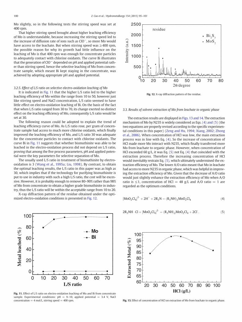
Fig. 9. Effect of NaCl concentration on electro-oxidation leaching of Mo and Bi from con-centrate sample. Experimental conditions: pH= 9–10, applied potential = 3.4 V, stirringspeed = 300 rpm, L/S ratio = 50.
not sufficient for the leaching of concentrate sample; when voltagewas N4.0 V, part of ClO− was further oxidized into ClO3
− of which theamount would gradually grow with the increase of applied potentialand in the alkaline leachate, the relatively weak oxidation strength ofClO3
− made it difficult for itself to be converted into Cl−, which actedas the circulation medium during oxidation of concentrate sample, byoxidizing concentrate sample, thus contributing to the decline of con-centration of Cl− and the shortage of chlorine oxidants involved in theoxidation of concentrate sample. Hence, the growth of applied potentialcaused the decrease of the leaching efficiency of Mo when applied po-tential N4.0 V. When potential ranged from 2.0 to 3.5 V, the decline ofthe leaching efficiency of Bi could be considered as a result of the selec-tive leaching of Mo by ClO−which gradually became themajor chlorineoxidant with the rise of applied potential.
When applied potential was =3.4 V, the leaching efficiency of Mocould reach 95.8%,meanwhile the percentage of Bi remaining in the res-idue was 99.3%. Hence, in the following studies, applied potential wasset at 3.4 V.
3.2.3. Effect of NaCl concentration on selective electro-oxidation leaching ofMo
As shown in Fig. 9, NaCl concentration had an evident effect on theleaching of Mo but no obvious influence on the leaching of Bi. WhenNaCl concentration was ≤4 mol/L, more Mo entered the leachate withthe growth of NaCl concentration while Bi remained in the residue.The possible reason is that a low NaCl concentration resulted in inade-quate Cl− in the electrolyte, so the chlorine oxidants which made con-tribution to oxidizing the concentrate sample were not sufficienteither. Based on curve Bi, NaCl concentration appeared to be irrelevantto the leaching of Bi, suggesting that the appropriate pH and applied po-tential determined after the implementation of previous electro-oxidation leaching experiments were able to convert the majority ofCl− into ClO− in the slurry electrolysis process, so it achieved a remark-able selective separation of Mo from concentrate sample.
According to the fact that when NaCl concentration was N4 mol/L,the growth of NaCl concentration hardly affected the leaching of Mo,therefore it would be set at 4 mol/L in the following studies.
3.2.4. Effect of stirring speed on selective electro-oxidation leaching of MoThe results displayed in Fig. 10 show that the rise of stirring speed
resulted in the increase of the leaching efficiency of Mo and seemed ir-relevant to the leaching of Bi, and when stirring speed was ≥400 rpm,the increase of stirring speed just impacted the leaching efficiency of
200 250 300 350 400 450 5000
20
40
60
80
100
Met
al le
ache
d (%
)
Stirring speed (rpm)
Mo Bi
Fig. 10. Effect of stirring speed on electro-oxidation leaching of Mo and Bi from concen-trate sample. Experimental conditions: pH = 9–10, applied potential = 3.4 V, NaClconcentration = 4 mol/L, L/S ratio = 50.
500
1000
1500
2000
2500
♦ Bi2S
3
• MoS2
•
♦
♦
♦♦
Inte
nsity
(a.
u.)
•
♦
residue
100 Z. Cao et al. / Hydrometallurgy 154 (2015) 95–101
Mo slightly, so in the following tests the stirring speed was set at400 rpm.
That higher stirring speed brought about higher leaching efficiencyof Mo is understandable, because increasing the stirring speed led tothe increase of diffusion rate of ions such as ClO−, so more Mo wouldhave access to the leachate. But when stirring speed was ≥400 rpm,the possible reason for why its growth had little influence on theleaching of Mo is that 400 rpm was enough for concentrate particlesto adequately contact with chlorine oxidants. The curve Bi illustratesthat the generation of ClO− depended on pH and applied potential rath-er than stirring speed, hence the selective leaching of Mo from concen-trate sample, which meant Bi kept staying in the concentrate, wasachieved by adopting appropriate pH and applied potential.
10 20 30 40 50 60 70 800
2θ/degree
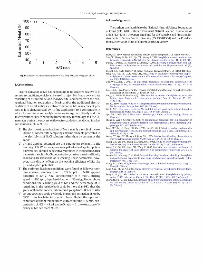
Fig. 12. X-ray diffraction pattern of the residue.
3.2.5. Effect of L/S ratio on selective electro-oxidation leaching of MoIt is indicated in Fig. 11 that the higher L/S ratio led to the higher
leaching efficiency of Mo within the range from 10 to 50, however justlike stirring speed and NaCl concentration, L/S ratio seemed to havelittle effect on electro-oxidation leaching of Bi. On the basis of the factthat when L/S ratio ranged from 30 to 70, its change exerted no distincteffect on the leaching efficiency of Mo, consequently L/S ratio would beset at 30.
The following reason could be adopted to explain the trend ofleaching efficiency curve of Mo. As L/S ratio rose, per gram of concen-trate sample had access to much more chlorine oxidants, which finallyimproved the leaching efficiency of Mo, and L/S ratio 30 was adequatefor the concentrate particles to contact with chlorine oxidants. Thecurve Bi in Fig. 11 suggests that whether bismuthinite was able to beleached in the electro-oxidation process did not depend on L/S ratio,proving that among the five process parameters, pH and applied poten-tial were the key parameters for selective separation of Mo.
The usually used L/S ratio in treatment of bismuthinite by electro-oxidation is 3 (Wang et al., 1995a; Liu, 1998). By contrast, to obtainthe optimal leaching results, the L/S ratio in this paper was as high as30, which implies that if the technology for purifying bismuthinite isput to use in industry with such a high L/S ratio, the cost will be exces-sive. However, it is probably enough to remove 80–90% rather than 98%of Mo from concentrate to obtain a higher grade bismuthinite in indus-try, thus the L/S ratio will be within the acceptable range from 10 to 20.
X-ray diffraction pattern of the residue obtained under the opti-mized electro-oxidation conditions is presented in Fig. 12.
0 10 20 30 40 50 60 700
20
40
60
80
100
Met
al le
ache
d (%
)
L/S ratio
Mo Bi
Fig. 11. Effect of L/S ratio on electro-oxidation leaching of Mo and Bi from concentratesample. Experimental conditions: pH = 9–10, applied potential = 3.4 V, NaClconcentration = 4 mol/L, stirring speed = 400 rpm.
3.3. Results of solvent extraction of Mo from leachate to organic phase
The extraction results are displayed in Figs. 13 and 14. The extractionmechanism ofMo by N235 is widely considered as Eqs. (4) and (5) (thetwo equations are properly revised according to the specific experimen-tal conditions in this paper) (Zeng and Hu, 1994; Xiang, 2002; Zhonget al., 2006). When concentration of HCl was low, the main extractionprocess was in line with Eq. (4). So the increase of concentration ofHCl made more Mo interact with N235, which finally transferred moreMo from leachate to organic phase. However, when concentration ofHCl exceeded 60 g/L, it was Eq. (5) not Eq. (4) that coincided with theextraction process. Therefore the increasing concentration of HClwould inevitably restrain Eq. (5), which ultimately undermined the ex-traction efficiency of Mo. The lower A/O ratiomeant thatMo in leachatehad access tomoreN235 in organic phase, whichwas helpful in improv-ing the extraction efficiency of Mo. Given that the decrease of A/O ratiowould just slightly enhance the extraction efficiency of Mo when A/Oratio is ≤1, concentration of HCl = 48 g/L and A/O ratio = 1 areregarded as the optimum conditions.
MoO2Cl4½ �2‐ þ 2Hþ þ 2R3N ¼ R3NHð Þ2MoO2Cl4 ð4Þ
2R3NH � Clþ MoO2Cl4½ �2‐ ¼ R3NHð Þ2MoO2Cl4 þ 2Cl‐: ð5Þ
20 30 40 50 60 70 80 90 1006065707580859095
100
Ext
ract
ed M
etal
(%
)
HCl (g/L)
Fig. 13. Effect of concentration of HCl on extraction of Mo from leachate to organic phase.
0 1 2 3 4 540
50
60
70
80
90
100E
xtra
cted
Met
al (
%)
A/O ratio
Fig. 14. Effect of A/O ratio on extraction of Mo from leachate to organic phase.
101Z. Cao et al. / Hydrometallurgy 154 (2015) 95–101
4. Conclusions
Electro-oxidation of Mo has been found to be selective relative to Biin certain conditions, which can be used to rejectMo from a concentrateconsisting of bismuthinite and molybdenite. Compared with the con-ventional flotation separation of Mo/Bi and/or the traditional electro-oxidation of metal sulfides, electro-oxidation of Mo is an efficient pro-cess as it is characterized by its fine application to a concentrate inwhich bismuthinite and molybdenite are intergrown closely and it isan environmentally friendly hydrometallurgy technology as little Cl2generates during the process with electro-oxidation conducted in alka-line solutions (pH = 9–10).
(1) The electro-oxidation leaching of Mo is mainly a result of the ox-idation of concentrate sample by chlorine oxidants generated inthe electrolysis of NaCl solution rather than by current at theanode.
(2) pH and applied potential are the parameters relevant to theleaching of Bi. When an appropriate pH value and applied poten-tial were set, Bi could be selectively retained in the residue. Otherparameters such asNaCl concentration, stirring speed and liquid/solid ratio are irrelevant for Bi leaching. These parameters, how-ever, have distinct effects on the leaching efficiency of Mo, likepH and applied potential.
(3) The optimum leaching conditions were found as follows: roomtemperature, leaching time = 2.5 h, pH = 9–10, appliedpotential = 3.4 V, NaCl concentration = 4 mol/L, stirringspeed = 400 rpm, liquid/solid ratio = 30 mL/g. Under aboveconditions, the leaching yield of Mo and the percentage of Biremaining in the residue both could be more than 98%, thus thegrade of Bi in the concentration could go up from 38.12% to 48%.
(4) pH and A/O ratio could evidently impact the extraction of Mo byN235 from leachate to organic phase. Under the optimumconditions of room temperature, extraction time = 5 min, con-centration of HCl = 48 g/L and A/O ratio= 1, the extraction effi-ciency of Mo can reach 99.6%.
Acknowledgments
The authors are thankful to the National Natural Science Foundationof China (21106188), Hunan Provincial Natural Science Foundation ofChina (12JJ4013), the Open-End Fund for the Valuable and Precision In-struments of Central South University (CSUZC201504) and the Postdoc-toral Sustentation Fund of Central South University.
References
Brace, E.C., 1969. Method for treating metallic sulfide compounds. US Patent 3464904.Cao, Z.F., Zhong, H., Liu, G.Y., Qiu, Y.R., Wang, S., 2010. Molybdenum extraction from mo-
lybdenite concentrate in NaCl electrolyte. J. Taiwan Inst. Chem. Eng. 41 (3), 338–343.Darjaa, T., Okabe, T.H., Waseda, Y., Umetsu, Y., 2000. Recovery of molybdenum from sul-
fide concentrate by electro-oxidation and precipitation. Shigen-to-Sozai 116 (3),203–210.
Everett, P.K., 1978. Recovery of copper from ores and concentrates. US Patent 4107009.Feng, A.S., Yue, T.B., Lv, L., Fang, L.H., 2010. Study on separation technology for copper–
molybdenum collective concentrate. XXV International Mineral Processing Congress,pp. 1863–1868 (Brisbane).
Guo, W.G., Zhou, J., 2009. The experiment research of flotation Mo, Bi minerals fromYaogangxian Mo, Bi complex mine. Hunan Nonferrous Met. 25 (5), 15–18 (InChinese).
Kruesi, P.R., 1972. Process for the recovery of metals from sulfide ores through electrolyticdissociation of the sulfides. US Patent 3673061.
Lee, J.J.H., Zeitlin, H., Fernando, Q., 1980. Selective separation of molybdenum as volatilehalides from deep-sea ferromanganese modules. Sep. Sci. Technol. 15 (10),1709–1720.
Liu, Y.J., 1998. Process study on leaching bismuthinite concentrates by slurry electrolysis.Nonferrous Met. Rare earth 4, 8–12 (In Chinese).
Liu, J., 2011. Study on recycling of Mo and Bi from low grade polymetallic deposit inHuangshaping. Mater. Res. Appl. 5 (2), 140–144 (In Chinese).
Qiu, D.F., 1999. Slurry Electrolysis. Metallurgical Industry Press, Beijing, China (InChinese).
Shang, Y., Wang, Z., Cheng, X., 2010. An application of depressant bk510 in separation ofmolybdenite and bismuth by flotation. XXV International Mineral Processing Con-gress, pp. 2351–2355 (Brisbane).
Tang, M.T., Lu, J.Z., Tang, C.B., Chen, Y.M., Jin, S.Y., 2011. Selective leaching sodium saltsand molybdenum from alkaline bismuth smelting slag. J. Cent. South Univ. (Sci.Technol.) 42 (7), 47–51.
Wang, C.Y., Qiu, D.F., Zhang, Y.S., Jiang, P.H., 1995a.Mechanism of leaching bismuthinite inslurry electrowinning process. Nonferrous Met. 47 (2), 54–59 (In Chinese).
Wang, C.Y., Qiu, D.F., Zhang, Y.S., Jiang, P.H., 1995b. Study on slurry electrowinning pro-cess for leaching bismuthinite. Nonferrous Met. 47 (3), 55–60 (In Chinese).
Wang, C.Y., Qiu, D.F., Jiang, P.H., Wang, F., 2002. Formation and oxidation mechanism ofsulfur in the process of slurry electrolysis on bismuthinite. Nonferrous Met. 6, 2–6(In Chinese).
Warren, I.H., Mounsey, D.M., 1983. Factors influencing the selective leaching of molybde-numwith sodium hypochlorite from copper/molybdenum sulphide minerals. Hydro-metallurgy 10 (3), 343–357.
Xiang, T.G., 2002. Molybdenum Metallurgy. Central South University Press, Changsha,China (In Chinese).
Yang, X.W., Zhang, Y.J., 2000. Slurry Electrolysis Principle. Metallurgical Industry Press,Beijing China (In Chinese).
Zeng, P., Hu, J.Y., 1994. Studies on the extraction mechanism of molybdenum by primaryamine N1923 in kerosene. Chem. J. Chin. Univ. 15 (11), 1588–1591 (In Chinese).
Zhong, H., Fu, J.G., Liu, L.B., 2006. Recovery of mo from acid leaching solution containingMo and Mn by solvent extraction of N235. Chin. J. Process Eng. 6 (1), 28–31(In Chinese).