purefire instmanual rev2 - radiant heatradiantheatproducts.com/purefire manual revision 2.pdf ·...
TRANSCRIPT
PUREFIRE® REV2
BoilersPF-50 PF-80 PF-110 PF-140 PF-210 PF-399
Gas
Installation,Operation &MaintenanceManual
As an ENERGY STAR® Partner, PB Heat, LLC has determined that this product meets the ENERGY STAR guidelines for energy efficiency.
®
USING THIS MANUAL 1A. INSTALLATION SEQUENCE . . . . . . . . . . . . . .1B. SPECIAL ATTENTION BOXES . . . . . . . . . . . . .1
1. PREINSTALLATION 2A. GENERAL . . . . . . . . . . . . . . . . . . . . . . . . . . . . .2B. CODES & REGULATIONS . . . . . . . . . . . . . . . .2C. ACCESSIBILITY CLEARANCES . . . . . . . . . . . .3D. COMBUSTION & VENTILATION AIR . . . . . . . .4E. PLANNING THE LAYOUT . . . . . . . . . . . . . . . .6
2. BOILER SET-UP 8A. GENERAL . . . . . . . . . . . . . . . . . . . . . . . . . . . . .8B. WALL MOUNTING . . . . . . . . . . . . . . . . . . . . . .8C. FLOOR STANDING INSTALLATION . . . . . . . . .8
3. VENTING & AIR INLET PIPING 9A. GENERAL . . . . . . . . . . . . . . . . . . . . . . . . . . . . .9B. APPROVED MATERIALS . . . . . . . . . . . . . . . . .9C. EXHAUST VENT/AIR INTAKE
PIPE LOCATION . . . . . . . . . . . . . . . . . . . . . . . .9D. EXHAUST VENT/AIR INTAKE PIPE SIZING . .13E. EXHAUST VENT/AIR INTAKE PIPE
INSTALLATION . . . . . . . . . . . . . . . . . . . . . . . .13F. EXHAUST TAPPING FOR VENT SAMPLE . .14G. BOILER REMOVAL FROM COMMON
VENTING SYSTEM . . . . . . . . . . . . . . . . . . . .14
4. WATER PIPING AND CONTROLS 15A. GENERAL . . . . . . . . . . . . . . . . . . . . . . . . . . . .15B. OPERATING PARAMETERS . . . . . . . . . . . . . .15C. SYSTEM COMPONENTS . . . . . . . . . . . . . . . .15D. SYSTEM PIPING . . . . . . . . . . . . . . . . . . . . . .19E. FREEZE PROTECTION . . . . . . . . . . . . . . . . . .19F. SPECIAL APPLICATIONS . . . . . . . . . . . . . . . .25
5. FUEL PIPING 26A. GENERAL . . . . . . . . . . . . . . . . . . . . . . . . . . . .26B. FUEL LINE SIZING . . . . . . . . . . . . . . . . . . . . .26C. GAS SUPPLY PIPING – INSTALLATION . . . .26D. GAS SUPPLY PIPING – OPERATION . . . . . . .27E. MAIN GAS VALVE – OPERATION . . . . . . . . .28
6. CONDENSATE DRAIN PIPING 29A. GENERAL . . . . . . . . . . . . . . . . . . . . . . . . . . . .29B. CONDENSATE SYSTEM . . . . . . . . . . . . . . . .29C. CONDENSATE DRAIN PIPE MATERIAL . . . .30D. CONDENSATE DRAIN PIPE SIZING . . . . . . .30E. CONDENSATE DRAIN PIPE
INSTALLATION . . . . . . . . . . . . . . . . . . . . . . . .30
7. ELECTRICAL CONNECTIONS 31A. GENERAL . . . . . . . . . . . . . . . . . . . . . . . . . . .31B. CUSTOMER CONNECTIONS . . . . . . . . . . . . .31C. ZONE CIRCULATOR WIRING . . . . . . . . . . . . .32D. INTERNAL WIRING . . . . . . . . . . . . . . . . . . . .32
8. BOILER CONTROL: INTERNALWIRING & OPERATION 36
A. CONTROL OVERVIEW . . . . . . . . . . . . . . . . . .36B. IGNITION SEQUENCE . . . . . . . . . . . . . . . . . .38C. BOILER CONTROL . . . . . . . . . . . . . . . . . . . . .40D. CENTRAL HEATING . . . . . . . . . . . . . . . . . . . .42E. DOMESTIC HOT WATER (DHW) . . . . . . . . . .45F. SERVICE NOTIFICATION . . . . . . . . . . . . . . . .46G. SYSTEM TEST . . . . . . . . . . . . . . . . . . . . . . . .47H. STATUS & FAULT HISTORY . . . . . . . . . . . . . .47I. SENSOR RESISTANCE . . . . . . . . . . . . . . . . .48J. MULTIPLE BOILERS . . . . . . . . . . . . . . . . . . . .48K. DEFAULTS . . . . . . . . . . . . . . . . . . . . . . . . . . .53
9. START-UP PROCEDURE 54A. GENERAL . . . . . . . . . . . . . . . . . . . . . . . . . . . .54B. CHECK WATER PIPING . . . . . . . . . . . . . . . . .54C. CHECK GAS PIPING . . . . . . . . . . . . . . . . . . . .54D. CHECK OPERATION . . . . . . . . . . . . . . . . . . . .54E. LIGHTING & OPERATING PROCEDURES . . .56
10. TROUBLESHOOTING 57A. BLOCKING ERRORS . . . . . . . . . . . . . . . . . . . .57B. LOCKING ERRORS . . . . . . . . . . . . . . . . . . . . .57C. WARNING ERRORS . . . . . . . . . . . . . . . . . . . .61
11. MAINTENANCE 63A. GENERAL (WITH BOILER IN USE) . . . . . . . .64B. WEEKLY (WITH BOILER IN USE) . . . . . . . . .64C. ANNUALLY (BEFORE START OF HEATING
SEASON) . . . . . . . . . . . . . . . . . . . . . . . . . . . .64D. CONDENSATE CLEANING
INSTRUCTIONS . . . . . . . . . . . . . . . . . . . . . . .64E. COMBUSTION CHAMBER COIL CLEANING
INSTRUCTIONS . . . . . . . . . . . . . . . . . . . . . . .65
12. BOILER DIMENSIONS & RATINGS 66
13. REPAIR PARTS 68
APPENDIX A. STATUS SCREENS 76
APPENDIX B. USER MENU 80
APPENDIX C. INSTALLER MENU 81
APPENDIX D. COMBUSTION TESTRECORD 85
TABLE OF CONTENTS
TABLE OF CONTENTS
A. INSTALLATION SEQUENCE
Follow the installation instructions provided in this manualin the order shown. The order of these instructions hasbeen set in order to provide the installer with a logicalsequence of steps that will minimize potentialinterferences and maximize safety during boilerinstallation.
B. SPECIAL ATTENTION BOXES
Throughout this manual special attention boxes areprovided to supplement the instructions and make specialnotice of potential hazards. The definition of each ofthese categories, in the judgement of PB Heat, LLC are as follows:
USING THIS MANUAL
Indicates special attention is needed, but not directlyrelated to potential personal injury or propertydamage.
NOTICE
Indicates a condition or hazard which will or cancause minor personal injury or property damage.
CAUTION
DANGERIndicates a condition or hazard which will causesevere personal injury, death or major propertydamage.
Indicates a condition or hazard which may causesevere personal injury, death or major propertydamage.
WARNING
1
USING THIS MANUAL
A. GENERAL
1. PUREFIRE® boilers are supplied completely assembledas packaged boilers. The package should be inspectedfor damage upon receipt and any damage to the unitshould be reported to the shipping company andwholesaler. This boiler should be stored in a clean, dryarea.
2. Carefully read these instructions and be sure tounderstand the function of all connections prior tobeginning installation. Contact your PB Heat, LLCRepresentative for help in answering questions.
3. This boiler must be installed by a qualified contractor.The boiler warranty may be voided if the boiler is notinstalled correctly.
4. A hot water boiler installed above radiation or asrequired by the Authority having jurisdiction, must beprovided with a low water fuel cut-off device either aspart of the boiler or at the time of installation.
B. CODES & REGULATIONS
1. Installation and repairs are to be performed in strictaccordance with the requirements of state and localregulating agencies and codes dealing with boiler andgas appliance installation.
2. In the absence of local requirements the followingshould be followed:a. ASME Boiler and Pressure Vessel Code, Section
IV - “Heating Boilers”
b. ASME Boiler and Pressure Vessel Code, SectionVI - “Recommended Rules for the Care andOperation of Heating Boilers”
c. ANSI Z223.1/NFPA 54 - “National Fuel Gas Code”
d. ANSI/NFPA 70 - “National Electrical Code”
e. ANSI/NFPA 211 - “Chimneys, Fireplaces, Ventsand Solid Fuel Burning Appliances”
3. Where required by the authority having jurisdiction,the installation must conform to the Standard forControls and Safety Devices for Automatically FiredBoilers, ANSI/ASME CSD-1.
**Please read if installing in Massachusetts**Massachusetts requires manufacturers of Side WallVented boilers to provide the following informationfrom the Massachusetts code:
· A hard wired carbon monoxide detector with analarm and battery back-up must be installed onthe floor level where the gas equipment is to beinstalled AND on each additional level of thedwelling, building or structure served by the sidewall horizontal vented gas fueled equipment.
· In the event that the side wall horizontally ventedgas fueled equipment is installed in a crawl spaceor an attic, the hard wired carbon monoxidedetector with alarm and battery back-up may beinstalled on the next adjacent floor level.
· Detector(s) must be installed by qualified licensedprofessionals.
· APPROVED CARBON MONOXIDEDETECTORS: Each carbon monoxide detectorshall comply with NFPA 720 and be ANSI/UL2034 listed and IAS certified.
· SIGNAGE: A metal or plastic identification plateshall be permanently mounted to the exterior ofthe building at a minimum height of eight (8) feetabove grade directly in line with the exhaust ventterminal for the horizontally vented gas fueledheating appliance or equipment. The sign shallread, in print size no less than one-half (1/2) inchin size, “GAS VENT DIRECTLY BELOW.KEEP CLEAR OF ALL OBSTRUCTIONS”.
· EXEMPTIONS to the requirements listed above:
° The above requirements do not apply if theexhaust vent termination is seven (7) feet ormore above finished grade in the area of theventing, including but not limited to decks andporches.
° The above requirements do not apply to aboiler installed in a room or structure separatefrom the dwelling, building or structure used inwhole or in part for residential purposes.
· This boiler installation manual shall remain withthe boiler at the completion of the installation.
See the latest edition of Massachusetts Code 248 CMRfor complete verbage and also for additional (non-ventrelated) requirements (248 CMR is available online).
If your installation is NOT in Massachusetts, pleasesee your authority of jurisdiction for requirements thatmay be in effect in your area. In the absence of suchrequirements, follow the National Fuel Gas Code,ANSI Z223.1/NFPA 54 and/or CAN/CSA B149.1,Natural Gas and Propane Installation Code.
2
PREINSTALLATION
1. PREINSTALLATION
Liquefied Petroleum (LP) Gas or Propane is heavierthan air and, in the event of a leak, may collect in lowareas such as basements or floor drains. The gasmay then ignite resulting in a fire or explosion.
WARNING
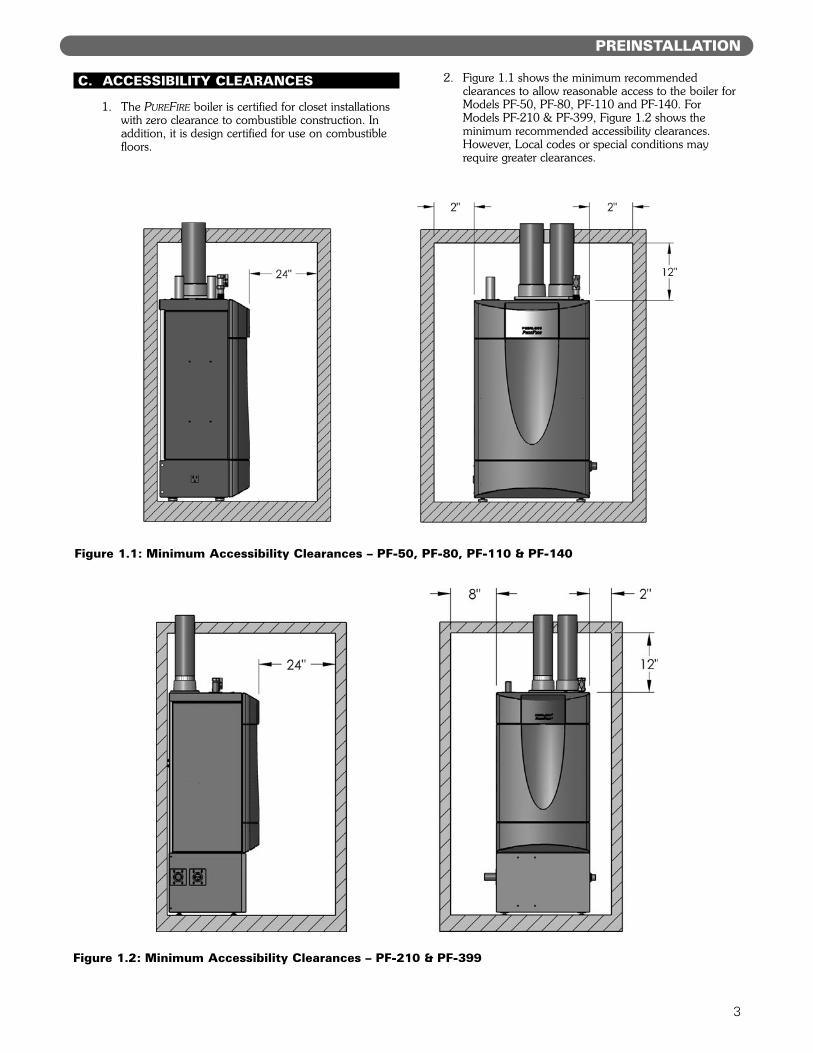
C. ACCESSIBILITY CLEARANCES
1. The PUREFIRE boiler is certified for closet installationswith zero clearance to combustible construction. Inaddition, it is design certified for use on combustiblefloors.
2. Figure 1.1 shows the minimum recommendedclearances to allow reasonable access to the boiler forModels PF-50, PF-80, PF-110 and PF-140. ForModels PF-210 & PF-399, Figure 1.2 shows theminimum recommended accessibility clearances.However, Local codes or special conditions mayrequire greater clearances.E. D.COMBUSTION AND VENTILATION AIR
3
PREINSTALLATION
Figure 1.1: Minimum Accessibility Clearances – PF-50, PF-80, PF-110 & PF-140
Figure 1.2: Minimum Accessibility Clearances – PF-210 & PF-399
D. COMBUSTION AND VENTILATION AIR
1. The PUREFIRE boiler is designed for operation withcombustion air piped directly to the boiler fromoutside the building (sealed combustion). If the boileris vented vertically, the combustion air can besupplied from within the building only if adequatecombustion air and ventilation air is provided inaccordance with the section of the National Fuel GasCode entitled, "Air for Combustion and Ventilation" orapplicable provisions of the local building code.Subsections 3 through 10 as follows are based on theNational Fuel Gas Code requirements.
2. If the combustion air is piped directly to the boilerfrom outside the building, no additional combustionor ventilation air is required. Otherwise, follow theNational Fuel Gas Code recommendationssummarized in subsections 3 through 10.
3. Required Combustion Air Volume: The total requiredvolume of indoor air is to be the sum of the requiredvolumes for all appliances located within the space.Rooms communicating directly with the space inwhich the appliances are installed and throughcombustion air openings sized as indicated inSubsection 3 are considered part of the requiredvolume. The required volume of indoor air is to bedetermined by one of two methods.a. Standard Method: The minimum required volume
of indoor air (room volume) shall be 50 cubic feetper 1000 BTU/Hr (4.8 m3/kW). This method is tobe used if the air infiltration rate is unknown or ifthe rate of air infiltration is known to be greaterthan 0.6 air changes per hour. As an option, thismethod may be used if the air infiltration rate isknown to be between 0.6 and 0.4 air changes perhour. If the air infiltration rate is known to bebelow 0.4 then the Known Air Infiltration RateMethod must be used. If the building in which thisappliance is to be installed is unusually tight, PBHeat recommends that the air infiltration rate bedetermined.
b. Known Air Infiltration Rate Method:
where:Ifan = Input of the fan assisted appliances
assisted in Btu/hrACH = air change per hour (percent of the
volume of the space exchanged perhour, expressed as a decimal)
Note: These calculations are not to be used forinfiltration rates greater than 0.60 ACH.
4. Indoor Air Opening Size and Location: Openingsconnecting indoor spaces shall be sized and located asfollows:
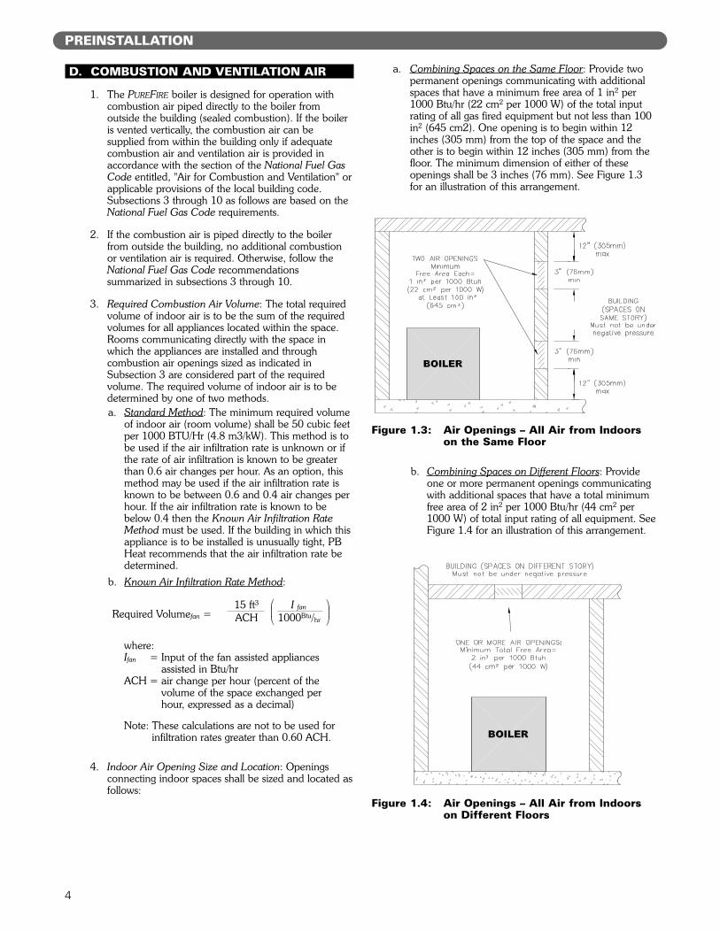
a. Combining Spaces on the Same Floor: Provide twopermanent openings communicating with additionalspaces that have a minimum free area of 1 in2 per1000 Btu/hr (22 cm2 per 1000 W) of the total inputrating of all gas fired equipment but not less than 100in2 (645 cm2). One opening is to begin within 12inches (305 mm) from the top of the space and theother is to begin within 12 inches (305 mm) from thefloor. The minimum dimension of either of theseopenings shall be 3 inches (76 mm). See Figure 1.3for an illustration of this arrangement.
b. Combining Spaces on Different Floors: Provideone or more permanent openings communicatingwith additional spaces that have a total minimumfree area of 2 in2 per 1000 Btu/hr (44 cm2 per1000 W) of total input rating of all equipment. SeeFigure 1.4 for an illustration of this arrangement.
4
15 ft3 I fan
ACH 1000Btu/hrRequired Volumefan =
!"# !
"#
Figure 1.3: Air Openings – All Air from Indoorson the Same Floor
Figure 1.4: Air Openings – All Air from Indoorson Different Floors
PREINSTALLATION
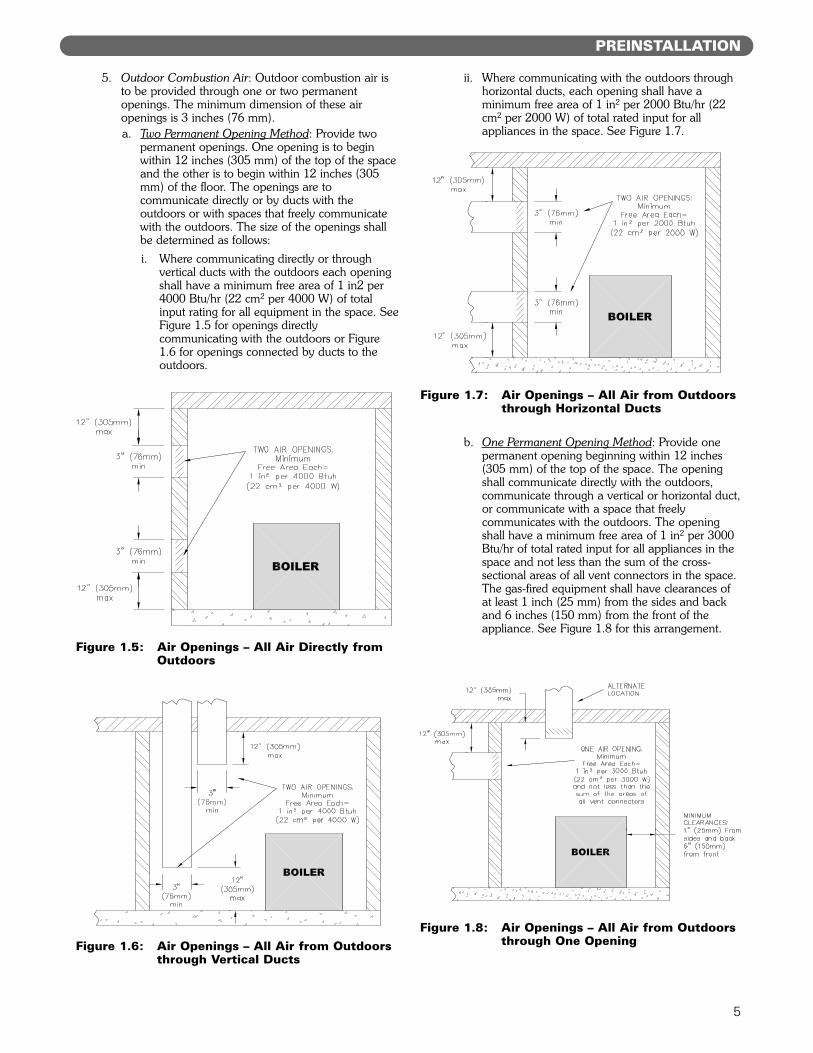
5. Outdoor Combustion Air: Outdoor combustion air isto be provided through one or two permanentopenings. The minimum dimension of these airopenings is 3 inches (76 mm).a. Two Permanent Opening Method: Provide two
permanent openings. One opening is to beginwithin 12 inches (305 mm) of the top of the spaceand the other is to begin within 12 inches (305mm) of the floor. The openings are tocommunicate directly or by ducts with theoutdoors or with spaces that freely communicatewith the outdoors. The size of the openings shallbe determined as follows:i. Where communicating directly or through
vertical ducts with the outdoors each openingshall have a minimum free area of 1 in2 per4000 Btu/hr (22 cm2 per 4000 W) of totalinput rating for all equipment in the space. SeeFigure 1.5 for openings directlycommunicating with the outdoors or Figure1.6 for openings connected by ducts to theoutdoors.
ii. Where communicating with the outdoors throughhorizontal ducts, each opening shall have aminimum free area of 1 in2 per 2000 Btu/hr (22cm2 per 2000 W) of total rated input for allappliances in the space. See Figure 1.7.
b. One Permanent Opening Method: Provide onepermanent opening beginning within 12 inches(305 mm) of the top of the space. The openingshall communicate directly with the outdoors,communicate through a vertical or horizontal duct,or communicate with a space that freelycommunicates with the outdoors. The openingshall have a minimum free area of 1 in2 per 3000Btu/hr of total rated input for all appliances in thespace and not less than the sum of the cross-sectional areas of all vent connectors in the space.The gas-fired equipment shall have clearances ofat least 1 inch (25 mm) from the sides and backand 6 inches (150 mm) from the front of theappliance. See Figure 1.8 for this arrangement.
5
Figure 1.5: Air Openings – All Air Directly fromOutdoors
Figure 1.6: Air Openings – All Air from Outdoorsthrough Vertical Ducts
Figure 1.7: Air Openings – All Air from Outdoorsthrough Horizontal Ducts
Figure 1.8: Air Openings – All Air from Outdoorsthrough One Opening
PREINSTALLATION
6. Combination Indoor and Outdoor Combustion Air: Ifthe required volume of indoor air exceeds theavailable indoor air volume, outdoor air openings orducts may be used to supplement the available indoorair provided:a. The size and location of the indoor openings
comply with Subsection 3.b. The outdoor openings are to be located in
accordance with Subsection 4.c. The size of the outdoor openings are to be sized
as follows:where:Areq = minimum area of outdoor openings.Afull = full size of outdoor openings calculated
in accordance with Subsection 4.Vavail = available indoor air volumeVreq = required indoor air volume
7. Engineered Installations: Engineered combustion airinstallations shall provide an adequate supply ofcombustion, ventilation, and dilution air and shall beapproved by the authority having jurisdiction.
8. Mechanical Combustion Air Supply:a. In installations where all combustion air is
provided by a mechanical air supply system, thecombustion air shall be supplied from theoutdoors at the minimum rate of 0.35 ft3/min per1000 Btu/hr (0.034 m3/min per 1000 W) of thetotal rated input of all appliances in the space.
b. In installations where exhaust fans are installed,additional air shall be provided to replace theexhaust air.
c. Each of the appliances served shall be interlockedto the mechanical air supply to prevent mainburner operation when the mechanical air supplysystem is not in operation.
d. In buildings where the combustion air is providedby the mechanical ventilation system, the systemshall provide the specified combustion air rate inaddition to the required ventilation air.
9. Louvers & Grills:a. The required size of openings for combustion,
ventilation, and dilution air shall be based on thenet free area of each opening.i. Where the free area through a louver or grille
is known, it shall be used in calculating theopening size required to provide the free areaspecified.
ii. Where the free area through a louver or grilleis not known, it shall be assumed that woodenlouvers will have 25% free area and metallouvers and grilles will have 75% free area.
iii. Non-motorized dampers shall be fixed in theopen position.
b. Motorized dampers shall be interlocked with theequipment so that they are proven in the full openposition prior to ignition and during operation ofthe main burner.
i. The interlock shall prevent the main burnerfrom igniting if the damper fails to open duringburner startup.
ii. The interlock shall shut down the burner if thedamper closes during burner operation.
10. Combustion Air Ducts:a. Ducts shall be constructed of galvanized steel or
an equivalent corrosion- resistant material.b. Ducts shall terminate in an unobstructed space,
allowing free movement of combustion air to theappliances.
c. Ducts shall serve a single space.d. Ducts shall not serve both upper and lower
combustion air openings where both suchopenings are used. The separation between ductsserving upper and lower combustion air openingsshall be maintained to the source of combustionair.
e. Ducts shall not be screened where terminating inan attic space.
f. Horizontal upper combustion air ducts shall notslope downward toward the source of thecombustion air.
g. The remaining space surrounding a chimney liner,gas vent, special gas vent, or plastic pipinginstalled within a masonry, metal, or factory builtchimney shall not be used to supply combustionair unless it is directly piped to the air inlet asshown in Figure 3.9.
h. Combustion air intake openings located on theexterior of buildings shall have the lowest side ofthe combustion air intake opening at least 12inches (305 mm) above grade.
11. Refer to Section 3 of this manual, Venting & Air InletPiping, for specific instructions for piping the exhaustand combustion air.
E. PLANNING THE LAYOUT
1. Prepare sketches and notes showing the layout of theboiler installation to minimize the possibility ofinterferences with new or existing equipment, piping,venting and wiring.
2. The following sections of this manual should bereviewed for consideration of limitations with respect to:a. Venting and Air Inlet Piping: Section 3b. Water Piping: Section 4c. Fuel Piping: Section 5d. Condensate Removal: Section 6e. Electrical Connections: Section 7f. Boiler Control: Section 8g. Boiler Dimensions and Ratings: Section 12
6
PREINSTALLATION
7
Do not install this boiler where gasoline or otherflammable liquids or vapors are stored or are in use.
WARNING
This boiler is certified as an indoor appliance. Do notinstall this boiler outdoors or locate where it will beexposed to freezing temperatures.
WARNING
Do not install this boiler in the attic.
WARNING
PREINSTALLATION
8
A. GENERAL
1. PUREFIRE boilers are intended for installation in anarea with a floor drain or in a suitable drain pan. Donot install any boiler where leaks or relief valvedischarge will cause property damage.
2. The PUREFIRE boiler is not intended to supportexternal piping. All venting and other piping shouldbe supported independently of the boiler.
3. Install the boiler level to prevent condensate frombacking up inside the boiler.
4. PUREFIRE boilers can be wall mounted or floorstanding. The following instructions provide guidancefor both configurations.
B. WALL MOUNTING
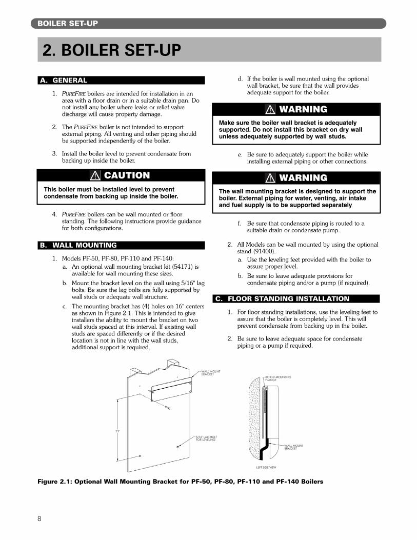
1. Models PF-50, PF-80, PF-110 and PF-140:a. An optional wall mounting bracket kit (54171) is
available for wall mounting these sizes.b. Mount the bracket level on the wall using 5/16" lag
bolts. Be sure the lag bolts are fully supported bywall studs or adequate wall structure.
c. The mounting bracket has (4) holes on 16" centersas shown in Figure 2.1. This is intended to giveinstallers the ability to mount the bracket on twowall studs spaced at this interval. If existing wallstuds are spaced differently or if the desiredlocation is not in line with the wall studs,additional support is required.
d. If the boiler is wall mounted using the optionalwall bracket, be sure that the wall providesadequate support for the boiler.
e. Be sure to adequately support the boiler whileinstalling external piping or other connections.
f. Be sure that condensate piping is routed to asuitable drain or condensate pump.
2. All Models can be wall mounted by using the optionalstand (91400).a. Use the leveling feet provided with the boiler to
assure proper level.b. Be sure to leave adequate provisions for
condensate piping and/or a pump (if required).
C. FLOOR STANDING INSTALLATION
1. For floor standing installations, use the leveling feet toassure that the boiler is completely level. This willprevent condensate from backing up in the boiler.
2. Be sure to leave adequate space for condensatepiping or a pump if required.
BOILER SET-UP
2. BOILER SET-UP
The wall mounting bracket is designed to support theboiler. External piping for water, venting, air intakeand fuel supply is to be supported separately
WARNING
Figure 2.1: Optional Wall Mounting Bracket for PF-50, PF-80, PF-110 and PF-140 Boilers
This boiler must be installed level to preventcondensate from backing up inside the boiler.
CAUTION
Make sure the boiler wall bracket is adequatelysupported. Do not install this bracket on dry wallunless adequately supported by wall studs.
WARNING
9
A. GENERAL
1. Install the PUREFIRE boiler venting system in accordancewith these instructions and with the National Fuel GasCode, ANSI Z223.1/NFPA 54, CAN/CGA B149, and/orapplicable provisions of local building codes.
2. The PUREFIRE boiler is a direct vent appliance and isETL Listed as a Category IV appliance with IntertekTesting Laboratories, Inc.
B. APPROVED MATERIALS
1. Table 3.1 lists approved materials for vent pipe (andadhesives where applicable). Use only these materialsfor exhaust vent piping.
2. PVC pipe and fittings are not to be used for venting inconfined spaces such as closet installations. Use onlyCPVC or Mugro™ vent pipe under these conditions.
3. Cellular core piping is approved for inlet air piping only.
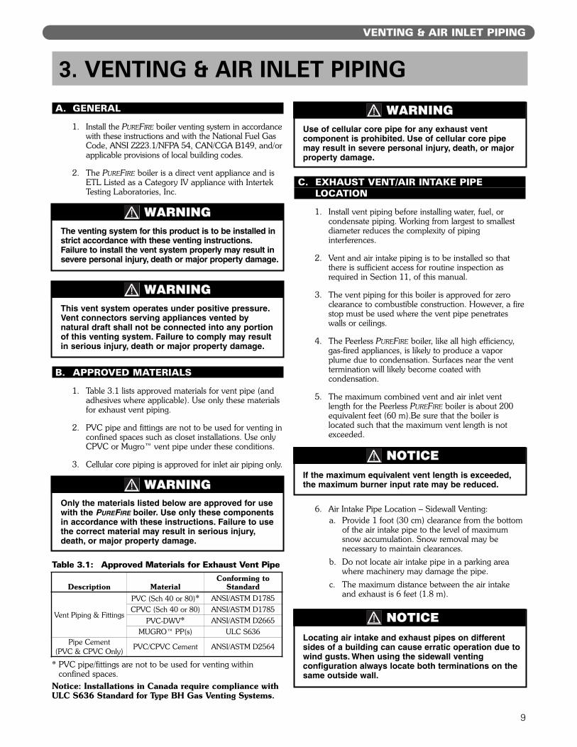
* PVC pipe/fittings are not to be used for venting withinconfined spaces.
Notice: Installations in Canada require compliance withULC S636 Standard for Type BH Gas Venting Systems.
C. EXHAUST VENT/AIR INTAKE PIPELOCATION
1. Install vent piping before installing water, fuel, orcondensate piping. Working from largest to smallestdiameter reduces the complexity of pipinginterferences.
2. Vent and air intake piping is to be installed so thatthere is sufficient access for routine inspection asrequired in Section 11, of this manual.
3. The vent piping for this boiler is approved for zeroclearance to combustible construction. However, a firestop must be used where the vent pipe penetrateswalls or ceilings.
4. The Peerless PUREFIRE boiler, like all high efficiency,gas-fired appliances, is likely to produce a vaporplume due to condensation. Surfaces near the venttermination will likely become coated withcondensation.
5. The maximum combined vent and air inlet ventlength for the Peerless PUREFIRE boiler is about 200equivalent feet (60 m).Be sure that the boiler islocated such that the maximum vent length is notexceeded.
6. Air Intake Pipe Location – Sidewall Venting:a. Provide 1 foot (30 cm) clearance from the bottom
of the air intake pipe to the level of maximumsnow accumulation. Snow removal may benecessary to maintain clearances.
b. Do not locate air intake pipe in a parking areawhere machinery may damage the pipe.
c. The maximum distance between the air intakeand exhaust is 6 feet (1.8 m).
VENTING & AIR INLET PIPING
3. VENTING & AIR INLET PIPING
The venting system for this product is to be installed instrict accordance with these venting instructions.Failure to install the vent system properly may result insevere personal injury, death or major property damage.
WARNING
This vent system operates under positive pressure.Vent connectors serving appliances vented bynatural draft shall not be connected into any portionof this venting system. Failure to comply may resultin serious injury, death or major property damage.
WARNING
Only the materials listed below are approved for usewith the PUREFIRE boiler. Use only these componentsin accordance with these instructions. Failure to usethe correct material may result in serious injury,death, or major property damage.
WARNING
Table 3.1: Approved Materials for Exhaust Vent Pipe
Use of cellular core pipe for any exhaust ventcomponent is prohibited. Use of cellular core pipemay result in severe personal injury, death, or majorproperty damage.
WARNING
If the maximum equivalent vent length is exceeded,the maximum burner input rate may be reduced.
NOTICE
Locating air intake and exhaust pipes on differentsides of a building can cause erratic operation due towind gusts. When using the sidewall ventingconfiguration always locate both terminations on thesame outside wall.
NOTICE
Description MaterialConforming to
Standard
Vent Piping & Fittings
PVC (Sch 40 or 80)* ANSI/ASTM D1785CPVC (Sch 40 or 80) ANSI/ASTM D1785
PVC-DWV* ANSI/ASTM D2665MUGRO™ PP(s) ULC S636
Pipe Cement(PVC & CPVC Only) PVC/CPVC Cement ANSI/ASTM D2564
d. If the vent pipe and air inlet pipe terminationspenetrate the wall at the same level the minimumdistance between them is 8" center-to-center.
e. For multiple boiler installations, the minimumhorizontal distance between the inlet of one boilerto the exhaust of an adjacent boiler is 8" center-to-center. In addition, the minimum vertical distancebetween the exhaust and air inlet is 6". See Figure3.1 for an illustration.
f. The exhaust outlet of the vent pipe should not beangled any more than 5º from horizontal.
g. Precautions should be taken to preventrecirculation of flue gases to the air inlet pipe ofthe boiler or other adjacent appliances.
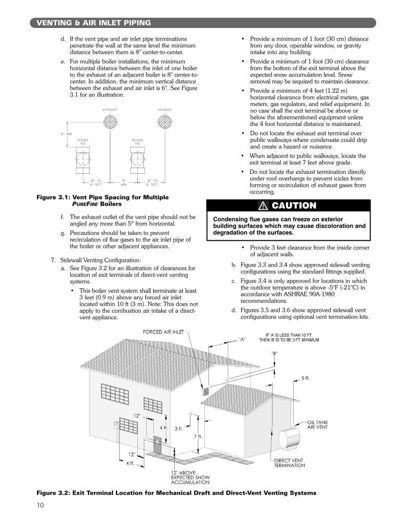
7. Sidewall Venting Configuration:a. See Figure 3.2 for an illustration of clearances for
location of exit terminals of direct-vent ventingsystems.• This boiler vent system shall terminate at least
3 feet (0.9 m) above any forced air inletlocated within 10 ft (3 m). Note: This does notapply to the combustion air intake of a direct-vent appliance.
• Provide a minimum of 1 foot (30 cm) distancefrom any door, operable window, or gravityintake into any building.
• Provide a minimum of 1 foot (30 cm) clearancefrom the bottom of the exit terminal above theexpected snow accumulation level. Snowremoval may be required to maintain clearance.
• Provide a minimum of 4 feet (1.22 m)horizontal clearance from electrical meters, gasmeters, gas regulators, and relief equipment. Inno case shall the exit terminal be above orbelow the aforementioned equipment unlessthe 4 foot horizontal distance is maintained.
• Do not locate the exhaust exit terminal overpublic walkways where condensate could dripand create a hazard or nuisance.
• When adjacent to public walkways, locate theexit terminal at least 7 feet above grade.
• Do not locate the exhaust termination directlyunder roof overhangs to prevent icicles fromforming or recirculation of exhaust gases fromoccurring.
• Provide 3 feet clearance from the inside cornerof adjacent walls.
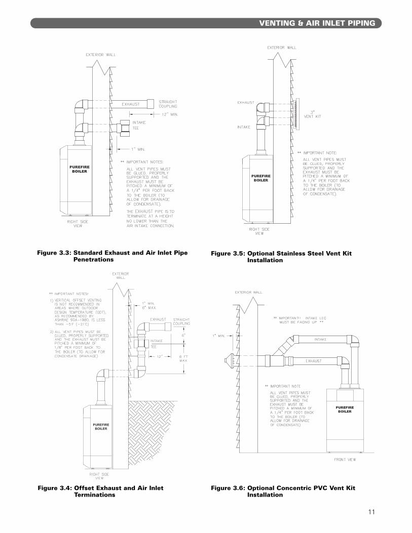
b. Figure 3.3 and 3.4 show approved sidewall ventingconfigurations using the standard fittings supplied.
c. Figure 3.4 is only approved for locations in whichthe outdoor temperature is above -5°F (-21°C) inaccordance with ASHRAE 90A-1980recommendations.
d. Figures 3.5 and 3.6 show approved sidewall ventconfigurations using optional vent termination kits.
10
VENTING & AIR INLET PIPING
Figure 3.1: Vent Pipe Spacing for Multiple PUREFIRE Boilers
Figure 3.2: Exit Terminal Location for Mechanical Draft and Direct-Vent Venting Systems
Condensing flue gases can freeze on exteriorbuilding surfaces which may cause discoloration anddegradation of the surfaces.
CAUTION
11
VENTING & AIR INLET PIPING
Figure 3.3: Standard Exhaust and Air Inlet PipePenetrations
Figure 3.4: Offset Exhaust and Air InletTerminations
Figure 3.5: Optional Stainless Steel Vent KitInstallation
Figure 3.6: Optional Concentric PVC Vent KitInstallation
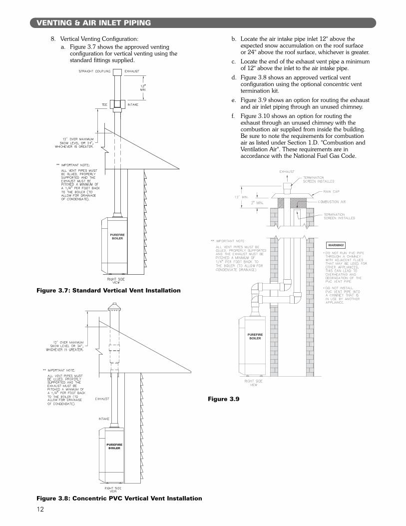
8. Vertical Venting Configuration:a. Figure 3.7 shows the approved venting
configuration for vertical venting using thestandard fittings supplied.
b. Locate the air intake pipe inlet 12" above theexpected snow accumulation on the roof surfaceor 24" above the roof surface, whichever is greater.
c. Locate the end of the exhaust vent pipe a minimumof 12" above the inlet to the air intake pipe.
d. Figure 3.8 shows an approved vertical ventconfiguration using the optional concentric venttermination kit.
e. Figure 3.9 shows an option for routing the exhaustand air inlet piping through an unused chimney.
f. Figure 3.10 shows an option for routing theexhaust through an unused chimney with thecombustion air supplied from inside the building.Be sure to note the requirements for combustionair as listed under Section 1.D. "Combustion andVentilation Air". These requirements are inaccordance with the National Fuel Gas Code.
12
VENTING & AIR INLET PIPING
Figure 3.7: Standard Vertical Vent Installation
Figure 3.8: Concentric PVC Vertical Vent Installation
Figure 3.9

13
D. EXHAUST VENT/AIR INTAKE PIPE SIZING
1. PUREFIRE boiler models PF-50, PF-80, PF-110, PF-140and PF-210 are to be installed using 3" Schedule 40or 80 PVC or CPVC piping using the provided ventadapter. PUREFIRE model PF-399 boilers are to beinstalled using 4" Schedule 40 or 80 PVC or CPVCpiping using the vent adapter provided.
2. Concentric polypropylene venting systems can beinstalled using optional MUGRO™ vent adapters.Table 3.2 shows the appropriate Stock Codes.
Contact your PB Heat, LLC Representative for moreinformation on this option.
3. The total combined length of exhaust vent and airintake piping is 200 equivalent feet (60 m).a. The equivalent length of elbows, tees and other
fittings are listed in Table 3.3.
b. The equivalent length can be calculated as follows.
This is well below the 200 feet maximumequivalent length. If the total is above 200equivalent feet, alternate boiler locations orexhaust penetration location should be considered.
E. EXHAUST VENT/AIR INTAKEINSTALLATION
1. Figures 12.1 & 12.2 show the exhaust connection ontop of the boiler, near the rear in the center.a. The exhaust connection for PF-50, PF-80, PF- 110
and PF-140 boilers is a 3" CPVC Female PipeAdapter.
b. The exhaust connections for the PF-210 (3") andPF-399 (4") are male CPVC pipe.
c. These connections are to be joined with suitablePVC/CPVC adhesives in accordance withmanufacturers’ instructions.
2. The Air Intake connection is to the right of the exhaust.
3. Both connections are clearly marked.
4. Remove all burrs and debris from the joints and fittings.
5. Horizontal lengths of exhaust vent must be installed witha slope of not less than 1/4" per foot (21mm per meter)toward the boiler to allow condensate to drain from thevent pipe. If the vent pipe must be piped around anobstacle that causes a low point in the piping, a drainwith an appropriate trap must be installed.
VENTING & AIR INLET PIPING
This appliance uses a positive pressure ventingsystem. All joints must be sealed completely toprevent leakage of flue products into living spaces.Failure to do this may result in severe personal injury,death or major property damage.
WARNING
Exhaust Air Inlet TotalStraight Length of Pipe 50' 50' 100'
90° Elbows, SR 2 x 5'= 10' 1 x 5' = 5' 15'45° Elbows, SR 2 x 3' = 6' 6'
Conc. Vent Termination 1 x 3' = 3' 3'Total 124'
Table 3.4: Sample Equivalent Length Calculation
Figure 3.10
Boiler Model Stock Code Boiler Model Stock Code
PF-50 54155 PF-140 54155
PF-80 54155 PF-210 54236
PF-110 54155 PF-399 54237
Table 3.2: Stock Codes
Fitting Description Equivalent LengthElbow, 90° Short Radius 5 feetElbow, 90° Long Radius 4 feetElbow, 45° Short Radius 3 feet
Coupling 0 feetAir Intake Tee 0 feet
Stainless Steel Vent Kit 1 footConcentric Vent Kit 3 feet
Table 3.3: Equivalent Length of Fittings
6. All piping must be fully supported. Use pipe hangersat a minimum of 4 foot (1.22 meter) intervals toprevent sagging of the pipe.
7. Exhaust and air inlet piping is to be supportedseparately and should not apply force to the boiler.
8. Penetration openings around the vent pipe and airintake piping are to be fully sealed to prevent exhaustgases from entering building structures.
9. PVC & CPVC Piping:a. Use only solid PVC or CPVC Schedule 40 or 80
pipe for exhaust venting. Cellular core PVC orCPVC is not approved for exhaust vent.
b. All joints in vent pipe, fittings, attachment to theboiler stub, and all vent termination joints must beproperly cleaned, primed and cemented. Use onlycement and primer approved for use with PVC orCPVC pipe that conforms to ANSI/ASTM D2564.
c. A straight coupling is provided with the boiler tobe used as an outside vent termination. One ofthe two screens is to be installed to prevent birdsor rodents from entering.
d. An air intake tee is provided with the boiler to beused as an outside air intake termination. A screenis to be installed to prevent birds or rodents fromentering.
e. The following are optional combination airintake/exhaust terminations that are availableseparately from your PB Heat, LLC distributor foruse with PUREFIRE boilers.
f. Refer to Figures 3.3 to 3.6 for sidewall ventingoptions using PVC or CPVC pipe.
g. Refer to Figures 3.7 & 3.8 for vertical ventingoptions using PVC or CPVC pipe.
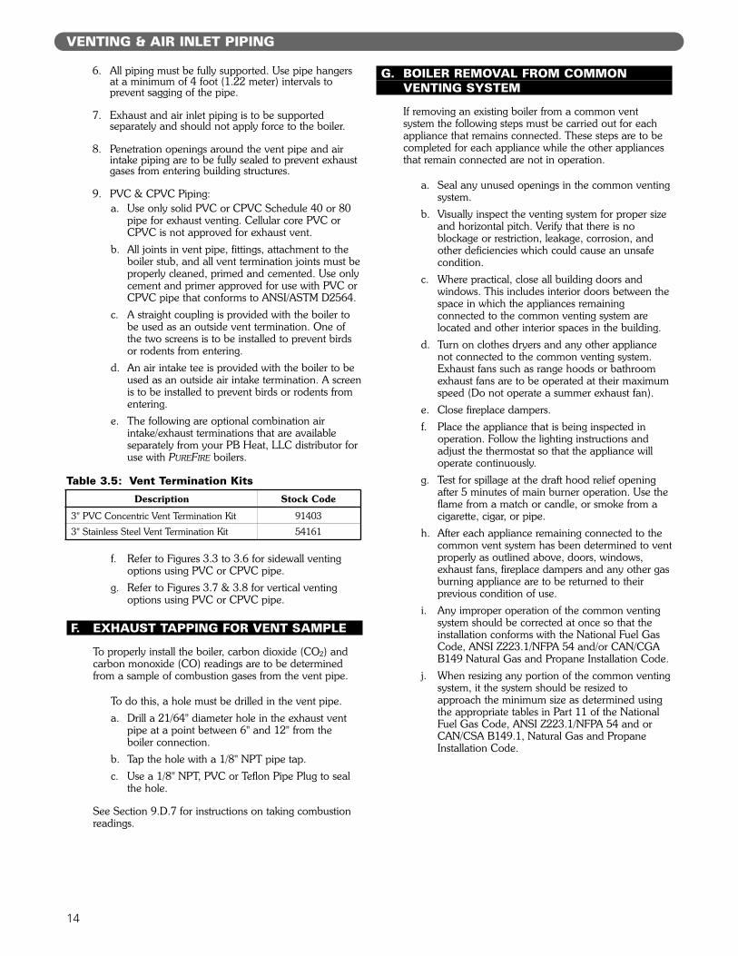
F. EXHAUST TAPPING FOR VENT SAMPLE
To properly install the boiler, carbon dioxide (CO2) andcarbon monoxide (CO) readings are to be determinedfrom a sample of combustion gases from the vent pipe.
To do this, a hole must be drilled in the vent pipe.a. Drill a 21/64" diameter hole in the exhaust vent
pipe at a point between 6" and 12" from the boiler connection.
b. Tap the hole with a 1/8" NPT pipe tap.c. Use a 1/8" NPT, PVC or Teflon Pipe Plug to seal
the hole.
See Section 9.D.7 for instructions on taking combustionreadings.
G. BOILER REMOVAL FROM COMMONVENTING SYSTEM
If removing an existing boiler from a common ventsystem the following steps must be carried out for eachappliance that remains connected. These steps are to becompleted for each appliance while the other appliancesthat remain connected are not in operation.
a. Seal any unused openings in the common ventingsystem.
b. Visually inspect the venting system for proper sizeand horizontal pitch. Verify that there is noblockage or restriction, leakage, corrosion, andother deficiencies which could cause an unsafecondition.
c. Where practical, close all building doors andwindows. This includes interior doors between thespace in which the appliances remainingconnected to the common venting system arelocated and other interior spaces in the building.
d. Turn on clothes dryers and any other appliancenot connected to the common venting system.Exhaust fans such as range hoods or bathroomexhaust fans are to be operated at their maximumspeed (Do not operate a summer exhaust fan).
e. Close fireplace dampers.f. Place the appliance that is being inspected in
operation. Follow the lighting instructions andadjust the thermostat so that the appliance willoperate continuously.
g. Test for spillage at the draft hood relief openingafter 5 minutes of main burner operation. Use theflame from a match or candle, or smoke from acigarette, cigar, or pipe.
h. After each appliance remaining connected to thecommon vent system has been determined to ventproperly as outlined above, doors, windows,exhaust fans, fireplace dampers and any other gasburning appliance are to be returned to theirprevious condition of use.
i. Any improper operation of the common ventingsystem should be corrected at once so that theinstallation conforms with the National Fuel GasCode, ANSI Z223.1/NFPA 54 and/or CAN/CGAB149 Natural Gas and Propane Installation Code.
j. When resizing any portion of the common ventingsystem, it the system should be resized toapproach the minimum size as determined usingthe appropriate tables in Part 11 of the NationalFuel Gas Code, ANSI Z223.1/NFPA 54 and orCAN/CSA B149.1, Natural Gas and PropaneInstallation Code.
14
VENTING & AIR INLET PIPING
Description Stock Code
3" PVC Concentric Vent Termination Kit 91403
3" Stainless Steel Vent Termination Kit 54161
Table 3.5: Vent Termination Kits
15
A. GENERAL
1. Size water supply and return piping in accordancewith system requirements. Do not use smallerdiameter piping than the boiler connections.
2. If the PUREFIRE boiler is used to replace an existingboiler, make sure that the system piping is thoroughlycleaned and free from debris before installing this boiler.
3. In hydronic systems where sediment may exist, installa strainer in the boiler return piping to prevent largeparticles and pipe scale from entering the boiler heatexchanger. Use a large mesh screen in the strainer.
4. Install this boiler so that the gas ignition systemcomponents are protected from water (dripping, spraying,etc.) during operation and service (circulator replacement,condensate trap cleaning, sensor replacement, etc.).
B. OPERATING PARAMETERS
1. The PUREFIRE boiler is designed to operate in a closedloop hydronic system under forced circulation. Thisrequires the system to be completely filled with waterand requires a minimum water flow through the boilerto operate effectively.
2. The minimum system pressure is 14.5 PSI (69 kPa).
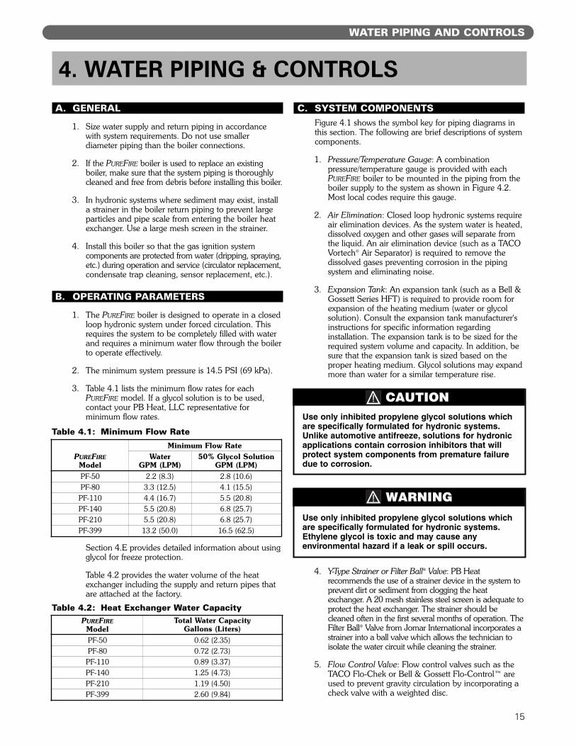
3. Table 4.1 lists the minimum flow rates for eachPUREFIRE model. If a glycol solution is to be used,contact your PB Heat, LLC representative forminimum flow rates.
Section 4.E provides detailed information about usingglycol for freeze protection.
Table 4.2 provides the water volume of the heatexchanger including the supply and return pipes thatare attached at the factory.
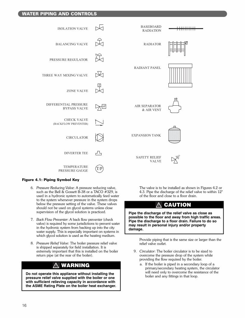
C. SYSTEM COMPONENTSFigure 4.1 shows the symbol key for piping diagrams inthis section. The following are brief descriptions of systemcomponents.
1. Pressure/Temperature Gauge: A combinationpressure/temperature gauge is provided with eachPUREFIRE boiler to be mounted in the piping from theboiler supply to the system as shown in Figure 4.2.Most local codes require this gauge.
2. Air Elimination: Closed loop hydronic systems requireair elimination devices. As the system water is heated,dissolved oxygen and other gases will separate fromthe liquid. An air elimination device (such as a TACOVortech® Air Separator) is required to remove thedissolved gases preventing corrosion in the pipingsystem and eliminating noise.
3. Expansion Tank: An expansion tank (such as a Bell &Gossett Series HFT) is required to provide room forexpansion of the heating medium (water or glycolsolution). Consult the expansion tank manufacturer'sinstructions for specific information regardinginstallation. The expansion tank is to be sized for therequired system volume and capacity. In addition, besure that the expansion tank is sized based on theproper heating medium. Glycol solutions may expandmore than water for a similar temperature rise.
4. Y-Type Strainer or Filter Ball® Valve: PB Heatrecommends the use of a strainer device in the system toprevent dirt or sediment from clogging the heatexchanger. A 20 mesh stainless steel screen is adequate toprotect the heat exchanger. The strainer should becleaned often in the first several months of operation. TheFilter Ball® Valve from Jomar International incorporates astrainer into a ball valve which allows the technician toisolate the water circuit while cleaning the strainer.
5. Flow Control Valve: Flow control valves such as theTACO Flo-Chek or Bell & Gossett Flo-Control™ areused to prevent gravity circulation by incorporating acheck valve with a weighted disc.
WATER PIPING AND CONTROLS
4. WATER PIPING & CONTROLS
Use only inhibited propylene glycol solutions whichare specifically formulated for hydronic systems.Unlike automotive antifreeze, solutions for hydronicapplications contain corrosion inhibitors that willprotect system components from premature failuredue to corrosion.
CAUTION
Use only inhibited propylene glycol solutions whichare specifically formulated for hydronic systems.Ethylene glycol is toxic and may cause anyenvironmental hazard if a leak or spill occurs.
WARNING
PUREFIREModel
Minimum Flow RateWater
GPM (LPM)50% Glycol Solution
GPM (LPM)PF-50 2.2 (8.3) 2.8 (10.6)PF-80 3.3 (12.5) 4.1 (15.5)
PF-110 4.4 (16.7) 5.5 (20.8)PF-140 5.5 (20.8) 6.8 (25.7)PF-210 5.5 (20.8) 6.8 (25.7)PF-399 13.2 (50.0) 16.5 (62.5)
Table 4.1: Minimum Flow Rate
PUREFIREModel
Total Water Capacity Gallons (Liters)
PF-50 0.62 (2.35)PF-80 0.72 (2.73)
PF-110 0.89 (3.37)PF-140 1.25 (4.73)PF-210 1.19 (4.50)PF-399 2.60 (9.84)
Table 4.2: Heat Exchanger Water Capacity
16
6. Pressure Reducing Valve: A pressure reducing valve,such as the Bell & Gossett B-38 or a TACO #329, isused in a hydronic system to automatically feed waterto the system whenever pressure in the system dropsbelow the pressure setting of the valve. These valvesshould not be used on glycol systems unless closesupervision of the glycol solution is practiced.
7. Back Flow Preventer: A back flow preventer (checkvalve) is required by some jurisdictions to prevent waterin the hydronic system from backing up into the citywater supply. This is especially important on systems inwhich glycol solution is used as the heating medium.
8. Pressure Relief Valve: The boiler pressure relief valveis shipped separately for field installation. It isextremely important that this is installed on the boilerreturn pipe (at the rear of the boiler).
The valve is to be installed as shown in Figures 4.2 or4.3. Pipe the discharge of the relief valve to within 12"of the floor and close to a floor drain.
Provide piping that is the same size or larger than therelief valve outlet.
9. Circulator: The boiler circulator is to be sized toovercome the pressure drop of the system whileproviding the flow required by the boiler.a. If the boiler is piped in a secondary loop of a
primary/secondary heating system, the circulatorwill need only to overcome the resistance of theboiler and any fittings in that loop.
WATER PIPING AND CONTROLS
Figure 4.1: Piping Symbol Key
Do not operate this appliance without installing thepressure relief valve supplied with the boiler or onewith sufficient relieving capacity in accordance withthe ASME Rating Plate on the boiler heat exchanger.
WARNING
Pipe the discharge of the relief valve as close aspossible to the floor and away from high traffic areas.Pipe the discharge to a floor drain. Failure to do somay result in personal injury and/or propertydamage.
CAUTION
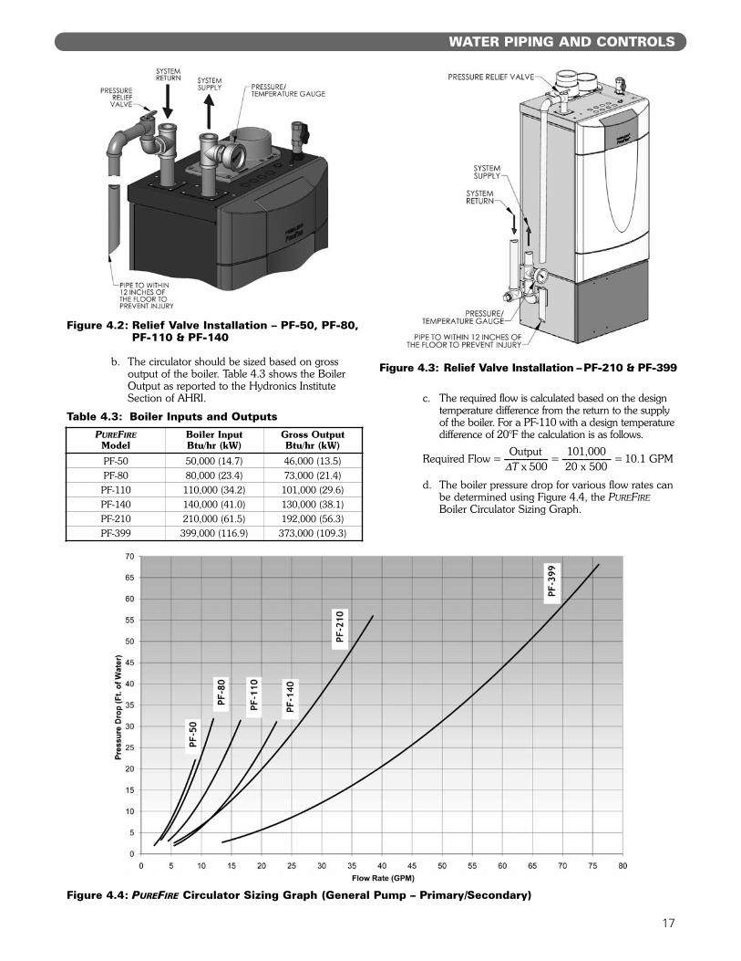
b. The circulator should be sized based on grossoutput of the boiler. Table 4.3 shows the BoilerOutput as reported to the Hydronics InstituteSection of AHRI. c. The required flow is calculated based on the design
temperature difference from the return to the supplyof the boiler. For a PF-110 with a design temperaturedifference of 20°F the calculation is as follows.
Output 101,000Required Flow = ________ = _________ = 10.1 GPM
!T x 500 20 x 500
d. The boiler pressure drop for various flow rates canbe determined using Figure 4.4, the PUREFIREBoiler Circulator Sizing Graph.
17
WATER PIPING AND CONTROLS
PUREFIREModel
Boiler InputBtu/hr (kW)
Gross OutputBtu/hr (kW)
PF-50 50,000 (14.7) 46,000 (13.5)PF-80 80,000 (23.4) 73,000 (21.4)
PF-110 110,000 (34.2) 101,000 (29.6)PF-140 140,000 (41.0) 130,000 (38.1)PF-210 210,000 (61.5) 192,000 (56.3)PF-399 399,000 (116.9) 373,000 (109.3)
Table 4.3: Boiler Inputs and Outputs
Figure 4.4: PUREFIRE Circulator Sizing Graph (General Pump – Primary/Secondary)
Figure 4.2: Relief Valve Installation – PF-50, PF-80,PF-110 & PF-140
Figure 4.3: Relief Valve Installation – PF-210 & PF-399
18
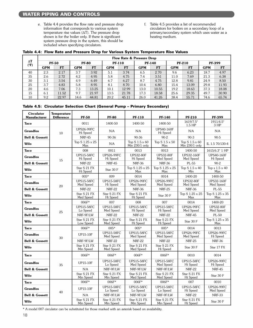
e. Table 4.4 provides the flow rate and pressure dropinformation that corresponds to various systemtemperature rise values (!T). The pressure dropshown is for the boiler only. If there is significantsystem pressure drop in the system, this should beincluded when specifying circulators.
f. Table 4.5 provides a list of recommendedcirculators for boilers on a secondary loop of aprimary/secondary system which uses water as aheating medium.
Table 4.4: Flow Rate and Pressure Drop for Various System Temperature Rise Values
!T(°F)
Flow Rate & Pressure DropPF-50 PF-80 PF-110 PF-140 PF-210 PF-399
GPM FT GPM FT GPM FT GPM FT GPM FT GPM FT40 2.3 2.17 3.7 3.92 5.1 3.74 6.5 2.70 9.6 6.23 18.7 4.9735 2.6 2.72 4.2 4.95 5.8 4.75 7.4 3.51 11.0 7.69 21.3 6.3830 3.1 3.54 4.9 6.49 6.7 6.27 8.7 4.75 12.8 9.81 24.9 8.5025 3.7 4.83 5.8 8.95 8.1 8.70 10.4 6.80 15.4 13.09 29.8 11.9320 4.6 7.06 7.3 13.25 10.1 12.99 13.0 10.55 19.2 18.63 37.3 18.0815 6.1 11.52 9.7 21.97 13.5 21.78 17.3 18.58 25.6 29.35 49.7 30.9010 9.2 22.97 14.6 44.81 20.2 45.11 26.0 41.26 38.4 55.71 74.6 65.74
Table 4.5: Circulator Selection Chart (General Pump – Primary Secondary)
* A model 007 circulator can be substituted for those marked with an asterisk based on availability.
CirculatorManufacturer
TemperatureDifference PF-50 PF-80 PF-110 PF-140 PF-210 PF-399
Taco
10
0011 1400-50 1400-50 1400-50 1619/7.5" 1.5 HP
1911/4.5" 3 HP
Grundfos UPS26-99FC Hi Speed N/A N/A UPS40-160F
Hi Speed N/A N/A
Bell & Gossett NRF-45 90-36 90-36 90-2 90-3 90-5
Wilo Top S 1.25 x 25Max N/A Top S 1.5.x 60
Min 230/1 onlyTop S 1.5 x 50
MaxTop S 1.5.x 60Min 230/1 only IL 1.5 70/130-4
Taco
15
008 0011 0013 0013 1400-50 1615/6.3" 1 HP
Grundfos UPS15-58FC Hi Speed
UPS26-99FC Hi Speed
UPS32-80F Hi Speed
UPS32-80F Med Speed
UPS32-160F Med Speed
UPS40-160F Hi Speed
Bell & Gossett NRF-22 NRF-45 NRF-36 NRF-36 PL-55 90-2
Wilo Star S 21 FX Hi Speed Star 30 F Top S 1.25 x 25
MaxTop S 1.25 x 25
MaxTop S 1.5 x 40
MinTop s 1.5 x 40
MaxTaco
20
005* 009 0014 0014 1400-20 1400-50
Grundfos UPS15-58FC Med Speed
UPS15-58FC Hi Speed
UPS26-99FC Med Speed
UPS26-99FC Med Speed
UPS32-80F Med Speed
UPS32-160F Med Speed
Bell & Gossett NRF-22 NRF-22 NRF-36 NRF-25 NRF-36 PL-55
Wilo Star S 21 FX Med Speed
Star S 21 FX Hi Speed
Star S 21 FX Hi Speed Star 30 F Top S 1.25 x 25
MaxTop S 1.25 x 35
MaxTaco
25
006F* 007 008 007 0014 1400-20
Grundfos UPS15-58FC Lo Speed
UPS15-58FC Med Speed
UPS15-58FC Hi Speed
UPS15-58FC Hi Speed
UPS26-99FC Med Speed
UPS32-80F Med Speed
Bell & Gossett NRF-9F/LW NRF-22 NRF-22 NRF-22 NRF-45 PL-50
Wilo Star S 21 FX Low Speed
Star S 21 FX Med Speed
Star S 21 FX Hi Speed
Star S 21 FX Hi Speed Star 30 F Top S 1.25 x 35
MaxTaco
30
006F* 005* 005* 005* 0014 0013
Grundfos UP15-10F UPS15-58FC Med Speed
UPS15-58FC Med Speed
UPS15-58FC Med Speed
UPS26-99FC Med Speed
UPS26-99FC Hi Speed
Bell & Gossett NRF-9F/LW NRF-22 NRF-22 NRF-22 NRF-25 NRF-36
Wilo Star S 21 FX Min Speed
Star S 21 FX Med Speed
Star S 21 FX Med Speed
Star S 21 FX Hi Speed Star 30 F Star 17 FX
Taco
35
006F* 006F* 006F* 006F* 0010 0014
Grundfos UP15-10F UPS15-58FC Lo Speed
UPS15-58FC Med Speed
UPS15-58FC Med Speed
UPS15-58FC Hi Speed
UPS26-99FC Hi Speed
Bell & Gossett N/A NRF-9F/LW NRF-9F/LW NRF-9F/LW NRF-22 NRF-45
Wilo Star S 21 FX Min Speed
Star S 21 FX Min Speed
Star S 21 FX Med Speed
Star S 21 FX Med Speed
Star S 21 FX Hi Speed Star 30 F
Taco
40
006F* 006F* 006F* 006F* 007 0010
Grundfos UP15-10F UPS15-58FC Lo Speed
UPS15-58FC Lo Speed
UPS15-58FC Lo Speed
UPS15-58FCHi Speed
UPS26-99FCMed Speed
Bell & Gossett N/A NRF-9F/LW NRF-9F/LW NRF-9F/LW NRF-22 NRF-33
Wilo Star S 21 FX Min Speed
Star S 21 FX Min Speed
Star S 21 FX Min Speed
Star S 21 FX Min Speed
Star S 21 FX Hi Speed Star 30 F
WATER PIPING AND CONTROLS
19
WATER PIPING AND CONTROLS
g. Special consideration must be given if a glycolbased anti-freeze solution is used as a heatingmedium. Propylene glycol has a higher viscositythan water, therefore the system pressure drop willbe higher.
10. Indirect Water Heater: An indirect water heater shouldbe piped to a dedicated zone. The PUREFIRE boilerprovides electrical terminals for connecting a domestichot water (DHW) circulator. Examples of piping forthe indirect water heater are shown under subsection“D”, System Piping of this section.
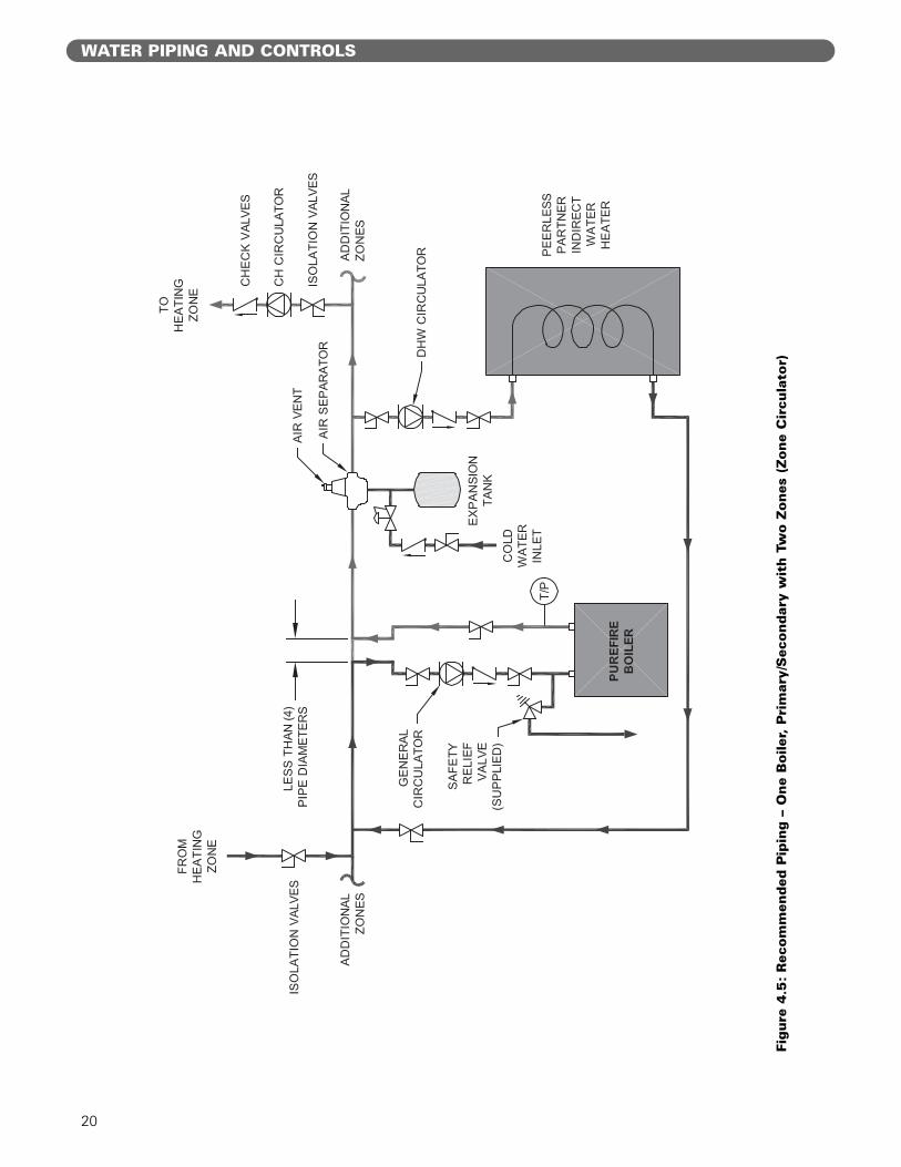
D. SYSTEM PIPING
1. Figure 4.5 shows a single boiler with multiple heatingzones. In this case, the DHW zone is piped in parallelto the heating zones on the primary loop.
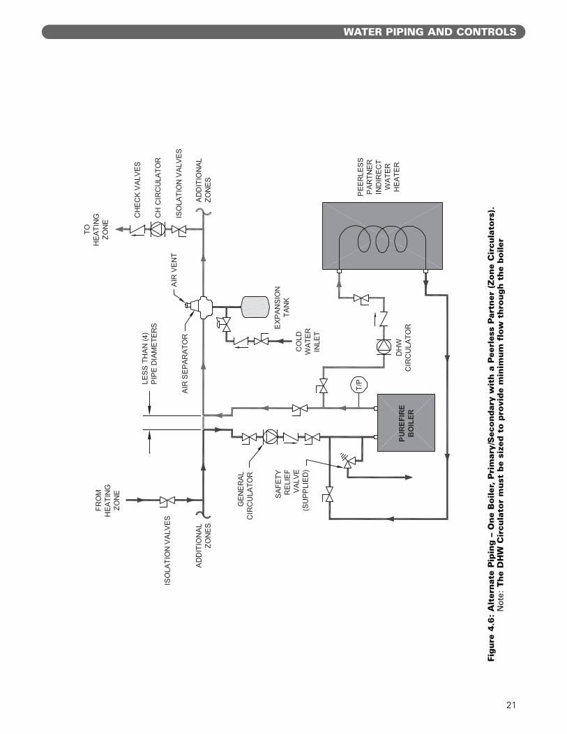
2. For a single boiler with one heating zone and oneDHW zone which utilizes an indirect water heater likethe Peerless Partner, pipe the boiler as shown inFigure 4.6. In systems like this, the DHW circulatormust be sized to provide the minimum flow ratethrough the boiler.
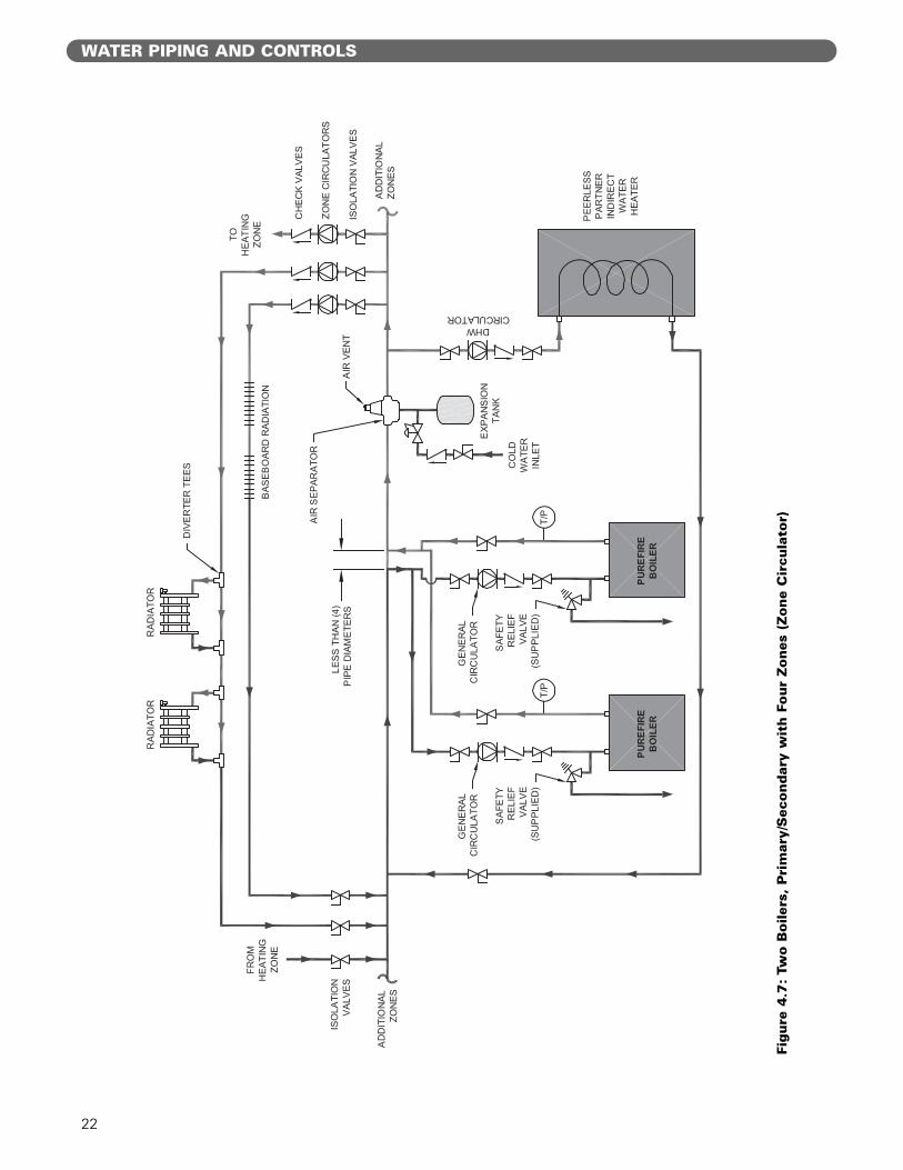
3. In Figure 4.7 an additional boiler is added and moreheating zones are shown. Notice that the two boilersare piped in parallel on the secondary loop. Thismaximizes the efficiency of the boilers since the lowesttemperature system water is returning to both boilers.
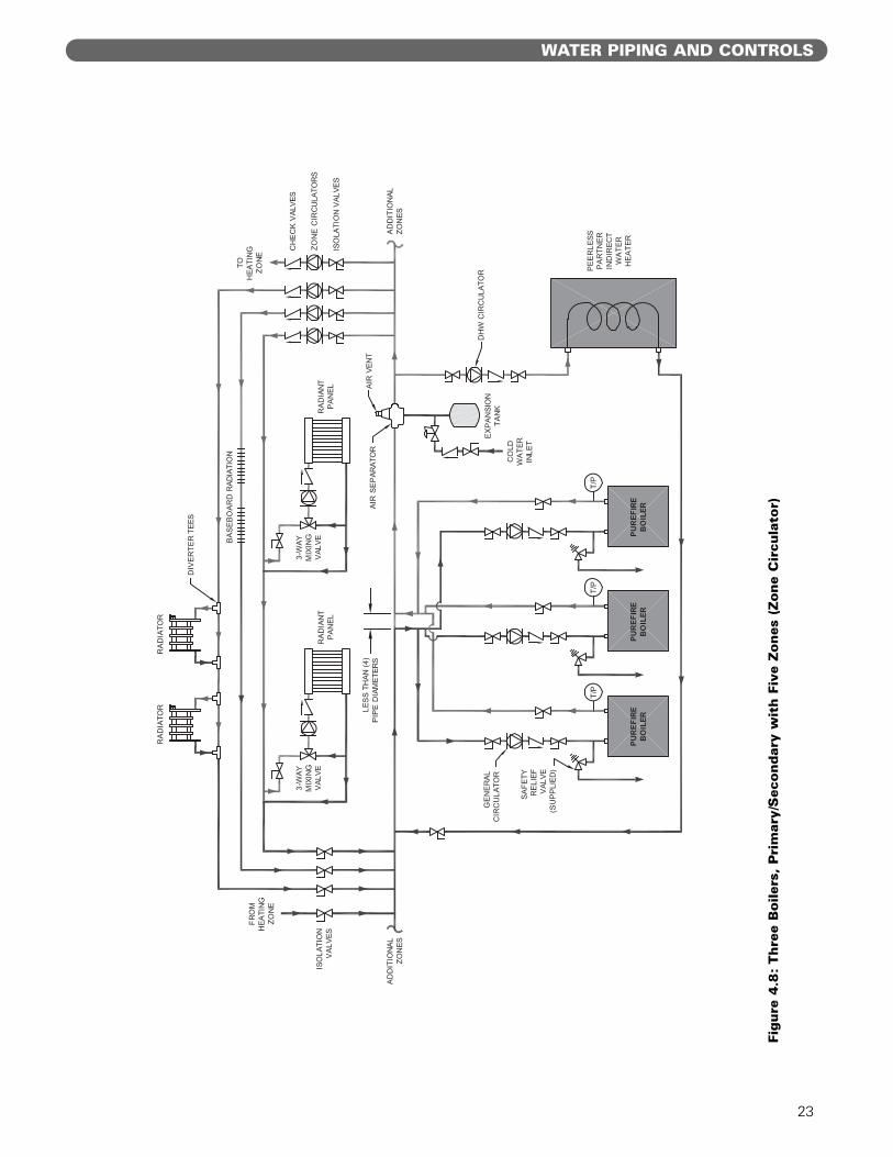
4. Figure 4.8 shows a multiple boiler system with severaldifferent types of heat distribution units. This systemillustrates how different temperature zones can besupplied from the same source by blending supplyand return water to the zone.
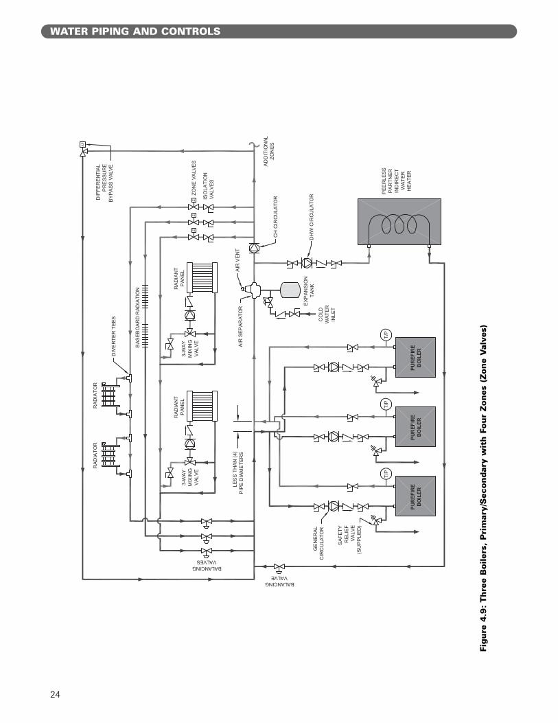
5. In Figure 4.9 zone valves are used instead of zonecirculators. Notice that the system is piped usingreverse return piping to help balance the flow throughthe zones. If the zone lengths vary balancing valvesare required on each loop.
E. FREEZE PROTECTION
1. Glycol for hydronic applications is specially formulatedfor heating systems. It includes inhibitors which preventthe glycol from attacking metallic system components.Make sure that the system fluid is checked for correctglycol concentration and inhibitor level.
2. Use only inhibited polypropylene glycol solutions ofup to 50% by volume. Ethylene glycol is toxic andcan chemically attack gaskets and seals used inhydronic system.
3. The anti-freeze solution should be tested at least onceper year and as recommended by the manufacturer ofthe product.
4. Anti-freeze solutions expand more than water. Forexample, a 50% by volume solution expands 4.8%with a 148°F temperature rise while water expandsabout 3% for the same temperature increase.Allowance for this expansion must be considered insizing expansion tanks and related components.
5. The flow rate in systems utilizing glycol solutionsshould be higher than in a water system tocompensate for decreased heating capacity of the fluid.
6. Due to increased flow rate and fluid viscosity, thecirculator head requirement will increase. Contact thepump manufacturer to correctly size the circulator fora particular application based on the glycolconcentration and heating requirements.
7. A strainer, sediment trap, or some other means forcleaning the piping system must be provided. Itshould be located in the return line upstream of theboiler and must be cleaned frequently during theinitial operation of the system. Glycol is likely toremove mill scale from new pipe in new installations.
8. Glycol solution is expensive and leaks should beavoided. Weld or solder joints should be used wherepossible and threaded joints should be avoided.Make-up water should not be added to the systemautomatically when glycol solution is used. Addingmake-up water will dilute the system and reduce theability of the solution to protect from freezing.
9. Check local regulations to see if systems containingglycol solutions must include a back-flow preventer orrequire that the glycol system be isolated from thewater supply.
10. Do not use galvanized pipe in glycol systems.
11. Use water that is low in mineral content and makesure that there are no petroleum products in thesolution.a. Less than 50 ppm of calciumb. Less than 50 ppm of magnesiumc. Less than 100 ppm (5 grains/gallon) of total
hardnessd. Less than 25 ppm of chloridee. Less than 25 ppm of sulfate
12. Check with the local water supplier for chemicalproperties of the water.
13. The following test will determine if the water is of theappropriate hardness. Collect a sample of 50% waterto 50% propylene glycol. Let the solution stand for 8-12 hours shaking it occasionally. If white sedimentforms, the water is too hard and should not be usedto dilute the glycol.
14. Mix the solution at room temperature.
15. Do not use a chromate treatment.
16. Refer to Technical Topics #2a published by theHydronics Institute for further glycol systemconsiderations.
The circulator sizing given is for primary/secondaryinstallations only. The system circulators must besized based on the flow and pressure droprequirements of the system.
NOTICE
20
WATER PIPING AND CONTROLS
Figure
4.5
:R
ecom
men
ded
Pip
ing –
One
Boile
r, P
rim
ary/
Sec
ondar
y w
ith T
wo Z
ones
(Zone
Cir
cula
tor)
21
WATER PIPING AND CONTROLS
Figure
4.6
:A
lter
nat
e P
ipin
g –
One
Boile
r, P
rim
ary/
Sec
ondar
y w
ith a
Pee
rles
s P
artn
er (
Zone
Cir
cula
tors
).N
ote:
The
DH
W C
ircu
lato
r m
ust
be
size
d t
o p
rovi
de
min
imum
flo
w t
hro
ugh t
he
boile
r
22
WATER PIPING AND CONTROLS
Figure
4.7
:Tw
o B
oile
rs,
Pri
mar
y/S
econdar
y w
ith F
our
Zones
(Zone
Cir
cula
tor)
23
Figure
4.8
:Thre
e B
oile
rs,
Pri
mar
y/S
econdar
y w
ith F
ive
Zones
(Zone
Cir
cula
tor)
WATER PIPING AND CONTROLS
24
WATER PIPING AND CONTROLS
Figure
4.9
:Thre
e B
oile
rs,
Pri
mar
y/S
econdar
y w
ith F
our
Zones
(Zone
Val
ves)
25
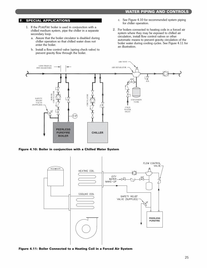
F. SPECIAL APPLICATIONS
1. If the PUREFIRE boiler is used in conjunction with achilled medium system, pipe the chiller in a separatesecondary loop.a. Assure that the boiler circulator is disabled during
chiller operation so that chilled water does notenter the boiler.
b. Install a flow control valve (spring check valve) toprevent gravity flow through the boiler.
c. See Figure 4.10 for recommended system pipingfor chiller operation.
2. For boilers connected to heating coils in a forced airsystem where they may be exposed to chilled aircirculation, install flow control valves or otherautomatic means to prevent gravity circulation of theboiler water during cooling cycles. See Figure 4.11 foran illustration.
WATER PIPING AND CONTROLS
Figure 4.10: Boiler in conjunction with a Chilled Water System
Figure 4.11: Boiler Connected to a Heating Coil in a Forced Air System
26
A. GENERAL
1. All fuel piping to the PUREFIRE boiler is to be inaccordance with local codes. In the absence of localregulations refer to the National Fuel Gas Code, ANSIZ223.1/NFPA 54.
2. Size and install fuel piping to provide a supply of gassufficient to meet the maximum demand of allappliances supplied by the piping.
B. FUEL LINE SIZING
1. The required flow rate of gas fuel to the boiler can bedetermined by the following.
The gas heating value can be supplied by the gassupplier.
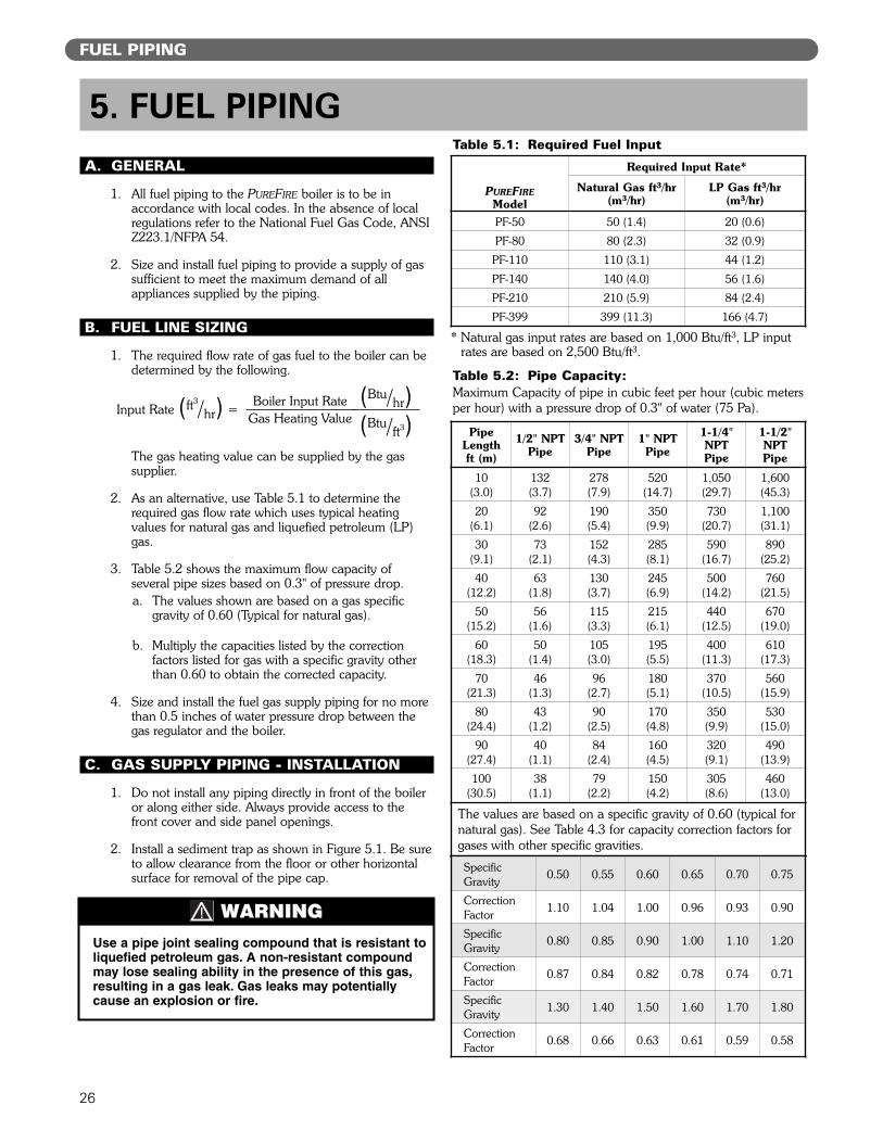
2. As an alternative, use Table 5.1 to determine therequired gas flow rate which uses typical heatingvalues for natural gas and liquefied petroleum (LP)gas.
3. Table 5.2 shows the maximum flow capacity ofseveral pipe sizes based on 0.3" of pressure drop.a. The values shown are based on a gas specific
gravity of 0.60 (Typical for natural gas).
b. Multiply the capacities listed by the correctionfactors listed for gas with a specific gravity otherthan 0.60 to obtain the corrected capacity.
4. Size and install the fuel gas supply piping for no morethan 0.5 inches of water pressure drop between thegas regulator and the boiler.
C. GAS SUPPLY PIPING - INSTALLATION
1. Do not install any piping directly in front of the boileror along either side. Always provide access to thefront cover and side panel openings.
2. Install a sediment trap as shown in Figure 5.1. Be sureto allow clearance from the floor or other horizontalsurface for removal of the pipe cap.
* Natural gas input rates are based on 1,000 Btu/ft3, LP inputrates are based on 2,500 Btu/ft3.
FUEL PIPING
5. FUEL PIPING
Use a pipe joint sealing compound that is resistant toliquefied petroleum gas. A non-resistant compoundmay lose sealing ability in the presence of this gas,resulting in a gas leak. Gas leaks may potentiallycause an explosion or fire.
WARNING
PUREFIREModel
Required Input Rate*
Natural Gas ft3/hr(m3/hr)
LP Gas ft3/hr(m3/hr)
PF-50 50 (1.4) 20 (0.6)
PF-80 80 (2.3) 32 (0.9)
PF-110 110 (3.1) 44 (1.2)
PF-140 140 (4.0) 56 (1.6)
PF-210 210 (5.9) 84 (2.4)
PF-399 399 (11.3) 166 (4.7)
Table 5.1: Required Fuel Input
PipeLengthft (m)
1/2" NPTPipe
3/4" NPTPipe
1" NPTPipe
1-1/4"NPTPipe
1-1/2"NPTPipe
10(3.0)
132(3.7)
278(7.9)
520(14.7)
1,050(29.7)
1,600(45.3)
20(6.1)
92(2.6)
190(5.4)
350(9.9)
730(20.7)
1,100(31.1)
30(9.1)
73(2.1)
152(4.3)
285(8.1)
590(16.7)
890(25.2)
40(12.2)
63(1.8)
130(3.7)
245(6.9)
500(14.2)
760(21.5)
50(15.2)
56(1.6)
115(3.3)
215(6.1)
440(12.5)
670(19.0)
60(18.3)
50(1.4)
105(3.0)
195(5.5)
400(11.3)
610(17.3)
70(21.3)
46(1.3)
96(2.7)
180(5.1)
370(10.5)
560(15.9)
80(24.4)
43(1.2)
90(2.5)
170(4.8)
350(9.9)
530(15.0)
90(27.4)
40(1.1)
84(2.4)
160(4.5)
320(9.1)
490(13.9)
100(30.5)
38(1.1)
79(2.2)
150(4.2)
305(8.6)
460(13.0)
The values are based on a specific gravity of 0.60 (typical fornatural gas). See Table 4.3 for capacity correction factors forgases with other specific gravities.
SpecificGravity 0.50 0.55 0.60 0.65 0.70 0.75
CorrectionFactor 1.10 1.04 1.00 0.96 0.93 0.90
SpecificGravity 0.80 0.85 0.90 1.00 1.10 1.20
CorrectionFactor 0.87 0.84 0.82 0.78 0.74 0.71
SpecificGravity 1.30 1.40 1.50 1.60 1.70 1.80
CorrectionFactor 0.68 0.66 0.63 0.61 0.59 0.58
Table 5.2: Pipe Capacity:Maximum Capacity of pipe in cubic feet per hour (cubic metersper hour) with a pressure drop of 0.3" of water (75 Pa).Boiler Input Rate
Gas Heating ValueInput Rate (ft!/hr) =
(Btu/hr)(Btu/ft!)
27
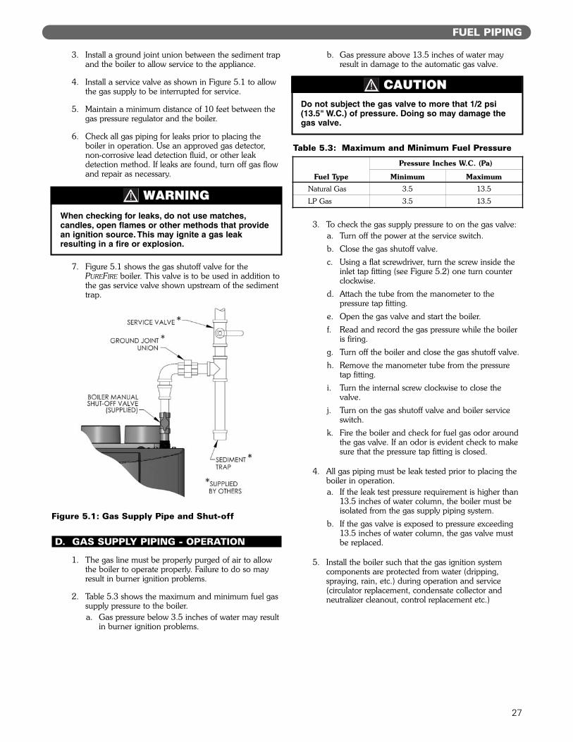
3. Install a ground joint union between the sediment trapand the boiler to allow service to the appliance.
4. Install a service valve as shown in Figure 5.1 to allowthe gas supply to be interrupted for service.
5. Maintain a minimum distance of 10 feet between thegas pressure regulator and the boiler.
6. Check all gas piping for leaks prior to placing theboiler in operation. Use an approved gas detector,non-corrosive lead detection fluid, or other leakdetection method. If leaks are found, turn off gas flowand repair as necessary.
7. Figure 5.1 shows the gas shutoff valve for thePUREFIRE boiler. This valve is to be used in addition tothe gas service valve shown upstream of the sedimenttrap.
D. GAS SUPPLY PIPING - OPERATION
1. The gas line must be properly purged of air to allowthe boiler to operate properly. Failure to do so mayresult in burner ignition problems.
2. Table 5.3 shows the maximum and minimum fuel gassupply pressure to the boiler.a. Gas pressure below 3.5 inches of water may result
in burner ignition problems.
b. Gas pressure above 13.5 inches of water mayresult in damage to the automatic gas valve.
3. To check the gas supply pressure to on the gas valve:a. Turn off the power at the service switch.b. Close the gas shutoff valve.c. Using a flat screwdriver, turn the screw inside the
inlet tap fitting (see Figure 5.2) one turn counterclockwise.
d. Attach the tube from the manometer to thepressure tap fitting.
e. Open the gas valve and start the boiler.f. Read and record the gas pressure while the boiler
is firing.g. Turn off the boiler and close the gas shutoff valve.h. Remove the manometer tube from the pressure
tap fitting.i. Turn the internal screw clockwise to close the
valve.j. Turn on the gas shutoff valve and boiler service
switch.k. Fire the boiler and check for fuel gas odor around
the gas valve. If an odor is evident check to makesure that the pressure tap fitting is closed.
4. All gas piping must be leak tested prior to placing theboiler in operation.a. If the leak test pressure requirement is higher than
13.5 inches of water column, the boiler must beisolated from the gas supply piping system.
b. If the gas valve is exposed to pressure exceeding13.5 inches of water column, the gas valve mustbe replaced.
5. Install the boiler such that the gas ignition systemcomponents are protected from water (dripping,spraying, rain, etc.) during operation and service(circulator replacement, condensate collector andneutralizer cleanout, control replacement etc.)
FUEL PIPING
When checking for leaks, do not use matches,candles, open flames or other methods that providean ignition source. This may ignite a gas leakresulting in a fire or explosion.
WARNING
Do not subject the gas valve to more that 1/2 psi(13.5" W.C.) of pressure. Doing so may damage thegas valve.
CAUTION
Fuel Type
Pressure Inches W.C. (Pa)
Minimum MaximumNatural Gas 3.5 13.5
LP Gas 3.5 13.5
Table 5.3: Maximum and Minimum Fuel Pressure
Figure 5.1: Gas Supply Pipe and Shut-off
E. MAIN GAS VALVE - OPERATION
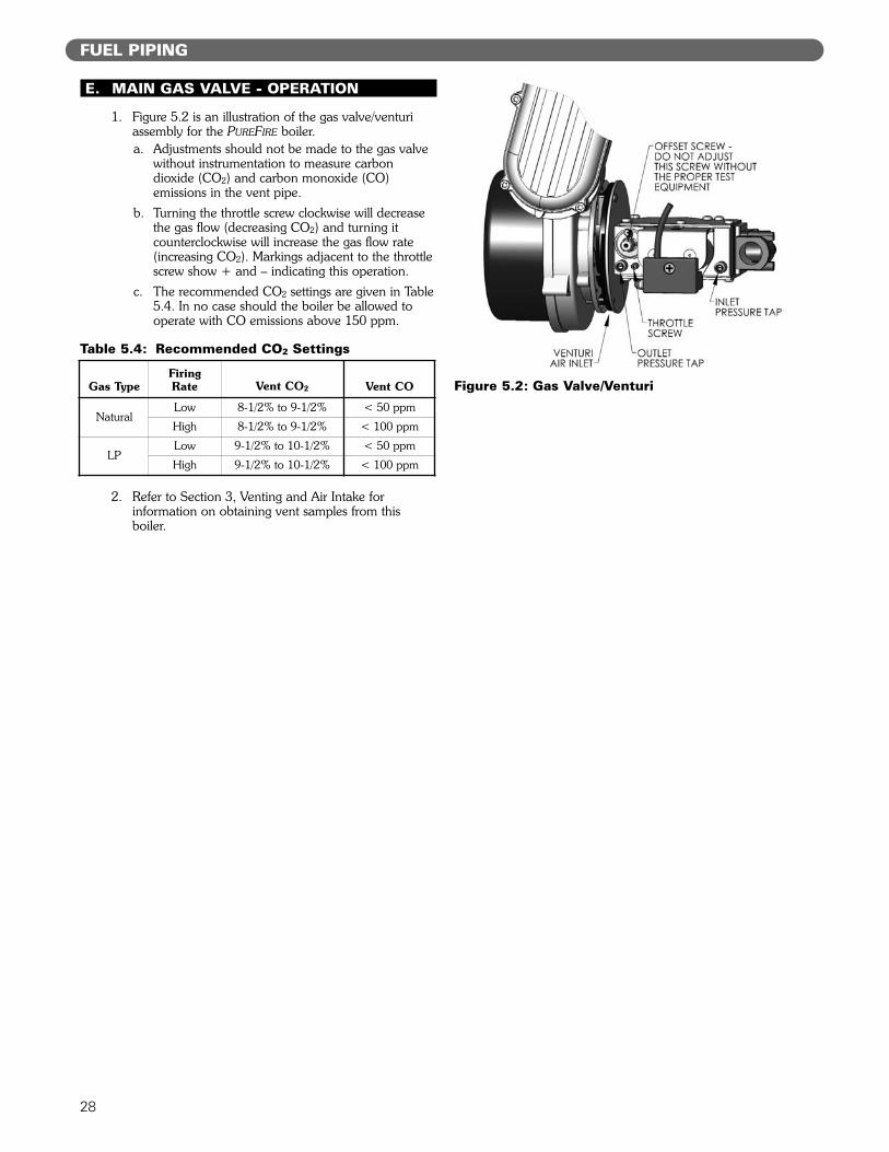
1. Figure 5.2 is an illustration of the gas valve/venturiassembly for the PUREFIRE boiler.a. Adjustments should not be made to the gas valve
without instrumentation to measure carbondioxide (CO2) and carbon monoxide (CO)emissions in the vent pipe.
b. Turning the throttle screw clockwise will decreasethe gas flow (decreasing CO2) and turning itcounterclockwise will increase the gas flow rate(increasing CO2). Markings adjacent to the throttlescrew show + and – indicating this operation.
c. The recommended CO2 settings are given in Table5.4. In no case should the boiler be allowed tooperate with CO emissions above 150 ppm.
2. Refer to Section 3, Venting and Air Intake forinformation on obtaining vent samples from thisboiler.
28
FUEL PIPING
Figure 5.2: Gas Valve/VenturiGas TypeFiring Rate Vent CO2 Vent CO
NaturalLow 8-1/2% to 9-1/2% < 50 ppm
High 8-1/2% to 9-1/2% < 100 ppm
LPLow 9-1/2% to 10-1/2% < 50 ppm
High 9-1/2% to 10-1/2% < 100 ppm
Table 5.4: Recommended CO2 Settings
29
A. GENERAL
1. The disposal of all condensate into public sewagesystems is to be in accordance with local codes andregulations. In the absence of such codes, follow theseinstructions.
2. Proper piping and removal of condensation fromcombustion is critical to the operation of a condensingappliance. Follow these instructions carefully to assurethat your PUREFIRE boiler operates correctly.
3. Depending on several factors, the condensate fromgas fired condensing appliances may have a pH valueas low as 2.5 (similar to cola soft drinks). Some localcodes require the use of neutralization equipment totreat acidic condensate.
B. CONDENSATE SYSTEM
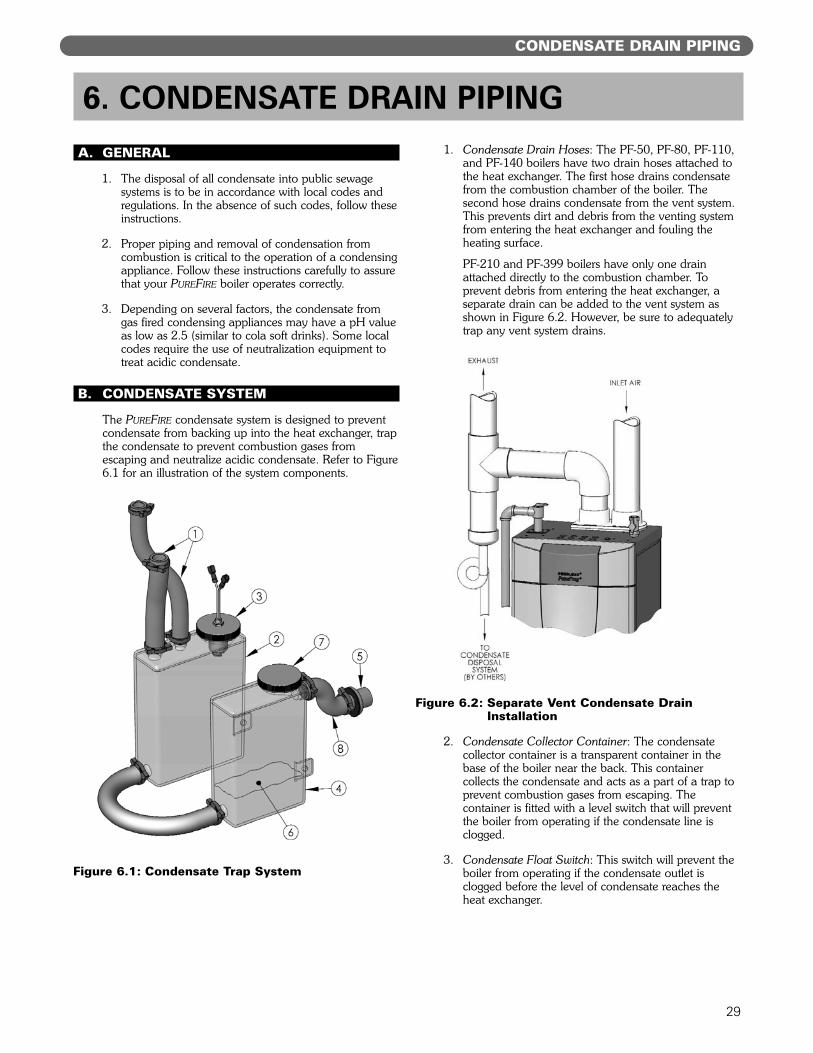
The PUREFIRE condensate system is designed to preventcondensate from backing up into the heat exchanger, trapthe condensate to prevent combustion gases fromescaping and neutralize acidic condensate. Refer to Figure6.1 for an illustration of the system components.
1. Condensate Drain Hoses: The PF-50, PF-80, PF-110,and PF-140 boilers have two drain hoses attached tothe heat exchanger. The first hose drains condensatefrom the combustion chamber of the boiler. Thesecond hose drains condensate from the vent system.This prevents dirt and debris from the venting systemfrom entering the heat exchanger and fouling theheating surface.
PF-210 and PF-399 boilers have only one drainattached directly to the combustion chamber. Toprevent debris from entering the heat exchanger, aseparate drain can be added to the vent system asshown in Figure 6.2. However, be sure to adequatelytrap any vent system drains.
2. Condensate Collector Container: The condensatecollector container is a transparent container in thebase of the boiler near the back. This containercollects the condensate and acts as a part of a trap toprevent combustion gases from escaping. Thecontainer is fitted with a level switch that will preventthe boiler from operating if the condensate line isclogged.
3. Condensate Float Switch: This switch will prevent theboiler from operating if the condensate outlet isclogged before the level of condensate reaches theheat exchanger.
CONDENSATE DRAIN PIPING
6. CONDENSATE DRAIN PIPING
Figure 6.1: Condensate Trap System
Figure 6.2: Separate Vent Condensate Drain Installation
30
4. Condensate Neutralizer Container: The condensateneutralizer container is an additional transparentcontainer near the front of the boiler. Fill thiscontainer with the condensate neutralizer provided.The neutralizer will be consumed during normaloperation and should be checked occasionally todetermine if additional neutralizer is necessary.Neutralizer is available in 1 lb bags (#54159) fromyour PB Heat Distributor.
5. Bulkhead fitting: The bulkhead fitting allows thecondensate tubing to pass through the jacket withoutproviding a path for leakage from the jacket. A PVCTEE is to be attached to the outlet of this fitting toprevent siphoning of the trap.
6. Neutralizer: Condensate neutralizer is provided in apackage with the boiler to fill the condensateneutralizer container (Item 4).
7. Neutralizer Cap: This cap provides access for addingand inspecting the condensate neutralizer.
8. Condensate Drain Tube: This pre-formed tubeconnects the condensate system to the bulkheadfitting for attachment to an external drain.
C. CONDENSATE DRAIN PIPE MATERIAL
The condensate drain is to be piped using PVC,polypropylene, or other material resistant to acidiccondensate. Do not use steel, brass or galvanized pipe forthis purpose. The acidic condensate will attack mostmetals and corrode.
D. CONDENSATE DRAIN PIPE SIZING
The bulkhead fitting for condensate connection is for 3/4"schedule 40 PVC Pipe. Be sure to use 3/4" or largertubing from the boiler to the drain.
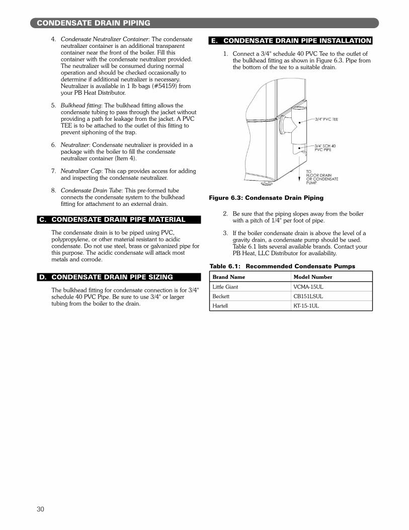
E. CONDENSATE DRAIN PIPE INSTALLATION
1. Connect a 3/4" schedule 40 PVC Tee to the outlet ofthe bulkhead fitting as shown in Figure 6.3. Pipe fromthe bottom of the tee to a suitable drain.
2. Be sure that the piping slopes away from the boilerwith a pitch of 1/4" per foot of pipe.
3. If the boiler condensate drain is above the level of agravity drain, a condensate pump should be used.Table 6.1 lists several available brands. Contact yourPB Heat, LLC Distributor for availability.
CONDENSATE DRAIN PIPING
Brand Name Model Number
Little Giant VCMA-15UL
Beckett CB151LSUL
Hartell KT-15-1UL
Table 6.1: Recommended Condensate Pumps
Figure 6.3: Condensate Drain Piping
31
A. GENERAL
This appliance is to be wired in accordance with localcodes and regulations as defined by the Authority havingjurisdiction. In the absence of such local codes, thePUREFIRE boiler is to be wired in accordance with the latestedition of the National Electrical Code, ANSI/NFPA 70.
B. CUSTOMER CONNECTIONS
1. Electrical knockouts are provided on the top panel ofthe boiler to connect supply wiring, circulator wiringand wiring to various instruments.
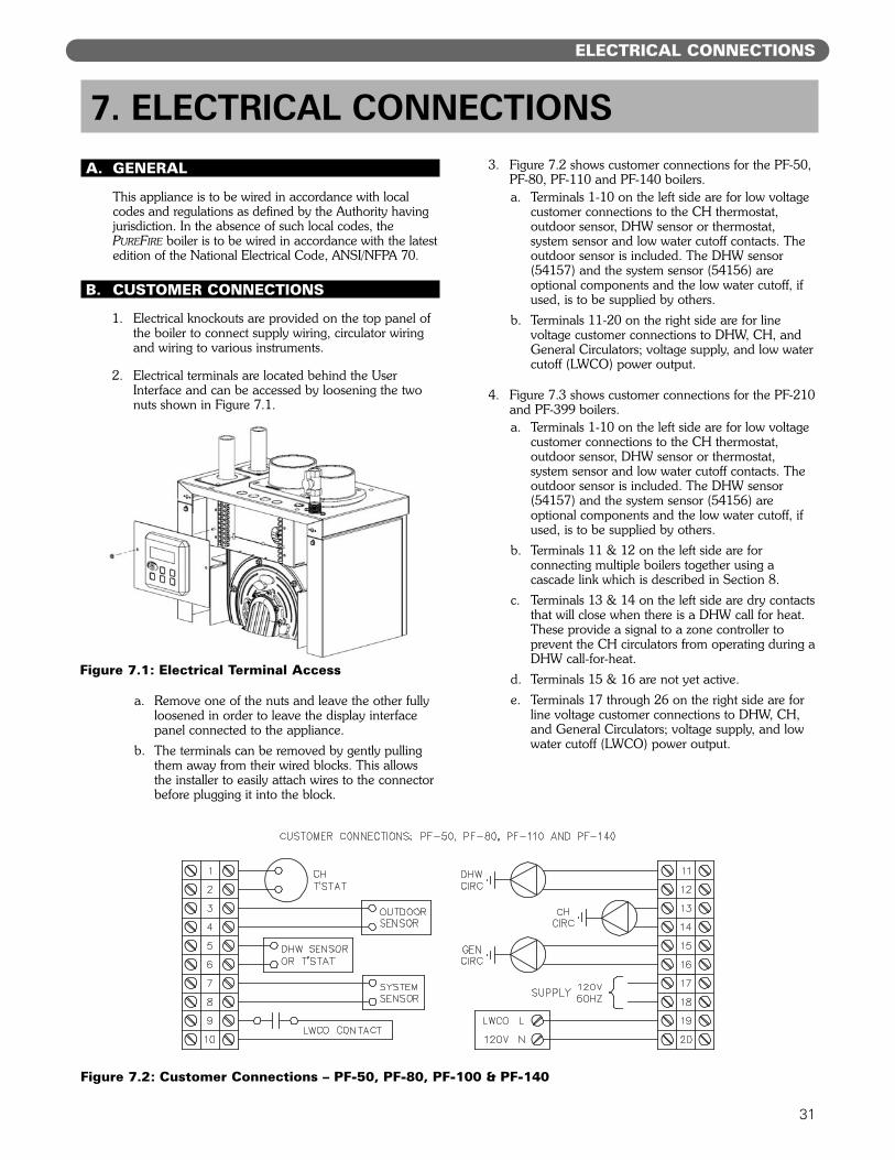
2. Electrical terminals are located behind the UserInterface and can be accessed by loosening the twonuts shown in Figure 7.1.
a. Remove one of the nuts and leave the other fullyloosened in order to leave the display interfacepanel connected to the appliance.
b. The terminals can be removed by gently pullingthem away from their wired blocks. This allowsthe installer to easily attach wires to the connectorbefore plugging it into the block.
3. Figure 7.2 shows customer connections for the PF-50,PF-80, PF-110 and PF-140 boilers.a. Terminals 1-10 on the left side are for low voltage
customer connections to the CH thermostat,outdoor sensor, DHW sensor or thermostat,system sensor and low water cutoff contacts. Theoutdoor sensor is included. The DHW sensor(54157) and the system sensor (54156) areoptional components and the low water cutoff, ifused, is to be supplied by others.
b. Terminals 11-20 on the right side are for linevoltage customer connections to DHW, CH, andGeneral Circulators; voltage supply, and low watercutoff (LWCO) power output.
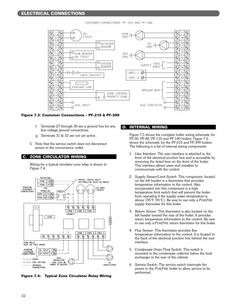
4. Figure 7.3 shows customer connections for the PF-210and PF-399 boilers.a. Terminals 1-10 on the left side are for low voltage
customer connections to the CH thermostat,outdoor sensor, DHW sensor or thermostat,system sensor and low water cutoff contacts. Theoutdoor sensor is included. The DHW sensor(54157) and the system sensor (54156) areoptional components and the low water cutoff, ifused, is to be supplied by others.
b. Terminals 11 & 12 on the left side are forconnecting multiple boilers together using acascade link which is described in Section 8.
c. Terminals 13 & 14 on the left side are dry contactsthat will close when there is a DHW call for heat.These provide a signal to a zone controller toprevent the CH circulators from operating during aDHW call-for-heat.
d. Terminals 15 & 16 are not yet active.e. Terminals 17 through 26 on the right side are for
line voltage customer connections to DHW, CH,and General Circulators; voltage supply, and lowwater cutoff (LWCO) power output.
ELECTRICAL CONNECTIONS
7. ELECTRICAL CONNECTIONS
Figure 7.1: Electrical Terminal Access
Figure 7.2: Customer Connections – PF-50, PF-80, PF-100 & PF-140
32
f. Terminals 27 through 30 are a ground bus for anyline voltage ground connections.
g. Terminals 31 & 32 are not yet active.
5. Note that the service switch does not disconnectpower to the convenience outlet.
C. ZONE CIRCULATOR WIRING
Wiring for a typical circulator zone relay is shown inFigure 7.4.
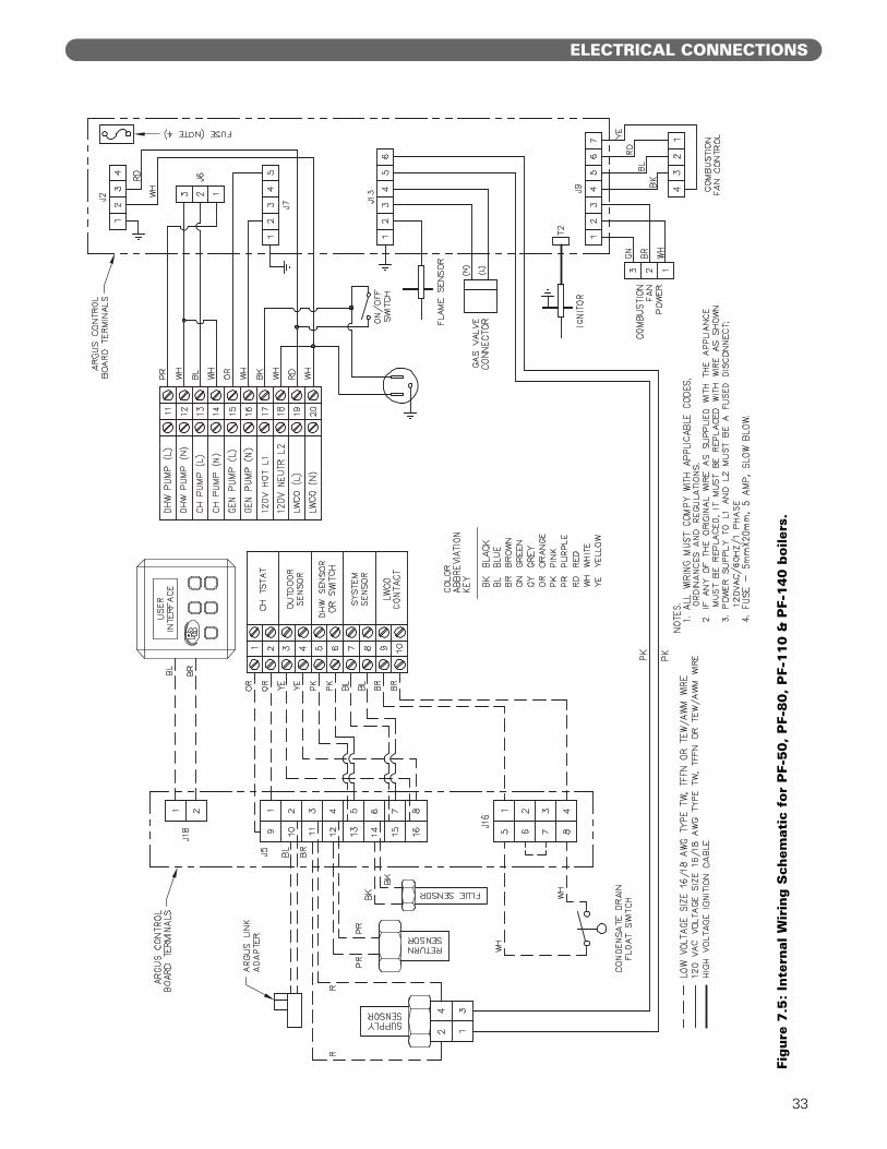
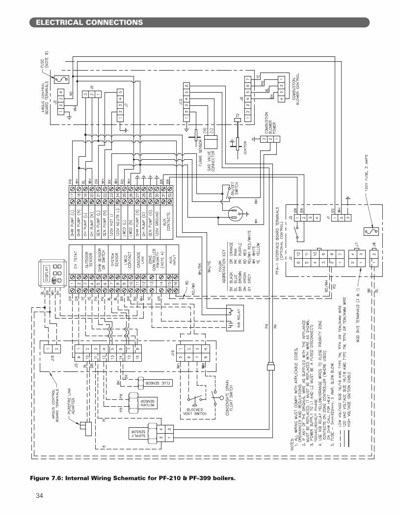
D. INTERNAL WIRING
Figure 7.5 shows the complete boiler wiring schematic forPF-50, PF-80, PF-110 and PF-140 boilers. Figure 7.6shows the schematic for the PF-210 and PF-399 boilers.The following is a list of internal wiring components.
1. User Interface: The user interface is attached to thefront of the electrical junction box and is accessible byremoving the tinted lens on the front of the boiler.This interface allows users and installers tocommunicate with the control.
2. Supply Sensor/Limit Switch: This component, locatedon the left header is a thermistor that providestemperature information to the control. Alsoincorporated into this component is a hightemperature limit switch that will prevent the boilerfrom operating if the supply water temperature isabove 195°F (91°C). Be sure to use only a PUREFIREsupply thermister for this boiler.
3. Return Sensor: This thermistor is also located on theleft header toward the rear of the boiler. It providesreturn temperature information to the control. Be sureto use only a PUREFIRE return thermistor for this boiler.
4. Flue Sensor: This thermistor provides fluetemperature information to the control. It is located inthe back of the electrical junction box behind the userinterface.
5. Condensate Drain Float Switch: This switch ismounted in the condensate collector below the heatexchanger in the rear of the cabinet.
6. Service Switch: The service switch interrupts thepower to the PUREFIRE boiler to allow service to beperformed.
ELECTRICAL CONNECTIONS
Figure 7.3: Customer Connections – PF-210 & PF-399
Figure 7.4: Typical Zone Circulator Relay Wiring
33
ELECTRICAL CONNECTIONS
Figure
7.5
:In
tern
al W
irin
g S
chem
atic
for
PF-
50,
PF-
80,
PF-
110 &
PF-
140 b
oile
rs.
34
Figure 7.6: Internal Wiring Schematic for PF-210 & PF-399 boilers.
ELECTRICAL CONNECTIONS
35
ELECTRICAL CONNECTIONS
7. Convenience Outlet: The convenience outlet isprovided for a condensate pump during operation. Itis not switched with the service switch to allow its usefor lighting during maintenance.
8. Flame Sensor: The flame sensor uses the principal offlame rectification to sense the burner flame. This islocated on the right side of the heat exchanger frontplate. After ignition, the control also senses flamethrough the ignition electrode.
9. Gas Valve: The gas valve is connected through aspecial cord and connector. The connector is attachedto the valve with a screw.
10. Ignition Electrode: This electrode is located on the leftside of the heat exchanger front plate. A 10,000 voltcharge is initiated by the control to provide a spark forlighting the burner. After the burner lights, and nospark is present, the control uses this electrode as asecond source of flame detection.
11. Combustion Air Fan: The combustion air fan has twoconnections. There is a 120 volt power connection (3-wire) and a low voltage control connection (4-wire).
12. Relay: A relay is provided in the PF-210 & PF-399 toallow the installer to provide a signal to the priorityzone of a zone controller to prevent CH zones frombeing activated when a call for DHW is present.
36
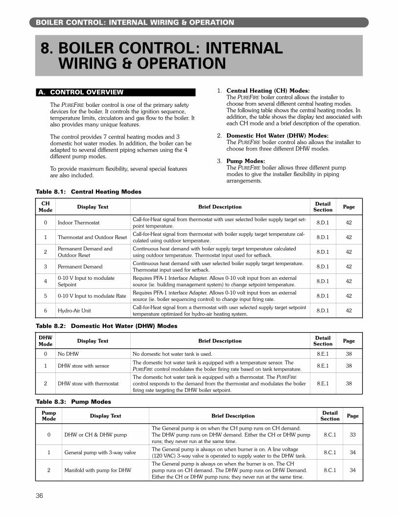
Table 8.3: Pump Modes
PumpMode Display Text Brief Description Detail
Section Page
0 DHW or CH & DHW pumpThe General pump is on when the CH pump runs on CH demand. The DHW pump runs on DHW demand. Either the CH or DHW pumpruns; they never run at the same time.
8.C.1 33
1 General pump with 3-way valve The General pump is always on when burner is on. A line voltage (120 VAC) 3-way valve is operated to supply water to the DHW tank. 8.C.1 34
2 Manifold with pump for DHWThe General pump is always on when the burner is on. The CH pump runs on CH demand. The DHW pump runs on DHW Demand.Either the CH or DHW pump runs; they never run at the same time.
8.C.1 34
A. CONTROL OVERVIEW
The PUREFIRE boiler control is one of the primary safetydevices for the boiler. It controls the ignition sequence,temperature limits, circulators and gas flow to the boiler. Italso provides many unique features.
The control provides 7 central heating modes and 3domestic hot water modes. In addition, the boiler can beadapted to several different piping schemes using the 4different pump modes.
To provide maximum flexibility, several special featuresare also included.
1. Central Heating (CH) Modes:The PUREFIRE boiler control allows the installer tochoose from several different central heating modes.The following table shows the central heating modes. Inaddition, the table shows the display text associated witheach CH mode and a brief description of the operation.
2. Domestic Hot Water (DHW) Modes:The PUREFIRE boiler control also allows the installer tochoose from three different DHW modes.
3. Pump Modes:The PUREFIRE boiler allows three different pumpmodes to give the installer flexibility in pipingarrangements.
BOILER CONTROL: INTERNAL WIRING & OPERATION
Table 8.1: Central Heating Modes
8. BOILER CONTROL: INTERNAL WIRING & OPERATION
CHMode Display Text Brief Description Detail
Section Page
0 Indoor Thermostat Call-for-Heat signal from thermostat with user selected boiler supply target set-point temperature. 8.D.1 42
1 Thermostat and Outdoor Reset Call-for-Heat signal from thermostat with boiler supply target temperature cal-culated using outdoor temperature. 8.D.1 42
2 Permanent Demand andOutdoor Reset
Continuous heat demand with boiler supply target temperature calculatedusing outdoor temperature. Thermostat input used for setback. 8.D.1 42
3 Permanent Demand Continuous heat demand with user selected boiler supply target temperature.Thermostat input used for setback. 8.D.1 42
4 0-10 V Input to modulateSetpoint
Requires PFA-1 Interface Adapter. Allows 0-10 volt input from an externalsource (ie. building management system) to change setpoint temperature. 8.D.1 42
5 0-10 V Input to modulate Rate Requires PFA-1 interface Adapter. Allows 0-10 volt input from an externalsource (ie. boiler sequencing control) to change input firing rate. 8.D.1 42
6 Hydro-Air Unit Call-for-Heat signal from a thermostat with user selected supply target setpointtemperature optimized for hydro-air heating system. 8.D.1 42
Table 8.2: Domestic Hot Water (DHW) Modes
DHWMode Display Text Brief Description Detail
Section Page
0 No DHW No domestic hot water tank is used. 8.E.1 38
1 DHW store with sensor The domestic hot water tank is equipped with a temperature sensor. ThePUREFIRE control modulates the boiler firing rate based on tank temperature. 8.E.1 38
2 DHW store with thermostatThe domestic hot water tank is equipped with a thermostat. The PUREFIRE
control responds to the demand from the thermostat and modulates the boilerfiring rate targeting the DHW boiler setpoint.
8.E.1 38
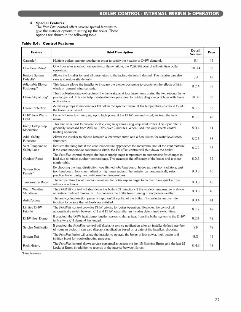
4. Special Features:The PUREFIRE control offers several special features togive the installer options in setting up the boiler. Theseoptions are shown in the following table.
37
BOILER CONTROL: INTERNAL WIRING & OPERATION
Table 8.4: Control Features
Feature Brief Description DetailSection Page
Cascade* Multiple boilers operate together in order to satisfy the heating or DHW demand. 8.I 44
One Hour Retry* One hour after a lockout on ignition or flame failure, the PUREFIRE control will reinitiate boiler operation.
10.B.4 53
Restore SystemDefaults*
Allows the installer to reset all parameters to the factory defaults if desired. The installer can alsosave and restore site defaults.
8.J 49
Adjustable BlowerPostpurge*
This feature allows the installer to increase the blower postpurge to counteract the effects of highwinds or unusual wind currents.
8.C.4 38
Flame Signal Log*This troubleshooting tool captures the flame signal at four increments during the two second flameproving period. This can help installers/service personnel to quickly diagnose problems with flamerectifications.
10.B.5 53
Freeze Protection Activates pumps if temperatures fall below the specified value. If the temperatures continue to fall,the boiler is activated.
8.C.3 38
DHW Tank WarmHold
Prevents boiler from ramping up to high power if the DHW demand is only to keep the tankwarm.
8.E.3 42
Ramp Delay StepModulation
This feature is used to prevent short cycling in systems using very small zones. The input rate isgradually increased from 20% to 100% over 2 minutes. When used, this only effects central heating operation.
8.D.4 41
Add’l SafetyFunctions
Allows the installer to choose between a low water cutoff and a flow switch for water level safetyshutdown.
8.C.5 38
Vent TemperatureSafety Limit
Reduces the firing rate if the vent temperature approaches the maximum limit of the vent material. If the vent temperature continues to climb, the PUREFIRE control will shut down the boiler.
8.C.2 38
Outdoor ResetThe PUREFIRE control changes the boiler supply target temperature to compensate for changes inload due to milder outdoor temperatures. This increases the efficiency of the boiler and is morecomfortable.
8.D.3 39
System TypePresets*
By choosing the heat distribution type (finned tube baseboard, hydro air, cast iron radiators, castiron baseboard, low mass radiant or high mass radiant) the installer can automatically select practical boiler design and mild weather temperatures.
8.D.3 40
Temperature Boost The temperature boost function increases the boiler supply target to recover more quickly from setback conditions.
8.D.3 40
Warm WeatherShutdown
The PUREFIRE control will shut down the boilers CH functions if the outdoor temperature is abovean installer defined maximum. This prevents the boiler from running during warm weather.
8.D.3 40
Anti-Cycling The anti-cycling function prevents rapid on/off cycling of the boiler. This includes an override function to be sure that all loads are satisfied.
8.D.4 41
Limited DHWPriority
The PUREFIRE control provides DHW priority for boiler operation. However, the control will automatically switch between CH and DHW loads after an installer determined switch time.
8.E.2 42
DHW Heat Dump If enabled, the DHW heat dump function serves to dump heat from the boiler system to the DHWtank after a CH demand has ended.
8.E.4 42
Service Notification If enabled, the PUREFIRE control will display a service notification after an installer defined numberof hours or cycles. It can also display a notification based on a date of the installers choosing.
8.F 42
System Test The PUREFIRE boiler will allow the installer to operate the boiler at low power, high power and ignition input for troubleshooting purposes.
8.G 43
Fault History The PUREFIRE control allows service personnel to access the last 15 Blocking Errors and the last 15Lockout Errors in addition to records of the interval between Errors.
8.H.3 43
*New features
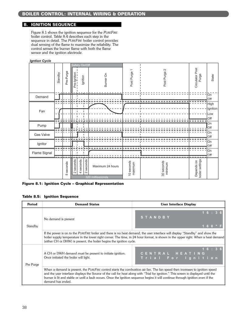
B. IGNITION SEQUENCE
Figure 8.1 shows the ignition sequence for the PUREFIREboiler control. Table 8.4 describes each step in thesequence in detail. The PUREFIRE boiler control providesdual sensing of the flame to maximize the reliability. Thecontrol senses the burner flame with both the flamesensor and the ignition electrode.
38
BOILER CONTROL: INTERNAL WIRING & OPERATION
Figure 8.1: Ignition Cycle – Graphical Representation
Off
Stat
e
OffOnOffOn
On
OnOffOn
IgnitionLowOff
Pump
Gas Valve
Ignitor
Flame Signal
Pre-
Purg
e
Stan
dby
Fan
Igntion Cycle
Demand
Pre-
Igni
tion
Igni
tion
Circ
ulat
or P
ost
Purg
e
Safety On/Off
Post
Pur
ge 1
Post
Pur
ge 2
Burn
er O
n
OffHigh
2 se
cond
s
4 se
cond
s
2 se
cond
s
Maximum 24 hours30
sec
onds
m
inim
um
Dep
ends
on
boile
r set
tings
320 milliseconds
5 se
cond
s
10 s
econ
ds
max
imum
Table 8.5: Ignition Sequence
Period Demand Status User Interface Display
Standby
No demand is present
If the power is on to the PUREFIRE boiler and there is no heat demand, the user interface will display “Standby” and show the boiler supply temperature in the lower right corner. The time, in 24 hour format, is shown in the upper right. When a heat demand(either CH or DHW) is present, the boiler begins the ignition cycle.
Pre Purge
A CH or DWH demand must be present to initiate ignition.Once initiated the boiler will light.
When a demand is present, the PUREFIRE control starts the combustion air fan. The fan speed then increases to ignition speed and the user interface displays the Source of the call for heat along with “Trial for ignition.” This screen is displayed until the burner is lit and stable or until a fault occurs. Once the ignition sequence begins it will continue through ignition even if thedemand has ended.
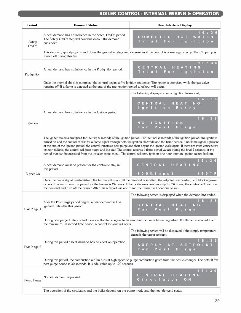
39
BOILER CONTROL: INTERNAL WIRING & OPERATION
Period Demand Status User Interface Display
SafetyOn/Off
A heat demand has no influence in the Safety On/Off period.The Safety On/Off step will continue even if the demand has ended.
This step very quickly opens and closes the gas valve relays and determines if the control is operating correctly. The CH pump isturned off during this test.
Pre-IgnitionA heat demand has no influence in the Pre-Ignition period.
Once the internal check is complete, the control begins a Pre-Ignition sequence. The igniter is energized while the gas valveremains off. If a flame is detected at the end of the pre-ignition period a lockout will occur.
Ignition
A heat demand has no influence in the Ignition period.
The following displays occur on ignition failure only.
The igniter remains energized for the first 4 seconds of the Ignition period. For the final 2 seconds of the Ignition period, the igniter isturned off and the control checks for a flame signal through both the ignition electrode and the flame sensor. If no flame signal is presentat the end of the Ignition period, the control initiates a post-purge and then begins the ignition cycle again. If there are three consecutiveignition failures, the control will post purge and lockout. The control records 4 flame signal values during the final 2 seconds of thisperiod that can be accessed from the installer status menu. The control will retry ignition one hour after an ignition failure lockout.
Burner On
A heat demand must be present for the control to stay in this period.
Once the flame signal is established, the burner will run until the demand is satisfied, the setpoint is exceeded, or a blocking erroroccurs. The maximum run period for the burner is 24 hours. If the boiler runs continuously for 24 hours, the control will overridethe demand and turn off the burner. After this a restart will occur and the burner will continue to run.
Post Purge 1
After the Post Purge period begins, a heat demand will beignored until after this period.
The following screen is displayed when the demand has ended.
During post purge 1, the control monitors the flame signal to be sure that the flame has extinguished. If a flame is detected afterthe maximum 10 second time period, a control lockout will occur.
Post Purge 2During this period a heat demand has no effect on operation.
The following screen will be displayed if the supply temperatureexceeds the target setpoint.
During this period, the combustion air fan runs at high speed to purge combustion gases from the heat exchanger. The default fanpost purge period is 30 seconds. It is adjustable up to 120 seconds.
Pump PurgeNo heat demand is present.
The operation of the circulators and the boiler depend on the pump mode and the heat demand status.
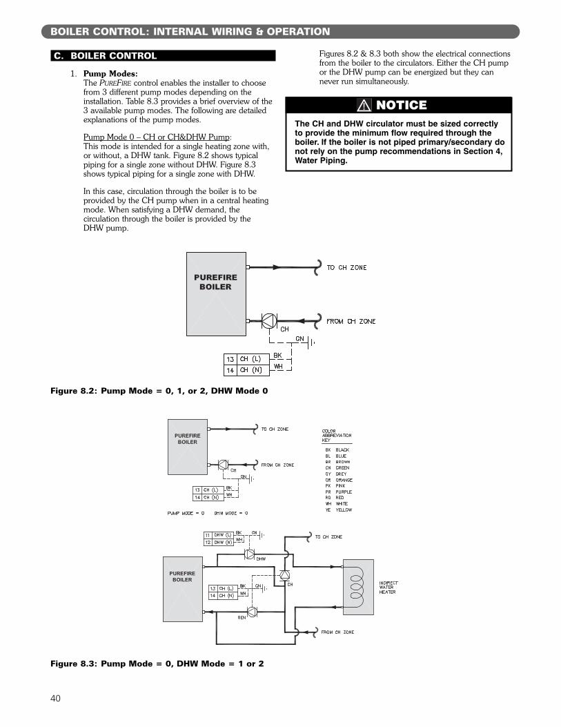
40
C. BOILER CONTROL
1. Pump Modes:The PUREFIRE control enables the installer to choosefrom 3 different pump modes depending on theinstallation. Table 8.3 provides a brief overview of the3 available pump modes. The following are detailedexplanations of the pump modes.
Pump Mode 0 – CH or CH&DHW Pump:This mode is intended for a single heating zone with,or without, a DHW tank. Figure 8.2 shows typicalpiping for a single zone without DHW. Figure 8.3shows typical piping for a single zone with DHW.
In this case, circulation through the boiler is to beprovided by the CH pump when in a central heatingmode. When satisfying a DHW demand, thecirculation through the boiler is provided by the DHW pump.
Figures 8.2 & 8.3 both show the electrical connectionsfrom the boiler to the circulators. Either the CH pumpor the DHW pump can be energized but they cannever run simultaneously.
BOILER CONTROL: INTERNAL WIRING & OPERATION
The CH and DHW circulator must be sized correctlyto provide the minimum flow required through theboiler. If the boiler is not piped primary/secondary donot rely on the pump recommendations in Section 4,Water Piping.
NOTICE
Figure 8.2: Pump Mode = 0, 1, or 2, DHW Mode 0
Figure 8.3: Pump Mode = 0, DHW Mode = 1 or 2
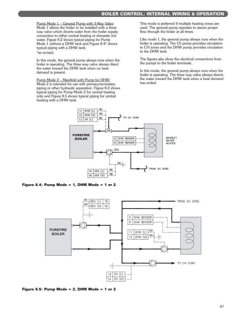
41
Pump Mode 1 – General Pump with 3-Way Valve:Mode 1 allows the boiler to be installed with a three way valve which diverts water from the boiler supplyconnection to either central heating or domestic hotwater. Figure 8.2 shows typical piping for Pump Mode 1 without a DHW tank and Figure 8.4* showstypical piping with a DHW tank.*as revised.
In this mode, the general pump always runs when theboiler is operating. The three-way valve always directthe water toward the DHW tank when no heatdemand is present.
Pump Mode 2 – Manifold with Pump for DHW:Mode 2 is intended for use with primary/secondarypiping or other hydraulic separation. Figure 8.2 showstypical piping for Pump Mode 2 for central heatingonly and Figure 8.5 shows typical piping for centralheating with a DHW tank.
This mode is preferred if multiple heating zones areused. The general pump operates to assure properflow through the boiler at all times.
Like mode 1, the general pump always runs when theboiler is operating. The Ch pump provides circulationto CH zones and the DHW pump provides circulationto the DHW tank.
The figures also show the electrical connections fromthe pumps to the boiler terminals.
In this mode, the general pump always runs when theboiler is operating. The three way valve always directsthe water toward the DHW tank when a heat demandhas ended.
BOILER CONTROL: INTERNAL WIRING & OPERATION
Figure 8.4: Pump Mode = 1, DHW Mode = 1 or 2
Figure 8.5: Pump Mode = 2, DHW Mode = 1 or 2
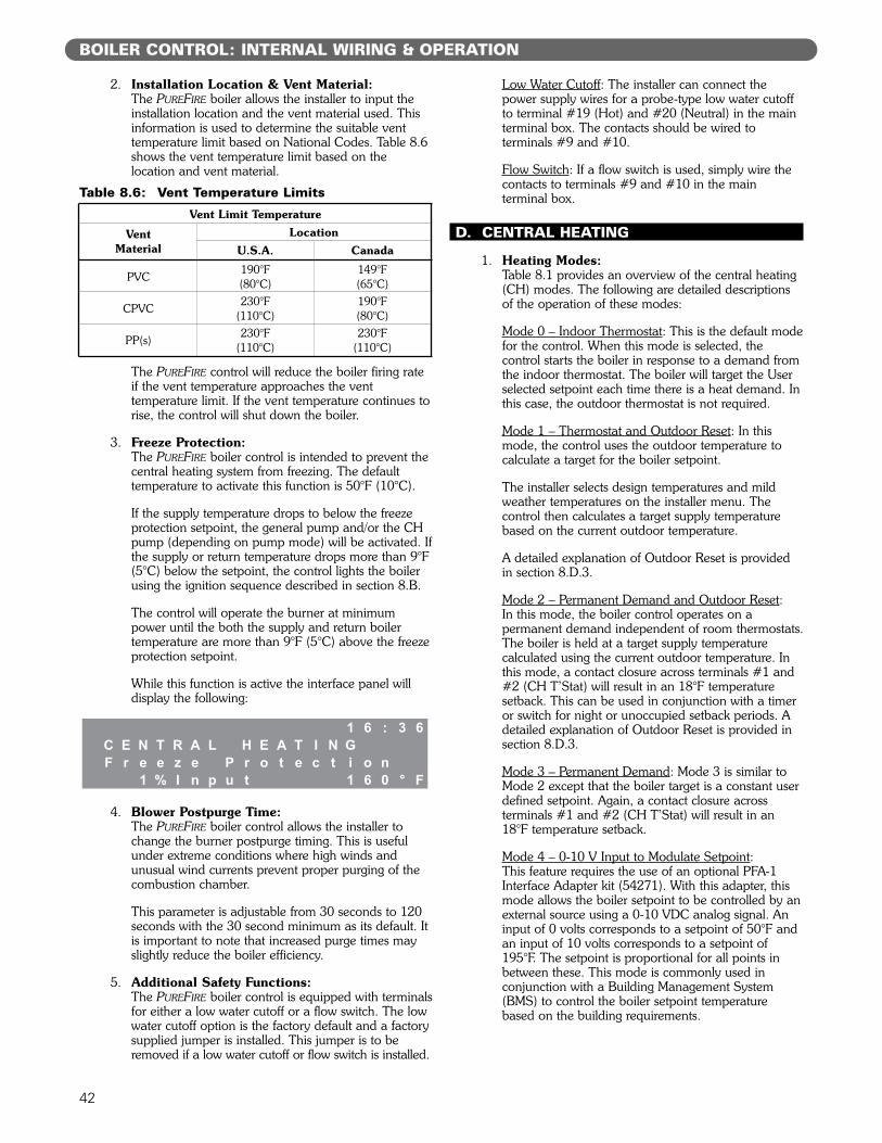
42
2. Installation Location & Vent Material:The PUREFIRE boiler allows the installer to input theinstallation location and the vent material used. Thisinformation is used to determine the suitable venttemperature limit based on National Codes. Table 8.6shows the vent temperature limit based on thelocation and vent material.
The PUREFIRE control will reduce the boiler firing rateif the vent temperature approaches the venttemperature limit. If the vent temperature continues torise, the control will shut down the boiler.
3. Freeze Protection:The PUREFIRE boiler control is intended to prevent thecentral heating system from freezing. The defaulttemperature to activate this function is 50°F (10°C).
If the supply temperature drops to below the freezeprotection setpoint, the general pump and/or the CHpump (depending on pump mode) will be activated. Ifthe supply or return temperature drops more than 9°F(5°C) below the setpoint, the control lights the boilerusing the ignition sequence described in section 8.B.
The control will operate the burner at minimumpower until the both the supply and return boilertemperature are more than 9°F (5°C) above the freezeprotection setpoint.
While this function is active the interface panel willdisplay the following:
4. Blower Postpurge Time:The PUREFIRE boiler control allows the installer tochange the burner postpurge timing. This is usefulunder extreme conditions where high winds andunusual wind currents prevent proper purging of thecombustion chamber.
This parameter is adjustable from 30 seconds to 120seconds with the 30 second minimum as its default. Itis important to note that increased purge times mayslightly reduce the boiler efficiency.
5. Additional Safety Functions:The PUREFIRE boiler control is equipped with terminalsfor either a low water cutoff or a flow switch. The lowwater cutoff option is the factory default and a factorysupplied jumper is installed. This jumper is to beremoved if a low water cutoff or flow switch is installed.
Low Water Cutoff: The installer can connect thepower supply wires for a probe-type low water cutoffto terminal #19 (Hot) and #20 (Neutral) in the mainterminal box. The contacts should be wired toterminals #9 and #10.
Flow Switch: If a flow switch is used, simply wire thecontacts to terminals #9 and #10 in the mainterminal box.
D. CENTRAL HEATING
1. Heating Modes:Table 8.1 provides an overview of the central heating(CH) modes. The following are detailed descriptionsof the operation of these modes:
Mode 0 – Indoor Thermostat: This is the default modefor the control. When this mode is selected, thecontrol starts the boiler in response to a demand fromthe indoor thermostat. The boiler will target the Userselected setpoint each time there is a heat demand. Inthis case, the outdoor thermostat is not required.
Mode 1 – Thermostat and Outdoor Reset: In thismode, the control uses the outdoor temperature tocalculate a target for the boiler setpoint.
The installer selects design temperatures and mildweather temperatures on the installer menu. Thecontrol then calculates a target supply temperaturebased on the current outdoor temperature.
A detailed explanation of Outdoor Reset is providedin section 8.D.3.
Mode 2 – Permanent Demand and Outdoor Reset: In this mode, the boiler control operates on apermanent demand independent of room thermostats.The boiler is held at a target supply temperaturecalculated using the current outdoor temperature. Inthis mode, a contact closure across terminals #1 and#2 (CH T’Stat) will result in an 18°F temperaturesetback. This can be used in conjunction with a timeror switch for night or unoccupied setback periods. Adetailed explanation of Outdoor Reset is provided insection 8.D.3.
Mode 3 – Permanent Demand: Mode 3 is similar toMode 2 except that the boiler target is a constant userdefined setpoint. Again, a contact closure acrossterminals #1 and #2 (CH T’Stat) will result in an18°F temperature setback.
Mode 4 – 0-10 V Input to Modulate Setpoint: This feature requires the use of an optional PFA-1Interface Adapter kit (54271). With this adapter, thismode allows the boiler setpoint to be controlled by anexternal source using a 0-10 VDC analog signal. Aninput of 0 volts corresponds to a setpoint of 50°F andan input of 10 volts corresponds to a setpoint of195°F. The setpoint is proportional for all points inbetween these. This mode is commonly used inconjunction with a Building Management System(BMS) to control the boiler setpoint temperaturebased on the building requirements.
BOILER CONTROL: INTERNAL WIRING & OPERATION
Table 8.6: Vent Temperature Limits
Vent Limit Temperature
VentMaterial
LocationU.S.A. Canada
PVC 190°F(80°C)
149°F(65°C)
CPVC 230°F(110°C)
190°F(80°C)
PP(s) 230°F(110°C)
230°F(110°C)
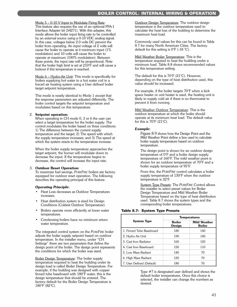
43
Mode 5 – 0-10 V Input to Modulate Firing Rate: This feature also requires the use of an optional PFA-1Interface Adapter kit (54271). With this adapter, thismode allows the boiler input firing rate to be controlledby an external source using a 0-10 VDC analog signal.In this case, voltages below 2.0 volts DC prevent theboiler from operating. An input voltage of 2 volts willcause the boiler to operate at it minimum input (1%modulation) and 10 volts will cause the boiler tooperate at maximum (100% modulation). Betweenthese points, the input rate will be proportional. Notethat the boiler high limit is set at 210°F and will cause alockout if this temperature is reached.
Mode 6 – Hydro-Air Unit: This mode is specifically forboilers supplying hot water to a hot water coil in aforced air heating system using a User defined boilertarget setpoint temperature.
This mode is nearly identical to Mode 1 except thatthe response parameters are adjusted differently. Theboiler control targets the setpoint temperature andmodulates based on this temperature.
2. Setpoint operation:When operating in CH mode 0, 3 or 6 the user canselect a target temperature for the boiler supply. Thecontrol modulates the boiler based on three conditions:1) The difference between the current supplytemperature and the target; 2) The speed with whichthe supply temperature increases; and 3) The speed atwhich the system reacts to the temperature increase.
When the boiler supply temperature approaches thetarget setpoint, the burner will modulate down todecrease the input. If the temperature begins todecrease, the control will increase the input rate.
3. Outdoor Reset Operation:To maximize fuel savings, PUREFIRE boilers are factoryequipped for outdoor reset operation. The followingdescribes the operating principal of this feature.
Operating Principle:• Heat Loss decreases as Outdoor Temperatures
increases.• Heat distribution system is sized for Design
Conditions (Coldest Outdoor Temperature).• Boilers operate more efficiently at lower water
temperatures.• Condensing boilers have no minimum return
water temperature.
The integrated control system on the PUREFIRE boileradjusts the boiler supply setpoint based on outdoortemperature. In the installer menu, under “CHSettings” there are two parameters that define thedesign point of the boiler. The design point representsthe conditions for which the boiler was sized.
Boiler Design Temperature: The boiler supplytemperature required to heat the building under itsdesign load is called Boiler Design Temperature. Forexample, if the building was designed with copperfinned tube baseboard with 180°F water, this is thedesign temperature that should be entered. Thefactory default for the Boiler Design Temperature is180°F (82°C).
Outdoor Design Temperature: The outdoor designtemperature is the outdoor temperature used tocalculate the heat loss of the building to determine themaximum heat load.
Commonly used values for this can be found in Table8.7 for many North American Cities. The factorydefault for this setting is 0°F (-18 °C).
Mild Weather Boiler Temperature: This is thetemperature required to heat the building under aminimum load. Table 8.8 shows recommended valuesfor this temperature setting.
The default for this is 70°F (21°C). However,depending on the type of heat distribution used, thisvalue should be increased.
For example, if the boiler targets 70°F when a kickspace heater or unit heater is used, the heating unit islikely to supply cold air if there is no thermostat toprevent it from running.
Mild Weather Outdoor Temperature: This is theoutdoor temperature at which the boiler shouldoperate at its minimum heat load. The default valuefor this is 70°F (21°C).
Example:Figure 8.9 shows how the Design Point and theMild Weather Point define a line used to calculateboiler supply temperature based on outdoortemperature.The design point is shown for an outdoor designtemperature of 0°F and a boiler design supplytemperature of 160°F. The mild weather point isshown for an outdoor temperature of 70°F and aboiler supply temperature of 95°F. From this, the PUREFIRE control calculates a boilersupply temperature of 130°F when the outdoortemperature is 32°F.System Type Presets: The PUREFIRE Control allowsthe installer to select preset values for BoilerDesign Temperature and Mild Weather BoilerTemperature based on the type of heat distributionused. Table 8.7 shows the system types and thecorresponding boiler temperatures.
Type #7 is designated user defined and shows thedefault boiler temperatures. Once this choice isselected, the installer can change the numbers asdesired.
BOILER CONTROL: INTERNAL WIRING & OPERATION
System TypeTemperatures
BoilerDesign
Mild WeatherBoiler
1. Finned Tube Baseboard 180 140
2. Hydro Air Unit 190 140
3. Cast Iron Radiator 160 120
4. Cast Iron Baseboard 150 110
5. Low Mass Radiant 140 70
6. High Mass Radiant 120 70
7. User Defined (Default) 180 70
Table 8.7: System Type Presets
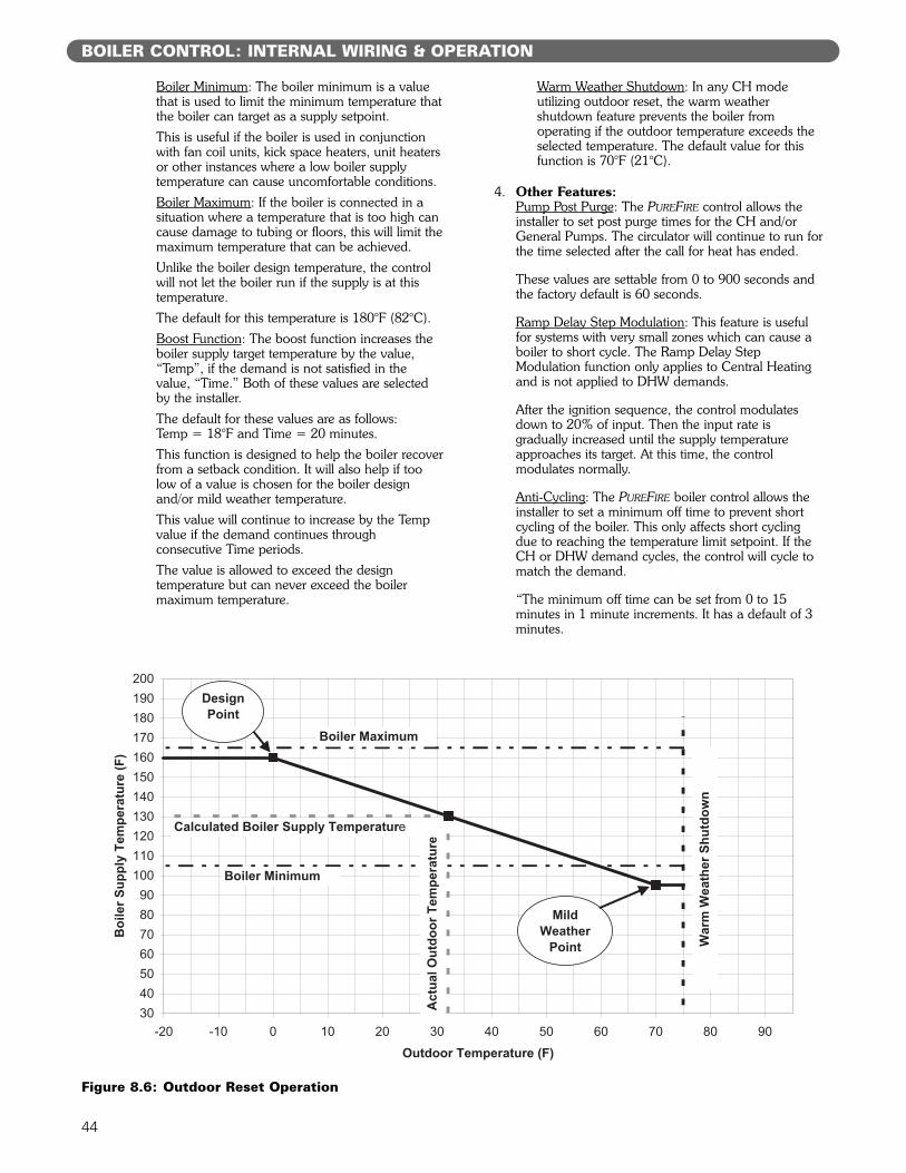
Boiler Minimum: The boiler minimum is a valuethat is used to limit the minimum temperature thatthe boiler can target as a supply setpoint.This is useful if the boiler is used in conjunctionwith fan coil units, kick space heaters, unit heatersor other instances where a low boiler supplytemperature can cause uncomfortable conditions.Boiler Maximum: If the boiler is connected in asituation where a temperature that is too high cancause damage to tubing or floors, this will limit themaximum temperature that can be achieved.Unlike the boiler design temperature, the controlwill not let the boiler run if the supply is at thistemperature.The default for this temperature is 180°F (82°C).Boost Function: The boost function increases theboiler supply target temperature by the value,“Temp”, if the demand is not satisfied in thevalue, “Time.” Both of these values are selectedby the installer.The default for these values are as follows: Temp = 18°F and Time = 20 minutes.This function is designed to help the boiler recoverfrom a setback condition. It will also help if toolow of a value is chosen for the boiler designand/or mild weather temperature.This value will continue to increase by the Tempvalue if the demand continues throughconsecutive Time periods.The value is allowed to exceed the designtemperature but can never exceed the boilermaximum temperature.
Warm Weather Shutdown: In any CH modeutilizing outdoor reset, the warm weathershutdown feature prevents the boiler fromoperating if the outdoor temperature exceeds theselected temperature. The default value for thisfunction is 70°F (21°C).
4. Other Features:Pump Post Purge: The PUREFIRE control allows theinstaller to set post purge times for the CH and/orGeneral Pumps. The circulator will continue to run forthe time selected after the call for heat has ended.
These values are settable from 0 to 900 seconds andthe factory default is 60 seconds.
Ramp Delay Step Modulation: This feature is usefulfor systems with very small zones which can cause aboiler to short cycle. The Ramp Delay StepModulation function only applies to Central Heatingand is not applied to DHW demands.
After the ignition sequence, the control modulatesdown to 20% of input. Then the input rate isgradually increased until the supply temperatureapproaches its target. At this time, the controlmodulates normally.
Anti-Cycling: The PUREFIRE boiler control allows theinstaller to set a minimum off time to prevent shortcycling of the boiler. This only affects short cyclingdue to reaching the temperature limit setpoint. If theCH or DHW demand cycles, the control will cycle tomatch the demand.
“The minimum off time can be set from 0 to 15minutes in 1 minute increments. It has a default of 3minutes.
44
BOILER CONTROL: INTERNAL WIRING & OPERATION
Figure 8.6: Outdoor Reset Operation
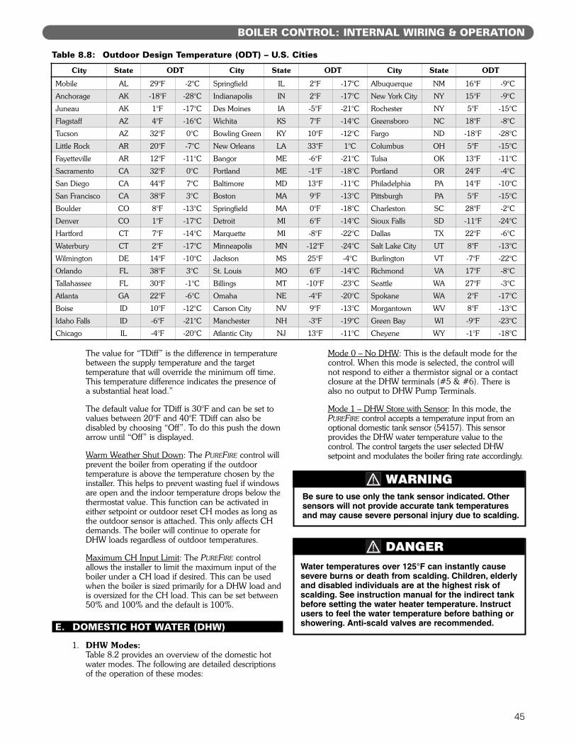
45
The value for “TDiff” is the difference in temperaturebetween the supply temperature and the targettemperature that will override the minimum off time.This temperature difference indicates the presence ofa substantial heat load.”
The default value for TDiff is 30°F and can be set tovalues between 20°F and 40°F. TDiff can also bedisabled by choosing “Off”. To do this push the downarrow until “Off” is displayed.
Warm Weather Shut Down: The PUREFIRE control willprevent the boiler from operating if the outdoortemperature is above the temperature chosen by theinstaller. This helps to prevent wasting fuel if windowsare open and the indoor temperature drops below thethermostat value. This function can be activated ineither setpoint or outdoor reset CH modes as long asthe outdoor sensor is attached. This only affects CHdemands. The boiler will continue to operate forDHW loads regardless of outdoor temperatures.
Maximum CH Input Limit: The PUREFIRE controlallows the installer to limit the maximum input of theboiler under a CH load if desired. This can be usedwhen the boiler is sized primarily for a DHW load andis oversized for the CH load. This can be set between50% and 100% and the default is 100%.
E. DOMESTIC HOT WATER (DHW)
1. DHW Modes:Table 8.2 provides an overview of the domestic hotwater modes. The following are detailed descriptionsof the operation of these modes:
Mode 0 – No DHW: This is the default mode for thecontrol. When this mode is selected, the control willnot respond to either a thermistor signal or a contactclosure at the DHW terminals (#5 & #6). There isalso no output to DHW Pump Terminals.
Mode 1 – DHW Store with Sensor: In this mode, thePUREFIRE control accepts a temperature input from anoptional domestic tank sensor (54157). This sensorprovides the DHW water temperature value to thecontrol. The control targets the user selected DHWsetpoint and modulates the boiler firing rate accordingly.
BOILER CONTROL: INTERNAL WIRING & OPERATION
Table 8.8: Outdoor Design Temperature (ODT) – U.S. Cities
City State ODT City State ODT City State ODT
Mobile AL 29°F -2°C Springfield IL 2°F -17°C Albuquerque NM 16°F -9°C
Anchorage AK -18°F -28°C Indianapolis IN 2°F -17°C New York City NY 15°F -9°C
Juneau AK 1°F -17°C Des Moines IA -5°F -21°C Rochester NY 5°F -15°C
Flagstaff AZ 4°F -16°C Wichita KS 7°F -14°C Greensboro NC 18°F -8°C
Tucson AZ 32°F 0°C Bowling Green KY 10°F -12°C Fargo ND -18°F -28°C
Little Rock AR 20°F -7°C New Orleans LA 33°F 1°C Columbus OH 5°F -15°C
Fayetteville AR 12°F -11°C Bangor ME -6°F -21°C Tulsa OK 13°F -11°C
Sacramento CA 32°F 0°C Portland ME -1°F -18°C Portland OR 24°F -4°C
San Diego CA 44°F 7°C Baltimore MD 13°F -11°C Philadelphia PA 14°F -10°C
San Francisco CA 38°F 3°C Boston MA 9°F -13°C Pittsburgh PA 5°F -15°C
Boulder CO 8°F -13°C Springfield MA 0°F -18°C Charleston SC 28°F -2°C
Denver CO 1°F -17°C Detroit MI 6°F -14°C Sioux Falls SD -11°F -24°C
Hartford CT 7°F -14°C Marquette MI -8°F -22°C Dallas TX 22°F -6°C
Waterbury CT 2°F -17°C Minneapolis MN -12°F -24°C Salt Lake City UT 8°F -13°C
Wilmington DE 14°F -10°C Jackson MS 25°F -4°C Burlington VT -7°F -22°C
Orlando FL 38°F 3°C St. Louis MO 6°F -14°C Richmond VA 17°F -8°C
Tallahassee FL 30°F -1°C Billings MT -10°F -23°C Seattle WA 27°F -3°C
Atlanta GA 22°F -6°C Omaha NE -4°F -20°C Spokane WA 2°F -17°C
Boise ID 10°F -12°C Carson City NV 9°F -13°C Morgantown WV 8°F -13°C
Idaho Falls ID -6°F -21°C Manchester NH -3°F -19°C Green Bay WI -9°F -23°C
Chicago IL -4°F -20°C Atlantic City NJ 13°F -11°C Cheyene WY -1°F -18°C
DANGERWater temperatures over 125°F can instantly causesevere burns or death from scalding. Children, elderlyand disabled individuals are at the highest risk ofscalding. See instruction manual for the indirect tankbefore setting the water heater temperature. Instructusers to feel the water temperature before bathing orshowering. Anti-scald valves are recommended.
Be sure to use only the tank sensor indicated. Othersensors will not provide accurate tank temperaturesand may cause severe personal injury due to scalding.
WARNING
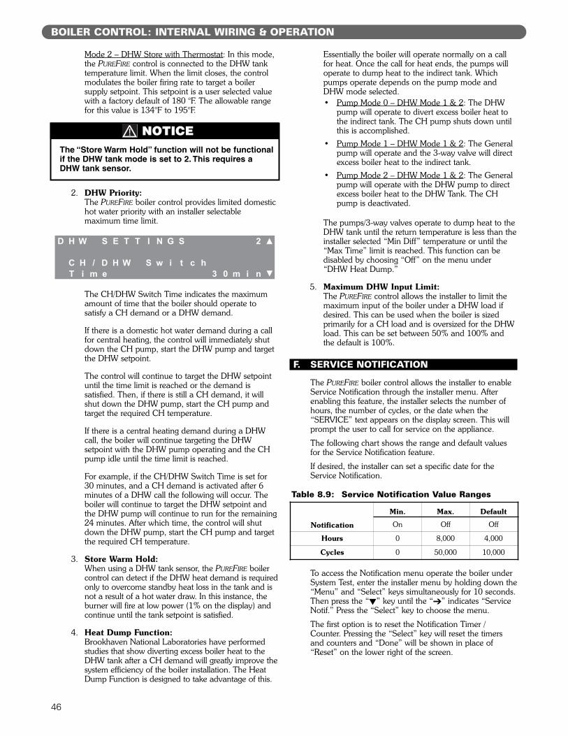
46
Mode 2 – DHW Store with Thermostat: In this mode,the PUREFIRE control is connected to the DHW tanktemperature limit. When the limit closes, the controlmodulates the boiler firing rate to target a boilersupply setpoint. This setpoint is a user selected valuewith a factory default of 180 °F. The allowable rangefor this value is 134°F to 195°F.
2. DHW Priority:The PUREFIRE boiler control provides limited domestichot water priority with an installer selectablemaximum time limit.
The CH/DHW Switch Time indicates the maximumamount of time that the boiler should operate tosatisfy a CH demand or a DHW demand.
If there is a domestic hot water demand during a callfor central heating, the control will immediately shutdown the CH pump, start the DHW pump and targetthe DHW setpoint.
The control will continue to target the DHW setpointuntil the time limit is reached or the demand issatisfied. Then, if there is still a CH demand, it willshut down the DHW pump, start the CH pump andtarget the required CH temperature.
If there is a central heating demand during a DHWcall, the boiler will continue targeting the DHWsetpoint with the DHW pump operating and the CHpump idle until the time limit is reached.
For example, if the CH/DHW Switch Time is set for30 minutes, and a CH demand is activated after 6minutes of a DHW call the following will occur. Theboiler will continue to target the DHW setpoint andthe DHW pump will continue to run for the remaining24 minutes. After which time, the control will shutdown the DHW pump, start the CH pump and targetthe required CH temperature.
3. Store Warm Hold:When using a DHW tank sensor, the PUREFIRE boilercontrol can detect if the DHW heat demand is requiredonly to overcome standby heat loss in the tank and isnot a result of a hot water draw. In this instance, theburner will fire at low power (1% on the display) andcontinue until the tank setpoint is satisfied.
4. Heat Dump Function:Brookhaven National Laboratories have performedstudies that show diverting excess boiler heat to theDHW tank after a CH demand will greatly improve thesystem efficiency of the boiler installation. The HeatDump Function is designed to take advantage of this.
Essentially the boiler will operate normally on a callfor heat. Once the call for heat ends, the pumps willoperate to dump heat to the indirect tank. Whichpumps operate depends on the pump mode andDHW mode selected.• Pump Mode 0 – DHW Mode 1 & 2: The DHW
pump will operate to divert excess boiler heat tothe indirect tank. The CH pump shuts down untilthis is accomplished.
• Pump Mode 1 – DHW Mode 1 & 2: The Generalpump will operate and the 3-way valve will directexcess boiler heat to the indirect tank.
• Pump Mode 2 – DHW Mode 1 & 2: The Generalpump will operate with the DHW pump to directexcess boiler heat to the DHW Tank. The CHpump is deactivated.
The pumps/3-way valves operate to dump heat to theDHW tank until the return temperature is less than theinstaller selected “Min Diff” temperature or until the“Max Time” limit is reached. This function can bedisabled by choosing “Off” on the menu under“DHW Heat Dump.”
5. Maximum DHW Input Limit:The PUREFIRE control allows the installer to limit themaximum input of the boiler under a DHW load ifdesired. This can be used when the boiler is sizedprimarily for a CH load and is oversized for the DHWload. This can be set between 50% and 100% andthe default is 100%.
F. SERVICE NOTIFICATION
The PUREFIRE boiler control allows the installer to enableService Notification through the installer menu. Afterenabling this feature, the installer selects the number ofhours, the number of cycles, or the date when the“SERVICE” text appears on the display screen. This willprompt the user to call for service on the appliance.
The following chart shows the range and default valuesfor the Service Notification feature.
If desired, the installer can set a specific date for theService Notification.
To access the Notification menu operate the boiler underSystem Test, enter the installer menu by holding down the“Menu” and “Select” keys simultaneously for 10 seconds.Then press the “!” key until the “"” indicates “ServiceNotif.” Press the “Select” key to choose the menu.
The first option is to reset the Notification Timer /Counter. Pressing the “Select” key will reset the timersand counters and “Done” will be shown in place of“Reset” on the lower right of the screen.
BOILER CONTROL: INTERNAL WIRING & OPERATION
Table 8.9: Service Notification Value Ranges
Notification
Min. Max. Default
On Off Off
Hours 0 8,000 4,000
Cycles 0 50,000 10,000
The “Store Warm Hold” function will not be functionalif the DHW tank mode is set to 2. This requires aDHW tank sensor.
NOTICE
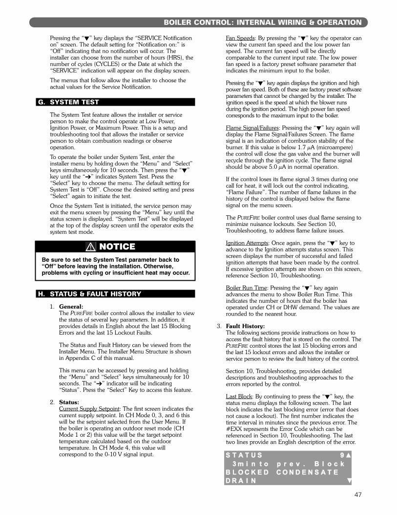
47
Pressing the “!” key displays the “SERVICE Notificationon” screen. The default setting for “Notification on:” is“Off” indicating that no notification will occur. Theinstaller can choose from the number of hours (HRS), thenumber of cycles (CYCLES) or the Date at which the“SERVICE” indication will appear on the display screen.
The menus that follow allow the installer to choose theactual values for the Service Notification.
G. SYSTEM TEST
The System Test feature allows the installer or serviceperson to make the control operate at Low Power,Ignition Power, or Maximum Power. This is a setup andtroubleshooting tool that allows the installer or serviceperson to obtain combustion readings or observeoperation.
To operate the boiler under System Test, enter theinstaller menu by holding down the “Menu” and “Select”keys simultaneously for 10 seconds. Then press the “!”key until the “"” indicates System Test. Press the“Select” key to choose the menu. The default setting forSystem Test is “Off”. Choose the desired setting and press“Select” again to initiate the test.
Once the System Test is initiated, the service person mayexit the menu screen by pressing the “Menu” key until thestatus screen is displayed. “System Test” will be displayedat the top of the display screen until the operator exits thesystem test mode.
H. STATUS & FAULT HISTORY
1. General:The PUREFIRE boiler control allows the installer to viewthe status of several key parameters. In addition, itprovides details in English about the last 15 BlockingErrors and the last 15 Lockout Faults.
The Status and Fault History can be viewed from theInstaller Menu. The Installer Menu Structure is shownin Appendix C of this manual.
This menu can be accessed by pressing and holdingthe “Menu” and “Select” keys simultaneously for 10seconds. The “"” indicator will be indicating“Status”. Press the “Select” Key to access this feature.
2. Status:Current Supply Setpoint: The first screen indicates thecurrent supply setpoint. In CH Mode 0, 3, and 6 thiswill be the setpoint selected from the User Menu. Ifthe boiler is operating an outdoor reset mode (CHMode 1 or 2) this value will be the target setpointtemperature calculated based on the outdoortemperature. In CH Mode 4, this value willcorrespond to the 0-10 V signal input.
Fan Speeds: By pressing the “!” key the operator canview the current fan speed and the low power fanspeed. The current fan speed will be directlycomparable to the current input rate. The low powerfan speed is a factory preset software parameter thatindicates the minimum input to the boiler.
Pressing the “!” key again displays the ignition and highpower fan speed. Both of these are factory preset softwareparameters that cannot be changed by the installer. Theignition speed is the speed at which the blower runsduring the ignition period. The high power fan speedcorresponds to the maximum input to the boiler.
Flame Signal/Failures: Pressing the “!” key again willdisplay the Flame Signal/Failures Screen. The flamesignal is an indication of combustion stability of theburner. If this value is below 1.7 µA (microampere)the control will close the gas valve and the burner willrecycle through the ignition cycle. The flame signalshould be above 5.0 µA in normal operation.
If the control loses its flame signal 3 times during onecall for heat, it will lock out the control indicating,“Flame Failure”. The number of flame failures in thehistory of the control is displayed below the flamesignal on the menu screen.
The PUREFIRE boiler control uses dual flame sensing tominimize nuisance lockouts. See Section 10,Troubleshooting, to address flame failure issues.
Ignition Attempts: Once again, press the “!” key toadvance to the Ignition attempts status screen. Thisscreen displays the number of successful and failedignition attempts that have been made by the control.If excessive ignition attempts are shown on this screen,reference Section 10, Troubleshooting.
Boiler Run Time: Pressing the “!” key againadvances the menu to show Boiler Run Time. Thisindicates the number of hours that the boiler hasoperated under CH or DHW demand. The values arerounded to the nearest hour.
3. Fault History:The following sections provide instructions on how toaccess the fault history that is stored on the control. ThePUREFIRE control stores the last 15 blocking errors andthe last 15 lockout errors and allows the installer orservice person to review the fault history of the control.
Section 10, Troubleshooting, provides detaileddescriptions and troubleshooting approaches to theerrors reported by the control.
Last Block: By continuing to press the “!” key, thestatus menu displays the following screen. The lastblock indicates the last blocking error (error that doesnot cause a lockout). The first number indicates thetime interval in minutes since the previous error. The#EXX represents the Error Code which can bereferenced in Section 10, Troubleshooting. The lasttwo lines provide an English description of the error.
BOILER CONTROL: INTERNAL WIRING & OPERATION
Be sure to set the System Test parameter back to“Off” before leaving the installation. Otherwise,problems with cycling or insufficient heat may occur.
NOTICE
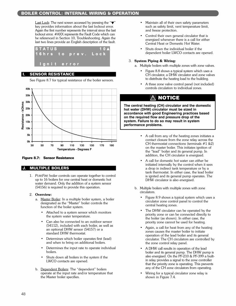
48
Last Lock: The next screen accessed by pressing the “!”key provides information about the last lockout error.Again the first number represents the interval since the lastlockout error. #AXX represents the Fault Code which canbe referenced in Section 10, Troubleshooting. Again thelast two lines provide an English description of the fault.
I. SENSOR RESISTANCESee Figure 8.7 for typical resistance of the boiler sensors.
J. MULTIPLE BOILERS
1. PUREFIRE boiler controls can operate together to controlup to 16 boilers for one central heat or domestic hotwater demand. Only the addition of a system sensor(54156) is required to provide this operation.
2. Overview:a. Master Boiler: In a multiple boiler system, a boiler
designated as the “Master” boiler controls thefunction of the boiler system.• Attached to a system sensor which monitors
the system water temperature.• Can also be connected to an outdoor sensor
(54112), included with each boiler, as well asan optional DHW sensor (54157) or astandard DHW thermostat.
• Determines which boiler operates first (lead)and when to bring on additional boilers.
• Determines the input rate to operate individualboilers.
• Shuts down all boilers in the system if theLWCO contacts are opened.
b. Dependent Boilers: The “dependent” boilersoperate at the input rate and/or temperature thatthe Master boiler specifies.
• Maintain all of their own safety parameterssuch as safety limit, vent temperature limit,and freeze protection.
• Control their own general circulator that isenergized whenever there is a call for eitherCentral Heat or Domestic Hot Water.
• Shuts down the individual boiler if thedependent boiler LWCO contacts are opened.
3. System Piping & Wiring:a. Multiple boilers with multiple zones with zone valves.
• Figure 8.8 shows a typical system which uses aCH circulator, a DHW circulator and zone valvesto distribute the heating load to the building.
• A three zone valve control panel (not included)controls circulation to individual zones.
• A call from any of the heating zones initiates acontact closure from the zone relay across theCH thermostat connections (terminals #1 &2)on the master boiler. This initiates ignition ofthe “lead” boiler and its general pump. Inaddition, the CH circulator is energized.
• A call for domestic hot water can either beinitiated internally by the control when it seesa drop in indirect tank temperature or by atank thermostat. In either case, the lead boileris ignited and its general pump operates. TheDHW circulator is also energized.
b. Multiple boilers with multiple zones with zonecirculators.• Figure 8.9 shows a typical system which uses a
circulator zone control panel to control thecentral heating zones.
• The DHW circulator can be operated by thepriority zone or can be connected directly tothe boiler (as shown). In either case, thepriority zone cannot be used for heating.
• Again, a call for heat from any of the heatingzones causes the master boiler to initiateoperation of the lead boiler and its generalcirculator. The CH circulators are controlled bythe zone control relay panel.
• A DHW call results in operation of the leadboiler and its general pump. The DHW pump isalso energized. On the PF-210 & PF-399 a built-in relay provides a signal to the zone controllerthat the priority zone is operating. This preventsany of the CH zone circulators from operating.
• Wiring for a typical circulator zone relay isshown in Figure 7.4.
BOILER CONTROL: INTERNAL WIRING & OPERATION
The central heating (CH) circulator and the domestichot water (DHW) circulator must be sized inaccordance with good Engineering practices basedon the required flow and pressure drop of thesystem. Failure to do so may result in systemperformance problems.
NOTICE
Figure 8.7: Sensor Resistance
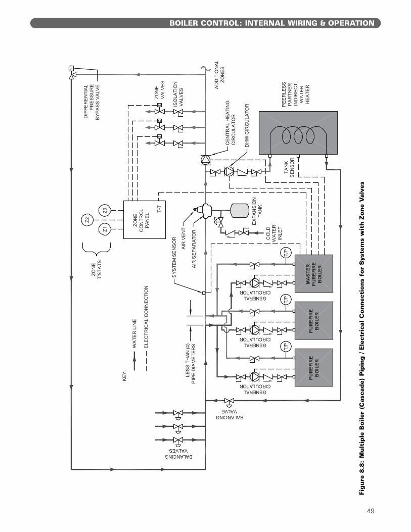
49
BOILER CONTROL: INTERNAL WIRING & OPERATION
Figure
8.8
:M
ult
iple
Boile
r (C
asca
de)
Pip
ing / E
lect
rica
l C
onnec
tions
for
Sys
tem
s w
ith Z
one
Val
ves
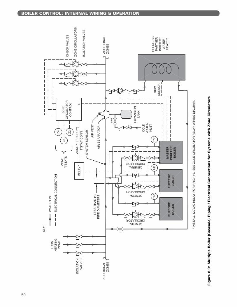
50
BOILER CONTROL: INTERNAL WIRING & OPERATION
Figure
8.9
:M
ult
iple
Boile
r (C
asca
de)
Pip
ing / E
lect
rica
l C
onnec
tions
for
Sys
tem
s w
ith Z
one
Cir
cula
tors
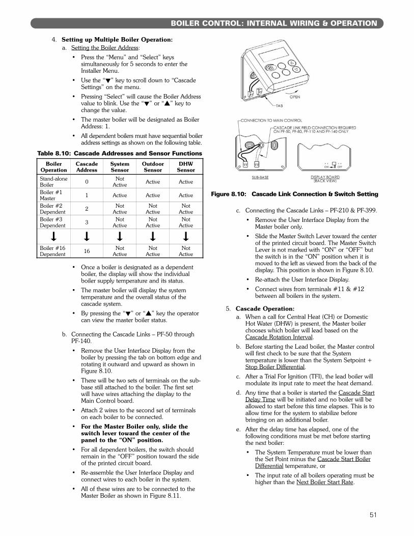
51
BOILER CONTROL: INTERNAL WIRING & OPERATION
4. Setting up Multiple Boiler Operation:a. Setting the Boiler Address:
• Press the “Menu” and “Select” keyssimultaneously for 5 seconds to enter theInstaller Menu.
• Use the “!” key to scroll down to “CascadeSettings” on the menu.
• Pressing “Select” will cause the Boiler Addressvalue to blink. Use the “!” or “#” key tochange the value.
• The master boiler will be designated as BoilerAddress: 1.
• All dependent boilers must have sequential boileraddress settings as shown on the following table.
• Once a boiler is designated as a dependentboiler, the display will show the individualboiler supply temperature and its status.
• The master boiler will display the systemtemperature and the overall status of thecascade system.
• By pressing the “!” or “#” key the operatorcan view the master boiler status.
b. Connecting the Cascade Links – PF-50 throughPF-140.• Remove the User Interface Display from the
boiler by pressing the tab on bottom edge androtating it outward and upward as shown inFigure 8.10.
• There will be two sets of terminals on the sub-base still attached to the boiler. The first setwill have wires attaching the display to theMain Control board.
• Attach 2 wires to the second set of terminalson each boiler to be connected.
• For the Master Boiler only, slide theswitch lever toward the center of thepanel to the “ON” position.
• For all dependent boilers, the switch shouldremain in the “OFF” position toward the sideof the printed circuit board.
• Re-assemble the User Interface Display andconnect wires to each boiler in the system.
• All of these wires are to be connected to theMaster Boiler as shown in Figure 8.11.
c. Connecting the Cascade Links – PF-210 & PF-399.• Remove the User Interface Display from the
Master boiler only.• Slide the Master Switch Lever toward the center
of the printed circuit board. The Master SwitchLever is not marked with “ON” or “OFF” butthe switch is in the “ON” position when it ismoved to the left as viewed from the back of thedisplay. This position is shown in Figure 8.10.
• Re-attach the User Interface Display.• Connect wires from terminals #11 & #12
between all boilers in the system.
5. Cascade Operation:a. When a call for Central Heat (CH) or Domestic
Hot Water (DHW) is present, the Master boilerchooses which boiler will lead based on theCascade Rotation Interval.
b. Before starting the Lead boiler, the Master controlwill first check to be sure that the Systemtemperature is lower than the System Setpoint +Stop Boiler Differential.
c. After a Trial For Ignition (TFI), the lead boiler willmodulate its input rate to meet the heat demand.
d. Any time that a boiler is started the Cascade StartDelay Time will be initiated and no boiler will beallowed to start before this time elapses. This is toallow time for the system to stabilize beforebringing on an additional boiler.
e. After the delay time has elapsed, one of thefollowing conditions must be met before startingthe next boiler:• The System Temperature must be lower than
the Set Point minus the Cascade Start BoilerDifferential temperature, or
• The input rate of all boilers operating must behigher than the Next Boiler Start Rate.
BoilerOperation
CascadeAddress
SystemSensor
OutdoorSensor
DHWSensor
Stand-aloneBoiler 0 Not
Active Active Active
Boiler #1Master 1 Active Active Active
Boiler #2Dependent 2 Not
ActiveNot
ActiveNot
ActiveBoiler #3Dependent 3 Not
ActiveNot
ActiveNot
Active! ! ! ! !Boiler #16Dependent 16 Not
ActiveNot
ActiveNot
Active
Table 8.10: Cascade Addresses and Sensor Functions
Figure 8.10: Cascade Link Connection & Switch Setting
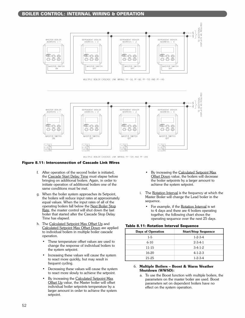
52
BOILER CONTROL: INTERNAL WIRING & OPERATION
f. After operation of the second boiler is initiated,the Cascade Start Delay Time must elapse beforebringing on additional boilers. Again, in order toinitiate operation of additional boilers one of thesame conditions must be met.
g. When the boiler system approaches its Setpoint,the boilers will reduce input rates at approximatelyequal values. When the input rates of all of theoperating boilers fall below the Next Boiler StopRate, the master control will shut down the lastboiler that started after the Cascade Stop DelayTime has elapsed.
h. The Calculated Setpoint Max Offset Up andCalculated Setpoint Max Offset Down are appliedto individual boilers in multiple boiler cascadeoperation.• These temperature offset values are used to
change the response of individual boilers tothe system setpoint.
• Increasing these values will cause the systemto react more quickly, but may result infrequent cycling.
• Decreasing these values will cause the systemto react more slowly to achieve the setpoint.
• By increasing the Calculated Setpoint MaxOffset Up value, the Master boiler will offsetindividual boiler setpoints temperature by alarger amount in order to achieve the systemsetpoint.
• By increasing the Calculated Setpoint MaxOffset Down value, the boilers will decreasethe boiler setpoints by a larger amount toachieve the system setpoint.
i. The Rotation Interval is the frequency at which theMaster Boiler will change the Lead boiler in thesequence.• For example, if the Rotation Interval is set
to 4 days and there are 4 boilers operatingtogether, the following chart shows theoperating sequence over the next 25 days.
6. Multiple Boilers – Boost & Warm WeatherShutdown (WWSD):a. To use the Boost function with multiple boilers, the
parameters on the master boiler are used. Boostparameters set on dependent boilers have noeffect on the system operation.
Table 8.11: Rotation Interval SequenceDays of Operation Start/Stop Sequence
1-5 1-2-3-4
6-10 2-3-4-1
11-15 3-4-1-2
16-20 4-1-2-3
21-25 1-2-3-4
Figure 8.11: Interconnection of Cascade Link Wires
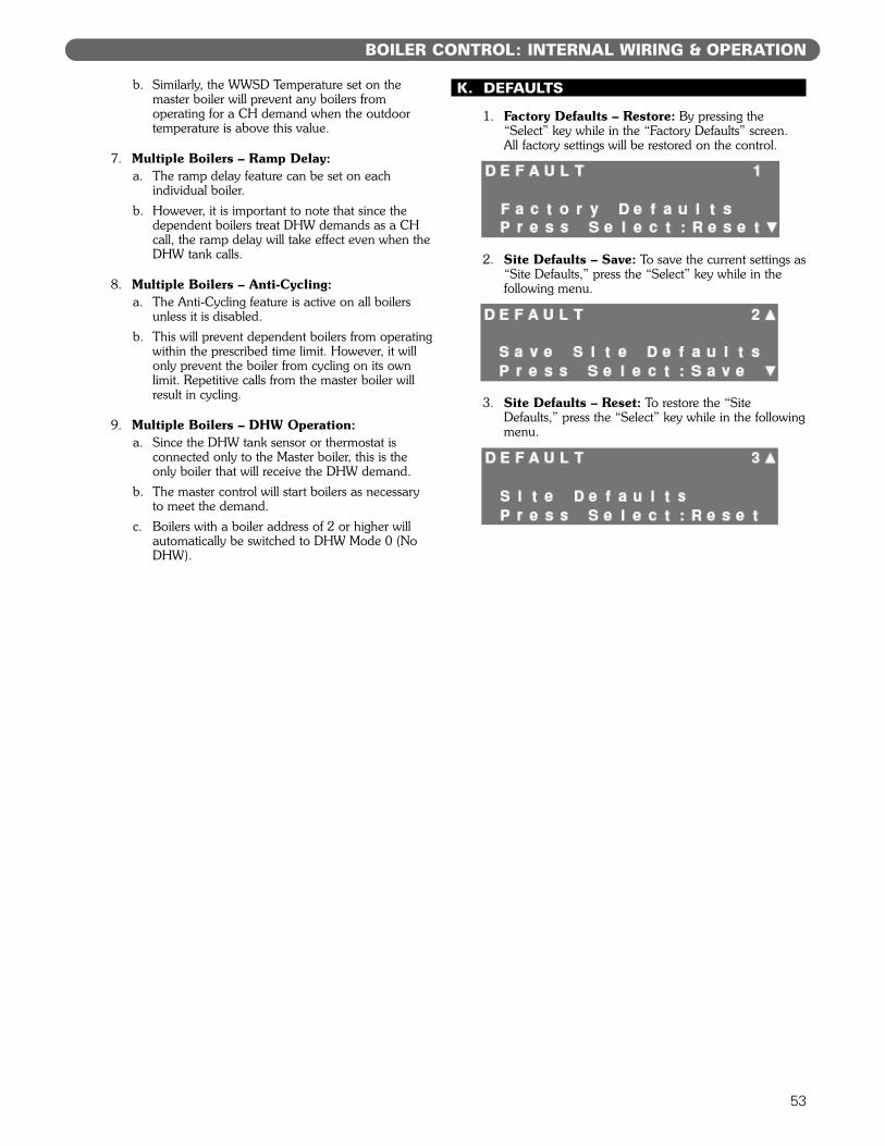
53
b. Similarly, the WWSD Temperature set on themaster boiler will prevent any boilers fromoperating for a CH demand when the outdoortemperature is above this value.
7. Multiple Boilers – Ramp Delay:a. The ramp delay feature can be set on each
individual boiler.b. However, it is important to note that since the
dependent boilers treat DHW demands as a CHcall, the ramp delay will take effect even when theDHW tank calls.
8. Multiple Boilers – Anti-Cycling:a. The Anti-Cycling feature is active on all boilers
unless it is disabled.b. This will prevent dependent boilers from operating
within the prescribed time limit. However, it willonly prevent the boiler from cycling on its ownlimit. Repetitive calls from the master boiler willresult in cycling.
9. Multiple Boilers – DHW Operation:a. Since the DHW tank sensor or thermostat is
connected only to the Master boiler, this is theonly boiler that will receive the DHW demand.
b. The master control will start boilers as necessaryto meet the demand.
c. Boilers with a boiler address of 2 or higher willautomatically be switched to DHW Mode 0 (NoDHW).
K. DEFAULTS
1. Factory Defaults – Restore: By pressing the“Select” key while in the “Factory Defaults” screen. All factory settings will be restored on the control.
2. Site Defaults – Save: To save the current settings as“Site Defaults,” press the “Select” key while in thefollowing menu.
3. Site Defaults – Reset: To restore the “SiteDefaults,” press the “Select” key while in the followingmenu.
BOILER CONTROL: INTERNAL WIRING & OPERATION
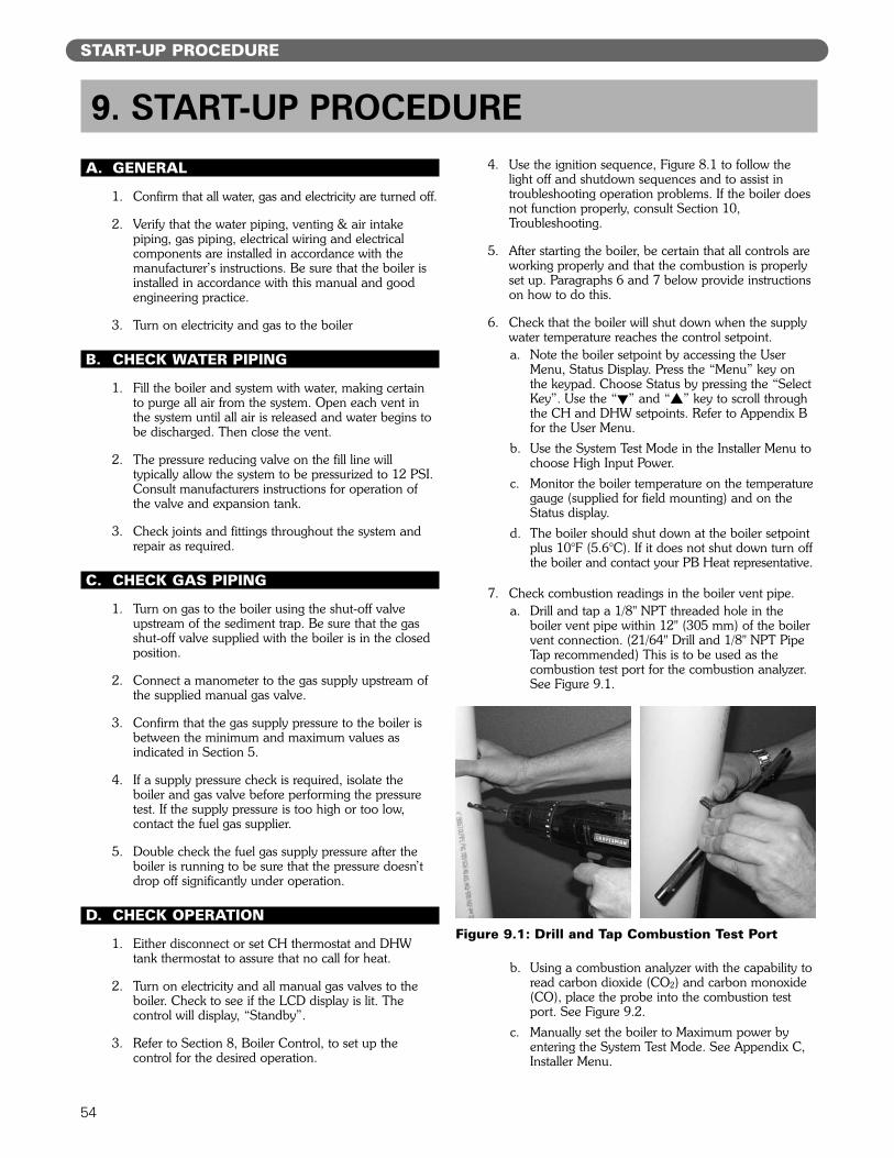
54
A. GENERAL
1. Confirm that all water, gas and electricity are turned off.
2. Verify that the water piping, venting & air intakepiping, gas piping, electrical wiring and electricalcomponents are installed in accordance with themanufacturer’s instructions. Be sure that the boiler isinstalled in accordance with this manual and goodengineering practice.
3. Turn on electricity and gas to the boiler
B. CHECK WATER PIPING
1. Fill the boiler and system with water, making certainto purge all air from the system. Open each vent inthe system until all air is released and water begins tobe discharged. Then close the vent.
2. The pressure reducing valve on the fill line willtypically allow the system to be pressurized to 12 PSI.Consult manufacturers instructions for operation ofthe valve and expansion tank.
3. Check joints and fittings throughout the system andrepair as required.
C. CHECK GAS PIPING
1. Turn on gas to the boiler using the shut-off valveupstream of the sediment trap. Be sure that the gasshut-off valve supplied with the boiler is in the closedposition.
2. Connect a manometer to the gas supply upstream ofthe supplied manual gas valve.
3. Confirm that the gas supply pressure to the boiler isbetween the minimum and maximum values asindicated in Section 5.
4. If a supply pressure check is required, isolate theboiler and gas valve before performing the pressuretest. If the supply pressure is too high or too low,contact the fuel gas supplier.
5. Double check the fuel gas supply pressure after theboiler is running to be sure that the pressure doesn’tdrop off significantly under operation.
D. CHECK OPERATION
1. Either disconnect or set CH thermostat and DHWtank thermostat to assure that no call for heat.
2. Turn on electricity and all manual gas valves to theboiler. Check to see if the LCD display is lit. Thecontrol will display, “Standby”.
3. Refer to Section 8, Boiler Control, to set up thecontrol for the desired operation.
4. Use the ignition sequence, Figure 8.1 to follow thelight off and shutdown sequences and to assist introubleshooting operation problems. If the boiler doesnot function properly, consult Section 10,Troubleshooting.
5. After starting the boiler, be certain that all controls areworking properly and that the combustion is properlyset up. Paragraphs 6 and 7 below provide instructionson how to do this.
6. Check that the boiler will shut down when the supplywater temperature reaches the control setpoint.a. Note the boiler setpoint by accessing the User
Menu, Status Display. Press the “Menu” key onthe keypad. Choose Status by pressing the “SelectKey”. Use the “!” and “#” key to scroll throughthe CH and DHW setpoints. Refer to Appendix Bfor the User Menu.
b. Use the System Test Mode in the Installer Menu tochoose High Input Power.
c. Monitor the boiler temperature on the temperaturegauge (supplied for field mounting) and on theStatus display.
d. The boiler should shut down at the boiler setpointplus 10°F (5.6°C). If it does not shut down turn offthe boiler and contact your PB Heat representative.
7. Check combustion readings in the boiler vent pipe.a. Drill and tap a 1/8" NPT threaded hole in the
boiler vent pipe within 12" (305 mm) of the boilervent connection. (21/64" Drill and 1/8" NPT PipeTap recommended) This is to be used as thecombustion test port for the combustion analyzer.See Figure 9.1.
b. Using a combustion analyzer with the capability toread carbon dioxide (CO2) and carbon monoxide(CO), place the probe into the combustion testport. See Figure 9.2.
c. Manually set the boiler to Maximum power byentering the System Test Mode. See Appendix C,Installer Menu.
9. START-UP PROCEDURE
Figure 9.1: Drill and Tap Combustion Test Port
START-UP PROCEDURE
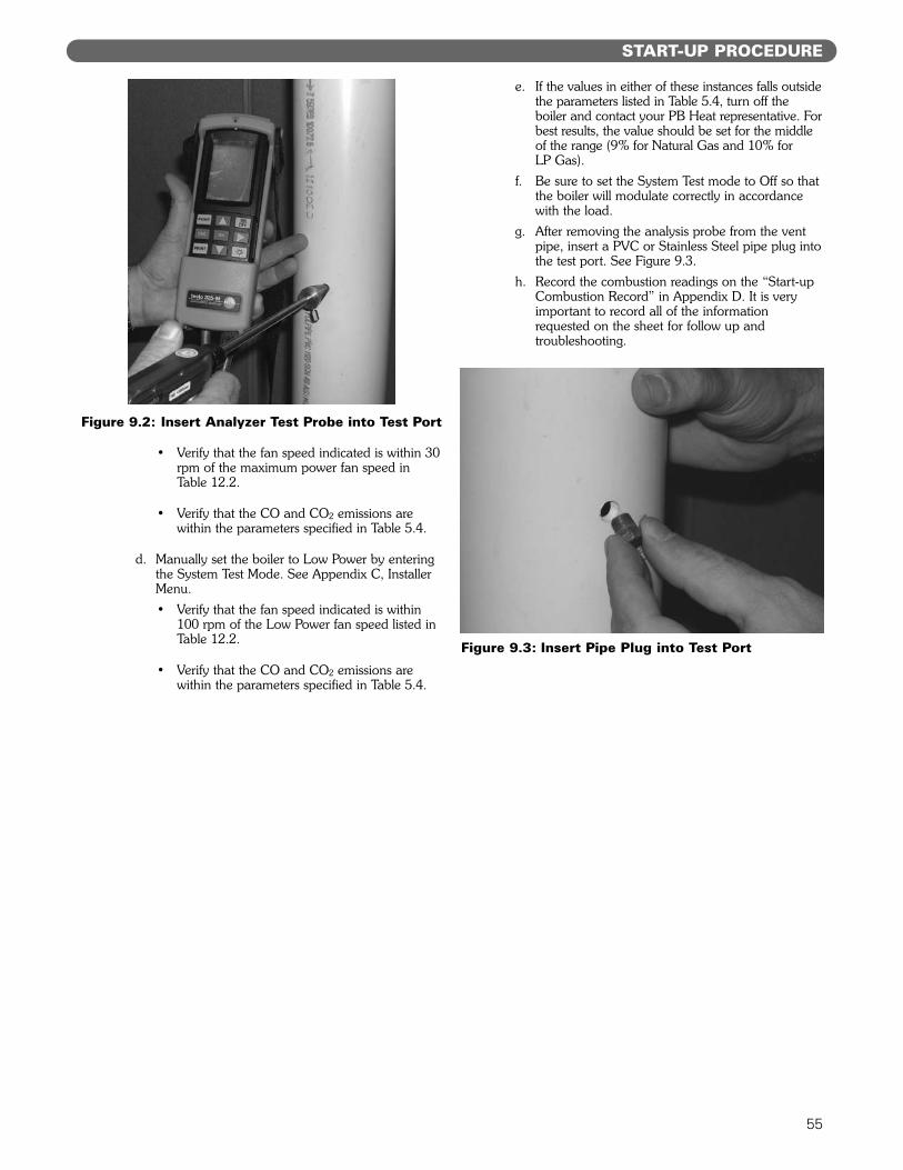
55
• Verify that the fan speed indicated is within 30rpm of the maximum power fan speed inTable 12.2.
• Verify that the CO and CO2 emissions arewithin the parameters specified in Table 5.4.
d. Manually set the boiler to Low Power by enteringthe System Test Mode. See Appendix C, InstallerMenu.• Verify that the fan speed indicated is within
100 rpm of the Low Power fan speed listed inTable 12.2.
• Verify that the CO and CO2 emissions arewithin the parameters specified in Table 5.4.
e. If the values in either of these instances falls outsidethe parameters listed in Table 5.4, turn off theboiler and contact your PB Heat representative. Forbest results, the value should be set for the middleof the range (9% for Natural Gas and 10% for LP Gas).
f. Be sure to set the System Test mode to Off so thatthe boiler will modulate correctly in accordancewith the load.
g. After removing the analysis probe from the ventpipe, insert a PVC or Stainless Steel pipe plug intothe test port. See Figure 9.3.
h. Record the combustion readings on the “Start-upCombustion Record” in Appendix D. It is veryimportant to record all of the informationrequested on the sheet for follow up andtroubleshooting.
START-UP PROCEDURE
Figure 9.2: Insert Analyzer Test Probe into Test Port
Figure 9.3: Insert Pipe Plug into Test Port
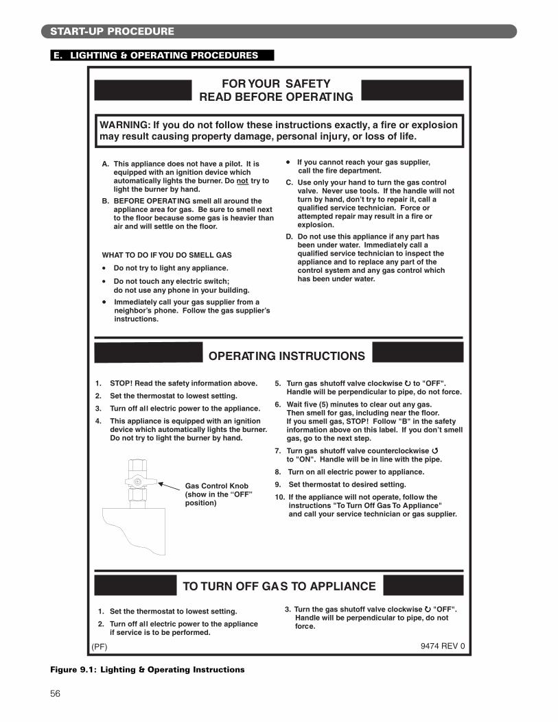
E. LIGHTING & OPERATING PROCEDURES
56
START-UP PROCEDURE
FOR YOUR SAFETY
READ BEFORE OPERATING
OPERATING INSTRUCTIONS
1. STOP! Read the safety information above.
2. Set the thermostat to lowest setting.
3. Turn off all electric power to the appliance.
4. This appliance is equipped with an ignition device which automatically lights the burner. Do not try to light the burner by hand.
5. Turn gas shutoff valve clockwise to "OFF". Handle will be perpendicular to pipe, do not force.
6. Wait five (5) minutes to clear out any gas. Then smell for gas, including near the floor. If you smell gas, STOP! Follow "B" in the safety information above on this label. If you don’t smell gas, go to the next step.
7. Turn gas shutoff valve counterclockwise to "ON". Handle will be in line with the pipe.
8. Turn on all electric power to appliance.
9. Set thermostat to desired setting.
10. If the appliance will not operate, follow the instructions "To Turn Off Gas To Appliance" and call your service technician or gas supplier.
TO TURN OFF GAS TO APPLIANCE
Gas Control Knob (show in the “OFF” position)
A. This appliance does not have a pilot. It is equipped with an ignition device which automatically lights the burner. Do not try to light the burner by hand.
B. BEFORE OPERATING smell all around the appliance area for gas. Be sure to smell next to the floor because some gas is heavier than air and will settle on the floor.
WHAT TO DO IF YOU DO SMELL GAS
• Do not try to light any appliance.
• Do not touch any electric switch; do not use any phone in your building.
Immediately call your gas supplier from a neighbor’s phone. Follow the gas supplier’s instructions.
If you cannot reach your gas supplier, call the fire department.
C. Use only your hand to turn the gas control valve. Never use tools. If the handle will not turn by hand, don’t try to repair it, call a qualified service technician. Force or attempted repair may result in a fire or explosion.
D. Do not use this appliance if any part has been under water. Immediately call a qualified service technician to inspect the appliance and to replace any part of the control system and any gas control which has been under water.
1. Set the thermostat to lowest setting.
2. Turn off all electric power to the appliance if service is to be performed.
3. Turn the gas shutoff valve clockwise "OFF". Handle will be perpendicular to pipe, do not force.
9474 REV 0
WARNING: If you do not follow these instructions exactly, a fire or explosion may result causing property damage, personal injury, or loss of life.
(PF)
Figure 9.1: Lighting & Operating Instructions
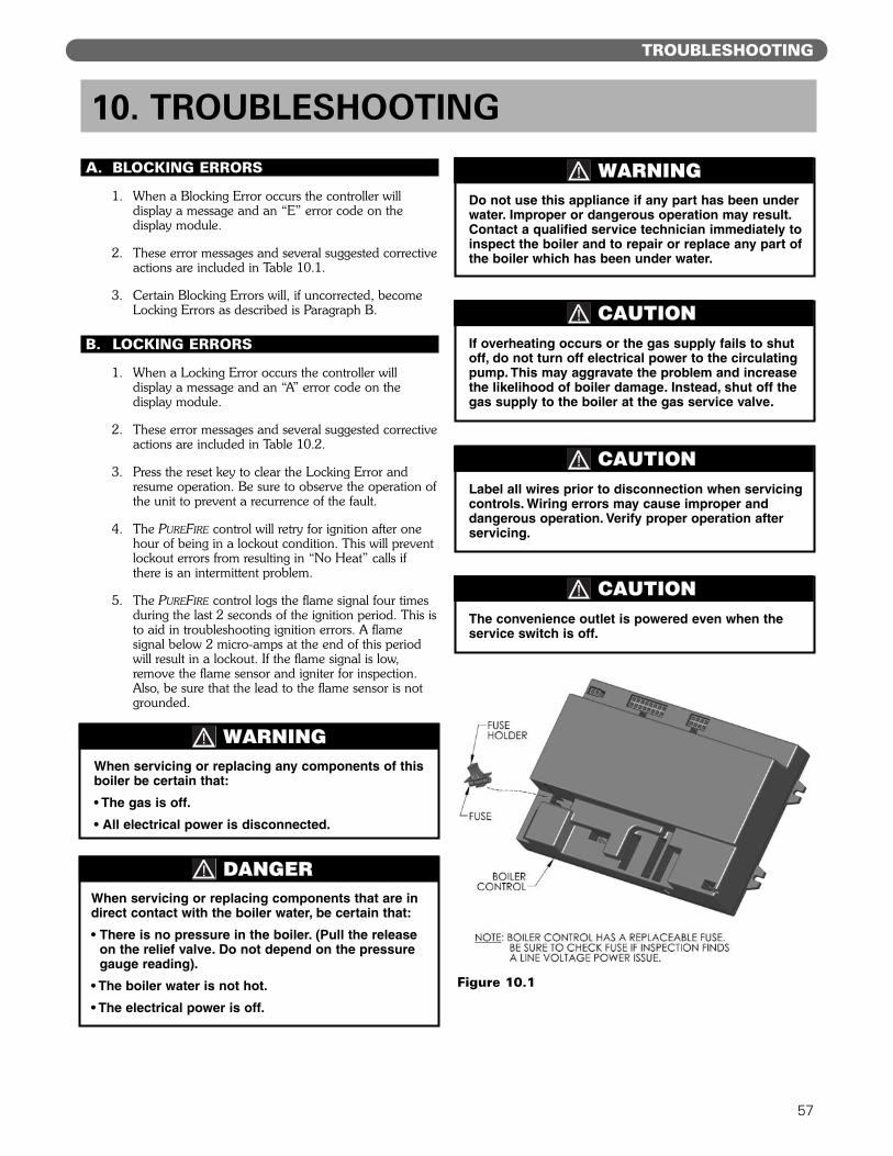
57
TROUBLESHOOTING
A. BLOCKING ERRORS
1. When a Blocking Error occurs the controller willdisplay a message and an “E” error code on thedisplay module.
2. These error messages and several suggested correctiveactions are included in Table 10.1.
3. Certain Blocking Errors will, if uncorrected, becomeLocking Errors as described is Paragraph B.
B. LOCKING ERRORS
1. When a Locking Error occurs the controller willdisplay a message and an “A” error code on thedisplay module.
2. These error messages and several suggested correctiveactions are included in Table 10.2.
3. Press the reset key to clear the Locking Error andresume operation. Be sure to observe the operation ofthe unit to prevent a recurrence of the fault.
4. The PUREFIRE control will retry for ignition after onehour of being in a lockout condition. This will preventlockout errors from resulting in “No Heat” calls ifthere is an intermittent problem.
5. The PUREFIRE control logs the flame signal four timesduring the last 2 seconds of the ignition period. This isto aid in troubleshooting ignition errors. A flamesignal below 2 micro-amps at the end of this periodwill result in a lockout. If the flame signal is low,remove the flame sensor and igniter for inspection.Also, be sure that the lead to the flame sensor is notgrounded.
10. TROUBLESHOOTING
If overheating occurs or the gas supply fails to shutoff, do not turn off electrical power to the circulatingpump. This may aggravate the problem and increasethe likelihood of boiler damage. Instead, shut off thegas supply to the boiler at the gas service valve.
CAUTION
DANGERWhen servicing or replacing components that are indirect contact with the boiler water, be certain that:
• There is no pressure in the boiler. (Pull the releaseon the relief valve. Do not depend on the pressuregauge reading).
• The boiler water is not hot.
• The electrical power is off.
When servicing or replacing any components of thisboiler be certain that:
• The gas is off.
• All electrical power is disconnected.
WARNING
Do not use this appliance if any part has been underwater. Improper or dangerous operation may result.Contact a qualified service technician immediately toinspect the boiler and to repair or replace any part ofthe boiler which has been under water.
WARNING
Label all wires prior to disconnection when servicingcontrols. Wiring errors may cause improper anddangerous operation. Verify proper operation afterservicing.
CAUTION
The convenience outlet is powered even when theservice switch is off.
CAUTION
Figure 10.1
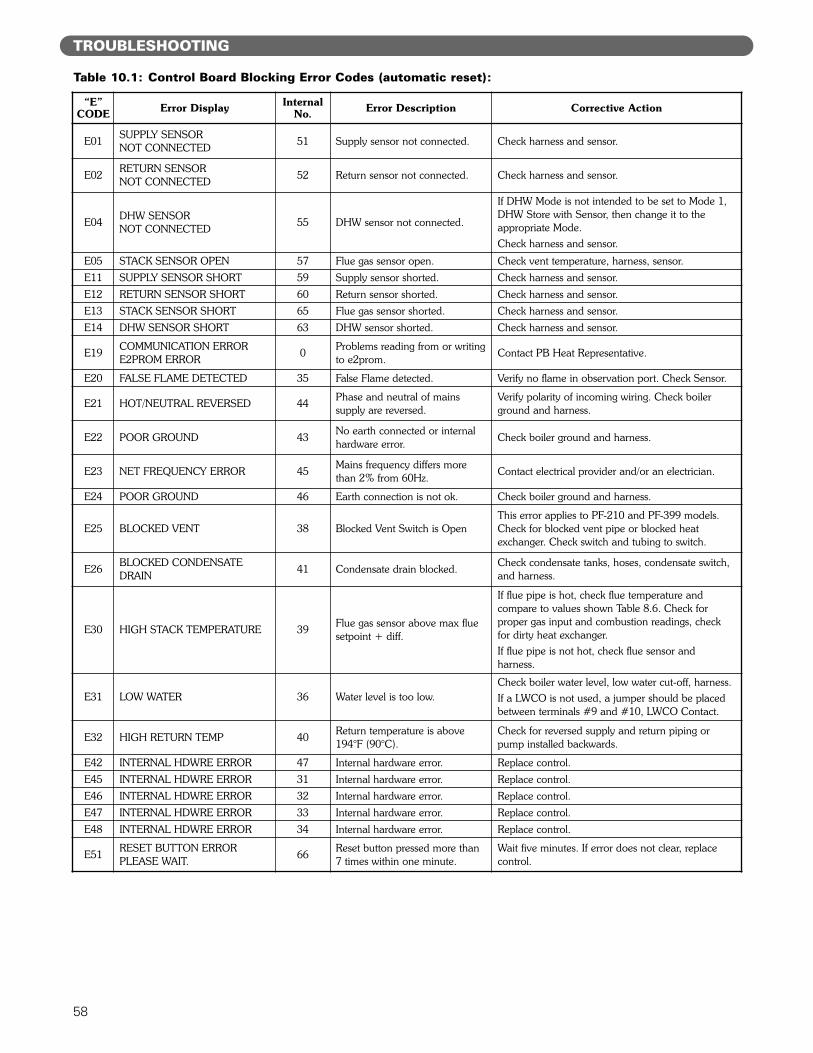
58
TROUBLESHOOTING
Table 10.1: Control Board Blocking Error Codes (automatic reset):
“E”CODE Error Display Internal
No. Error Description Corrective Action
E01 SUPPLY SENSORNOT CONNECTED 51 Supply sensor not connected. Check harness and sensor.
E02 RETURN SENSORNOT CONNECTED 52 Return sensor not connected. Check harness and sensor.
E04 DHW SENSORNOT CONNECTED 55 DHW sensor not connected.
If DHW Mode is not intended to be set to Mode 1,DHW Store with Sensor, then change it to theappropriate Mode.Check harness and sensor.
E05 STACK SENSOR OPEN 57 Flue gas sensor open. Check vent temperature, harness, sensor.E11 SUPPLY SENSOR SHORT 59 Supply sensor shorted. Check harness and sensor.E12 RETURN SENSOR SHORT 60 Return sensor shorted. Check harness and sensor.E13 STACK SENSOR SHORT 65 Flue gas sensor shorted. Check harness and sensor.E14 DHW SENSOR SHORT 63 DHW sensor shorted. Check harness and sensor.
E19 COMMUNICATION ERRORE2PROM ERROR 0 Problems reading from or writing
to e2prom. Contact PB Heat Representative.
E20 FALSE FLAME DETECTED 35 False Flame detected. Verify no flame in observation port. Check Sensor.
E21 HOT/NEUTRAL REVERSED 44 Phase and neutral of mains supply are reversed.
Verify polarity of incoming wiring. Check boilerground and harness.
E22 POOR GROUND 43 No earth connected or internalhardware error. Check boiler ground and harness.
E23 NET FREQUENCY ERROR 45 Mains frequency differs morethan 2% from 60Hz. Contact electrical provider and/or an electrician.
E24 POOR GROUND 46 Earth connection is not ok. Check boiler ground and harness.
E25 BLOCKED VENT 38 Blocked Vent Switch is OpenThis error applies to PF-210 and PF-399 models.Check for blocked vent pipe or blocked heatexchanger. Check switch and tubing to switch.
E26 BLOCKED CONDENSATEDRAIN 41 Condensate drain blocked. Check condensate tanks, hoses, condensate switch,
and harness.
E30 HIGH STACK TEMPERATURE 39 Flue gas sensor above max fluesetpoint + diff.
If flue pipe is hot, check flue temperature and compare to values shown Table 8.6. Check forproper gas input and combustion readings, checkfor dirty heat exchanger.If flue pipe is not hot, check flue sensor and harness.
E31 LOW WATER 36 Water level is too low.Check boiler water level, low water cut-off, harness.If a LWCO is not used, a jumper should be placedbetween terminals #9 and #10, LWCO Contact.
E32 HIGH RETURN TEMP 40 Return temperature is above194°F (90°C).
Check for reversed supply and return piping orpump installed backwards.
E42 INTERNAL HDWRE ERROR 47 Internal hardware error. Replace control.E45 INTERNAL HDWRE ERROR 31 Internal hardware error. Replace control.E46 INTERNAL HDWRE ERROR 32 Internal hardware error. Replace control.E47 INTERNAL HDWRE ERROR 33 Internal hardware error. Replace control.E48 INTERNAL HDWRE ERROR 34 Internal hardware error. Replace control.
E51 RESET BUTTON ERRORPLEASE WAIT. 66 Reset button pressed more than
7 times within one minute.Wait five minutes. If error does not clear, replacecontrol.
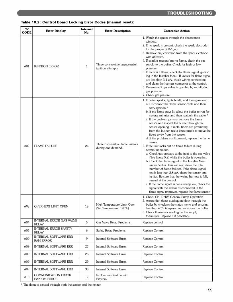
59
TROUBLESHOOTING
Table 10.2: Control Board Locking Error Codes (manual reset):
“A”CODE Error Display Internal
No. Error Description Corrective Action
A01 IGNITION ERROR 1 Three consecutive unsuccessfulignition attempts.
1. Watch the igniter through the observation window.
2. If no spark is present, check the spark electrodefor the proper 3/16" gap.
3. Remove any corrosion from the spark electrodewith abrasive.
4. If spark is present but no flame, check the gassupply to the boiler. Check for high or low pressure.
5. If there is a flame, check the flame signal ignitionlog in the Installer Menu. If values for flame signalare less than 3.1 µA, check wiring connectionsand clean the harness connector at the control.
6. Determine if gas valve is opening by monitoringgas pressure.
7. Check gas presure.
A02 FLAME FAILURE 24 Three consecutive flame failuresduring one demand.
1. If boiler sparks, lights briefly and then goes out:a. Disconnect the flame sensor cable and then
retry ignition.*b. If the flame stays lit, allow the boiler to run for
several minutes and then reattach the cable.*c. If the problem persists, remove the flame
sensor and inspect the burner through the sensor opening. If metal fibers are protrudingfrom the burner, use a blunt probe to move thefibers away from the sensor.
d. If the problem is still present, replace the flamesensor.
2. If the unit locks out on flame failure during normal operation:a. Check gas pressure at the inlet to the gas valve
(See figure 5.2) while the boiler is operating.b. Check the flame signal in the Installer Menu
under Status. This will also show the totalnumber of flame failures. If the flame signalreads less than 2.8 µA, clean the sensor andigniter. Be sure that the wiring harness is fullyseated at the control.
c. If the flame signal is consistently low, check thesignal with the sensor disconnected. If theflame signal improves, replace the flame sensor.
A03 OVERHEAT LIMIT OPEN 18 High Temperature Limit Open (Set Temperature: 195°F)
1. Check CH, DHW, General Pump Operation2. Assure that there is adequate flow through the
boiler by checking the status menu and assuringless than 40°F temperature rise across the boiler.
3. Check thermistor reading on the supply thermistor. Replace it if necessary.
A04 INTERNAL ERROR GAS VALVERELAY 5 Gas Valve Relay Problems. Replace control
A05 INTERNAL ERROR SAFETYRELAY 6 Safety Relay Problems. Replace Control
A09 INTERNAL SOFTWARE ERRRAM ERROR 9 Internal Software Error. Replace Control
A09 INTERNAL SOFTWARE ERR 27 Internal Software Error. Replace Control
A09 INTERNAL SOFTWARE ERR 28 Internal Software Error. Replace Control
A09 INTERNAL SOFTWARE ERR 29 Internal Software Error. Replace Control
A09 INTERNAL SOFTWARE ERR 30 Internal Software Error. Replace Control
A10 COMMUNICATION ERRORE2PROM ERROR 12 No Communication with
E2prom. Replace Control
* The flame is sensed through both the sensor and the igniter.
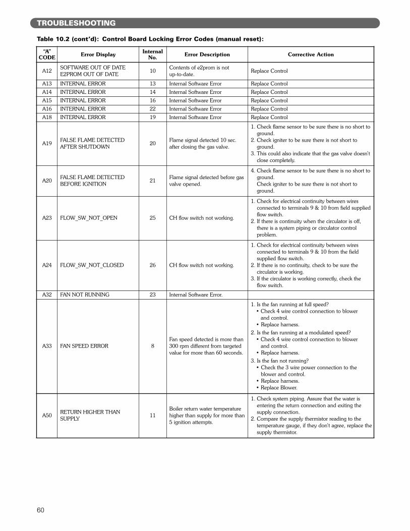
60
TROUBLESHOOTING
“A”CODE Error Display Internal
No. Error Description Corrective Action
A12 SOFTWARE OUT OF DATEE2PROM OUT OF DATE 10 Contents of e2prom is not
up-to-date. Replace Control
A13 INTERNAL ERROR 13 Internal Software Error Replace ControlA14 INTERNAL ERROR 14 Internal Software Error Replace ControlA15 INTERNAL ERROR 16 Internal Software Error Replace ControlA16 INTERNAL ERROR 22 Internal Software Error Replace ControlA18 INTERNAL ERROR 19 Internal Software Error Replace Control
A19 FALSE FLAME DETECTEDAFTER SHUTDOWN 20 Flame signal detected 10 sec.
after closing the gas valve.
1. Check flame sensor to be sure there is no short toground.
2. Check igniter to be sure there is not short toground.
3. This could also indicate that the gas valve doesn’tclose completely.
A20 FALSE FLAME DETECTEDBEFORE IGNITION 21 Flame signal detected before gas
valve opened.
4. Check flame sensor to be sure there is no short toground.Check igniter to be sure there is not short toground.
A23 FLOW_SW_NOT_OPEN 25 CH flow switch not working.
1. Check for electrical continuity between wires connected to terminals 9 & 10 from field suppliedflow switch.
2. If there is continuity when the circulator is off,there is a system piping or circulator control problem.
A24 FLOW_SW_NOT_CLOSED 26 CH flow switch not working.
1. Check for electrical continuity between wires connected to terminals 9 & 10 from the field supplied flow switch.
2. If there is no continuity, check to be sure the circulator is working.
3. If the circulator is working correctly, check the flow switch.
A32 FAN NOT RUNNING 23 Internal Software Error.
A33 FAN SPEED ERROR 8Fan speed detected is more than300 rpm different from targetedvalue for more than 60 seconds.
1. Is the fan running at full speed?• Check 4 wire control connection to blower
and control.• Replace harness.
2. Is the fan running at a modulated speed?• Check 4 wire control connection to blower
and control.• Replace harness.
3. Is the fan not running?• Check the 3 wire power connection to the
blower and control.• Replace harness.• Replace Blower.
A50 RETURN HIGHER THAN SUPPLY 11
Boiler return water temperaturehigher than supply for more than5 ignition attempts.
1. Check system piping. Assure that the water isentering the return connection and exiting thesupply connection.
2. Compare the supply thermistor reading to the temperature gauge, if they don’t agree, replace thesupply thermistor.
Table 10.2 (cont’d): Control Board Locking Error Codes (manual reset):
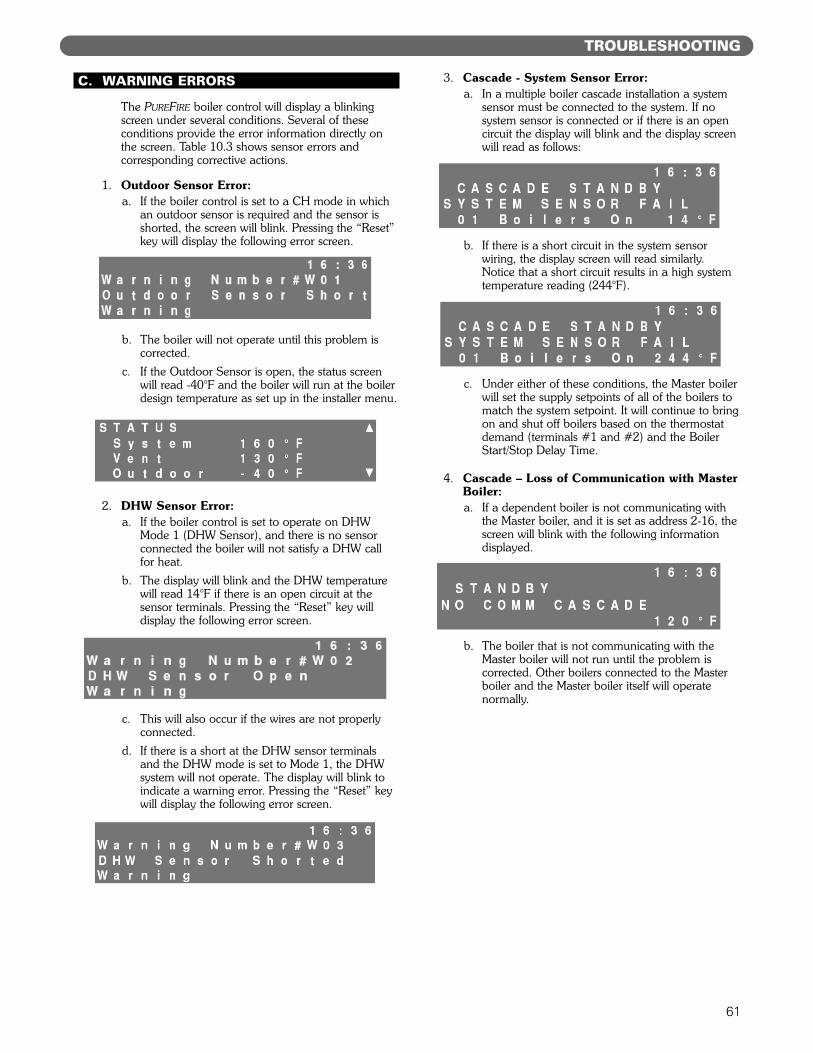
61
C. WARNING ERRORS
The PUREFIRE boiler control will display a blinkingscreen under several conditions. Several of theseconditions provide the error information directly onthe screen. Table 10.3 shows sensor errors andcorresponding corrective actions.
1. Outdoor Sensor Error:a. If the boiler control is set to a CH mode in which
an outdoor sensor is required and the sensor isshorted, the screen will blink. Pressing the “Reset”key will display the following error screen.
b. The boiler will not operate until this problem iscorrected.
c. If the Outdoor Sensor is open, the status screenwill read -40°F and the boiler will run at the boilerdesign temperature as set up in the installer menu.
2. DHW Sensor Error:a. If the boiler control is set to operate on DHW
Mode 1 (DHW Sensor), and there is no sensorconnected the boiler will not satisfy a DHW callfor heat.
b. The display will blink and the DHW temperaturewill read 14°F if there is an open circuit at thesensor terminals. Pressing the “Reset” key willdisplay the following error screen.
c. This will also occur if the wires are not properlyconnected.
d. If there is a short at the DHW sensor terminalsand the DHW mode is set to Mode 1, the DHWsystem will not operate. The display will blink toindicate a warning error. Pressing the “Reset” keywill display the following error screen.
3. Cascade - System Sensor Error:a. In a multiple boiler cascade installation a system
sensor must be connected to the system. If nosystem sensor is connected or if there is an opencircuit the display will blink and the display screenwill read as follows:
b. If there is a short circuit in the system sensorwiring, the display screen will read similarly.Notice that a short circuit results in a high systemtemperature reading (244°F).
c. Under either of these conditions, the Master boilerwill set the supply setpoints of all of the boilers tomatch the system setpoint. It will continue to bringon and shut off boilers based on the thermostatdemand (terminals #1 and #2) and the BoilerStart/Stop Delay Time.
4. Cascade – Loss of Communication with MasterBoiler:a. If a dependent boiler is not communicating with
the Master boiler, and it is set as address 2-16, thescreen will blink with the following informationdisplayed.
b. The boiler that is not communicating with theMaster boiler will not run until the problem iscorrected. Other boilers connected to the Masterboiler and the Master boiler itself will operatenormally.
TROUBLESHOOTING
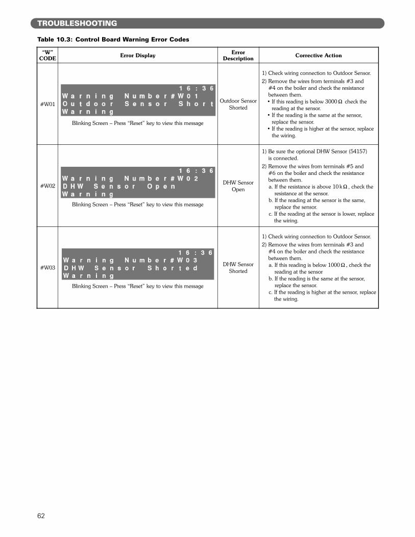
62
TROUBLESHOOTING
Table 10.3: Control Board Warning Error Codes
“W”CODE Error Display Error
Description Corrective Action
#W01
Blinking Screen – Press “Reset” key to view this message
Outdoor SensorShorted
1) Check wiring connection to Outdoor Sensor.2) Remove the wires from terminals #3 and
#4 on the boiler and check the resistancebetween them.• If this reading is below 3000" check the
reading at the sensor.• If the reading is the same at the sensor,
replace the sensor.• If the reading is higher at the sensor, replace
the wiring.
#W02
Blinking Screen – Press “Reset” key to view this message
DHW SensorOpen
1) Be sure the optional DHW Sensor (54157) is connected.
2) Remove the wires from terminals #5 and #6 on the boiler and check the resistancebetween them.a. If the resistance is above 10 k", check the
resistance at the sensor.b. If the reading at the sensor is the same,
replace the sensor.c. If the reading at the sensor is lower, replace
the wiring.
#W03
Blinking Screen – Press “Reset” key to view this message
DHW SensorShorted
1) Check wiring connection to Outdoor Sensor.2) Remove the wires from terminals #3 and
#4 on the boiler and check the resistancebetween them.a. If this reading is below 1000"# check the
reading at the sensorb. If the reading is the same at the sensor,
replace the sensor.c. If the reading is higher at the sensor, replace
the wiring.
63
MAINTENANCE
11. MAINTENANCE
WARNING
Product Safety InformationRefractory Ceramic Fiber Product
This appliance contains materials made from refractory ceramic fibers (RCF). Airborne RCFfibers, when inhaled, have been classified by the International Agency for Research onCancer (IARC), as a possible carcinogen to humans. After the RCF materials have beenexposed to temperatures above 1800°F, they can change into crystalline silica, which hasbeen classified by the IARC as carcinogenic to humans. If particles become airborne duringservice or repair, inhalation of these particles may be hazardous to your health.
Avoid Breathing Fiber Particulates and Dust
Suppliers of RCF recommend the following precautions be taken when handling these mate-rials:
Precautionary Measures:Provide adequate ventilation.Wear a NIOSH/MSHA approved respirator.Wear long sleeved, loose fitting clothing and gloves to prevent skin contact.Wear eye goggles.Minimize airborne dust prior to handling and removal by water misting the material andavoiding unnecessary disturbance of materials. Wash work clothes separately from others. Rinse washer thoroughly after use.Discard RCF materials by sealing in an airtight plastic bag.
First Aid Procedures:Inhalation: If breathing difficulty or irritation occurs, move to a location with fresh clean air.Seek immediate medical attention if symptoms persist.Skin Contact: Wash affected area gently with a mild soap and warm water. Seek immediatemedical attention if irritation persists.Eye Contact: Flush eyes with water for 15 minutes while holding eyelids apart. Do not rubeyes. Seek immediate medical attention if irritation persists.Ingestion: Drink 1 to 2 glasses of water. Do not induce vomiting. Seek immediate medicalattention.
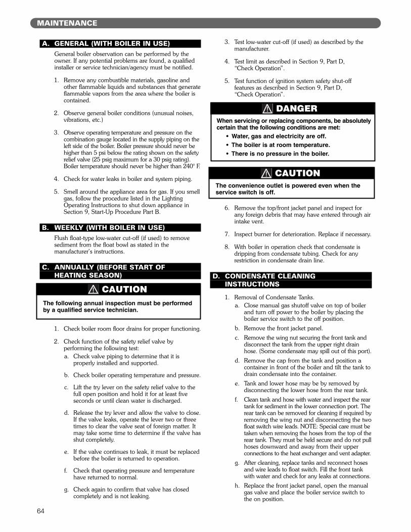
64
MAINTENANCE
A. GENERAL (WITH BOILER IN USE)General boiler observation can be performed by theowner. If any potential problems are found, a qualifiedinstaller or service technician/agency must be notified.
1. Remove any combustible materials, gasoline andother flammable liquids and substances that generateflammable vapors from the area where the boiler iscontained.
2. Observe general boiler conditions (unusual noises,vibrations, etc.)
3. Observe operating temperature and pressure on thecombination gauge located in the supply piping on theleft side of the boiler. Boiler pressure should never behigher than 5 psi below the rating shown on the safetyrelief valve (25 psig maximum for a 30 psig rating).Boiler temperature should never be higher than 240° F.
4. Check for water leaks in boiler and system piping.
5. Smell around the appliance area for gas. If you smellgas, follow the procedure listed in the LightingOperating Instructions to shut down appliance inSection 9, Start-Up Procedure Part B.
B. WEEKLY (WITH BOILER IN USE)Flush float-type low-water cut-off (if used) to removesediment from the float bowl as stated in themanufacturer’s instructions.
C. ANNUALLY (BEFORE START OFHEATING SEASON)
1. Check boiler room floor drains for proper functioning.
2. Check function of the safety relief valve byperforming the following test:a. Check valve piping to determine that it is
properly installed and supported.
b. Check boiler operating temperature and pressure.
c. Lift the try lever on the safety relief valve to thefull open position and hold it for at least fiveseconds or until clean water is discharged.
d. Release the try lever and allow the valve to close.If the valve leaks, operate the lever two or threetimes to clear the valve seat of foreign matter. Itmay take some time to determine if the valve hasshut completely.
e. If the valve continues to leak, it must be replacedbefore the boiler is returned to operation.
f. Check that operating pressure and temperaturehave returned to normal.
g. Check again to confirm that valve has closedcompletely and is not leaking.
3. Test low-water cut-off (if used) as described by themanufacturer.
4. Test limit as described in Section 9, Part D, “Check Operation”.
5. Test function of ignition system safety shut-offfeatures as described in Section 9, Part D, “Check Operation”.
6. Remove the top/front jacket panel and inspect forany foreign debris that may have entered through airintake vent.
7. Inspect burner for deterioration. Replace if necessary.
8. With boiler in operation check that condensate isdripping from condensate tubing. Check for anyrestriction in condensate drain line.
D. CONDENSATE CLEANINGINSTRUCTIONS
1. Removal of Condensate Tanks.a. Close manual gas shutoff valve on top of boiler
and turn off power to the boiler by placing theboiler service switch to the off position.
b. Remove the front jacket panel.c. Remove the wing nut securing the front tank and
disconnect the tank from the upper right drainhose. (Some condensate may spill out of this port).
d. Remove the cap from the tank and position acontainer in front of the boiler and tilt the tank todrain condensate into the container.
e. Tank and lower hose may be by removed bydisconnecting the lower hose from the rear tank.
f. Clean tank and hose with water and inspect the reartank for sediment in the lower connection port. Therear tank can be removed for cleaning if required byremoving the wing nut and disconnecting the twofloat switch wire leads. NOTE: Special care must betaken when removing the hoses from the top of therear tank. They must be held secure and do not pullhoses downward and away from their upperconnections to the heat exchanger and vent adapter.
g. After cleaning, replace tanks and reconnect hosesand wire leads to float switch. Fill the front tankwith water and check for any leaks at connections.
h. Replace the front jacket panel, open the manualgas valve and place the boiler service switch tothe on position.
The following annual inspection must be performedby a qualified service technician.
CAUTION
When servicing or replacing components, be absolutelycertain that the following conditions are met:
• Water, gas and electricity are off.• The boiler is at room temperature.• There is no pressure in the boiler.
DANGER
The convenience outlet is powered even when theservice switch is off.
CAUTION
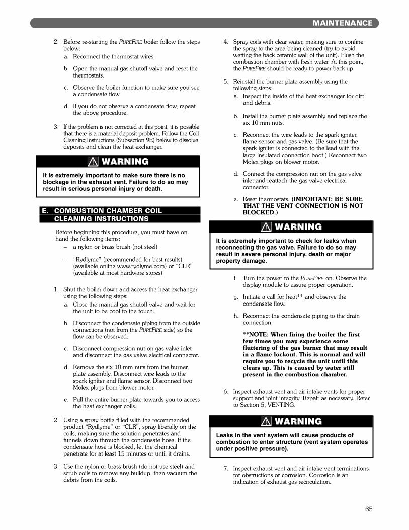
65
MAINTENANCE
2. Before re-starting the PUREFIRE boiler follow the stepsbelow:a. Reconnect the thermostat wires.
b. Open the manual gas shutoff valve and reset thethermostats.
c. Observe the boiler function to make sure you seea condensate flow.
d. If you do not observe a condensate flow, repeatthe above procedure.
3. If the problem is not corrected at this point, it is possiblethat there is a material deposit problem. Follow the CoilCleaning Instructions (Subsection 9E) below to dissolvedeposits and clean the heat exchanger.
E. COMBUSTION CHAMBER COILCLEANING INSTRUCTIONS
Before beginning this procedure, you must have onhand the following items:
– a nylon or brass brush (not steel)
– “Rydlyme” (recommended for best results)(available online www.rydlyme.com) or “CLR”(available at most hardware stores)
1. Shut the boiler down and access the heat exchangerusing the following steps:a. Close the manual gas shutoff valve and wait for
the unit to be cool to the touch.
b. Disconnect the condensate piping from the outsideconnections (not from the PUREFIRE side) so theflow can be observed.
c. Disconnect compression nut on gas valve inletand disconnect the gas valve electrical connector.
d. Remove the six 10 mm nuts from the burnerplate assembly. Disconnect wire leads to thespark igniter and flame sensor. Disconnect twoMolex plugs from blower motor.
e. Pull the entire burner plate towards you to accessthe heat exchanger coils.
2. Using a spray bottle filled with the recommendedproduct “Rydlyme” or “CLR”, spray liberally on thecoils, making sure the solution penetrates andfunnels down through the condensate hose. If thecondensate hose is blocked, let the chemicalpenetrate for at least 15 minutes or until it drains.
3. Use the nylon or brass brush (do not use steel) andscrub coils to remove any buildup, then vacuum thedebris from the coils.
4. Spray coils with clear water, making sure to confinethe spray to the area being cleaned (try to avoidwetting the back ceramic wall of the unit). Flush thecombustion chamber with fresh water. At this point,the PUREFIRE should be ready to power back up.
5. Reinstall the burner plate assembly using thefollowing steps:a. Inspect the inside of the heat exchanger for dirt
and debris.
b. Install the burner plate assembly and replace thesix 10 mm nuts.
c. Reconnect the wire leads to the spark igniter,flame sensor and gas valve. (Be sure that thespark igniter is connected to the lead with thelarge insulated connection boot.) Reconnect twoMolex plugs on blower motor.
d. Connect the compression nut on the gas valveinlet and reattach the gas valve electricalconnector.
e. Reset thermostats. (IMPORTANT: BE SURETHAT THE VENT CONNECTION IS NOTBLOCKED.)
f. Turn the power to the PUREFIRE on. Observe thedisplay module to assure proper operation.
g. Initiate a call for heat** and observe thecondensate flow.
h. Reconnect the condensate piping to the drainconnection.
**NOTE: When firing the boiler the firstfew times you may experience somefluttering of the gas burner that may resultin a flame lockout. This is normal and willrequire you to recycle the unit until thisclears up. This is caused by water stillpresent in the combustion chamber.
6. Inspect exhaust vent and air intake vents for propersupport and joint integrity. Repair as necessary. Referto Section 5, VENTING.
7. Inspect exhaust vent and air intake vent terminationsfor obstructions or corrosion. Corrosion is anindication of exhaust gas recirculation.
It is extremely important to make sure there is noblockage in the exhaust vent. Failure to do so mayresult in serious personal injury or death.
WARNING
It is extremely important to check for leaks whenreconnecting the gas valve. Failure to do so mayresult in severe personal injury, death or majorproperty damage.
WARNING
Leaks in the vent system will cause products ofcombustion to enter structure (vent system operatesunder positive pressure).
WARNING
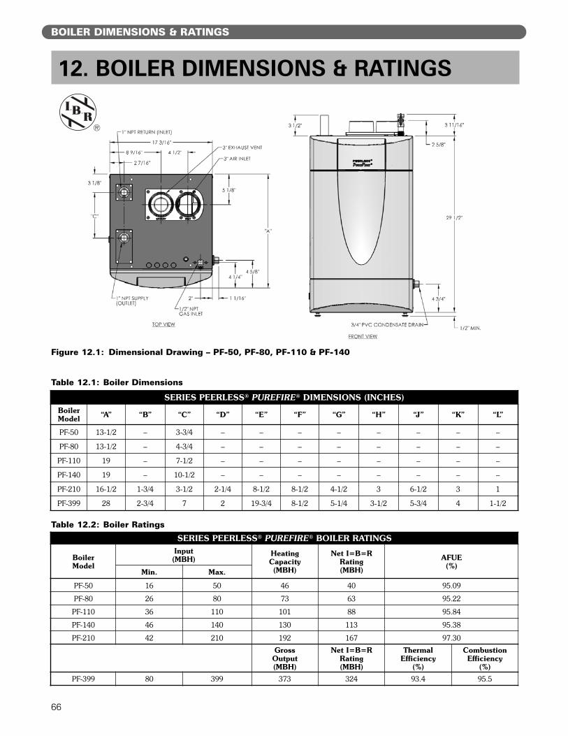
66
BOILER DIMENSIONS & RATINGS
12. BOILER DIMENSIONS & RATINGS
Table 12.1: Boiler Dimensions
SERIES PEERLESS® PUREFIRE® DIMENSIONS (INCHES)BoilerModel “A” “B” “C” “D” “E” “F” “G” “H” “J” “K” “L”
PF-50 13-1/2 – 3-3/4 – – – – – – – –
PF-80 13-1/2 – 4-3/4 – – – – – – – –
PF-110 19 – 7-1/2 – – – – – – – –
PF-140 19 – 10-1/2 – – – – – – – –
PF-210 16-1/2 1-3/4 3-1/2 2-1/4 8-1/2 8-1/2 4-1/2 3 6-1/2 3 1
PF-399 28 2-3/4 7 2 19-3/4 8-1/2 5-1/4 3-1/2 5-3/4 4 1-1/2
Figure 12.1: Dimensional Drawing – PF-50, PF-80, PF-110 & PF-140
Table 12.2: Boiler Ratings
SERIES PEERLESS® PUREFIRE® BOILER RATINGS
BoilerModel
Input(MBH)
HeatingCapacity(MBH)
Net I=B=RRating(MBH)
AFUE(%)
Min. Max.
PF-50 16 50 46 40 95.09
PF-80 26 80 73 63 95.22
PF-110 36 110 101 88 95.84
PF-140 46 140 130 113 95.38
PF-210 42 210 192 167 97.30
GrossOutput(MBH)
Net I=B=RRating(MBH)
ThermalEfficiency
(%)
CombustionEfficiency
(%)
PF-399 80 399 373 324 93.4 95.5
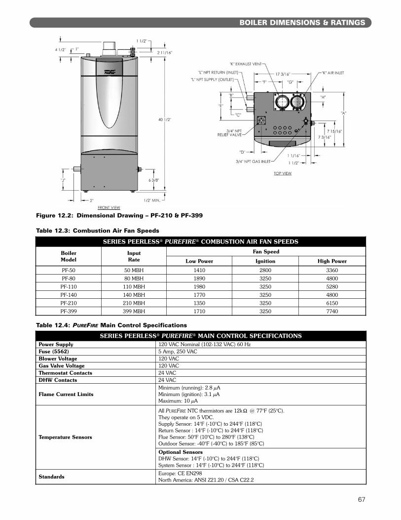
67
BOILER DIMENSIONS & RATINGS
Table 12.3: Combustion Air Fan Speeds
SERIES PEERLESS® PUREFIRE® COMBUSTION AIR FAN SPEEDS
BoilerModel
InputRate
Fan Speed
Low Power Ignition High Power
PF-50 50 MBH 1410 2800 3360PF-80 80 MBH 1890 3250 4800
PF-110 110 MBH 1980 3250 5280PF-140 140 MBH 1770 3250 4800PF-210 210 MBH 1350 3250 6150PF-399 399 MBH 1710 3250 7740
Figure 12.2: Dimensional Drawing – PF-210 & PF-399
Table 12.4: PUREFIRE Main Control Specifications
SERIES PEERLESS® PUREFIRE® MAIN CONTROL SPECIFICATIONSPower Supply 120 VAC Nominal (102-132 VAC) 60 HzFuse (5562) 5 Amp, 250 VACBlower Voltage 120 VACGas Valve Voltage 120 VACThermostat Contacts 24 VACDHW Contacts 24 VAC
Flame Current LimitsMinimum (running): 2.8 µAMinimum (ignition): 3.1 µAMaximum: 10 µA
Temperature Sensors
All PUREFIRE NTC thermistors are 12k" @ 77°F (25°C).They operate on 5 VDC.Supply Sensor: 14°F (-10°C) to 244°F (118°C)Return Sensor : 14°F (-10°C) to 244°F (118°C)Flue Sensor: 50°F (10°C) to 280°F (138°C)Outdoor Sensor: -40°F (-40°C) to 185°F (85°C)
Optional SensorsDHW Sensor: 14°F (-10°C) to 244°F (118°C)System Sensor : 14°F (-10°C) to 244°F (118°C)
Standards Europe: CE EN298North America: ANSI Z21.20 / CSA C22.2
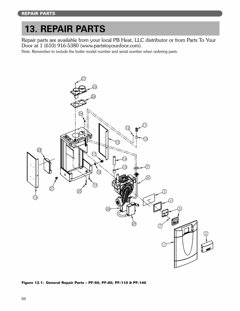
68
REPAIR PARTS
Repair parts are available from your local PB Heat, LLC distributor or from Parts To YourDoor at 1 (610) 916-5380 (www.partstoyourdoor.com).Note: Remember to include the boiler model number and serial number when ordering parts.
13. REPAIR PARTS
Figure 13.1: General Repair Parts – PF-50, PF-80, PF-110 & PF-140
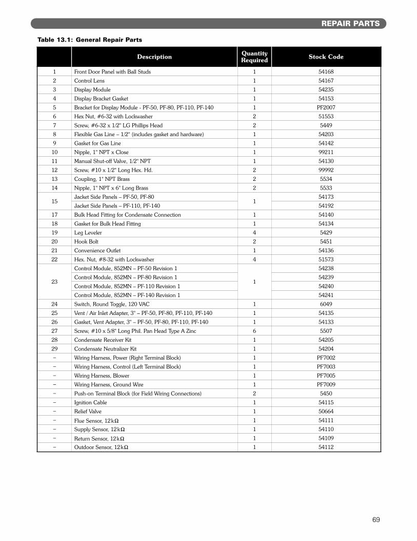
69
REPAIR PARTS
Description QuantityRequired Stock Code
1 Front Door Panel with Ball Studs 1 54168
2 Control Lens 1 54167
3 Display Module 1 54235
4 Display Bracket Gasket 1 54153
5 Bracket for Display Module - PF-50, PF-80, PF-110, PF-140 1 PF2007
6 Hex Nut, #6-32 with Lockwasher 2 51553
7 Screw, #6-32 x 1/2" LG Phillips Head 2 5449
8 Flexible Gas Line – 1/2" (includes gasket and hardware) 1 54203
9 Gasket for Gas Line 1 54142
10 Nipple, 1" NPT x Close 1 99211
11 Manual Shut-off Valve, 1/2" NPT 1 54130
12 Screw, #10 x 1/2" Long Hex. Hd. 2 99992
13 Coupling, 1" NPT Brass 2 5534
14 Nipple, 1" NPT x 6" Long Brass 2 5533
15Jacket Side Panels – PF-50, PF-80
154173
Jacket Side Panels – PF-110, PF-140 54192
17 Bulk Head Fitting for Condensate Connection 1 54140
18 Gasket for Bulk Head Fitting 1 54134
19 Leg Leveler 4 5429
20 Hook Bolt 2 5451
21 Convenience Outlet 1 54136
22 Hex. Nut, #8-32 with Lockwasher 4 51573
23
Control Module, 852MN – PF-50 Revision 1
1
54238
Control Module, 852MN – PF-80 Revision 1 54239
Control Module, 852MN – PF-110 Revision 1 54240
Control Module, 852MN – PF-140 Revision 1 54241
24 Switch, Round Toggle, 120 VAC 1 6049
25 Vent / Air Inlet Adapter, 3" – PF-50, PF-80, PF-110, PF-140 1 54135
26 Gasket, Vent Adapter, 3" – PF-50, PF-80, PF-110, PF-140 1 54133
27 Screw, #10 x 5/8" Long Phil. Pan Head Type A Zinc 6 5507
28 Condensate Receiver Kit 1 54205
29 Condensate Neutralizer Kit 1 54204– Wiring Harness, Power (Right Terminal Block) 1 PF7002– Wiring Harness, Control (Left Terminal Block) 1 PF7003– Wiring Harness, Blower 1 PF7005– Wiring Harness, Ground Wire 1 PF7009– Push-on Terminal Block (for Field Wiring Connections) 2 5450– Ignition Cable 1 54115– Relief Valve 1 50664– Flue Sensor, 12k" 1 54111– Supply Sensor, 12k" 1 54110– Return Sensor, 12k" 1 54109– Outdoor Sensor, 12k" 1 54112
Table 13.1: General Repair Parts
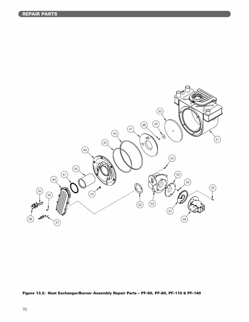
70
REPAIR PARTS
Figure 13.2: Heat Exchanger/Burner Assembly Repair Parts – PF-50, PF-80, PF-110 & PF-140
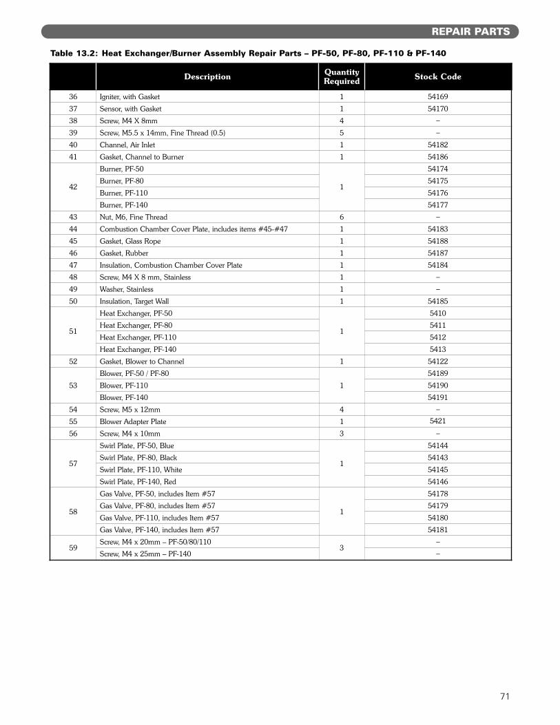
71
REPAIR PARTS
Description QuantityRequired Stock Code
36 Igniter, with Gasket 1 54169
37 Sensor, with Gasket 1 54170
38 Screw, M4 X 8mm 4 –
39 Screw, M5.5 x 14mm, Fine Thread (0.5) 5 –
40 Channel, Air Inlet 1 54182
41 Gasket, Channel to Burner 1 54186
42
Burner, PF-50
1
54174
Burner, PF-80 54175
Burner, PF-110 54176
Burner, PF-140 54177
43 Nut, M6, Fine Thread 6 –
44 Combustion Chamber Cover Plate, includes items #45-#47 1 54183
45 Gasket, Glass Rope 1 54188
46 Gasket, Rubber 1 54187
47 Insulation, Combustion Chamber Cover Plate 1 54184
48 Screw, M4 X 8 mm, Stainless 1 –
49 Washer, Stainless 1 –
50 Insulation, Target Wall 1 54185
51
Heat Exchanger, PF-50
1
5410
Heat Exchanger, PF-80 5411
Heat Exchanger, PF-110 5412
Heat Exchanger, PF-140 5413
52 Gasket, Blower to Channel 1 54122
53
Blower, PF-50 / PF-80
1
54189
Blower, PF-110 54190
Blower, PF-140 54191
54 Screw, M5 x 12mm 4 –
55 Blower Adapter Plate 1 5421
56 Screw, M4 x 10mm 3 –
57
Swirl Plate, PF-50, Blue
1
54144
Swirl Plate, PF-80, Black 54143
Swirl Plate, PF-110, White 54145
Swirl Plate, PF-140, Red 54146
58
Gas Valve, PF-50, includes Item #57
1
54178
Gas Valve, PF-80, includes Item #57 54179
Gas Valve, PF-110, includes Item #57 54180
Gas Valve, PF-140, includes Item #57 54181
59Screw, M4 x 20mm – PF-50/80/110
3–
Screw, M4 x 25mm – PF-140 –
Table 13.2: Heat Exchanger/Burner Assembly Repair Parts – PF-50, PF-80, PF-110 & PF-140
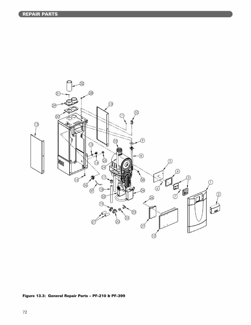
72
REPAIR PARTS
Figure 13.3: General Repair Parts – PF-210 & PF-399
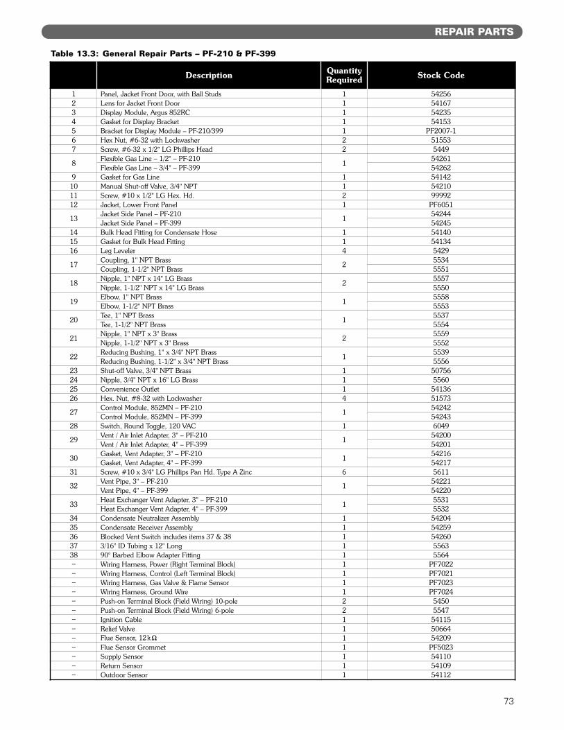
73
REPAIR PARTS
Table 13.3: General Repair Parts – PF-210 & PF-399
Description QuantityRequired Stock Code
1 Panel, Jacket Front Door, with Ball Studs 1 542562 Lens for Jacket Front Door 1 541673 Display Module, Argus 852RC 1 542354 Gasket for Display Bracket 1 541535 Bracket for Display Module – PF-210/399 1 PF2007-16 Hex Nut, #6-32 with Lockwasher 2 515537 Screw, #6-32 x 1/2" LG Phillips Head 2 5449
8Flexible Gas Line – 1/2" – PF-210
154261
Flexible Gas Line – 3/4" – PF-399 542629 Gasket for Gas Line 1 54142
10 Manual Shut-off Valve, 3/4" NPT 1 5421011 Screw, #10 x 1/2" LG Hex. Hd. 2 9999212 Jacket, Lower Front Panel 1 PF6051
13Jacket Side Panel – PF-210
154244
Jacket Side Panel – PF-399 5424514 Bulk Head Fitting for Condensate Hose 1 5414015 Gasket for Bulk Head Fitting 1 5413416 Leg Leveler 4 5429
17Coupling, 1" NPT Brass
25534
Coupling, 1-1/2" NPT Brass 5551
18Nipple, 1" NPT x 14" LG Brass
25557
Nipple, 1-1/2" NPT x 14" LG Brass 5550
19Elbow, 1" NPT Brass
15558
Elbow, 1-1/2" NPT Brass 5553
20Tee, 1" NPT Brass
15537
Tee, 1-1/2" NPT Brass 5554
21Nipple, 1" NPT x 3" Brass
25559
Nipple, 1-1/2" NPT x 3" Brass 5552
22Reducing Bushing, 1" x 3/4" NPT Brass
15539
Reducing Bushing, 1-1/2" x 3/4" NPT Brass 555623 Shut-off Valve, 3/4" NPT Brass 1 5075624 Nipple, 3/4" NPT x 16" LG Brass 1 556025 Convenience Outlet 1 5413626 Hex. Nut, #8-32 with Lockwasher 4 51573
27Control Module, 852MN – PF-210
154242
Control Module, 852MN – PF-399 5424328 Switch, Round Toggle, 120 VAC 1 6049
29Vent / Air Inlet Adapter, 3" – PF-210
154200
Vent / Air Inlet Adapter, 4" – PF-399 54201
30Gasket, Vent Adapter, 3" – PF-210
154216
Gasket, Vent Adapter, 4" – PF-399 5421731 Screw, #10 x 3/4" LG Phillips Pan Hd. Type A Zinc 6 5611
32Vent Pipe, 3" – PF-210
154221
Vent Pipe, 4" – PF-399 54220
33Heat Exchanger Vent Adapter, 3" – PF-210
15531
Heat Exchanger Vent Adapter, 4" – PF-399 553234 Condensate Neutralizer Assembly 1 5420435 Condensate Receiver Assembly 1 5425936 Blocked Vent Switch includes items 37 & 38 1 5426037 3/16" ID Tubing x 12" Long 1 556338 90° Barbed Elbow Adapter Fitting 1 5564– Wiring Harness, Power (Right Terminal Block) 1 PF7022– Wiring Harness, Control (Left Terminal Block) 1 PF7021– Wiring Harness, Gas Valve & Flame Sensor 1 PF7023– Wiring Harness, Ground Wire 1 PF7024– Push-on Terminal Block (Field Wiring) 10-pole 2 5450– Push-on Terminal Block (Field Wiring) 6-pole 2 5547– Ignition Cable 1 54115– Relief Valve 1 50664– Flue Sensor, 12k" 1 54209– Flue Sensor Grommet 1 PF5023– Supply Sensor 1 54110– Return Sensor 1 54109– Outdoor Sensor 1 54112
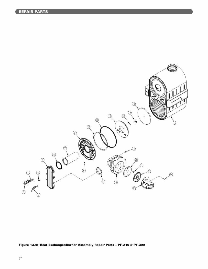
74
Figure 13.4: Heat Exchanger/Burner Assembly Repair Parts – PF-210 & PF-399
REPAIR PARTS
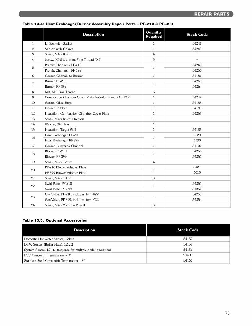
75
REPAIR PARTS
Table 13.4: Heat Exchanger/Burner Assembly Repair Parts – PF-210 & PF-399
Table 13.5: Optional Accessories
Description QuantityRequired Stock Code
1 Ignitor, with Gasket 1 54246
2 Sensor, with Gasket 1 54247
3 Screw, M4 x 8mm 4 –
4 Screw, M5.5 x 14mm, Fine Thread (0.5) 5 –
5Premix Channel – PF-210
154249
Premix Channel – PF-399 54250
6 Gasket, Channel to Burner 1 54186
7Burner, PF-210
154263
Burner, PF-399 54264
8 Nut, M6, Fine Thread 6 –
9 Combustion Chamber Cover Plate, includes items #10-#12 1 54248
10 Gasket, Glass Rope 1 54188
11 Gasket, Rubber 1 54187
12 Insulation, Combustion Chamber Cover Plate 1 54255
13 Screw, M4 x 8mm, Stainless 1 –
14 Washer, Stainless 1 –
15 Insulation, Target Wall 1 54185
16Heat Exchanger, PF-210
15529
Heat Exchanger, PF-399 5530
17 Gasket, Blower to Channel 1 54122
18Blower, PF-210
154258
Blower, PF-399 54257
19 Screw, M5 x 12mm 4 –
20PF-210 Blower Adapter Plate
15421
PF-399 Blower Adapter Plate 5610
21 Screw, M4 x 10mm 3 –
22Swirl Plate, PF-210
154251
Swirl Plate, PF-399 54252
23Gas Valve, PF-210, includes item #22
154253
Gas Valve, PF-399, includes item #22 54254
24 Screw, M4 x 25mm – PF-210 3 –
Description Stock Code
Domestic Hot Water Sensor, 12 k" 54157
DHW Sensor (Boiler Mate), 12 k" 54158
System Sensor, 12 k" (required for multiple boiler operation) 54156
PVC Concentric Termination – 3" 91403
Stainless Steel Concentric Termination – 3" 54161
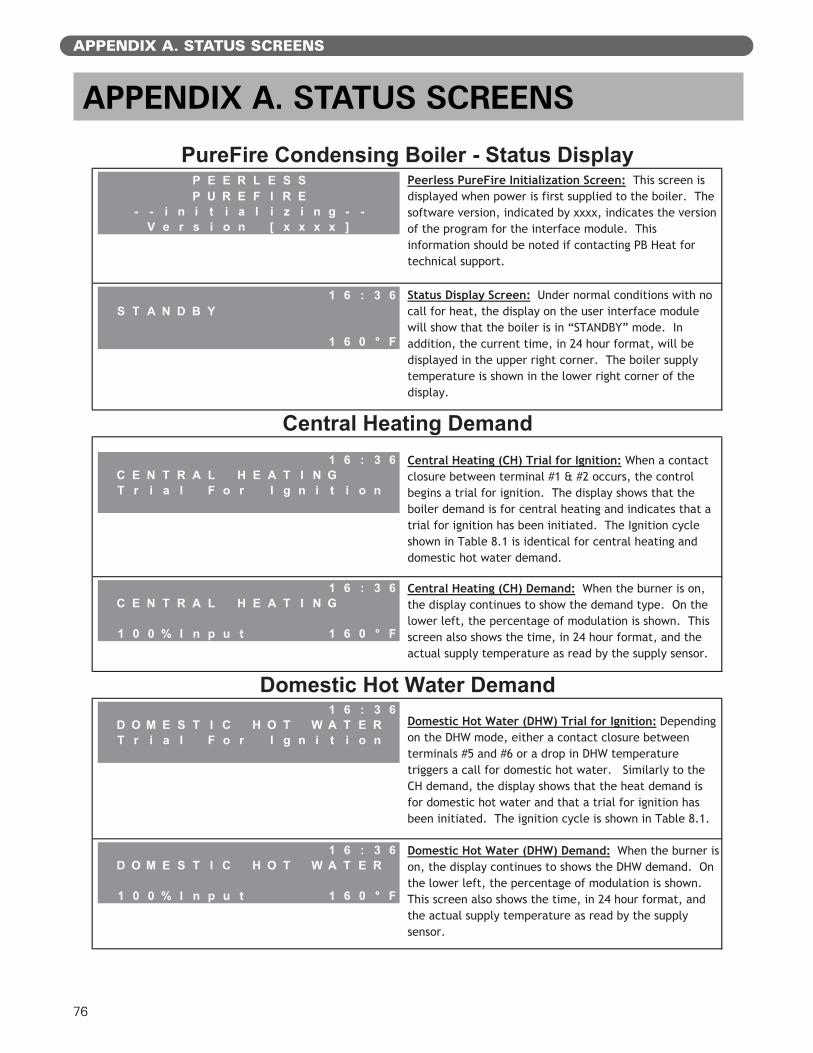
76
APPENDIX A. STATUS SCREENS
APPENDIX A. STATUS SCREENS
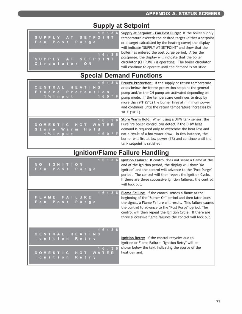
77
APPENDIX A. STATUS SCREENS
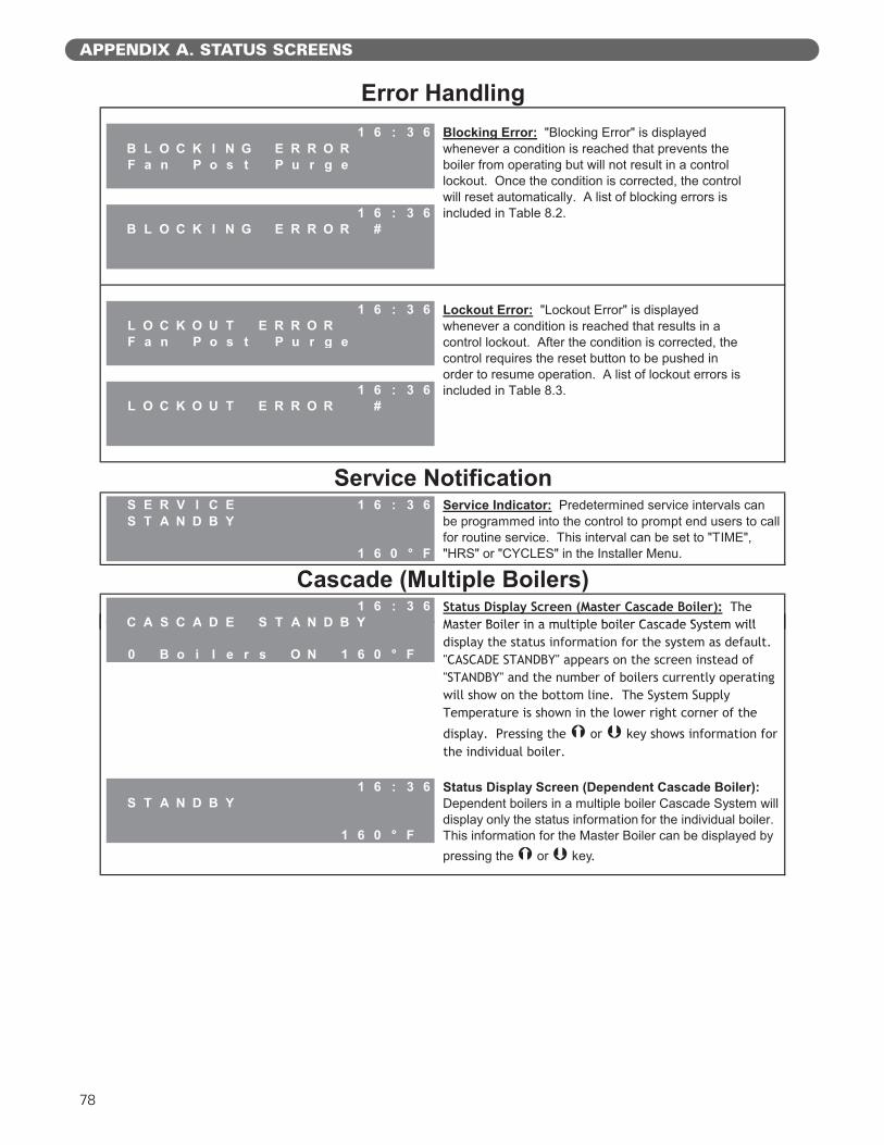
78
APPENDIX A. STATUS SCREENS
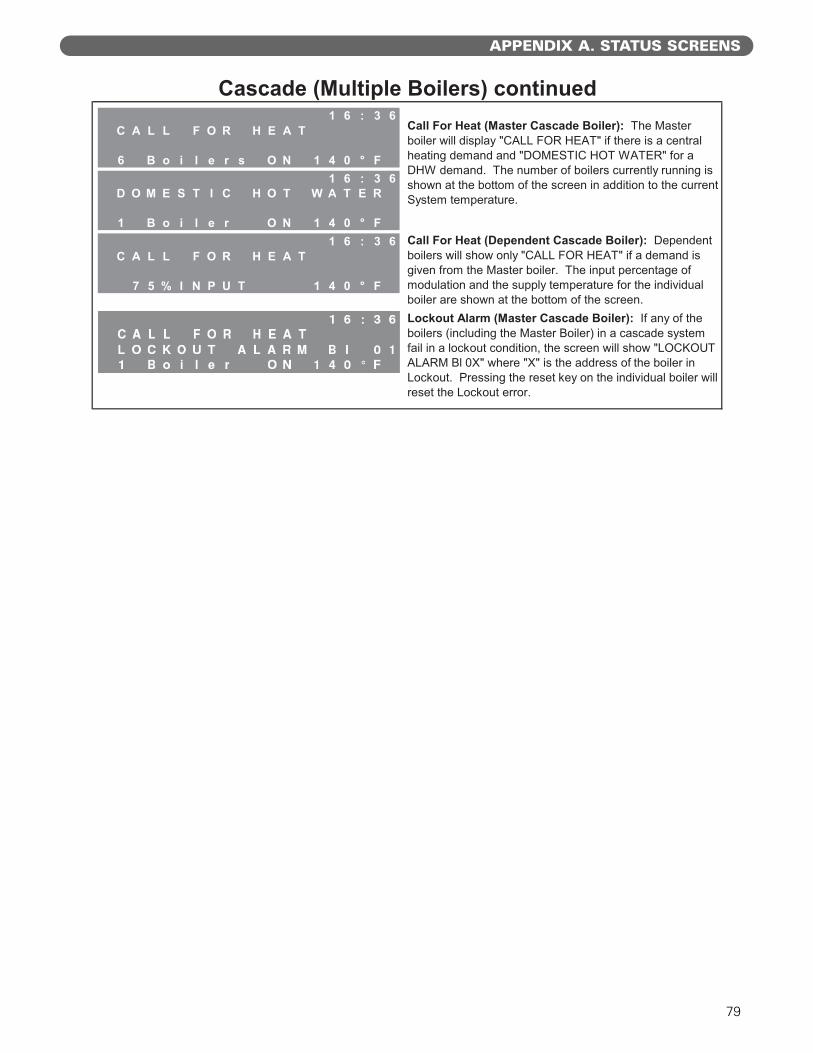
79
APPENDIX A. STATUS SCREENS

80
APPENDIX B. USER MENU
APPENDIX B. USER MENU
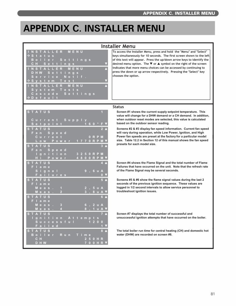
81
APPENDIX C. INSTALLER MENU
APPENDIX C. INSTALLER MENU
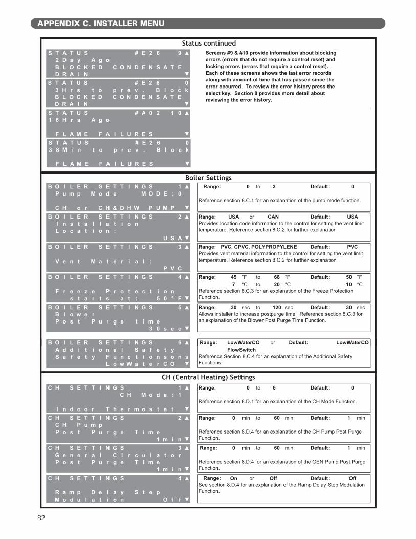
82
APPENDIX C. INSTALLER MENU
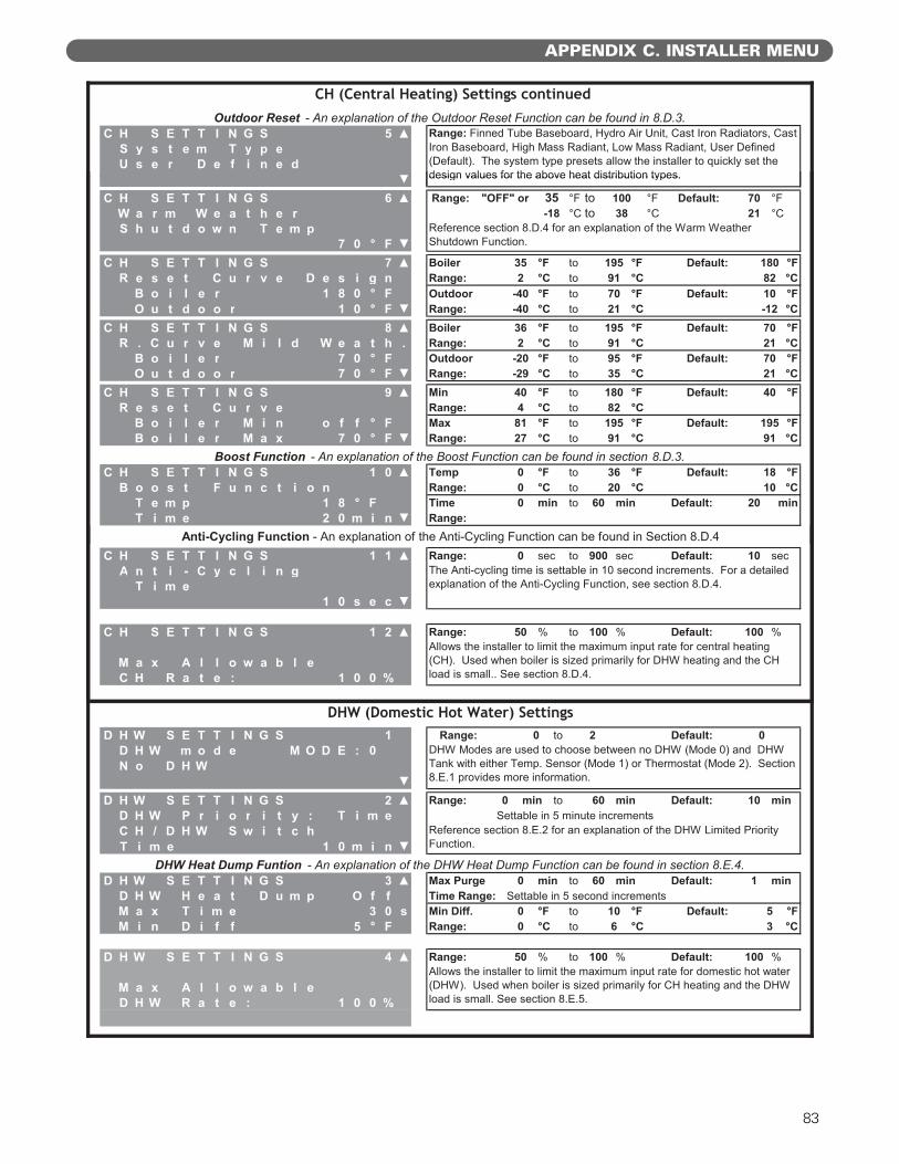
83
APPENDIX C. INSTALLER MENU
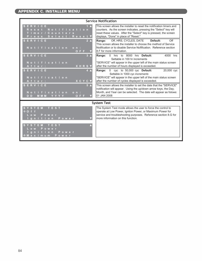
84
APPENDIX C. INSTALLER MENU
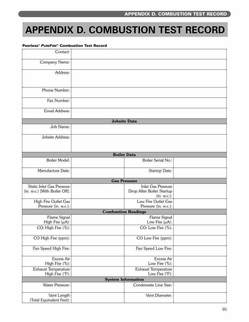
85
APPENDIX D. COMBUSTION TEST RECORD
APPENDIX D. COMBUSTION TEST RECORD
Contact:
Company Name:
Address:
Phone Number:
Fax Number:
Email Address:
Jobsite DataJob Name:
Jobsite Address:
Boiler DataBoiler Model: Boiler Serial No.:
Manufacture Date: Startup Date:
Gas PressureStatic Inlet Gas Pressure
(in. w.c.) [With Boiler Off]:Inlet Gas Pressure
Drop After Boiler Startup (in. w.c.):
High Fire Outlet GasPressure (in. w.c.):
Low Fire Outlet GasPressure (in. w.c.):
Combustion ReadingsFlame Signal
High Fire (µA):Flame Signal
Low Fire (µA):CO" High Fire (%): CO" Low Fire (%):
CO High Fire (ppm): CO Low Fire (ppm):
Fan Speed High Fire: Fan Speed Low Fire:
Excess Air High Fire (%):
Excess Air Low Fire (%):
Exhaust Temperature High Fire (°F):
Exhaust Temperature Low Fire (°F):
System InformationWater Pressure: Condensate Line Size:
Vent Length(Total Equivalent Feet):
Vent Diameter:
Peerless® PUREFIRE® Combustion Test Record

®
BoilersGas
Installation,Operation &MaintenanceManualTO THE INSTALLER:
This manual is the property of the owner and mustbe affixed near the boiler for future reference.
TO THE OWNER:This boiler should be inspected annually by aQualified Service Agency.
PF8080 R5 (5/10-3M)Printed in U.S.A.©2010
PB HEAT, LLC131 S. CHURCH STREET • BALLY, PA 19503
CONTROLS
ASME
PF-50 PF-80 PF-110 PF-140 PF-210 PF-399
PUREFIRE ® REV2